EP2186576A1 - Method and device for sorting products - Google Patents
Method and device for sorting products Download PDFInfo
- Publication number
- EP2186576A1 EP2186576A1 EP08447046A EP08447046A EP2186576A1 EP 2186576 A1 EP2186576 A1 EP 2186576A1 EP 08447046 A EP08447046 A EP 08447046A EP 08447046 A EP08447046 A EP 08447046A EP 2186576 A1 EP2186576 A1 EP 2186576A1
- Authority
- EP
- European Patent Office
- Prior art keywords
- light
- product
- light beam
- products
- stream
- Prior art date
- Legal status (The legal status is an assumption and is not a legal conclusion. Google has not performed a legal analysis and makes no representation as to the accuracy of the status listed.)
- Granted
Links
- 238000000034 method Methods 0.000 title claims abstract description 25
- 238000001514 detection method Methods 0.000 claims abstract description 60
- 238000001228 spectrum Methods 0.000 claims description 12
- 239000003365 glass fiber Substances 0.000 claims description 10
- 230000007423 decrease Effects 0.000 claims description 6
- 230000035945 sensitivity Effects 0.000 claims description 2
- 239000000470 constituent Substances 0.000 description 15
- 238000009792 diffusion process Methods 0.000 description 3
- 241000143060 Americamysis bahia Species 0.000 description 1
- 240000004713 Pisum sativum Species 0.000 description 1
- 235000010582 Pisum sativum Nutrition 0.000 description 1
- 240000006365 Vitis vinifera Species 0.000 description 1
- 235000014787 Vitis vinifera Nutrition 0.000 description 1
- 238000013459 approach Methods 0.000 description 1
- 230000023077 detection of light stimulus Effects 0.000 description 1
- 239000000463 material Substances 0.000 description 1
Images


Classifications
-
- B—PERFORMING OPERATIONS; TRANSPORTING
- B07—SEPARATING SOLIDS FROM SOLIDS; SORTING
- B07C—POSTAL SORTING; SORTING INDIVIDUAL ARTICLES, OR BULK MATERIAL FIT TO BE SORTED PIECE-MEAL, e.g. BY PICKING
- B07C5/00—Sorting according to a characteristic or feature of the articles or material being sorted, e.g. by control effected by devices which detect or measure such characteristic or feature; Sorting by manually actuated devices, e.g. switches
- B07C5/34—Sorting according to other particular properties
- B07C5/342—Sorting according to other particular properties according to optical properties, e.g. colour
- B07C5/3425—Sorting according to other particular properties according to optical properties, e.g. colour of granular material, e.g. ore particles, grain
- B07C5/3427—Sorting according to other particular properties according to optical properties, e.g. colour of granular material, e.g. ore particles, grain by changing or intensifying the optical properties prior to scanning, e.g. by inducing fluorescence under UV or x-radiation, subjecting the material to a chemical reaction
Definitions
- the invention concerns a method for detecting and possibly removing inferior products and/or strange constituents from a product flow, whereby at least one light beam is directed to these products which move according to a certain direction through a detection zone, such that this light beam is at least partly scattered and/or reflected by said products, whereby the scattered light at least partly enters a detector, and whereby constituents or products which scatter the light can be distinguished from suitable products in a way which differs from that of the latter.
- said products are moved over a reference element in said detection zone which scatters said light beam in a way similar to that of a good product.
- This is described in American patent US 4,723,659 .
- the aim here is to detect only strange constituents or inferior products by means of a sorting device and to possibly remove them. Suitable products are not detected.
- edge effects are produced with inferior products, strange constituents as well as suitable products in the signal which is generated when said light beam moves over one or several products, since said light beam moves from the reference element to the products and vice versa. These edge effects may result in an incorrect identification by the sorting device.
- the invention aims to provide a method which makes it possible to identify products in a very accurate manner, whereby edge effects no longer have any influence whatsoever.
- a stream of light is generated in the detection zone between a reference element and said scan means, whereby the intensity of this stream of light is observed in a direction which substantially corresponds to the direction of said light beam and, when this intensity exceeds a preset value, in particular when it is lower than this preset value, a product which is hit by the light beam will be qualified as a suitable product or as an inferior or a strange product as a function of the detection signal of at least one detector.
- said products are illuminated by means of a light source, forming a stream of light with a frequency spectrum which is at least partly different from the spectrum of said light beam.
- said products move through the detection zone, they will at least partly disturb said stream of light. This disturbance is detected, and when such a disturbance occurs with a product in a position near or on the path of the above-mentioned light beam, this product will be identified as a strange constituent, an inferior product or a suitable product by means of said light beam.
- said products are illuminated by said stream of light on the side which is mainly opposite to the side where said light beam impinges upon the products, and said stream of light is detected on the last-mentioned side of the product in such a direction that, when a product is situated in a position near or on the path of said light beam, the disturbance of the stream of light by this product can be observed in the direction of said light beam, whereby subsequently, when such a disturbance occurs, the product will be identified as a strange constituent, an inferior product or a suitable product.
- said product will be identified by means of said light beam when it impinges entirely upon the product and, consequently, the light scattered by this product can be detected substantially without any influences of edge effects.
- the signal when said light beam moves over a product, the signal, generated by said detector as a result of light of the light beam entering it as scattered by the product, will only be used to identify the product when the disturbance of the stream of light coming from said light source has reached a predetermined detection level, whereby said signal is no longer used to identify the product when said level is exceeded again as said disturbance decreases.
- said light beam impinges upon said reference element and forms said stream of light, whereby this stream of light is guided at least partly to a detector via the reference element which detects the intensity of the stream of light and converts it in an intensity signal, whereby the product is qualified when this intensity signal exceeds a preset value.
- the invention also concerns a sorting device to apply the method according to the invention, in particular for separating inferior products and/or strange constituents from products which move in a certain direction through a detection zone, with a detection device which is provided with at least two detectors and with means to generate at least one light beam directed to said products, moving crosswise to the direction of movement thereof, such that the light of this light beam is scattered and/or reflected by said products, whereby the light which is scattered by said products at least partly enters a first detector.
- this sorting device is provided with a light source which generates light which can be distinguished from that of said light beam, in particular light which has a frequency spectrum which is at least partly different from that of the light of said light beam and which is directed such that it becomes possible to illuminate said products, and whereby a second detector is provided which measures a disturbance of the stream of light coming from said light source by at least one of the products.
- the detector which measures the disturbance of said stream of light is mounted such that this disturbance is measured according to the direction of said light beam.
- said light source is longitudinal and it extends at least partly in said detection zone, such that said light beam moves over the light source.
- the sorting device comprises means for generating a stream of light in the detection zone between a reference element and scan means, whereby at least one second detector is provided which makes it possible to detect the intensity of said stream of light in a direction which corresponds substantially to the direction of said light beam and to generate a corresponding intensity signal, whereby this sorting device comprises means to compare the intensity signal to a preset value, whereby means are further provided to qualify a product hit by the light beam, when said intensity signal exceeds the preset value, as a suitable product or as an inferior or strange product as a function of the detection signal of said first detector.
- the reference instrument of this variant of the sorting device preferably comprises a light-conducting instrument which is connected to and works in conjunction with said second detector.
- Figure 1 is a schematic view in perspective of a sorting device according to the state of the art.
- Figure 2 schematically represents a detection device according to the state of the art.
- Figure 3 is a schematic view of a reference element with a product, represented according to the direction of movement of the product, with an accompanying graph which represents the signal coming from light of said light beam, generated by a detector, as the light beam moves over the product.
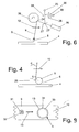
- Figure 4 is a schematic view of a reference element, represented according to the direction of movement of a product to be detected.
- Figure 5 is a schematic view of two products situated next to one another and a reference element, represented according to the direction of movement of these products with an accompanying graph which represents the signal coming from light of said light beam, generated by a detector, as this light beam moves over the products.
- Figure 6 schematically represents a detection device according to the invention.
- Figure 7 is a schematic view of a product with a light source according to the invention, represented according to the direction of movement of the product, with an accompanying graph which represents the signal coming from light of said light sources, generated by a detector.
- Figure 8 is a schematic view of two products situated next to one another and a light source according to the invention, represented according to the direction of movement of these products with an accompanying graph which represents the signal coming from light of said light beam, generated by a detector.
- Figure 9 is a schematic top view of a part of the light source according to the invention with a product to be identified.
- Figure 1 shows a traditional sorting device which is provided with a conveyor belt 1, a compressed air device 2 and a detection device 3 working in conjunction with a reference element 4.
- the detection device 3 is schematically represented in figure 2 .
- products 5 consisting of loose parts such as peas, raisins, shrimps, nuts, fries or granular products are moved over said reference element 4 through a detection zone 6.
- the far end of the conveyor belt 1 extends up to the reference element 4, such that products 5 which are moved by the conveyor belt 1 according to arrow 1' in the direction of the detection zone 6 and the reference element 4, when leaving the conveyor belt 1, have a sufficiently large speed to successively move through the detection zone 6 over the reference element 4 and under the compressed air device 2.
- a light source 26 of said detection device 3 generates a light beam 9, in particular a laser beam, directed to the reference element 4 and moving at a relatively high frequency over the latter through the detection zone 6.
- the light beam 9 enters a rotating, regular, octagonal prism 25 provided with mirror surfaces 24 and it is reflected to the reference element 4, as is schematically represented in figure 2 .
- Such a prism 25 is also called a polygon mirror and it is part of what are called the scan means.
- the light beam 9 moves according to arrow 10 over the reference element 4. This light beam 9 thus enters the products 5 moving through said detection zone 6 and it will be scattered and/or reflected by the products 5.
- scattered light the light which is reflected in a diffuse manner at the surface of a product 5 on the one hand, and the light which is emitted by the product 5 on the other hand as said light beam 9 at least partly penetrates the latter and is scattered therein, thus illuminating at least a part of the product 5.
- the scattered light is normally not polarized, as opposed to the light of the light beam 9.
- Every product 5 is identified as a strange constituent, an inferior product or a suitable product 5 according to techniques known as such.
- Light that is scattered by the product 5 is hereby discerned by a detector 23 and, on the basis of the signal generated by the detector 23, the above-mentioned identification takes place.
- Said detector 23 discerns the scattered light which enters a mirror 27 according to the path of the light beam 9 via the mirror surface 24.
- the latter mirror 27 reflects the scattered light to a polarisation filter 28 and the detector 23.
- the polarisation filter 28 By means of the polarisation filter 28, light that is not scattered but that is for example directly reflected by a product 5 is prevented from entering the detector 23.
- the mirror 27 is provided with a central opening 27' through which the light beam 9, coming from light source 26, enters the mirror surface 24.
- a reference element 4 in the shape of a longitudinal tube according to the present state of the art preferably having substantially similar diffusion qualities as a suitable product 5 for the used light beam 9. This makes sure that, when there is no product 5 under said light beam, there will nevertheless be a diffusion of the light beam which approaches the diffusion of a suitable product 5, such that said compressed air device 2 is not needlessly activated.
- Figure 3 shows a light beam 9 which moves over said reference element 4 according to arrow 10.
- a signal 11 will be generated by said detector 23 which is provided on the detection device 3 and discerns the light which is scattered by this product 5.
- the level 12 of this signal 11 has a value that is in relation to the amount of scattered light which is discerned by said detector 23 and which comes from the reference element 4.
- the light beam 9 moves according to arrow 10 and reaches a product 5, it will first be only partly interrupted by the product 5. This has for a result that a part of the light beam 9 is scattered by the product 5 on the one hand, and that the other part of the light beam 9 enters the reference element 4 and is scattered there on the other hand.
- the light which is scattered at this reference element 4 is largely screened from said detector 23 by the product 5. This is also the case when the light closely passes the product 5.
- the detector 23 discerns the scattered light in a direction which substantially coincides with the direction of said light beam 9 on the side of the products 5 opposite to said reference element 4. This results in an edge effect, in particular what is called a shadow effect.
- suitable products 5 may possibly be identified as strange constituents or inferior products.
- a strange constituent or inferior product may be identified as a suitable product 5. Consequently, such an edge effect has an influence on the quality of the sorted products 5 and it should be avoided.
- the signal 11 generated by the detector 23 reaches a level 15 for a suitable product 5.
- the height of this level 15 determines whether a product 5 is either or not identified as a strange constituent, an inferior product or a suitable product.
- a second type of edge effect occurs when two products 5 are situated at a short distance from one another, or substantially against one another while moving through said detection zone 6. Such a situation is represented in figure 5 .
- the light beam 9 will substantially not be scattered or not be scattered at all by these products 5, and it will enter the reference element 4 between the latter.
- This reference element 4 scatters the light coming from the light beam 9, but this scattered light cannot be discerned, or only to a very small extent, by said detector 23 as the products 5 are situated between the latter and the light scattered by the reference element 4.
- the signal 11 of this detector 23, due to the shadow effect will evolve to a level 14 which is usually different from the level 15 of the signal 11 for a suitable product 5 or from the level 12 of this signal 11 for the reference element 4. This may lead to a wrong identification of the products 5, whereby for example an inferior product is identified as being suitable.
- the invention aims to prevent said edge effects from having any influence on the identification of the products 5.
- said products are illuminated by a light source 16 forming a stream of light with a frequency spectrum which is at least partly different from that of the light of said light beam 9.
- a light source 16 forming a stream of light with a frequency spectrum which is at least partly different from that of the light of said light beam 9.
- Said stream of light is mainly formed in the detection zone 6, such that products 5 moving through the latter at least partly disturb this stream of light.
- a disturbance is caused by a product 5 situated in the vicinity of said light beam 9 or which is at least partly entered by the latter, the product 5 will be identified by means of said detection device 3. This makes it possible to only identify a product 5 when said beam 9 entirely enters the latter or, in other words, when said edge effects do not occur.
- Figures 6 , 7 and 8 schematically represent the above-mentioned light source 16.
- This light source 16 is longitudinal and extends over substantially the entire length of the detection zone 6, and it thus replaces the above-mentioned reference element 4 in the embodiment according to figure 1 . Consequently, the stream of light generated by the light source 16 partly enters the side 17 of a product 5 directed towards the latter moving crosswise over it. This side 17 is situated opposite to the side 18 of the product 5 which is hit by the light beam 9.
- the detection device of the sorting device according to the invention differs from the detection device of figure 2 in that it comprises among others a light source 16 and an additional detector 30.
- the light scattered by a product 5 and coming from the light source 16 6 is directed via a mirror surface 24 and a mirror 27 to the above-mentioned polarisation filter 28.
- the latter partly reflects the light from the light source 16 to the detector 30.
- this detector 30 will notice a disturbance in the stream of light when a product 5 is situated in a position near or on the path of the light beam 9.
- the direction in which said detector 30 observes the stream of light will vary in the same manner as that of the light beam 9.
- a signal 19 is obtained in this detector 30, as represented in the graph at the bottom of figure 7 , when the light beam 9 moves over a product 5 which is situated in said stream of light.
- the size of the signal 19 is represented as a function of time.
- This signal 19 will have a constant level 20 when the stream of light is not disturbed by a product 5 in the direction according to which it is being detected.
- the perimeter 13 of the product 5 When the perimeter 13 of the product 5 is transgressed, the observed stream of light will be disturbed and the signal 19 will decrease to a level 21 whereby the light source 16 is substantially entirely screened from the detector 30 by the product 5.
- a level 20 When the perimeter 13 is transgressed again by the light beam 9 according to arrow 10, a level 20 will be reached again for the signal 19 whereby the stream of light will not be disturbed.
- a detection level 22 is set which has been selected such that, when the signal 19 decreases, as the level 22 is transgressed, the light beam 9 will enter the product 5 concerned over its entire cross section, or at least partly. Thus, when this detection level 22 of the signal 19 is transgressed again, the part of the light beam 9 entering the product 5 will decrease.
- scattered light coming from the light beam 9 will be only used to identify a product 5 when the disturbance of the stream of light coming from said light source 16 has reached a predetermined detection level 22, and the signal 11 for light that is scattered by a product 5 will be no longer used to identify this product 5 when the detection level 22 is reached again as said disturbance decreases.
- Figure 8 shows a graph which is analogous to the graph in figure 7 . However, the graph in figure 8 represents a signal 19 which is observed when said light beam moves over two products 5 situated very close to one another.
- the device is provided with a lens 35, as shown in figure 6 , and an adjustable diaphragm 36.
- This diaphragm 36 is situated in the focal plane of the lens 35 where the light which is reflected by the polarisation filter 28 enters. In this focal plane is formed an image of a possible disturbance of the stream of light by a product 5.
- the size of the diaphragm 36 the amount of light entering the detector 30 can be adjusted or, in other words, the gradient of the signal 19 in figures 8 and 9 can be determined when this signal 19 is situated between level 20 and level 21.
- said products 5 are mainly illuminated by said light source 16 on the side of the products 5 where the light beam 9 enters.
- a disturbance in the stream of light is detected by observing the light of this stream of light which is scattered or reflected by a product 5.
- This detection is preferably done according to the direction of said light beam 9, i.e. when a product 5 is situated near or in the path of said light beam 9.
- the product 5 When a set detection value of the thus observed scattered light is transgressed, the product 5 will be identified as a strange constituent, an inferior product or a suitable product.
- Figure 9 represents a part of said light source 16 over which a product 5 and the light beam 9 move.
- the circle 31 represents a measuring zone 32 round the beam 9 where scattered light of said light beam 9 can be discerned by the detector 23. This measuring zone 32 moves together with the light beam 9 according to arrow 10.
- the surface of a product 5 on which a detection is performed with the light beam 9 is schematically represented by means of a dashed line in the circle 33.
- an edge region 34 where no scattered light is measured according to the invention since the aforesaid edge effects may occur in this edge region 34.
- the size of the edge region 34 is determined, as described above, by the gradient of the signal 19 and thus by the opening of the diaphragm 36.
- the latter will preferably have mainly different frequency spectra.
- said light source 16 is preferably formed of a conventional fluorescent lamp, in particular a gas-discharge lamp, and said light beam 9 is preferably formed of a laser beam. This makes it possible to discern light coming from the light beam 9 from that of said stream of light.
- the intensity of a part of the spectrum of the light beam 9 may for example be higher than the intensity of the corresponding part of the spectrum of the light source 16, such that light coming from the light beam 9 may nevertheless be discerned from that of said light source 16.
- the use of such a light source 16 offers an additional advantage in that it is independent of the products 5 to be identified or to be sorted, as opposed to said reference element 4 which, according to the present state of the art, must scatter the light in a similar way as a suitable product.
- said stream of light may also be formed of a light beam which is concentric to the light beam 9, but which is divergent or has a larger diameter.
- the compressed air device of the sorting device may for example be replaced by any separating device whatsoever, and said conveyor belt may be replaced by all sorts of transport devices.
- said stream of light is formed of said light beam 9 between said prism 25, also called a polygon mirror, and the reference element 4.
- the intensity of this stream of light is hereby discerned in a direction which substantially corresponds to the direction of said light beam 9.
- this intensity exceeds a preset value 22, and in particular when it is lower than this preset value, the presence of a product will be detected.
- the product which is hit by the light beam 9 will be qualified as a suitable product or as an inferior or a strange product depending on the detection signal of said detector 23 which discerns the light which is directly reflected or scattered by the product.
- the light beam 9 forming said stream of light enters the reference element 4.
- This reference element 4 is made of a material which is light-conductive and which is connected to a detector, such that the stream of light which enters the reference element 4 will be at least partly guided to this detector.
- the detector discerns the intensity of the stream of light and converts it in an electric intensity signal.
- this signal transgresses said preset value 22, a product in which the light beam 9 substantially entirely enters will be qualified as a suitable product or as an inferior or a strange product.
- Such a reference element comprises for example a glass fibre which extends substantially crosswise to the direction of movement of the products and whose surface makes it possible to guide the stream of light entering the reference element further through the glass fibre to said second detector which is connected to it.
- the surface of the glass fibre is provided for example with unevennesses via which light in the glass fibre can be coupled.
- the intensity of the stream of light entering the reference element 4 is determined as a function of the position according to the cross section of the product flow. This makes it possible, for example, to provide for an additional control of a removal device, such as for example a compressed air device 2 for removing products from the product flow.
- the positions where the intensity signal exceeds said preset value 22 determine the exact position of a product and thus of the part to be activated, in other words the valve 7 to be activated, of the removal device in order to remove a product from the product flow when it appears that this product is an inferior or a strange product.
- said reference element comprises for example successive glass fibres which are each connected to a separate detector.
- the far ends of these glass fibres are then directed to the above-mentioned scan means, in particular to said polygon mirror 25, such that said light beam 9 enters the far ends while moving over the product flow.
- the reference element may further also be formed of a row of detectors situated next to one another, or it may for example consist of a linear camera.
Landscapes
- Sorting Of Articles (AREA)
Abstract
Description
- The invention concerns a method for detecting and possibly removing inferior products and/or strange constituents from a product flow, whereby at least one light beam is directed to these products which move according to a certain direction through a detection zone, such that this light beam is at least partly scattered and/or reflected by said products, whereby the scattered light at least partly enters a detector, and whereby constituents or products which scatter the light can be distinguished from suitable products in a way which differs from that of the latter.
- According to the present state of the art, said products are moved over a reference element in said detection zone which scatters said light beam in a way similar to that of a good product. This is described in American patent
US 4,723,659 . The aim here is to detect only strange constituents or inferior products by means of a sorting device and to possibly remove them. Suitable products are not detected. - With such a method, edge effects are produced with inferior products, strange constituents as well as suitable products in the signal which is generated when said light beam moves over one or several products, since said light beam moves from the reference element to the products and vice versa. These edge effects may result in an incorrect identification by the sorting device.
- American patent
US 4,634,881 describes a device whereby use is made of a light-emitting reference element. Light coming from the light beam that is scattered by the products as well as light of the reference element hereby enters one and the same detector. The signal which is thus generated by the detector when there is no product in the path of said light beam is substantially identical to that of a suitable product. - The use of such a light-emitting reference element does not produce any satisfactory results either, since edge effects are not sufficiently compensated.
- The invention aims to provide a method which makes it possible to identify products in a very accurate manner, whereby edge effects no longer have any influence whatsoever.
- To this aim, a stream of light is generated in the detection zone between a reference element and said scan means, whereby the intensity of this stream of light is observed in a direction which substantially corresponds to the direction of said light beam and, when this intensity exceeds a preset value, in particular when it is lower than this preset value, a product which is hit by the light beam will be qualified as a suitable product or as an inferior or a strange product as a function of the detection signal of at least one detector.
- According to an interesting embodiment of the method according to the invention, said products are illuminated by means of a light source, forming a stream of light with a frequency spectrum which is at least partly different from the spectrum of said light beam. When said products move through the detection zone, they will at least partly disturb said stream of light. This disturbance is detected, and when such a disturbance occurs with a product in a position near or on the path of the above-mentioned light beam, this product will be identified as a strange constituent, an inferior product or a suitable product by means of said light beam.
- Practically, said products are illuminated by said stream of light on the side which is mainly opposite to the side where said light beam impinges upon the products, and said stream of light is detected on the last-mentioned side of the product in such a direction that, when a product is situated in a position near or on the path of said light beam, the disturbance of the stream of light by this product can be observed in the direction of said light beam, whereby subsequently, when such a disturbance occurs, the product will be identified as a strange constituent, an inferior product or a suitable product.
- In an advantageous manner, said product will be identified by means of said light beam when it impinges entirely upon the product and, consequently, the light scattered by this product can be detected substantially without any influences of edge effects.
- In a special embodiment of the method according to the invention, when said light beam moves over a product, the signal, generated by said detector as a result of light of the light beam entering it as scattered by the product, will only be used to identify the product when the disturbance of the stream of light coming from said light source has reached a predetermined detection level, whereby said signal is no longer used to identify the product when said level is exceeded again as said disturbance decreases.
- According to another embodiment of the method according to the invention, said light beam impinges upon said reference element and forms said stream of light, whereby this stream of light is guided at least partly to a detector via the reference element which detects the intensity of the stream of light and converts it in an intensity signal, whereby the product is qualified when this intensity signal exceeds a preset value.
- The invention also concerns a sorting device to apply the method according to the invention, in particular for separating inferior products and/or strange constituents from products which move in a certain direction through a detection zone, with a detection device which is provided with at least two detectors and with means to generate at least one light beam directed to said products, moving crosswise to the direction of movement thereof, such that the light of this light beam is scattered and/or reflected by said products, whereby the light which is scattered by said products at least partly enters a first detector. According to the invention, this sorting device is provided with a light source which generates light which can be distinguished from that of said light beam, in particular light which has a frequency spectrum which is at least partly different from that of the light of said light beam and which is directed such that it becomes possible to illuminate said products, and whereby a second detector is provided which measures a disturbance of the stream of light coming from said light source by at least one of the products.
- In an advantageous manner, the detector which measures the disturbance of said stream of light is mounted such that this disturbance is measured according to the direction of said light beam.
- According to a preferred embodiment of the sorting device according to the invention, said light source is longitudinal and it extends at least partly in said detection zone, such that said light beam moves over the light source.
- According to an alternative embodiment of the sorting device according to the invention, it comprises means for generating a stream of light in the detection zone between a reference element and scan means, whereby at least one second detector is provided which makes it possible to detect the intensity of said stream of light in a direction which corresponds substantially to the direction of said light beam and to generate a corresponding intensity signal, whereby this sorting device comprises means to compare the intensity signal to a preset value, whereby means are further provided to qualify a product hit by the light beam, when said intensity signal exceeds the preset value, as a suitable product or as an inferior or strange product as a function of the detection signal of said first detector. The reference instrument of this variant of the sorting device preferably comprises a light-conducting instrument which is connected to and works in conjunction with said second detector.
- Other particularities and advantages of the invention will become clear from the following description of some particular embodiments of the method and of the sorting device according to the invention; this description is given as an example only and does not restrict the scope of the claimed protection in any way; the reference figures used hereafter relate to the accompanying drawings.
-
Figure 1 is a schematic view in perspective of a sorting device according to the state of the art. -
Figure 2 schematically represents a detection device according to the state of the art. -
Figure 3 is a schematic view of a reference element with a product, represented according to the direction of movement of the product, with an accompanying graph which represents the signal coming from light of said light beam, generated by a detector, as the light beam moves over the product. -
Figure 4 is a schematic view of a reference element, represented according to the direction of movement of a product to be detected. -
Figure 5 is a schematic view of two products situated next to one another and a reference element, represented according to the direction of movement of these products with an accompanying graph which represents the signal coming from light of said light beam, generated by a detector, as this light beam moves over the products. -
Figure 6 schematically represents a detection device according to the invention. -
Figure 7 is a schematic view of a product with a light source according to the invention, represented according to the direction of movement of the product, with an accompanying graph which represents the signal coming from light of said light sources, generated by a detector. -
Figure 8 is a schematic view of two products situated next to one another and a light source according to the invention, represented according to the direction of movement of these products with an accompanying graph which represents the signal coming from light of said light beam, generated by a detector. -
Figure 9 is a schematic top view of a part of the light source according to the invention with a product to be identified. - In the different drawings, the same reference figures refer to identical or analogous elements.
-
Figure 1 shows a traditional sorting device which is provided with aconveyor belt 1, acompressed air device 2 and adetection device 3 working in conjunction with areference element 4. Thedetection device 3 is schematically represented infigure 2 . By means of theconveyor belt 1,products 5 consisting of loose parts such as peas, raisins, shrimps, nuts, fries or granular products are moved over saidreference element 4 through adetection zone 6. The far end of theconveyor belt 1 extends up to thereference element 4, such thatproducts 5 which are moved by theconveyor belt 1 according to arrow 1' in the direction of thedetection zone 6 and thereference element 4, when leaving theconveyor belt 1, have a sufficiently large speed to successively move through thedetection zone 6 over thereference element 4 and under thecompressed air device 2. - A
light source 26 of saiddetection device 3 generates alight beam 9, in particular a laser beam, directed to thereference element 4 and moving at a relatively high frequency over the latter through thedetection zone 6. To this end, thelight beam 9 enters a rotating, regular,octagonal prism 25 provided withmirror surfaces 24 and it is reflected to thereference element 4, as is schematically represented infigure 2 . Such aprism 25 is also called a polygon mirror and it is part of what are called the scan means. In this way, thelight beam 9 moves according toarrow 10 over thereference element 4. Thislight beam 9 thus enters theproducts 5 moving through saiddetection zone 6 and it will be scattered and/or reflected by theproducts 5. - In the present description, by scattered light is understood the light which is reflected in a diffuse manner at the surface of a
product 5 on the one hand, and the light which is emitted by theproduct 5 on the other hand as saidlight beam 9 at least partly penetrates the latter and is scattered therein, thus illuminating at least a part of theproduct 5. As a consequence, the scattered light is normally not polarized, as opposed to the light of thelight beam 9. - By means of the thus scattered light, every
product 5 is identified as a strange constituent, an inferior product or asuitable product 5 according to techniques known as such. Light that is scattered by theproduct 5 is hereby discerned by adetector 23 and, on the basis of the signal generated by thedetector 23, the above-mentioned identification takes place. - Said
detector 23 discerns the scattered light which enters amirror 27 according to the path of thelight beam 9 via themirror surface 24. Thelatter mirror 27 reflects the scattered light to apolarisation filter 28 and thedetector 23. By means of thepolarisation filter 28, light that is not scattered but that is for example directly reflected by aproduct 5 is prevented from entering thedetector 23. Further, themirror 27 is provided with a central opening 27' through which thelight beam 9, coming fromlight source 26, enters themirror surface 24. - When a
product 5 has been identified as a strange constituent or an inferior product, said compressedair device 2 will be activated. In particular, avalve 7 of thisdevice 2, situated in a position corresponding to said strange constituent or inferior product, will be opened. Thus, a powerful, directed flow ofair 8 is created which removes the strange constituent or inferior product from the flow ofproducts 5, as is schematically represented infigure 1 . - In such a sorting device is used a
reference element 4 in the shape of a longitudinal tube according to the present state of the art, preferably having substantially similar diffusion qualities as asuitable product 5 for theused light beam 9. This makes sure that, when there is noproduct 5 under said light beam, there will nevertheless be a diffusion of the light beam which approaches the diffusion of asuitable product 5, such that saidcompressed air device 2 is not needlessly activated. -
Figure 3 shows alight beam 9 which moves over saidreference element 4 according toarrow 10. When thislight beam 9 moves over theproduct 5 represented in this figure, asignal 11 will be generated by saiddetector 23 which is provided on thedetection device 3 and discerns the light which is scattered by thisproduct 5. - Thus, the
level 12 of thissignal 11 has a value that is in relation to the amount of scattered light which is discerned bysaid detector 23 and which comes from thereference element 4. When thelight beam 9 moves according toarrow 10 and reaches aproduct 5, it will first be only partly interrupted by theproduct 5. This has for a result that a part of thelight beam 9 is scattered by theproduct 5 on the one hand, and that the other part of thelight beam 9 enters thereference element 4 and is scattered there on the other hand. The light which is scattered at thisreference element 4 is largely screened fromsaid detector 23 by theproduct 5. This is also the case when the light closely passes theproduct 5. Indeed, thedetector 23 discerns the scattered light in a direction which substantially coincides with the direction of saidlight beam 9 on the side of theproducts 5 opposite to saidreference element 4. This results in an edge effect, in particular what is called a shadow effect. - Moreover, on the
side 29 of aproduct 5, relatively more light of thelight beam 9 will be reflected and thus less light scattered as, especially with aspherical product 5, the angle of incidence β of thelight beam 9 is relatively large, as shown infigure 4 . - Thus, when the
light beam 9 reaches theproduct 5, an edge effect is created which is expressed in saidsignal 11. When thelight beam 9 transgresses theperimeter 13 of theproduct 5, saidsignal 11 will evolve from saidlevel 12 to alevel 14 which is different from thelevel 15 of thesignal 11 for asuitable product 5. - When such an edge effect occurs,
suitable products 5 may possibly be identified as strange constituents or inferior products. In certain cases and for certain products, a strange constituent or inferior product may be identified as asuitable product 5. Consequently, such an edge effect has an influence on the quality of the sortedproducts 5 and it should be avoided. - When the
light beam 9 entirely enters theproduct 5, the above-mentioned shadow effect will not occur. Thesignal 11 generated by thedetector 23 reaches alevel 15 for asuitable product 5. The height of thislevel 15 determines whether aproduct 5 is either or not identified as a strange constituent, an inferior product or a suitable product. - A second type of edge effect occurs when two
products 5 are situated at a short distance from one another, or substantially against one another while moving through saiddetection zone 6. Such a situation is represented infigure 5 . - When said
light beam 9 moves according toarrow 10 over theseproducts 5 and over saidreference element 4, a first edge effect will occur, as described above, when theperimeter 13 of afirst product 5 is transgressed. Said second type of edge effect occurs when thelight beam 9 is situated between bothproducts 5 lying next to one another. - Thus, the
light beam 9 will substantially not be scattered or not be scattered at all by theseproducts 5, and it will enter thereference element 4 between the latter. Thisreference element 4 scatters the light coming from thelight beam 9, but this scattered light cannot be discerned, or only to a very small extent, by saiddetector 23 as theproducts 5 are situated between the latter and the light scattered by thereference element 4. Thus, thesignal 11 of thisdetector 23, due to the shadow effect, will evolve to alevel 14 which is usually different from thelevel 15 of thesignal 11 for asuitable product 5 or from thelevel 12 of thissignal 11 for thereference element 4. This may lead to a wrong identification of theproducts 5, whereby for example an inferior product is identified as being suitable. - At the bottom of
figure 5 , the course of thesignal 11 from saiddetector 23 is represented as thelight beam 9 moves according toarrow 10 over theproducts 5 and thereference element 4. - The invention aims to prevent said edge effects from having any influence on the identification of the
products 5. - To this end, according to the invention, said products are illuminated by a
light source 16 forming a stream of light with a frequency spectrum which is at least partly different from that of the light of saidlight beam 9. Thus, light coming from thelight source 16 or light coming from saidlight beam 9 can be distinguished and detected separately. - Said stream of light is mainly formed in the
detection zone 6, such thatproducts 5 moving through the latter at least partly disturb this stream of light. When such a disturbance is caused by aproduct 5 situated in the vicinity of saidlight beam 9 or which is at least partly entered by the latter, theproduct 5 will be identified by means of saiddetection device 3. This makes it possible to only identify aproduct 5 when saidbeam 9 entirely enters the latter or, in other words, when said edge effects do not occur. -
Figures 6 ,7 and8 schematically represent the above-mentionedlight source 16. Thislight source 16 is longitudinal and extends over substantially the entire length of thedetection zone 6, and it thus replaces the above-mentionedreference element 4 in the embodiment according tofigure 1 . Consequently, the stream of light generated by thelight source 16 partly enters theside 17 of aproduct 5 directed towards the latter moving crosswise over it. Thisside 17 is situated opposite to theside 18 of theproduct 5 which is hit by thelight beam 9. - The detection device of the sorting device according to the invention differs from the detection device of
figure 2 in that it comprises among others alight source 16 and anadditional detector 30. - The light scattered by a
product 5 and coming from thelight source 16 6 is directed via amirror surface 24 and amirror 27 to the above-mentionedpolarisation filter 28. The latter partly reflects the light from thelight source 16 to thedetector 30. Thus, thisdetector 30 will notice a disturbance in the stream of light when aproduct 5 is situated in a position near or on the path of thelight beam 9. As a result of the rotation of theprism 25 with the mirror surfaces 24, the direction in which saiddetector 30 observes the stream of light will vary in the same manner as that of thelight beam 9. - Thus, a
signal 19 is obtained in thisdetector 30, as represented in the graph at the bottom offigure 7 , when thelight beam 9 moves over aproduct 5 which is situated in said stream of light. In this graph, the size of thesignal 19 is represented as a function of time. - This
signal 19 will have aconstant level 20 when the stream of light is not disturbed by aproduct 5 in the direction according to which it is being detected. When theperimeter 13 of theproduct 5 is transgressed, the observed stream of light will be disturbed and thesignal 19 will decrease to alevel 21 whereby thelight source 16 is substantially entirely screened from thedetector 30 by theproduct 5. When theperimeter 13 is transgressed again by thelight beam 9 according toarrow 10, alevel 20 will be reached again for thesignal 19 whereby the stream of light will not be disturbed. - With the method according to the invention, a
detection level 22 is set which has been selected such that, when thesignal 19 decreases, as thelevel 22 is transgressed, thelight beam 9 will enter theproduct 5 concerned over its entire cross section, or at least partly. Thus, when thisdetection level 22 of thesignal 19 is transgressed again, the part of thelight beam 9 entering theproduct 5 will decrease. - To thus prevent said edge effects from having a disadvantageous influence on the detection, it is made sure that a
product 5 can only be identified when the level of thesignal 19 is situated between saidlevel 21 and thedetection level 22. - Consequently, scattered light coming from the
light beam 9 will be only used to identify aproduct 5 when the disturbance of the stream of light coming from saidlight source 16 has reached apredetermined detection level 22, and thesignal 11 for light that is scattered by aproduct 5 will be no longer used to identify thisproduct 5 when thedetection level 22 is reached again as said disturbance decreases. -
Figure 8 shows a graph which is analogous to the graph infigure 7 . However, the graph infigure 8 represents asignal 19 which is observed when said light beam moves over twoproducts 5 situated very close to one another. - In order to adjust the sensitivity to edge effects of the detection device according to the invention, the device is provided with a
lens 35, as shown infigure 6 , and anadjustable diaphragm 36. Thisdiaphragm 36 is situated in the focal plane of thelens 35 where the light which is reflected by thepolarisation filter 28 enters. In this focal plane is formed an image of a possible disturbance of the stream of light by aproduct 5. By adjusting the size of thediaphragm 36, the amount of light entering thedetector 30 can be adjusted or, in other words, the gradient of thesignal 19 infigures 8 and9 can be determined when thissignal 19 is situated betweenlevel 20 andlevel 21. - In a variant of the above-described embodiment of the invention, said
products 5 are mainly illuminated by saidlight source 16 on the side of theproducts 5 where thelight beam 9 enters. Thus, a disturbance in the stream of light is detected by observing the light of this stream of light which is scattered or reflected by aproduct 5. This detection is preferably done according to the direction of saidlight beam 9, i.e. when aproduct 5 is situated near or in the path of saidlight beam 9. - When a set detection value of the thus observed scattered light is transgressed, the
product 5 will be identified as a strange constituent, an inferior product or a suitable product. -
Figure 9 represents a part of saidlight source 16 over which aproduct 5 and thelight beam 9 move. Thecircle 31 represents a measuringzone 32 round thebeam 9 where scattered light of saidlight beam 9 can be discerned by thedetector 23. This measuringzone 32 moves together with thelight beam 9 according toarrow 10. The surface of aproduct 5 on which a detection is performed with thelight beam 9 is schematically represented by means of a dashed line in thecircle 33. Between thecircle 33 and theperimeter 13 of theproduct 5 is situated anedge region 34 where no scattered light is measured according to the invention since the aforesaid edge effects may occur in thisedge region 34. As thisedge region 34 is relatively small, not taking the latter into consideration will have a negligible influence on the quality of the sortedproducts 5. The size of theedge region 34 is determined, as described above, by the gradient of thesignal 19 and thus by the opening of thediaphragm 36. - In order to avoid any disturbances occurring during the detection of the light that is scattered by the
products 5 or any interferences occurring between the detection of light coming from thelight beam 9 and from saidlight source 16, the latter will preferably have mainly different frequency spectra. - Thus, said
light source 16 is preferably formed of a conventional fluorescent lamp, in particular a gas-discharge lamp, and saidlight beam 9 is preferably formed of a laser beam. This makes it possible to discern light coming from thelight beam 9 from that of said stream of light. - When the
light source 16 and thelight beam 9 partly have the same frequency spectrum, the intensity of a part of the spectrum of thelight beam 9 may for example be higher than the intensity of the corresponding part of the spectrum of thelight source 16, such that light coming from thelight beam 9 may nevertheless be discerned from that of saidlight source 16. - Compared to the present state of the art, the use of such a
light source 16 offers an additional advantage in that it is independent of theproducts 5 to be identified or to be sorted, as opposed to saidreference element 4 which, according to the present state of the art, must scatter the light in a similar way as a suitable product. - Naturally, the invention is not restricted to the above-described embodiment of the methods and the sorting device. Thus, for example, said stream of light may also be formed of a light beam which is concentric to the
light beam 9, but which is divergent or has a larger diameter. - Also the compressed air device of the sorting device may for example be replaced by any separating device whatsoever, and said conveyor belt may be replaced by all sorts of transport devices.
- In an alternative embodiment of the method and the sorting device according to the invention, said stream of light is formed of said
light beam 9 between saidprism 25, also called a polygon mirror, and thereference element 4. - The intensity of this stream of light is hereby discerned in a direction which substantially corresponds to the direction of said
light beam 9. When this intensity exceeds apreset value 22, and in particular when it is lower than this preset value, the presence of a product will be detected. In that case, the product which is hit by thelight beam 9 will be qualified as a suitable product or as an inferior or a strange product depending on the detection signal of saiddetector 23 which discerns the light which is directly reflected or scattered by the product. - Thus, the
light beam 9 forming said stream of light enters thereference element 4. Thisreference element 4 is made of a material which is light-conductive and which is connected to a detector, such that the stream of light which enters thereference element 4 will be at least partly guided to this detector. The detector discerns the intensity of the stream of light and converts it in an electric intensity signal. When this signal transgresses saidpreset value 22, a product in which thelight beam 9 substantially entirely enters will be qualified as a suitable product or as an inferior or a strange product. - Such a reference element comprises for example a glass fibre which extends substantially crosswise to the direction of movement of the products and whose surface makes it possible to guide the stream of light entering the reference element further through the glass fibre to said second detector which is connected to it. Thus, the surface of the glass fibre is provided for example with unevennesses via which light in the glass fibre can be coupled.
- According to a variant of this embodiment of the invention, the intensity of the stream of light entering the
reference element 4 is determined as a function of the position according to the cross section of the product flow. This makes it possible, for example, to provide for an additional control of a removal device, such as for example acompressed air device 2 for removing products from the product flow. - Indeed, the positions where the intensity signal exceeds said
preset value 22 determine the exact position of a product and thus of the part to be activated, in other words thevalve 7 to be activated, of the removal device in order to remove a product from the product flow when it appears that this product is an inferior or a strange product. - In order to determine the intensity of the flow of light as a function of the position according to the direction crosswise to the direction of movement of the product flow, said reference element comprises for example successive glass fibres which are each connected to a separate detector. The far ends of these glass fibres are then directed to the above-mentioned scan means, in particular to said
polygon mirror 25, such that saidlight beam 9 enters the far ends while moving over the product flow. - The reference element may further also be formed of a row of detectors situated next to one another, or it may for example consist of a linear camera.
Claims (20)
- Method for sorting products by distinguishing and possibly separating suitable products from inferior or strange products, whereby these products move in a product flow with a certain width through a detection zone, whereby at least one light beam is moved in this detection zone over the width of the product flow by means of a scan means in order to make this light beam impinge on the products to be sorted, such that the light beam is at least partly scattered and/or directly reflected by said products, whereby the scattered light and/or the directly reflected light at least partly enters at least one detector which generates a detection signal, whereby products which scatter or reflect the light in a way which is different from that of suitable products are discerned from the latter by means of said detection signal, characterised in that a stream of light is generated in the detection zone between a reference element and said scan means, whereby the intensity of this stream of light is discerned in a direction which substantially corresponds to the direction of said light beam and, when this intensity exceeds a preset value, and in particular is lower than this preset value, a product which is hit by the light beam will be qualified as a suitable product or as an inferior or strange product as a function of the detection signal of said at least one detector.
- Method according to claim 1, whereby said light beam enters said reference element and forms said stream of light, whereby this stream of light is at least partly guided to a detector via the reference element which discerns the intensity of the stream of light and converts it in an intensity signal, whereby the product is qualified when this intensity signal exceeds a preset value.
- Method according to claim 1 or 2, whereby said light beam enters said reference element and forms said stream of light, and the intensity of the stream of light is determined as a function of the position according to the width of the product flow or of the detection zone.
- Method according to any one of the preceding claims, whereby said products (5) are illuminated by means of a light source (16) which is different from the light source of said light beam and which generates said stream of light with a frequency spectrum which is at least partly different from that of the light of said light beam (9), whereby said products (5) at least partly disturb this stream of light and this disturbance is detected, and whereby, when such a disturbance occurs due to a product (5) which is situated in a position near or on the path of said light beam (9), this product (5) will be identified as a suitable product or as a strange or an inferior product by means of the light beam (9).
- Method according to claim 4, whereby said products (5) are illuminated by said stream of light on the side (17) which is mainly opposite to the side (18) where said light beam (9) enters the products (5), and whereby the intensity of the stream of light is detected on the latter side (18) of the product (5) in such a direction that, when a product (5) is in a position near or on the path of said light beam (9), the disturbance of the stream of light by this product (5) can be discerned in the direction of said light beam (9), whereby subsequently, when such a disturbance occurs, the product (5) will be qualified as a suitable product or a strange or an inferior product.
- Method according to claim 4 or 5, whereby said products (5) are mainly illuminated on the same side (17,18) by said light source (16) as the side (17,18) on which the light coming from the light source (16), when it enters a product (5) and is reflected and/or disturbed by it, is detected, whereby subsequently, when this product (5) is situated near or in the path of said light beam (9), the product (5) will be qualified as a suitable product or as a strange or an inferior product.
- Method according to any one of claims 1 to 3, characterised in that light coming from said light source (16) is detected in a direction which at least partly coincides with the direction of the light beam (9).
- Method according to any one of the preceding claims, whereby said product is qualified by means of said light beam (9) when substantially the entire cross section of the beam (9) enters this product (5) and, as a consequence, the detection of the light which is scattered or reflected by this product (5) is performed substantially without any influence of edge effects.
- Method according to any one of the preceding claims, whereby said light beam (9) moves crosswise to the direction according to which said products (5) move through said detection zone (6).
- Method according to any one of the preceding claims, characterised in that, when said light beam (9) moves over a product (5), the signal (11,19), generated by said detector as light coming from the light beam (9) which is scattered or reflected by the product (5) enters it, will only be used to qualify the product (5) when the intensity of the stream of light coming from said light source (16) has reached a predetermined detection level (22), and said signal (11,19) will be no longer used to identify the product (5) when this level (22) is transgressed again as said disturbance decreases.
- Sorting device for the application of the method according to any one of the preceding claims, in particular for discerning or separating inferior products and/or strange products from suitable products (5) which move according to a certain direction to a detection zone (6), with a detection device (3) which is provided with at least one first detector and with scan means to generate at least one light beam (9) directed to said products (5), crosswise to the direction of movement thereof, such that the light of this light beam (9) is scattered and/or reflected by said products (5), and the light scattered by said products (5) at least partly enters said detector (23), characterised in that it comprises means for generating a stream of light in the detection zone between a reference element and said scan means, whereby at least one second detector is provided which makes it possible to detect the intensity of said stream of light according to a direction which substantially corresponds to the direction of said light beam and to generate a corresponding intensity signal, whereby the sorting device comprises means to compare the intensity signal to a preset value, whereby means are further provided to qualify a product in which the light beam enters, when the intensity signal exceeds the preset value, as a suitable product or as an inferior or strange product as a function of the detection signal of said first detector.
- Sorting device according to claim 11, whereby said reference element comprises a light-conductive instrument which is connected to and works in conjunction with said second detector.
- Sorting device according to claim 11 or 12, whereby said reference element comprises at least one glass fibre which extends substantially crosswise to the direction of movement of the products and whose surface makes it possible to guide the stream of light entering the reference element further through the glass fibre to said second detector which is connected to it.
- Sorting device according to any one of claims 11 to 13, whereby said reference element comprises successive glass fibres which are each connected to said second detector or to separate detectors, whereby the far ends of these glass fibres are directed to said scan means, such that said light beam enters these far ends while moving over the product flow.
- Sorting device according to any one of claims 11 to 14, whereby said reference element is composed of successive second detectors as mentioned above, provided next to one another.
- Sorting device according to any one of claims 11 to 15, whereby the reference element comprises a light source (16) which generates light which can be discerned from said light beam (9), in particular light having a frequency spectrum which is at least partly different from that of the light of said light beam (9) and which makes it possible to illuminate said products (5), whereby said second detector (30) is sensitive to at least a part of the frequency spectrum of said light source (16) and said first detector is sensitive to a frequency spectrum which is different from that to which said second detector is sensitive.
- Sorting device according to any one of claims 11 to 16, characterised in that said second detector (30) is mounted such that the intensity of the stream of light is measured according to the direction of said light beam (9).
- Sorting device according to claim 16 or 17, characterised in that said light source (16) is mounted such that said products (5) move in relation to this light source (16) with their side (17) directed towards the light source (16), which side (17) is opposite to the side (18) where the light beam (9) enters.
- Sorting device according to any one of claims 16 to 18, characterised in that said light source (16) is longitudinal and extends at least partly according to said detection zone (6), such that said light beam (9) moves over the light source (16).
- Sorting device according to any one of claims 16 to 19, characterised in that a diaphragm (36) is provided which makes it possible to adjust the sensitivity to edge effects of the detection device.
Priority Applications (5)
| Application Number | Priority Date | Filing Date | Title |
|---|---|---|---|
| HUE08447046A HUE026738T2 (en) | 2008-11-17 | 2008-11-17 | Method and device for sorting products |
| PL08447046T PL2186576T4 (en) | 2008-11-17 | 2008-11-17 | Method and device for sorting products |
| ES08447046.7T ES2554532T3 (en) | 2008-11-17 | 2008-11-17 | Product classification procedure and device |
| EP08447046.7A EP2186576B1 (en) | 2008-11-17 | 2008-11-17 | Method and device for sorting products |
| DK08447046.7T DK2186576T3 (en) | 2008-11-17 | 2008-11-17 | Process and device for sorting products |
Applications Claiming Priority (1)
| Application Number | Priority Date | Filing Date | Title |
|---|---|---|---|
| EP08447046.7A EP2186576B1 (en) | 2008-11-17 | 2008-11-17 | Method and device for sorting products |
Publications (2)
| Publication Number | Publication Date |
|---|---|
| EP2186576A1 true EP2186576A1 (en) | 2010-05-19 |
| EP2186576B1 EP2186576B1 (en) | 2015-08-12 |
Family
ID=40577853
Family Applications (1)
| Application Number | Title | Priority Date | Filing Date |
|---|---|---|---|
| EP08447046.7A Active EP2186576B1 (en) | 2008-11-17 | 2008-11-17 | Method and device for sorting products |
Country Status (5)
| Country | Link |
|---|---|
| EP (1) | EP2186576B1 (en) |
| DK (1) | DK2186576T3 (en) |
| ES (1) | ES2554532T3 (en) |
| HU (1) | HUE026738T2 (en) |
| PL (1) | PL2186576T4 (en) |
Cited By (2)
| Publication number | Priority date | Publication date | Assignee | Title |
|---|---|---|---|---|
| CN103752528A (en) * | 2014-01-17 | 2014-04-30 | 刘德君 | Nut meat sorter |
| CN107985919A (en) * | 2017-11-27 | 2018-05-04 | 重庆市永川区红石建材有限公司 | A kind of conveyer with clearing function |
Citations (6)
| Publication number | Priority date | Publication date | Assignee | Title |
|---|---|---|---|---|
| US3773172A (en) * | 1972-03-21 | 1973-11-20 | Research Corp | Blueberry sorter |
| US4634881A (en) | 1982-11-09 | 1987-01-06 | Supernova Systems, Inc. | Apparatus for detecting impurities in translucent bodies |
| US4723659A (en) | 1985-06-28 | 1988-02-09 | Supernova Systems, Inc. | Apparatus for detecting impurities in translucent bodies |
| JP2002323450A (en) * | 2001-02-23 | 2002-11-08 | Techno Polymer Co Ltd | Identification apparatus |
| WO2008041124A1 (en) * | 2006-10-06 | 2008-04-10 | Sacmi Cooperativa Meccanici Imola Societa' Cooperativa | A method and device for quality inspection of vegetable produce |
| WO2008124925A1 (en) * | 2007-04-12 | 2008-10-23 | University Of Manitoba | Fusarium detection method |
-
2008
- 2008-11-17 ES ES08447046.7T patent/ES2554532T3/en active Active
- 2008-11-17 DK DK08447046.7T patent/DK2186576T3/en active
- 2008-11-17 PL PL08447046T patent/PL2186576T4/en unknown
- 2008-11-17 HU HUE08447046A patent/HUE026738T2/en unknown
- 2008-11-17 EP EP08447046.7A patent/EP2186576B1/en active Active
Patent Citations (6)
| Publication number | Priority date | Publication date | Assignee | Title |
|---|---|---|---|---|
| US3773172A (en) * | 1972-03-21 | 1973-11-20 | Research Corp | Blueberry sorter |
| US4634881A (en) | 1982-11-09 | 1987-01-06 | Supernova Systems, Inc. | Apparatus for detecting impurities in translucent bodies |
| US4723659A (en) | 1985-06-28 | 1988-02-09 | Supernova Systems, Inc. | Apparatus for detecting impurities in translucent bodies |
| JP2002323450A (en) * | 2001-02-23 | 2002-11-08 | Techno Polymer Co Ltd | Identification apparatus |
| WO2008041124A1 (en) * | 2006-10-06 | 2008-04-10 | Sacmi Cooperativa Meccanici Imola Societa' Cooperativa | A method and device for quality inspection of vegetable produce |
| WO2008124925A1 (en) * | 2007-04-12 | 2008-10-23 | University Of Manitoba | Fusarium detection method |
Non-Patent Citations (1)
| Title |
|---|
| PELLETIER M J ET AL: "FLUORESCENCE SORTING INSTRUMENT FOR THE REMOVAL OF AFLATOXIN FROM LARGE NUMBERS OF PEANUTS", REVIEW OF SCIENTIFIC INSTRUMENTS, AIP, MELVILLE, NY, US, vol. 62, no. 8, 1 August 1991 (1991-08-01), pages 1926 - 1931, XP000260772, ISSN: 0034-6748 * |
Cited By (3)
| Publication number | Priority date | Publication date | Assignee | Title |
|---|---|---|---|---|
| CN103752528A (en) * | 2014-01-17 | 2014-04-30 | 刘德君 | Nut meat sorter |
| CN107985919A (en) * | 2017-11-27 | 2018-05-04 | 重庆市永川区红石建材有限公司 | A kind of conveyer with clearing function |
| CN107985919B (en) * | 2017-11-27 | 2019-11-05 | 重庆市永川区红石建材有限公司 | A kind of conveyer with clearing function |
Also Published As
| Publication number | Publication date |
|---|---|
| HUE026738T2 (en) | 2016-07-28 |
| DK2186576T3 (en) | 2015-11-23 |
| EP2186576B1 (en) | 2015-08-12 |
| PL2186576T3 (en) | 2016-03-31 |
| PL2186576T4 (en) | 2016-03-31 |
| ES2554532T3 (en) | 2015-12-21 |
Similar Documents
| Publication | Publication Date | Title |
|---|---|---|
| JP7091388B2 (en) | Methods and devices for detecting substances | |
| AU646719B2 (en) | Sorting diamonds or other minerals | |
| EP2468426B1 (en) | Apparatus and method for inspecting and sorting a stream of products | |
| CN100504364C (en) | Method for identifying defect in transparent material and its equipment | |
| DK2234736T3 (en) | Sorting devices and sorting method | |
| EP0186278B1 (en) | Detecting defects in transparent articles | |
| US4391373A (en) | Method of and apparatus for compensating signal drift during container inspection | |
| US4723659A (en) | Apparatus for detecting impurities in translucent bodies | |
| EP2475978B1 (en) | Device and method for optically scanning a moving textile material | |
| AU718972B2 (en) | Uniform, high intensity light projector suitable for use in machine vision applications | |
| US20130056398A1 (en) | Apparatus and method for inspecting and sorting a stream of products | |
| EP0324285A2 (en) | Method of and apparatus for inspection of a transparent container | |
| SE466420B (en) | PROCEDURE AND DEVICE FOR THE DETECTION OF BARK AND DETERMINATION OF BARKING RATE BY WOOD OR TIP | |
| EP2671651B1 (en) | Apparatus and method for inspecting and sorting a stream of products | |
| US3628657A (en) | Method of and apparatus for detecting an opaque object in a translucent substance | |
| EP2186576B1 (en) | Method and device for sorting products | |
| EP0585686A1 (en) | Optical cigarette filling control device | |
| BE1026632B1 (en) | SORTING DEVICE | |
| EP1229323A1 (en) | Method of and device for detecting extraneous fibres in a yarn | |
| JPS6049859B2 (en) | Foreign object detection method and device | |
| EP1518469B1 (en) | Method and apparatus for inspecting a rod of material of the tobacco industry |
Legal Events
| Date | Code | Title | Description |
|---|---|---|---|
| PUAI | Public reference made under article 153(3) epc to a published international application that has entered the european phase |
Free format text: ORIGINAL CODE: 0009012 |
|
| AK | Designated contracting states |
Kind code of ref document: A1 Designated state(s): AT BE BG CH CY CZ DE DK EE ES FI FR GB GR HR HU IE IS IT LI LT LU LV MC MT NL NO PL PT RO SE SI SK TR |
|
| AX | Request for extension of the european patent |
Extension state: AL BA MK RS |
|
| AKY | No designation fees paid | ||
| REG | Reference to a national code |
Ref country code: DE Ref legal event code: 8566 |
|
| 17P | Request for examination filed |
Effective date: 20110405 |
|
| RBV | Designated contracting states (corrected) |
Designated state(s): AT BE BG CH CY CZ DE DK EE ES FI FR GB GR HR HU IE IS IT LI LT LU LV MC MT NL NO PL PT RO SE SI SK TR |
|
| 17Q | First examination report despatched |
Effective date: 20111010 |
|
| GRAP | Despatch of communication of intention to grant a patent |
Free format text: ORIGINAL CODE: EPIDOSNIGR1 |
|
| INTG | Intention to grant announced |
Effective date: 20150220 |
|
| GRAS | Grant fee paid |
Free format text: ORIGINAL CODE: EPIDOSNIGR3 |
|
| GRAA | (expected) grant |
Free format text: ORIGINAL CODE: 0009210 |
|
| AK | Designated contracting states |
Kind code of ref document: B1 Designated state(s): AT BE BG CH CY CZ DE DK EE ES FI FR GB GR HR HU IE IS IT LI LT LU LV MC MT NL NO PL PT RO SE SI SK TR |
|
| REG | Reference to a national code |
Ref country code: GB Ref legal event code: FG4D |
|
| REG | Reference to a national code |
Ref country code: CH Ref legal event code: EP |
|
| REG | Reference to a national code |
Ref country code: AT Ref legal event code: REF Ref document number: 741650 Country of ref document: AT Kind code of ref document: T Effective date: 20150815 |
|
| REG | Reference to a national code |
Ref country code: IE Ref legal event code: FG4D |
|
| RAP2 | Party data changed (patent owner data changed or rights of a patent transferred) |
Owner name: TOMRA SORTING NV |
|
| REG | Reference to a national code |
Ref country code: DE Ref legal event code: R096 Ref document number: 602008039486 Country of ref document: DE |
|
| REG | Reference to a national code |
Ref country code: DK Ref legal event code: T3 Effective date: 20151120 |
|
| REG | Reference to a national code |
Ref country code: SE Ref legal event code: TRGR |
|
| REG | Reference to a national code |
Ref country code: ES Ref legal event code: FG2A Ref document number: 2554532 Country of ref document: ES Kind code of ref document: T3 Effective date: 20151221 |
|
| REG | Reference to a national code |
Ref country code: FR Ref legal event code: PLFP Year of fee payment: 8 |
|
| REG | Reference to a national code |
Ref country code: LT Ref legal event code: MG4D |
|
| REG | Reference to a national code |
Ref country code: NO Ref legal event code: T2 Effective date: 20150812 |
|
| REG | Reference to a national code |
Ref country code: NL Ref legal event code: FP |
|
| PG25 | Lapsed in a contracting state [announced via postgrant information from national office to epo] |
Ref country code: LT Free format text: LAPSE BECAUSE OF FAILURE TO SUBMIT A TRANSLATION OF THE DESCRIPTION OR TO PAY THE FEE WITHIN THE PRESCRIBED TIME-LIMIT Effective date: 20150812 Ref country code: LV Free format text: LAPSE BECAUSE OF FAILURE TO SUBMIT A TRANSLATION OF THE DESCRIPTION OR TO PAY THE FEE WITHIN THE PRESCRIBED TIME-LIMIT Effective date: 20150812 Ref country code: FI Free format text: LAPSE BECAUSE OF FAILURE TO SUBMIT A TRANSLATION OF THE DESCRIPTION OR TO PAY THE FEE WITHIN THE PRESCRIBED TIME-LIMIT Effective date: 20150812 |
|
| PG25 | Lapsed in a contracting state [announced via postgrant information from national office to epo] |
Ref country code: HR Free format text: LAPSE BECAUSE OF FAILURE TO SUBMIT A TRANSLATION OF THE DESCRIPTION OR TO PAY THE FEE WITHIN THE PRESCRIBED TIME-LIMIT Effective date: 20150812 Ref country code: IS Free format text: LAPSE BECAUSE OF FAILURE TO SUBMIT A TRANSLATION OF THE DESCRIPTION OR TO PAY THE FEE WITHIN THE PRESCRIBED TIME-LIMIT Effective date: 20151212 Ref country code: PT Free format text: LAPSE BECAUSE OF FAILURE TO SUBMIT A TRANSLATION OF THE DESCRIPTION OR TO PAY THE FEE WITHIN THE PRESCRIBED TIME-LIMIT Effective date: 20151214 |
|
| PG25 | Lapsed in a contracting state [announced via postgrant information from national office to epo] |
Ref country code: CZ Free format text: LAPSE BECAUSE OF FAILURE TO SUBMIT A TRANSLATION OF THE DESCRIPTION OR TO PAY THE FEE WITHIN THE PRESCRIBED TIME-LIMIT Effective date: 20150812 Ref country code: EE Free format text: LAPSE BECAUSE OF FAILURE TO SUBMIT A TRANSLATION OF THE DESCRIPTION OR TO PAY THE FEE WITHIN THE PRESCRIBED TIME-LIMIT Effective date: 20150812 |
|
| REG | Reference to a national code |
Ref country code: DE Ref legal event code: R097 Ref document number: 602008039486 Country of ref document: DE |
|
| PG25 | Lapsed in a contracting state [announced via postgrant information from national office to epo] |
Ref country code: RO Free format text: LAPSE BECAUSE OF FAILURE TO SUBMIT A TRANSLATION OF THE DESCRIPTION OR TO PAY THE FEE WITHIN THE PRESCRIBED TIME-LIMIT Effective date: 20150812 |
|
| REG | Reference to a national code |
Ref country code: SK Ref legal event code: T3 Ref document number: E 20137 Country of ref document: SK |
|
| PLBE | No opposition filed within time limit |
Free format text: ORIGINAL CODE: 0009261 |
|
| REG | Reference to a national code |
Ref country code: GR Ref legal event code: EP Ref document number: 20150402386 Country of ref document: GR Effective date: 20160201 |
|
| STAA | Information on the status of an ep patent application or granted ep patent |
Free format text: STATUS: NO OPPOSITION FILED WITHIN TIME LIMIT |
|
| PG25 | Lapsed in a contracting state [announced via postgrant information from national office to epo] |
Ref country code: MC Free format text: LAPSE BECAUSE OF FAILURE TO SUBMIT A TRANSLATION OF THE DESCRIPTION OR TO PAY THE FEE WITHIN THE PRESCRIBED TIME-LIMIT Effective date: 20150812 Ref country code: LU Free format text: LAPSE BECAUSE OF FAILURE TO SUBMIT A TRANSLATION OF THE DESCRIPTION OR TO PAY THE FEE WITHIN THE PRESCRIBED TIME-LIMIT Effective date: 20151117 |
|
| REG | Reference to a national code |
Ref country code: CH Ref legal event code: PL |
|
| 26N | No opposition filed |
Effective date: 20160513 |
|
| REG | Reference to a national code |
Ref country code: HU Ref legal event code: AG4A Ref document number: E026738 Country of ref document: HU |
|
| PG25 | Lapsed in a contracting state [announced via postgrant information from national office to epo] |
Ref country code: LI Free format text: LAPSE BECAUSE OF NON-PAYMENT OF DUE FEES Effective date: 20151130 Ref country code: CH Free format text: LAPSE BECAUSE OF NON-PAYMENT OF DUE FEES Effective date: 20151130 |
|
| PG25 | Lapsed in a contracting state [announced via postgrant information from national office to epo] |
Ref country code: SI Free format text: LAPSE BECAUSE OF FAILURE TO SUBMIT A TRANSLATION OF THE DESCRIPTION OR TO PAY THE FEE WITHIN THE PRESCRIBED TIME-LIMIT Effective date: 20150812 |
|
| REG | Reference to a national code |
Ref country code: FR Ref legal event code: PLFP Year of fee payment: 9 |
|
| PG25 | Lapsed in a contracting state [announced via postgrant information from national office to epo] |
Ref country code: BG Free format text: LAPSE BECAUSE OF FAILURE TO SUBMIT A TRANSLATION OF THE DESCRIPTION OR TO PAY THE FEE WITHIN THE PRESCRIBED TIME-LIMIT Effective date: 20150812 |
|
| PG25 | Lapsed in a contracting state [announced via postgrant information from national office to epo] |
Ref country code: CY Free format text: LAPSE BECAUSE OF FAILURE TO SUBMIT A TRANSLATION OF THE DESCRIPTION OR TO PAY THE FEE WITHIN THE PRESCRIBED TIME-LIMIT Effective date: 20150812 |
|
| PG25 | Lapsed in a contracting state [announced via postgrant information from national office to epo] |
Ref country code: MT Free format text: LAPSE BECAUSE OF FAILURE TO SUBMIT A TRANSLATION OF THE DESCRIPTION OR TO PAY THE FEE WITHIN THE PRESCRIBED TIME-LIMIT Effective date: 20150812 |
|
| REG | Reference to a national code |
Ref country code: FR Ref legal event code: PLFP Year of fee payment: 10 |
|
| REG | Reference to a national code |
Ref country code: AT Ref legal event code: UEP Ref document number: 741650 Country of ref document: AT Kind code of ref document: T Effective date: 20150812 |
|
| P01 | Opt-out of the competence of the unified patent court (upc) registered |
Effective date: 20230515 |
|
| PGFP | Annual fee paid to national office [announced via postgrant information from national office to epo] |
Ref country code: NL Payment date: 20231013 Year of fee payment: 16 |
|
| PGFP | Annual fee paid to national office [announced via postgrant information from national office to epo] |
Ref country code: SK Payment date: 20231013 Year of fee payment: 16 |
|
| PGFP | Annual fee paid to national office [announced via postgrant information from national office to epo] |
Ref country code: GR Payment date: 20231012 Year of fee payment: 16 Ref country code: GB Payment date: 20231006 Year of fee payment: 16 |
|
| PGFP | Annual fee paid to national office [announced via postgrant information from national office to epo] |
Ref country code: ES Payment date: 20231212 Year of fee payment: 16 |
|
| PGFP | Annual fee paid to national office [announced via postgrant information from national office to epo] |
Ref country code: TR Payment date: 20231116 Year of fee payment: 16 Ref country code: SE Payment date: 20231010 Year of fee payment: 16 Ref country code: NO Payment date: 20231108 Year of fee payment: 16 Ref country code: IT Payment date: 20231010 Year of fee payment: 16 Ref country code: IE Payment date: 20231009 Year of fee payment: 16 Ref country code: HU Payment date: 20231019 Year of fee payment: 16 Ref country code: FR Payment date: 20231024 Year of fee payment: 16 Ref country code: DE Payment date: 20231003 Year of fee payment: 16 Ref country code: AT Payment date: 20231025 Year of fee payment: 16 |
|
| PGFP | Annual fee paid to national office [announced via postgrant information from national office to epo] |
Ref country code: PL Payment date: 20231017 Year of fee payment: 16 Ref country code: BE Payment date: 20231016 Year of fee payment: 16 |
|
| PGFP | Annual fee paid to national office [announced via postgrant information from national office to epo] |
Ref country code: DK Payment date: 20240105 Year of fee payment: 16 |