EP0186278B1 - Detecting defects in transparent articles - Google Patents
Detecting defects in transparent articles Download PDFInfo
- Publication number
- EP0186278B1 EP0186278B1 EP85307690A EP85307690A EP0186278B1 EP 0186278 B1 EP0186278 B1 EP 0186278B1 EP 85307690 A EP85307690 A EP 85307690A EP 85307690 A EP85307690 A EP 85307690A EP 0186278 B1 EP0186278 B1 EP 0186278B1
- Authority
- EP
- European Patent Office
- Prior art keywords
- container
- light
- screen
- threshold
- intensity
- Prior art date
- Legal status (The legal status is an assumption and is not a legal conclusion. Google has not performed a legal analysis and makes no representation as to the accuracy of the status listed.)
- Expired - Lifetime
Links
Images

Classifications
-
- G—PHYSICS
- G01—MEASURING; TESTING
- G01N—INVESTIGATING OR ANALYSING MATERIALS BY DETERMINING THEIR CHEMICAL OR PHYSICAL PROPERTIES
- G01N21/00—Investigating or analysing materials by the use of optical means, i.e. using sub-millimetre waves, infrared, visible or ultraviolet light
- G01N21/84—Systems specially adapted for particular applications
- G01N21/88—Investigating the presence of flaws or contamination
- G01N21/90—Investigating the presence of flaws or contamination in a container or its contents
Landscapes
- Physics & Mathematics (AREA)
- Health & Medical Sciences (AREA)
- Life Sciences & Earth Sciences (AREA)
- Chemical & Material Sciences (AREA)
- Analytical Chemistry (AREA)
- Biochemistry (AREA)
- General Health & Medical Sciences (AREA)
- General Physics & Mathematics (AREA)
- Immunology (AREA)
- Pathology (AREA)
- Investigating Materials By The Use Of Optical Means Adapted For Particular Applications (AREA)
- Two-Way Televisions, Distribution Of Moving Picture Or The Like (AREA)
- Management, Administration, Business Operations System, And Electronic Commerce (AREA)
- Length Measuring Devices By Optical Means (AREA)
- Automatic Analysis And Handling Materials Therefor (AREA)
- Holo Graphy (AREA)
- Burglar Alarm Systems (AREA)
Abstract
Description
- The present invention relates to a system for automatically detecting defects in articles that are produced from transparent materials. In particular, the invention is directed to the automatic inspection of transparent containers such as glass and plastic bottles.
- Glass bottles and other transparent containers are subject to a number of different types of defects that can be occasioned by impurities within the glass material itself, by improper molding techniques resulting in fissures and non-uniform glass distribution, or by rough handling procedures. Accordingly, the bottles must be individually inspected to reject faulty ones after they emerge from an annealing lehr and before they are filled or shipped. In the past, such inspection has been carried out visually by human inspectors. However, such an approach is not entirely satisfactory not only because of the labor expenses that are incurred but also because of the inconsistencies that can result from human error. For example, as the inspector grows tired near the end of an inspection period he is more likely to miss a fault in a bottle that quickly passes through an inspection station.
- More recently, various types of systems have been proposed for automatically inspecting defects in bottles. Example of such systems are disclosed in U.S. Patents Nos. 4,165,277 and 4,338,028. These prior systems are generally limited to the detection of one flaw, or at most a few types of flaws, such as side fissures, for example. Accordingly, the requirement for a human inspector still exists because of the likelihood that flaws other than those detected by the automatic systems could be present. Moreover, these systems may be less effective than a human inspector in terms of the percentage of faulty containers that are detected.
- Furthermore, when the same type of defect consistently occurs during production it is desirable to locate the source of the flaw and correct it. While a human inspector may be able to do this, heretofore known automatic systems do not provide such a capability. Thus, the prior systems are not totally satisfactory from the standpoint of eliminating the need for visual inspection.
- Starting from the disclosure of US-A- 433 8028 the present invention provides an apparatus for detecting defects in transparent articles, having a scanner for scanning a beam of light so that the beam traverses different portions of an article on successive scans; a plurality of photodetectors disposed adjacent a diffusing screen for respectively detecting the intensity of light projected onto different predetermined areas of said screen; a threshold detector circuit connected to said photodetectors for determining when the intensity of light detected by each of said photodetectors crosses respective thresholds; and a reject circuit responsive to said threshold detection for generating a reject signal; characterised by an optical element for focusing light passing through the article onto said diffusing screen, said diffusing screen being located substantially at a focal point of said optical element, whereby the required number of photodetectors may be made small.
- The present invention further provides an apparatus for inspecting a transparent container to detect the presence of a flaw, comprising:
means for continuously moving a container along a path of travel;
a first inspection zone including means for scanning a portion of the container with a beam of light, means for collecting light passing through the container and focussing it upon a screen, means for detecting the location and intensity of light focussed on the screen, and means for processing the detected light to generate a first reject signal;
container rotating means located downstream of said first inspection zone for rotating saidcontainer 90° about its longitudinal axis; and
a second inspection zone located downstream of said rotating means and including means for scanning a portion of the container with a beam of light, means for collecting light passing through the container and focussing it upon a screen, means for detecting the location and intensity of light focussed on the screen, and means for processing the detected light to generate a second reject signal. - The present invention still further provides a method for detecting the presence of a fault in a transparent container which is scanned by a beam of light across the container, characterised in that light passing through the container is focussed onto a screen, the intensity of light falling on different predetermined portions of the screen is detected, the detected intensity is compared with a predetermined threshold, the number of times that the detected light intensity crosses the threshold during scanning of the beam is counted, and a signal indicating the presence of a fault is generated when said number of times is at least equal to a predetermined value, while the transparent container is continuously conveyed.
- Briefly, according to a preferred form of the present invention, a laser scanning system is positioned astride a conveyor in a production line. In an upstream inspection zone a laser beam vertically scans a portion of the side wall of the container. When no defect is present within the side wall, the laser beam passes essentially unimpeded through the container. However, if the beam strikes a defect in the container, beam propagation is effected by attenuation, dispersion, refraction, reflection, blocking or some combination of these effects in dependence upon the particular type of defect. Photosensors positioned in a detection chamber detect the specific effect which the defect has upon the laser beam by determining the location of light passing through the container and comparing its intensity against pre-set thresholds. A flaw signal is generated when a threshold is exceeded. The number of flaw signals is counted and when the count equals a pre-set value a reject signal is generated to eject the defective container from the conveyor.
- If a container successfully passes through the upstream inspection zone without rejection, it continues to a rotator assembly which rotates the container precisely 90°. The container then passes through a similar downstream inspection zone where an identical scanning and detection process is repeated with regard to the previously uninspected portions of the side wall of the container.
- Further features and advantages of the invention are explained in greater detail hereinafter with reference to a preferred form of the invention illustrated in the accompaning drawings in which:-
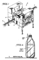
- Fig. 1 is a perspective view of an electronic container inspecting station incorporating the present invention;
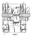
- Fig. 2 is a top view of the inspection station;
- Fig. 3 is a partial block and partial schematic electrical and optical circuit diagram illustrating the components of one of the inspection zones;
- Fig. 4 is a side view of a bottle illustrating an inspection window; and
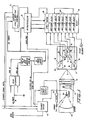
- Fig. 5 is a block circuit diagram of an amplifier and count selection circuit.
- In the following description of a preferred embodiment of the invention, particular reference is made to the inspection of glass bottles in order to facilitate an understanding of the invention. However, it will be appreciated that the invention is not limited to this specific application. Rather, it can find a variety of applications in the inspection of almost any type of article made from a transparent material.
- Referring to Figs. 1 and 2, bottles to be inspected are presented to an inspection station 10 in an upright position by means of a continuously moving
conveyor 12, such as a table-top chain. The inspection station 10 might be located downstream of an annealing/cooling lehr in a bottle manufacturing facility. Suitable means (not shown) can be provided upstream of the inspection station to space the bottles and thereby control container throughput into the inspection station. In addition, a downed bottle remover can be located immediately upstream of the inspection station to prevent fallen or stuck bottles from being conveyed into the inspection station. - Within the inspection station 10, the bottles first pass through an upstream inspection zone 14. At this location, the bottles are traversed by a vertically scanned laser beam that passes through a
slot 16 in a side wall of the inspection station cabinet adjacent the conveyor. The laser light passing through the bottle is collected on the opposite side of the conveyor and processed to determine whether any defects are present in the bottle. If a defect is detected, a reject signal is generated to cause the defective bottle to be removed from the conveyor. For example, the reject signal might actuate a solenoid that opens an air valve 18 located downstream of the inspection zone 14. When the valve is opened, pressurized air blows the rejected bottle off the conveyor into acullet chute 20, which carries the rejected bottle to a disposal location. - Although the laser beam scans the entire bottle as it passes through the inspection zone 14, it will be appreciated that the beginning and end of the scan of each bottle will not provide significant defect information since the beam will be highly attenuated as it passes through the leading and trailing surfaces of the bottle. Accordingly, it is desirable to limit defect detection to that portion of the bottle scan in which the beam passes through the front and back walls of the bottle, as viewed in the direction of propagation of the beam. For example, as explained in greater detail hereinafter, the
front 90° of circumference of the bottle and theback 90° of circumference might be inspected at the upstream zone 14. - If no defect is detected in the inspected portion of the bottle, it continues downstream on the
conveyor 12 to abottle rotator mechanism 22. The rotator mechanism includes a pair of spacedbelts movable carriages 28.Jacks 30 are located on the carriages to enable them to be moved toward and away from one another to accommodate bottles of different widths, as well as up and down to accommodate bottles of different heights. - The two belts are driven at different speeds, one being slightly faster than the speed of the
conveyor 12 and the other slightly slower, so as to rotate the bottle exactly 90° about its longitudinal axis as it travels at conveyor belt speed through the bottle rotator mechanism. Specifically, the speeds of thebelts 
where VB1 is the velocity of the faster belt, VB2 is the velocity of the slower belt, VC is the velocity of theconveyor 12, D is the diameter of the bottle and K is a constant related to the length of travel of the bottle as it is being rotated in the rotator mechanism. - The speeds of the motors which respectively drive the
belts - After having been rotated by 90°, the bottles are presented to a
downstream inspection zone 32 that is similar to the upstream zone 14. In this zone the bottles are scanned by a laser beam which is processed to detect faults in the portions of the bottle that were not inspected in the upstream location. If a fault is detected in this zone, asecond air valve 34 can be actuated by means of a reject signal to blow the faulty bottle into asecond cullet chute 36. If no defect is detected, theconveyor 12 carries the bottle away from the inspection station for further processing or filling. - Referring now to Fig. 3, the optical and electrical components for scanning the bottle and processing the light at one of the
zones 14 or 32 to detect a flaw are shown in greater detail. A similar arrangement is present in the other zone. The laser beam is generated by a suitable linearpolarized laser 40, such as a helium-neon laser. The output beam from this laser is reflected by amirror 42 to a self-resonant optical scanner 44. The scanner 44 basically comprises a planar mirror that is pivoted about an axis of rotation parallel to the direction of movement of the bottles. The pivoting of the mirror about the axis of rotation is carried out by means of ascanner driver 46 under the control of a scanner phase andamplitude control circuit 48. Preferably, the scanner phase control circuit coordinates the phase of the scanning laser beam to the electronic synchronization signals while the scanner amplitude control circuit maintains a constant scan amplitude. - The sinusoidal scanning beam that is reflected from the scanner mirror is directed onto a
spherical mirror 50 which reflects the scanning beam as parallel rays in a vertical plane. This plane is disposed transverse to the direction of movement of the bottle. The reflected beam passes through theslot 16 in the cabinet and traverses a vertical line along the bottle on theconveyor 12. - The laser light which passes through the bottle is projected onto a diffusing
screen 54 that can be made of flashed opal glass or plastic. In order to increase the sensitivity of the system, the laser light passing through the bottle is first collected on the side of the conveyor opposite the laser by a dual plano-convex lens set 52 and focussed upon the screen. Thescreen 54 forms the front of an essentially light-tight detection chamber 56. This chamber is divided into three cells by means ofpartitions light sensor 62 is located in each of the upper and lower cells to detect laser light which impinges on the portions of the screen corresponding to the location of these cells. The middle cell has threephotodiodes photodiodes 66 is mounted in atube 70 having a focusinglens 72 that is oriented on thefocal point 74 of the lens set 52 at the center of thescreen 54. Anotherphotodiode 68 in the central cell is provided with alaser line filter 76 which eliminates ambient lighting. - In operation, the scanner 44 can be operated at a frequency of about 800 Hz, for example, to scan a number of adjacent vertical traces on each bottle as it is being conveyed through an inspection zone. When the laser beam passes through the bottle essentially unimpeded, due to the absence of any defects, the
lens system 52 focusses the laser light upon thefocal point 74 at the center of the screen. However, if the beam strikes an imperfection within the bottle, it will either be blocked by the defect or it will be attenuated, dispersed, refracted, or reflected, or undergo some combination of these effects, in dependence upon the type of defect. The particular effect which the defect has on the beam will be detected by one or more of the photodiodes. - Each of the photodiodes 62-68 is connected to a
preamplifier 76 and the amplified signal therefrom is presented to one or more amplifier andcount selection circuits 78. In addition, the output signal from the filteredphotosensor 68 within the central cell is presented to a synchronization andcontrol circuit 80. Thecircuits photosensors circuits 78 that are connected to thephotosensors 62 in the outer cells are responsive to the presence of light. Thus, if the light beam passing through a bottle is dispersed or refracted, some or all of the light will be projected onto the outer portion of thescreen 54 where it will be detected by one or both of thephotodiodes 62 in the upper and lower cells. If the beam is blocked or highly attenuated, the absence of light in the center cell will be detected by one or more of thephotosensors central spot 74, which will be sensed by the focussedphotosensor 66. - The synchronization and
control circuit 80 and the amplifier andcount selection circuits 78 operate under the control of amicroprocessor 82 to compare the intensity of the light detected by each of the photosensors 62-68 to preselected threshold levels and to generate a reject signal when a threshold is crossed a predetermined number of times. In particular, the microprocessor selectively actuates each of the amplifier and count selection circuits in accordance with a specific, adjustable inspection window which encompasses a portion of the container surface. - Referring to Fig. 4, an example of a bottle that is to be inspected and the location of such a window thereon is shown. When the system is first initialized, a calibration model of known dimensions is conveyed through the inspection zones where it is scanned. The filtered
photosensor 68 in the central cell detects the influence of the edge of the model on the laser beam and provides a signal to the synchronization andcontrol circuit 80. This circuit passes the signal to the microprocessor, which processes it to determine the profile of the bottle. More particularly, each vertical excursion of the laser beam can be divided into a number of increments, e.g., 255 segments. For each excursion, the microprocessor determines during which increment of the excursion the detected light level of the incident beam changes by a predetermined amount, to ascertain the location of the edge of the bottle. After the bottle has been completely conveyed past theslot 16 so that it is scanned in its entirety, the microprocessor can determine a profile for the bottle and store it in memory. - During subsequent scans of bottles to be inspected, the microprocessor selectively enables and disables each of the amplifier and
count selection circuits 78 to define a dynamic window of inspection. This window is defined by vertical and horizontal parameters which can be selected by the operator. The vertical parameter can be expressed in terms of units of length, and the horizontal parameter is preferably expressed in terms of degrees of the bottle circumference. Referring to the example of Figure 4, the unshaded area in the central portion of the bottle represents the inspection window. Starting from the top of the bottle, this window might be defined as follows:
The microprocessor, in response to a scanner sync signal from thescanner driver circuit 46, which is indicative of the instantaneous angular orientation of the scanner mirror, disables the amplifier and count selection circuits during the portion of each scan in which the laser beam is in the shaded portion of the bottle and enables the circuits as the beam traverses the inspection window. - A separate window can be defined for each of the amplifier and count selection circuits so as to detect different types of faults in different areas of the bottle. Furthermore, as shown in Figure 4, each vertical trace of the scanning beam can be divided into a number of adjustable horizontal inspection bands. Thus, for example if it is known that the bottle is to be embossed in a certain area, the amplifier and count selection circuit or circuits which might detect this feature as a fault can be turned off as the beam scans that portion of the bottle. The inspection window for each of the
selection circuits 78 can be displayed on a CRT monitor or a printer for the convenience of the operator. - Referring to Figure 5, each of the amplifier and
count selection circuits 78 amplifies an incoming signal from one of the photodetectors in anamplifier 86 and compares its amplitude to a threshold value in acomparator 88. The gain of the amplifier can be user-adjusted by means of apotentiometer 90. Each time that the amplitude of the signal crosses the threshold during one vertical scan of the laser beam, a defect signal is generated and sent to a verticaloccurrence comparator circuit 92. This circuit is selectively enabled and disabled by the microprocessor in accordance with the inspection window. The vertical occurrence comparator circuit, in response to a scan signal from the microprocessor or from the scannerphase control circuit 48, counts the number of flaw signals that are generated during each vertical trace of the laser beam. If the number of detected flaws during a scan is equal to or greater than a user-selected count, thecomparator circuit 92 generates a signal which is presented to ahorizontal occurrence counter 94. Within the horizontal occurrence counter, the number of scans for which thecomparator circuit 92 generates a signal is counted and compared to a second user-selected count. If the number of counted scans equals or exceeds this second value, a signal is presented to areject circuit 96. Thereject circuit 96 issues a signal which is sent to a reject module 98 (Fig. 3) as well as counted in areject counter 100. Thereject counter 100 accumulates the number of bottles that are rejected by that selection circuit. - To provide the operator with an instantaneous indication of the status of the bottle analysis, the user-selected horizontal count value is converted to an analog signal in a digital-to-
analog converter 102 and presented as a reference signal to a bar graph driver anddisplay circuit 104. The actual count accumulated in thehorizontal occurrence counter 94 is also converted into an analog signal, by means of a second digital-to-analog converter 106, and presented to apeak detector 108. The peak detector selects the peak value of the accumulated count for each bottle and provides it as a data signal to the driver anddisplay circuit 104. This value is displayed on a bar display as a percentage of the reference count. Thus, when the accumulated count equals or exceeds the user-selected value, the bar graph will be fully illuminated to indicate that the bottle is being rejected. - The count which is determinative of a reject signal for each
selection circuit 78 can be generated in one of three different modes of operation. Two of these modes determine the presence of a defect on the basis of the number of vertical scans in which a flaw signal is generated, in either a consecutive or nonconsecutive fashion. In the consecutive mode, a defect signal must be generated at least once per scan for each of a preselected number of consecutive scans. Thus, in this mode the verticaloccurrence comparator circuit 92 provides a signal to the horizontal occurrence counter 94 only for each of two or more consecutive scans on which the user-selected count is equalled or exceeded. If the count is exceeded on one scan but not on the next, thecomparator circuit 92 sends a reset signal to thecounter 94. In the non-consecutive mode, it is only necessary that a flaw detection signal be generated during each of a predetermined number of scans across the window in order to cause a reject signal to be produced. Accordingly, in this mode each scan which results in the vertical count number being equalled or exceeded is indicated to thecounter 94, regardless of whether the scans are consecutive. If the inspection window for aparticular selection circuit 78 is divided into two vertically separated portions, it may be desirable to require that a flaw signal appear during the same portion of each of the scans, i.e. within the same section of a window, in order for a reject signal to be generated, thereby providing greater resolution. - In the third mode of operation, the total number of flaw signals that are generated is the determining factor, regardless of whether the flaw signals occurred during the same scan or on different scans. Thus, in this mode each flaw signal generated by the
comparator 88 is presented to thehorizontal occurrence counter 94 and counted therein. - As noted above and shown in Figure 4, it is possible to divide the inspection window into two or more horizontal bands by disabling the associated
count selection circuit 78 during a portion of each vertical trace of the laser beam. This may be necessary when the portion of the bottle contains certain features, e.g. a spiral design, which would be detected as a flaw. However, in some situations, it may be more desirable to inspect this portion of the bottle rather than blank out the inspection window in that area, yet account for design aspects of the bottle which might generate a flaw signal. This feature of the invention is accomplished by controlling the gain of the count selection circuit in accordance with the vertical position of the laser beam. To this end, the threshold value against which the incoming photosensor signal is compared can be adjusted under the control of the microprocessor. For example, the threshold might be established by means of a d.c. bias signal presented to one input terminal of thecomparator 88. The amplitude of this d.c. bias signal can be adjusted by the microprocessor during each vertical trace of the laser beam to increase the threshold level, and thereby decrease the sensitivity of the circuit, as the beam scans the portion of the bottle having a design feature such as a curve or knurl which could accidentally cause a flaw signal to be generated. - Alternatively, this same result can be provided by adjusting the gain of the
comparator 88 or the gain of thesignal amplifier 86. Thus, under microprocessor control the criterion for flaw signal generation can be dynamically adjusted during the scanning of the beam for eachindividual circuit 78 to enable bottles having different design features to be fully inspected. - In addition, the microprocessor can adjust the sensitivity of all of the
circuits photosensor 68. The amplitude of the detected light signal during this portion of the scan may decrease over time, for example due to the accumulation of dirt on the optical components and aging of the electrical components. This phenomenon can be detected in thecontrol circuit 80 and used by the microprocessor to adjust the sensitivity of all of the defect detection circuits. - The
reject module 98 controls the reject signal that is supplied to the solenoid for controlling one of theair valves 18 or 34. This module can be provided with delay and duration adjustments so that the time of generation and length of the reject signal is coordinated to the location and size of the defective bottle on the conveyor. The reject module 84 can also include a counter which accumulates the total number of containers rejected by the corresponding zone in the inspection station. - In the embodiment of the invention illustrated in Figure 3, five photosensors are shown connected to seven amplifier and count selection circuits respectively labelled 2-8 as well as to the synchronization and
control circuit 80. An example of the particular photodetector to which each of thecircuits 

- From the foregoing table, it will be appreciated that the present invention is capable of detecting a number of different types of flaws that are commonly encountered in transparent containers. Furthermore, the synchronization and
control circuit 80 can be used to inspect the bottles for dimensional defects. As each bottle passes through the inspection zone, the edge detection signals generated by thecontrol circuit 80 can be compared with those stored in memory. If a discrepancy exists due to improper bottle height, diameter or profile, e.g., a leaning bottle, a reject signal can be generated. Thecircuit 80 can also be used to count the total number of bottles that are processed. - In addition to rejecting defective bottles, the present invention provides the capability of supplying feedback information which can be used to isolate the source of a defect and thereby correct it to increase productivity. For example, if an inspection window is divided into a number of horizontal bands, the reject count which is accumulated in each of the
circuits 78 might be broken down in accordance with the particular band in which the flaws were detected. Thus, if the same type of flaw consistently occurs in the same area of each rejected bottle, statistical information regarding the containers rejected by each module can be used to spot a trend and used to ascertain the possible source of the flaw and correct it. - The preferred embodiment of the present invention can provide a novel system for automatically detecting defects in articles that are produced from transparent materials.
- The preferred embodiment of the invention can also provide such a system that is capable of detecting any and all of the various types of sidewall and dimensional defects that are commonly encountered in a transparent container with greater effectiveness than an average human inspector.
- The preferred embodiment of the present invention can further provide such a system that also offers the capability of isolating the location and type of defects found in containers to better enable the source of the defect to be corrected, and thereby increase productivity.
Claims (17)
- Apparatus for detecting defects in transparent articles, having a scanner (40, 42, 44, 50) for scanning a beam of light so that the beam traverses different portions of an article on successive scans; a plurality of photodetectors (62, 64, 66, 68) disposed adjacent a diffusing screen (54) for respectively detecting the intensity of light projected onto different predetermined areas of said screen (54); a threshold detector circuit (78, 80, 82) connected to said photodetectors (62, 64, 66, 68) for determining when the intensity of light detected by each of said photodetectors crosses respective thresholds; and a reject circuit (96, 98) responsive to said threshold detection for generating a reject signal; characterised by an optical element (52) for focusing light passing through the article onto said diffusing screen (54), said diffusing screen being located substantially at a focal point of said optical element (52).
- Apparatus as claimed in Claim 1, wherein the threshold detector circuit includes a threshold detection and counting circuit (70, 80, 82) connected to the photodetectors (62, 64, 66, 68) for determining the number of times the intensity of light detected by each of the photodetectors crosses respective thresholds, and the reject circuit (96, 98) responsive to the threshold detection and counting circuit is operable to generate a reject signal when said number of times is at least equal to a predetermined criterion value.
- Apparatus as claimed in Claim 1 or Claim 2, including a synchronizer (46) for synchronizing the threshold detection with the scanner so that said determination takes place only as the light beam traverses a predetermined portion of the article.
- Apparatus as claimed in any one of Claims 1 to 3, wherein the scanner (40, 42, 44, 50) is operable to scan the light beam in a first direction, and the conveyor (12) is operable to move the article relative to the scanned beam in a second direction so that the light beam traverses different portions of the article on successive scans.
- Apparatus as claimed in any one of Claims 1 to 4, further including a chamber (56) disposed adjacent to said screen (54), said chamber (56) being divided into a plurality of cells with at least one of said photodetectors (62, 64, 66, 68) being located in each cell.
- Apparatus as claimed in Claim 2, wherein the threshold detection and counting circuit includes a first subcircuit (78) for counting the number of times a threshold is crossed during each scan of the beam and a second subcircuit (92) for counting the number of scans during which the threshold is crossed.
- Apparatus as claimed in Claim 6, wherein said second subcircuit (92) counts the number of consecutive scans during which the threshold is crossed.
- Apparatus as claimed in Claim 6 or Claim 7, including a synchronizer (46) for synchronizing the counting circuit with the scanner in which the synchronizer (46) selectively enables one of said first and second counting subcircuit (78, 92) during scanning of the beam of light.
- Apparatus as claimed in any one of Claims 1 to 8, wherein the optical element includes a lens (52) for focussing all light which passes through an article unimpeded by a defect onto a predetermined area on the screen (54).
- Apparatus as claimed in Claim 6, wherein at least one of said threshold detectors (78) and an associated photodetector (64, 66, 68) is responsive to a decrease in the intensity of light projected onto said predetermined area on said screen (54) to generate a flaw signal, and another of said threshold detectors (78) is responsive to the projection of light onto a portion of the screen (54) outside of said area to generate a flaw signal.
- Apparatus as claimed in any one of Claims 1 to 10, further including a threshold varying circuit (82) for dynamically varying at least one of said thresholds during each scan of said beam in accordance with the portion of the article being scanned.
- Apparatus as claimed in any one of Claims 1 to 10, further including a threshold varying circuit (82) for adjusting said thresholds in response to changes in the detected intensity of the laser beam during a portion of its scan in which it does not pass through an article.
- Apparatus for inspecting a transparent container to detect the presence of a flaw, comprising:
means (12) for continuously moving a container along a path of travel;
a first inspection zone (14) including means (40, 42, 44, 50) for scanning a portion of the container with a beam of light, means (52) for collecting light passing through the container and focussing it upon a screen (54), means (62, 64, 66, 68, 78) for detecting the location and intensity of light focussed on the screen, and means (96, 98) for processing the detected light to generate a first reject signal;
container rotating means (22) located downstream of said first inspection zone (14) for rotating said container 90° about its longitudinal axis; and
a second inspection zone (32) located downstream of said rotating means (22) and including means for scanning a portion of the container with a beam of light, means for collecting light passing through the container and focussing it upon a screen, means for detecting the location and intensity of light focussed on the screen, and means for processing the detected light to generate a second reject signal. - Apparatus as claimed in Claim 13, wherein the container moving means is a conveyor (12) and the container rotating means (22) includes a pair of belts (24, 26) respectively disposed on opposite sides and parallel to the conveyor (12) for engaging a container as it passes between them on the conveyor, and means for moving one of said belts faster than said conveyor and moving the other of said belts slower than said conveyor so as to rotate the container as it moves at the speed of said conveyor.
- A method for detecting the presence of a fault in a transparent container which is scanned by a beam of light across the container, characterised in that light passing through the container is focussed onto a screen, the intensity of light falling on different predetermined portions of the screen is detected, the detected intensity is compared with a predetermined threshold, the number of times that the detected light intensity crosses the threshold during scanning of the beam is counted, and a signal indicating the presence of a fault is generated when said number of times is at least equal to a predetermined value, while the transparent container is continuously conveyed.
- A method as claimed in Claim 15, further including the step of synchronizing said comparing step with the scanning of the beam so that said comparing takes place only while said beam is traversing a predetermined area on the container.
- A method as claimed in Claim 15 or Claim 16, wherein said light is focussed onto the screen in a manner such that all light which passes through the container unaffected by a flaw is projected onto one portion of the screen and light which is refracted or dispersed by a flaw is projected onto another portion of the screen.
Priority Applications (1)
| Application Number | Priority Date | Filing Date | Title |
|---|---|---|---|
| AT85307690T ATE69884T1 (en) | 1984-12-27 | 1985-10-24 | ERROR DETECTION FOR CLEAR OBJECTS. |
Applications Claiming Priority (2)
| Application Number | Priority Date | Filing Date | Title |
|---|---|---|---|
| US06/686,525 US4655349A (en) | 1984-12-27 | 1984-12-27 | System for automatically inspecting transparent containers for sidewall and dimensional defects |
| US686525 | 1984-12-27 |
Publications (3)
| Publication Number | Publication Date |
|---|---|
| EP0186278A2 EP0186278A2 (en) | 1986-07-02 |
| EP0186278A3 EP0186278A3 (en) | 1986-08-20 |
| EP0186278B1 true EP0186278B1 (en) | 1991-11-27 |
Family
ID=24756670
Family Applications (1)
| Application Number | Title | Priority Date | Filing Date |
|---|---|---|---|
| EP85307690A Expired - Lifetime EP0186278B1 (en) | 1984-12-27 | 1985-10-24 | Detecting defects in transparent articles |
Country Status (15)
| Country | Link |
|---|---|
| US (1) | US4655349A (en) |
| EP (1) | EP0186278B1 (en) |
| JP (1) | JPS61200449A (en) |
| AT (1) | ATE69884T1 (en) |
| AU (1) | AU583556B2 (en) |
| BR (1) | BR8506514A (en) |
| CA (1) | CA1244915A (en) |
| DE (1) | DE3584768D1 (en) |
| DK (2) | DK168314B1 (en) |
| ES (3) | ES8800431A1 (en) |
| FI (1) | FI854593A (en) |
| IN (1) | IN165168B (en) |
| MX (1) | MX160021A (en) |
| NO (1) | NO854636L (en) |
| ZA (1) | ZA858453B (en) |
Cited By (1)
| Publication number | Priority date | Publication date | Assignee | Title |
|---|---|---|---|---|
| CN109475906A (en) * | 2016-08-12 | 2019-03-15 | 亚马逊技术股份有限公司 | Object sensing and processing system and correlation technique |
Families Citing this family (30)
| Publication number | Priority date | Publication date | Assignee | Title |
|---|---|---|---|---|
| US4679075A (en) * | 1985-04-29 | 1987-07-07 | Emhart Industries, Inc. | Glassware inspection using optical streak detection |
| ZA875450B (en) * | 1986-07-28 | 1988-04-27 | Saint Gobain Cinematique | Inspection of transparent bodies |
| US4804274A (en) * | 1986-12-30 | 1989-02-14 | Mobil Oil Corporation | Method and apparatus for determining phase transition temperature using laser attenuation |
| US5007096A (en) * | 1987-02-18 | 1991-04-09 | Hajime Industries Ltd. | Object inspection apparatus |
| JPS63304146A (en) * | 1987-06-04 | 1988-12-12 | Kirin Brewery Co Ltd | Inspecting device for drum part of bottle |
| US4874940A (en) * | 1988-01-11 | 1989-10-17 | Brockway, Inc. (N.Y.) | Method and apparatus for inspection of a transparent container |
| JPH0627717B2 (en) * | 1988-04-13 | 1994-04-13 | 株式会社キリンテクノシステム | Bottle body inspection device |
| FR2649485B1 (en) * | 1989-07-10 | 1992-10-16 | Vega | DEVICE FOR CONTROLLING THE APPEARANCE OF THE OUTSIDE SURFACE OF OBJECTS |
| US5144124A (en) * | 1990-11-19 | 1992-09-01 | Emhart Industries, Inc. | Glass container inspection machine with plot display of container and light intensity |
| JP2893078B2 (en) * | 1990-12-06 | 1999-05-17 | オムロン株式会社 | Shading correction method and device |
| JP2807946B2 (en) * | 1992-07-10 | 1998-10-08 | 三共株式会社 | Gusset packaging bag folding failure detection method |
| JP3044961B2 (en) * | 1993-02-12 | 2000-05-22 | 富士電機株式会社 | Circular container inner surface inspection device |
| US5422476A (en) * | 1993-09-15 | 1995-06-06 | Emhart Glass Machinery Investments Inc. | Glass container inspection machine |
| WO1996018883A1 (en) * | 1994-12-13 | 1996-06-20 | Kjærgaard Industri Automatic A/S | A method and an apparatus for identifying foreign bodies in packaged beverages, as well as use of the apparatus |
| US5608207A (en) * | 1995-05-23 | 1997-03-04 | Honeywell Inc. | Sensor with automatic gain control |
| DE19605133C2 (en) * | 1996-02-13 | 2000-06-15 | Krones Ag | Inspection machine for vessels |
| US5708278A (en) * | 1996-05-13 | 1998-01-13 | Johnson & Johnson Clinical Diagnostics, Inc. | Reflective wetness detector |
| FR2788490B1 (en) * | 1999-01-19 | 2001-03-30 | Sparflex | METHOD OF ORIENTATION OF A BOTTLE HAVING A RELIEF PATTERN ON ITS NECK AND DEVICE FOR IMPLEMENTING IT |
| AU2751101A (en) * | 1999-11-05 | 2001-05-30 | Midas Vision Sysems, Inc. | Via inspection in optical inspection system |
| US6583405B2 (en) * | 2000-08-16 | 2003-06-24 | Vince Walbe | Glass breakage detection using gas discharge lighting |
| FR2818442B1 (en) * | 2000-12-20 | 2003-10-17 | Energy Systems Internat Bv | WINDOW-FORMING PHOTOVOLTAIC DEVICE |
| US6943877B2 (en) * | 2003-06-30 | 2005-09-13 | Emhart Glass S.A. | Container inspection machine |
| US7073877B2 (en) * | 2003-06-30 | 2006-07-11 | Emhart Glass S.A. | Container inspection machine |
| US7342654B2 (en) * | 2003-12-19 | 2008-03-11 | International Business Machines Corporation | Detection of impurities in cylindrically shaped transparent media |
| NO322775B1 (en) * | 2004-09-24 | 2006-12-11 | Tomra Systems Asa | Device and method for detecting a medium |
| US7148961B1 (en) | 2004-11-10 | 2006-12-12 | Owens-Brockway Glass Container Inc. | Container sidewall inspection |
| DE102012009783B3 (en) * | 2012-05-18 | 2013-08-14 | Khs Gmbh | Method and device for inspection of empty bottles |
| CN104422479A (en) * | 2013-08-27 | 2015-03-18 | 深圳市安瑞科科技有限公司 | Medicine bottle laser detection circuit |
| US10012598B2 (en) | 2015-07-17 | 2018-07-03 | Emhart S.A. | Multi-wavelength laser check detection tool |
| US10712314B2 (en) * | 2017-09-12 | 2020-07-14 | Tenaris Connections B.V. | Pipe inspection |
Family Cites Families (16)
| Publication number | Priority date | Publication date | Assignee | Title |
|---|---|---|---|---|
| US3411009A (en) * | 1964-10-05 | 1968-11-12 | Fords Fensbury Ltd | Radiation sensitive apparatus for detecting dirt in transparent bottles |
| US3356853A (en) * | 1965-01-04 | 1967-12-05 | Owens Illinois Glass Co | Radiation sensitive apparatus for inspecting the bottom wall of hollow transparent containers |
| US3770969A (en) * | 1972-03-09 | 1973-11-06 | Owens Illinois Inc | Inspecting the bottom wall of hollow open-ended containers |
| US4076424A (en) * | 1976-03-24 | 1978-02-28 | E. I. Du Pont De Nemours And Company | Multi-channel implicit ratio computer for sequential signals |
| JPS5848829B2 (en) * | 1976-07-31 | 1983-10-31 | 石川島播磨重工業株式会社 | Reduction furnace discharge device |
| JPS5342093A (en) * | 1976-09-28 | 1978-04-17 | Mitsubishi Electric Corp | Tester for glass bottle |
| US4165277A (en) * | 1977-02-25 | 1979-08-21 | Inex, Incorporated | Article monitoring and reject apparatus |
| GB1600400A (en) * | 1977-10-13 | 1981-10-14 | Ti Fords Ltd | Bottle inspection apparatus |
| IE47919B1 (en) * | 1979-02-26 | 1984-07-25 | Udaras Na Gaeltachta | Apparatus for inspecting translucent articles for faults |
| DE3028942A1 (en) * | 1980-07-30 | 1982-02-18 | Krones Ag Hermann Kronseder Maschinenfabrik, 8402 Neutraubling | METHOD AND INSPECTION DEVICE FOR INSPECTING AN OBJECT, IN PARTICULAR A BOTTLE |
| US4378494A (en) * | 1980-11-07 | 1983-03-29 | Owens-Illinois, Inc. | Apparatus and method for detecting defects in glass bottles using event proximity |
| US4513868A (en) * | 1981-01-19 | 1985-04-30 | Gunson's Sortex Limited | Sorting machine |
| US4492476A (en) * | 1981-02-20 | 1985-01-08 | Kirin Beer Kabushiki Kaisha | Defect detecting method and apparatus |
| US4385233A (en) * | 1981-03-18 | 1983-05-24 | Owens-Illinois, Inc. | Fused glass detector |
| JPS57201839A (en) * | 1981-06-08 | 1982-12-10 | Suntory Ltd | Inspection method of bottles |
| JPS5821146A (en) * | 1981-07-30 | 1983-02-07 | Kirin Brewery Co Ltd | Method and device for inspection of defect |
-
1984
- 1984-12-27 US US06/686,525 patent/US4655349A/en not_active Expired - Lifetime
-
1985
- 1985-10-24 IN IN884/DEL/85A patent/IN165168B/en unknown
- 1985-10-24 DE DE8585307690T patent/DE3584768D1/en not_active Expired - Lifetime
- 1985-10-24 EP EP85307690A patent/EP0186278B1/en not_active Expired - Lifetime
- 1985-10-24 AT AT85307690T patent/ATE69884T1/en active
- 1985-11-04 ZA ZA858453A patent/ZA858453B/en unknown
- 1985-11-20 NO NO854636A patent/NO854636L/en unknown
- 1985-11-21 FI FI854593A patent/FI854593A/en not_active IP Right Cessation
- 1985-11-28 AU AU50489/85A patent/AU583556B2/en not_active Ceased
- 1985-12-20 JP JP60285849A patent/JPS61200449A/en active Pending
- 1985-12-23 DK DK601485D patent/DK168314B1/en not_active IP Right Cessation
- 1985-12-23 DK DK601485A patent/DK601485A/en not_active IP Right Cessation
- 1985-12-24 CA CA000498555A patent/CA1244915A/en not_active Expired
- 1985-12-26 ES ES550416A patent/ES8800431A1/en not_active Expired
- 1985-12-26 BR BR8506514A patent/BR8506514A/en not_active IP Right Cessation
- 1985-12-27 MX MX1111A patent/MX160021A/en unknown
-
1987
- 1987-06-30 ES ES557612A patent/ES8801032A1/en not_active Expired
- 1987-06-30 ES ES557611A patent/ES8900065A1/en not_active Expired
Cited By (1)
| Publication number | Priority date | Publication date | Assignee | Title |
|---|---|---|---|---|
| CN109475906A (en) * | 2016-08-12 | 2019-03-15 | 亚马逊技术股份有限公司 | Object sensing and processing system and correlation technique |
Also Published As
| Publication number | Publication date |
|---|---|
| ES550416A0 (en) | 1987-11-01 |
| ATE69884T1 (en) | 1991-12-15 |
| MX160021A (en) | 1989-11-07 |
| AU5048985A (en) | 1986-07-03 |
| US4655349A (en) | 1987-04-07 |
| BR8506514A (en) | 1986-09-02 |
| ES8800431A1 (en) | 1987-11-01 |
| DK601485A (en) | 1986-06-28 |
| DK168314B1 (en) | 1994-03-07 |
| ES8801032A1 (en) | 1987-12-01 |
| EP0186278A3 (en) | 1986-08-20 |
| NO854636L (en) | 1986-06-30 |
| ES8900065A1 (en) | 1988-11-16 |
| ZA858453B (en) | 1986-07-30 |
| ES557612A0 (en) | 1987-12-01 |
| IN165168B (en) | 1989-08-19 |
| FI854593A0 (en) | 1985-11-21 |
| CA1244915A (en) | 1988-11-15 |
| DE3584768D1 (en) | 1992-01-09 |
| FI854593A (en) | 1986-06-28 |
| JPS61200449A (en) | 1986-09-05 |
| EP0186278A2 (en) | 1986-07-02 |
| ES557611A0 (en) | 1988-11-16 |
| AU583556B2 (en) | 1989-05-04 |
| DK601485D0 (en) | 1985-12-23 |
Similar Documents
| Publication | Publication Date | Title |
|---|---|---|
| EP0186278B1 (en) | Detecting defects in transparent articles | |
| JPH02247506A (en) | Method for inspecting good by optical process | |
| EP0324285B1 (en) | Method of and apparatus for inspection of a transparent container | |
| CA1065436A (en) | Method and apparatus for video inspection of articles of manufacture | |
| US4391373A (en) | Method of and apparatus for compensating signal drift during container inspection | |
| US4488648A (en) | Flaw detector | |
| US4483615A (en) | Method and apparatus for detecting checks in glass tubes | |
| US4553217A (en) | Glassware gauging system | |
| CA1258656A (en) | Inspecting and sorting of glass containers | |
| CN1110063A (en) | Apparatus for the detection of surface defects | |
| US3427109A (en) | Reflection testing apparatus which detects pits in sheet material | |
| WO2002033390A1 (en) | Method and apparatus for detecting refractive defects in transparent containers | |
| CA2628649C (en) | Apparatus and method for ensuring rotation of a container during inspection | |
| US4487322A (en) | Method for inspecting glass containers | |
| US4170417A (en) | Apparatus and method for optical control of the profile of a body utilizing a planar laser beam | |
| US5991017A (en) | Inspecting the surface of an object | |
| EP0193403A1 (en) | Birdswing defect detection for glass containers | |
| US3415370A (en) | Empty bottle bottom and neck inspection machine using radiation sensitive means | |
| US4385233A (en) | Fused glass detector | |
| US3180994A (en) | Method and apparatus for inspecting glass containers | |
| US4850491A (en) | Apparatus for control of a wooden article | |
| JPH09318559A (en) | Visual inspection method for transparent glass container and apparatus therefor | |
| EP2186576B1 (en) | Method and device for sorting products | |
| JPS5860244A (en) | Method of inspecting transparent material strip | |
| DE4400179A1 (en) | System for verifying presence of vacuum in drinks or food container |
Legal Events
| Date | Code | Title | Description |
|---|---|---|---|
| PUAI | Public reference made under article 153(3) epc to a published international application that has entered the european phase |
Free format text: ORIGINAL CODE: 0009012 |
|
| PUAL | Search report despatched |
Free format text: ORIGINAL CODE: 0009013 |
|
| AK | Designated contracting states |
Kind code of ref document: A2 Designated state(s): AT BE CH DE FR GB IT LI LU NL SE |
|
| AK | Designated contracting states |
Kind code of ref document: A3 Designated state(s): AT BE CH DE FR GB IT LI LU NL SE |
|
| 17P | Request for examination filed |
Effective date: 19870203 |
|
| 17Q | First examination report despatched |
Effective date: 19880721 |
|
| GRAA | (expected) grant |
Free format text: ORIGINAL CODE: 0009210 |
|
| AK | Designated contracting states |
Kind code of ref document: B1 Designated state(s): AT BE CH DE FR GB IT LI LU NL SE |
|
| PG25 | Lapsed in a contracting state [announced via postgrant information from national office to epo] |
Ref country code: SE Effective date: 19911127 Ref country code: NL Effective date: 19911127 Ref country code: LI Effective date: 19911127 Ref country code: FR Effective date: 19911127 Ref country code: CH Effective date: 19911127 Ref country code: BE Effective date: 19911127 Ref country code: AT Effective date: 19911127 |
|
| REF | Corresponds to: |
Ref document number: 69884 Country of ref document: AT Date of ref document: 19911215 Kind code of ref document: T |
|
| REF | Corresponds to: |
Ref document number: 3584768 Country of ref document: DE Date of ref document: 19920109 |
|
| ITF | It: translation for a ep patent filed |
Owner name: BARZANO' E ZANARDO ROMA S.P.A. |
|
| REG | Reference to a national code |
Ref country code: CH Ref legal event code: PL |
|
| EN | Fr: translation not filed | ||
| NLV1 | Nl: lapsed or annulled due to failure to fulfill the requirements of art. 29p and 29m of the patents act | ||
| RAP2 | Party data changed (patent owner data changed or rights of a patent transferred) |
Owner name: OWENS-BROCKWAY GLASS CONTAINER INC. |
|
| PLBE | No opposition filed within time limit |
Free format text: ORIGINAL CODE: 0009261 |
|
| STAA | Information on the status of an ep patent application or granted ep patent |
Free format text: STATUS: NO OPPOSITION FILED WITHIN TIME LIMIT |
|
| PG25 | Lapsed in a contracting state [announced via postgrant information from national office to epo] |
Ref country code: GB Effective date: 19921024 |
|
| PG25 | Lapsed in a contracting state [announced via postgrant information from national office to epo] |
Ref country code: LU Free format text: LAPSE BECAUSE OF NON-PAYMENT OF DUE FEES Effective date: 19921031 |
|
| 26N | No opposition filed | ||
| GBPC | Gb: european patent ceased through non-payment of renewal fee |
Effective date: 19921024 |
|
| PG25 | Lapsed in a contracting state [announced via postgrant information from national office to epo] |
Ref country code: DE Effective date: 19930701 |