EP2185458B1 - Device for driving a door of an elevator - Google Patents
Device for driving a door of an elevator Download PDFInfo
- Publication number
- EP2185458B1 EP2185458B1 EP08828623A EP08828623A EP2185458B1 EP 2185458 B1 EP2185458 B1 EP 2185458B1 EP 08828623 A EP08828623 A EP 08828623A EP 08828623 A EP08828623 A EP 08828623A EP 2185458 B1 EP2185458 B1 EP 2185458B1
- Authority
- EP
- European Patent Office
- Prior art keywords
- door
- driving
- vertical portion
- rotating shaft
- motor
- Prior art date
- Legal status (The legal status is an assumption and is not a legal conclusion. Google has not performed a legal analysis and makes no representation as to the accuracy of the status listed.)
- Active
Links
Images




Classifications
-
- B—PERFORMING OPERATIONS; TRANSPORTING
- B66—HOISTING; LIFTING; HAULING
- B66B—ELEVATORS; ESCALATORS OR MOVING WALKWAYS
- B66B13/00—Doors, gates, or other apparatus controlling access to, or exit from, cages or lift well landings
- B66B13/02—Door or gate operation
- B66B13/06—Door or gate operation of sliding doors
- B66B13/08—Door or gate operation of sliding doors guided for horizontal movement
-
- B—PERFORMING OPERATIONS; TRANSPORTING
- B66—HOISTING; LIFTING; HAULING
- B66B—ELEVATORS; ESCALATORS OR MOVING WALKWAYS
- B66B13/00—Doors, gates, or other apparatus controlling access to, or exit from, cages or lift well landings
- B66B13/02—Door or gate operation
- B66B13/06—Door or gate operation of sliding doors
Definitions
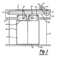
- Fig. 1 is a front elevation view illustrating a conventional elevator car
- Fig. 2 is a side view showing the car door apparatus in Fig. 1 , with car body 1 being shown in cross-section.
- elevator car entrance 2 is provided at the front face of car body 1.
- Door frame 3 extends along the width of entrance 2, and is fixed to car body 1 above entrance 2.
- Door motor 4 having motor pulley 5 is mounted on door frame 3.
- Reduction pulley 6 having a larger diameter than motor pulley 5 has belt 7 wound between motor pulley 5 and reduction pulley 6.
- Drive pulley 8 has a smaller diameter than and is coaxial with reduction pulley 6, can be rotated integrally with the reduction pulley 6.
- Following pulley 9 is provided at the door frame 3, with second belt 10 wound between drive pulley 8 and following pulley 9.
- Door rail 11 extends along the width direction of entrance 2 and is attached to door frame 3.
- Two car doors 12 are suspended from door rail 11 through door hangers 13.
- Each door hanger 13 has two rollers 14 which are rotated along door rail 11.
- Car doors 12 are connected to second belt 10 through door hanger 13 and belt holders 15 and 16.
- a plurality of door shoes 17 are attached adjacent the lower edge of each of doors 12.
- Door shoes 17 are inserted into a groove (not shown) of sill 18 disposed at the lower portion of entrance 2.
- car body 1 is provided with upper panel 19 and ceiling panel 20.
- motor pulley 5 is rotated by door motor 4, and the rotation is transmitted to reduction pulley 6 through reduction belt 7.
- Drive pulley 8 is rotated with reduction pulley 6, and thus second belt 10 is circulated and following pulley 9 is rotated.
- door hangers 13 are connected to belt 10, door hangers 13 and doors 12 are reciprocated along door rail 11 by the circulation of second belt 10 to open or close entrance 2. Doors 12 are suspended from door rail 11 and the bottom portions of doors 12 are guided by the sill groove of sill 18 during the opening and the closing of doors 12.
- Figs. 1 and 2 show a prior art device for driving a door of an elevator car, wherein door motor 4 is located above car body 1 and ceiling plate 20 of car body 1 is placed just below door motor 4.
- ceiling plate 20 cannot help but interfere with door motor 4. Accordingly, the door driving device must be redesigned in order to avoid such interference. Further, large noise may occur in such a door driving device due to reduction pulley 6 and reduction belt 7 during the movement of doors 12.
- Figs. 3 and 4 show another prior art device for driving doors 2 of elevator car 1, wherein door motor 22 is disposed under horizontal portion 21 b of a door frame 21 inside plane A extending parallel to vertical end face 18b of a sill, thereby eliminating interference between door motor 22 and ceiling plate 20.
- bolts 23 hold door motor 22 in place on horizontal portion 21b of door frame 21, while vertical portion 21a extends down to attach to rail 11.
- Driving pulley 24 is attached to drive motor 22, and connected to following pulley 25 via belt 26.
- Rail 11 extends along the width of car 1, with door hangers 13 and corresponding rollers 14 being supported thereon.
- Doors 12 are connected to belt 26 through door hangers 13 and belt holders 15 and 16.
- Door shoes 17 are attached adjacent lower edge of doors 12, and are inserted into groove 18a of sill 18. The door operates as described before, with the exception being that drive motor is connected directly to driving pulley 24 without a reduction mechanism.
- a driving motor which is configured to cause less vibration and noise, is necessary for driving a door of an elevator. Further, a device for driving a door of an elevator that does not interfere with a ceiling plate of an elevator and is compactly configured is needed.
- the present invention aims to resolve one or more of the aforementioned issues that afflict elevator systems.
- a device for driving elevator doors and having the features of the preamble of claim 1 is disclosed in JP 2007-153495 A1 .
- a further device for driving elevator doors is disclosed in JP 2004-1982 A1 .
- the present invention provides a device for driving a door of an elevator, which device is as set forth in claim 1.
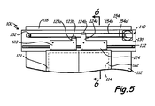
- FIG. 5 is a front elevation view of a portion of an embodiment of an elevator car.
- FIG. 6 is a cross-sectional view of a portion of the car shown in FIG. 5 .
- Illustrated in FIGS. 5 and 6 are elevator door driving device 100, elevator car 110, frame 112, doorway 114, ceiling plate 116, doors 121 and 122, door hangers 123 and 124 having upper portions 123a and 124a and belt holders 123b and 124b, upper roller 125b, lower roller 126b, door header 130 with vertical portion 130a, horizontal portion 130b, and bent section 130c, rail 132, driving motor 140, driven pulley 152, and belt 154 having lower portion 154a and upper portion 154b.
- elevator door driving device 100 is configured to be disposed at elevator car 110 to drive doors 121 and 122.
- Elevator door driving device 100 has door header 130 mounted above doorway 114 of elevator car 110; door rail 132 provided on door header 130 for supporting upper sides of doors 121 and 122; driving motor 140 disposed on door header 130 above door rail 132 and having driving pulley (not shown) therein; driven (or following or idler) pulley 152 rotatably provided on door header 130 as being apart from driving pulley; and drive belt 154 wound around driving pulley and driven pulley 152 along a lengthwise direction of door header 130.
- Drive belt 154 is a continuous piece of material, such as a rubber strap or rope.
- Doors 121 and 122 each contain door hanger 123 and 124, respectively, which attach doors 121 and 122 to drive belt 154.
- Upper portion 123a of door hanger 123 contains belt holder 123b for attaching to lower portion 154a of drive belt 154
- upper portion 124a of door hanger 124 contains belt holder 124b for attaching to upper portion 154b of drive belt 154.
- Belt holders 123b and 124b are pulleys, sheaves, or similar wheels with a slot or similar surface for receiving drive belt 154, and may be constructed from metal, polymers, or similarly rigid materials.
- Door hanger 124 also has upper roller 125b and lower roller 126b that engage rail 132 to provide smooth motion for the operation of door 122.
- Rollers 125b and 126b are wheels or similarly round structures with a surface for engaging rail 132, and may be constructed from metal, polymers, resilient material, or any combination thereof.
- upper roller 125b is a pulley or sheave with outer lips that extend past the engagement surface of rail 132
- lower roller 126b is a wheel having a rim covered by a resilient material to engage rail 132 to dampen vibrations and other resultant forces during operation of door 122.
- Door hanger 123 contains similar corresponding structures.
- Elevator car 110 includes frame 112 defining doorway 114. A portion of ceiling plate 116 is attached to an upper side of frame 112.
- Door header 130 includes vertical portion 130a substantially parallel to doorway 114, and horizontal portion 130b extending from an upper end of vertical portion 130a. Horizontal portion 130b may be omitted.
- Driving motor 140 is mounted on vertical portion 130a of door header 130 above door rail 132.
- Door header may contain bent section 130c that secures and spaces the position of door rail 132 with respect to driving motor 140.
- FIG. 7 is a perspective view of an embodiment of a motor for driving an elevator door
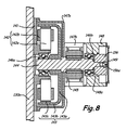
- FIG. 8 is a cross-sectional view of the motor illustrated in FIG. 7
- Illustrated in FIGS. 7 and 8 are vertical portion 130a, driving motor 140, cover 141, fastener 141 a, stator portion 142 with core 142a and coil 142b, rotor portion 143 with disk portion 143a, rim portion 143b, and magnet 143c, rotating shaft 144, driving pulley 145, bearings 146a and 146b, first housing 147 with rotor cover 147a, inner connection 147b, and outer connection 147c, second housing 148 with inner portion 148a, fasteners 148b, cover plate 149, and transducer 156 with rotor 156a.
- FIGS. 7 and 8 show driving motor 140, which has first and second housings 147 and 148 fixed with respect to vertical portion 130a; rotating shaft 144 oriented perpendicularly to vertical portion 130a and being rotatably supported at both its ends; driving pulley 145 coupled to rotating shaft 144; and a driving portion formed of stator 142 and rotor portion 143 for driving rotating shaft 144.
- Cover 141 is provided between vertical portion 130a and first housing 147, and is secured to vertical portion 130a via fasteners such as 141a.
- First housing 147 contains rotor cover 147a, inner connection 147b and outer connection 147c.
- Second housing 148 is attached to inner connection 147b and outer connection 147c through fasteners 148b, which may be machine screws, bolts, or similar structures.
- Second housing 148 may contain cover plate 149 that is generally parallel to cover 141.
- Cover plate 149, first and second housings 147, 148, and cover 141 may be constructed from sheet metal, cast alloys or metals, or polymers.
- transducer 156 Also attached to shaft 144 is transducer 156, which may be either an encoder or resolver, secured by inner portion 148a of second housing 148.
- transducer 156 is a resolver with rotor 156a surrounded by stator windings.
- the driving portion has stator portion 142 radially disposed about rotating shaft 144 and rotor portion 143 relatively rotated with respect to stator portion 142 by a magnetic force.
- Stator portion 142 includes a plurality of cores 142a and coils 142b wound around respective cores 142a.
- Rotor portion 143 includes: disk portion 143a with a central hole; rim portion 143b extending from an edge of disk portion 143a; and a plurality of magnets 143c attached on an inner periphery of rim portion 143b.
- First housing 147 is fixed to vertical portion 130a via the cover 141 while surrounding stator portion 142 and rotor portion 143.
- Second housing 148 is fixed to first housing 147 with driving pulley 145 interposed therebetween.
- Driving motor 140 further has first bearing 146a fixed to cover 141, and second bearing 146b disposed at second housing 148. One end portion and the other end portion of rotating shaft 144 are fitted to first bearing 146a and second
- elevator door driving device 100 can be easily applied without any redesign thereof even when designing an elevator car with higher ceiling plate 116.
- rotating shaft 144 since the one end of rotating shaft 144 is fitted to first bearing 146a, which is supported with respect to vertical portion 130a via cover 141, vertical portion 130a can directly support rotating shaft 144. Therefore, driving motor 140 can be more stably operated while making less vibration. Further, since rotating shaft 144 is rotatably supported via first and second bearings 146a, 146b at both its ends, the load applied to driving pulley 145 during operation of elevator door driving device 100 can be more stably supported. Thus, vibration and noise occurring during movement of doors 121 and 122 can be remarkably reduced, thereby providing a faster driving of doors 121 and 122.
- rotor portion 143 and driving pulley 145 are coupled to rotating shaft 144 in a lengthwise direction thereof.
- driving motor 140 can be transmitted to driving pulley 145 without any loss and driving motor 140 can be configured more compactly.
- the orientation of rotor 143 having disk 143a located outside of bearing 146a instead of adjacent vertical portion 130a provides the advantage of further stability of motor 140.
- prior art motors place the disk portion on the end of shaft 144, next to vertical portion 130a and inside of bearing 146; such a prior art arrangement produces more imbalance in the rotor due to the cantilevered positioning, as well as provides less protection for the motor from outside vibrations on header 130.
- the current arrangement with cover plate 141 and first housing 147 provide better protection from foreign particles, such as dust or water, during assembly and operation of the motor compared to prior art designs.
Landscapes
- Elevator Door Apparatuses (AREA)
- Forklifts And Lifting Vehicles (AREA)
- Automobile Manufacture Line, Endless Track Vehicle, Trailer (AREA)
Abstract
Description
-
Fig. 1 is a front elevation view illustrating a conventional elevator car, andFig. 2 is a side view showing the car door apparatus inFig. 1 , withcar body 1 being shown in cross-section. As illustrated,elevator car entrance 2 is provided at the front face ofcar body 1.Door frame 3 extends along the width ofentrance 2, and is fixed tocar body 1 aboveentrance 2. Doormotor 4 having motor pulley 5 is mounted ondoor frame 3. Reduction pulley 6 having a larger diameter than motor pulley 5 has belt 7 wound between motor pulley 5 and reduction pulley 6.Drive pulley 8 has a smaller diameter than and is coaxial with reduction pulley 6, can be rotated integrally with the reduction pulley 6. Following pulley 9 is provided at thedoor frame 3, withsecond belt 10 wound betweendrive pulley 8 and following pulley 9. -
Door rail 11 extends along the width direction ofentrance 2 and is attached todoor frame 3. Twocar doors 12 are suspended fromdoor rail 11 throughdoor hangers 13. Eachdoor hanger 13 has tworollers 14 which are rotated alongdoor rail 11.Car doors 12 are connected tosecond belt 10 throughdoor hanger 13 andbelt holders door shoes 17 are attached adjacent the lower edge of each ofdoors 12.Door shoes 17 are inserted into a groove (not shown) ofsill 18 disposed at the lower portion ofentrance 2. Further,car body 1 is provided withupper panel 19 andceiling panel 20. - During operation, motor pulley 5 is rotated by
door motor 4, and the rotation is transmitted to reduction pulley 6 through reduction belt 7.Drive pulley 8 is rotated with reduction pulley 6, and thussecond belt 10 is circulated and following pulley 9 is rotated. - Since
door hangers 13 are connected tobelt 10,door hangers 13 anddoors 12 are reciprocated alongdoor rail 11 by the circulation ofsecond belt 10 to open orclose entrance 2.Doors 12 are suspended fromdoor rail 11 and the bottom portions ofdoors 12 are guided by the sill groove ofsill 18 during the opening and the closing ofdoors 12. -
Figs. 1 and2 show a prior art device for driving a door of an elevator car, whereindoor motor 4 is located abovecar body 1 andceiling plate 20 ofcar body 1 is placed just belowdoor motor 4. When designing the elevator car withhigher ceiling plate 20, which is equipped with such a door driving device,ceiling plate 20 cannot help but interfere withdoor motor 4. Accordingly, the door driving device must be redesigned in order to avoid such interference. Further, large noise may occur in such a door driving device due to reduction pulley 6 and reduction belt 7 during the movement ofdoors 12. -
Figs. 3 and4 show another prior art device for drivingdoors 2 ofelevator car 1, whereindoor motor 22 is disposed underhorizontal portion 21 b of adoor frame 21 inside plane A extending parallel tovertical end face 18b of a sill, thereby eliminating interference betweendoor motor 22 andceiling plate 20. In this embodiment, bolts 23hold door motor 22 in place onhorizontal portion 21b ofdoor frame 21, whilevertical portion 21a extends down to attach to rail 11. Drivingpulley 24 is attached to drivemotor 22, and connected to followingpulley 25 viabelt 26.Rail 11 extends along the width ofcar 1, withdoor hangers 13 andcorresponding rollers 14 being supported thereon.Doors 12 are connected to belt 26 throughdoor hangers 13 andbelt holders Door shoes 17 are attached adjacent lower edge ofdoors 12, and are inserted intogroove 18a ofsill 18. The door operates as described before, with the exception being that drive motor is connected directly to drivingpulley 24 without a reduction mechanism. - However, since a driving shaft of
door motor 22 is not directly supported bydoor frame 21, vibrations caused by the rotation of the driving shaft can be applied todoor frame 21 during operation ofdoor motor 22. Further, since the distal end of the driving shaft, to which drivingpulley 24 is coupled, serves as a free end, the load applied to drivingpulley 24 throughbelt 26 during movement ofdoors 12 cannot be smoothly supported, thereby causing vibrations and noise. - Accordingly, a driving motor, which is configured to cause less vibration and noise, is necessary for driving a door of an elevator. Further, a device for driving a door of an elevator that does not interfere with a ceiling plate of an elevator and is compactly configured is needed.
- In light of the foregoing, the present invention aims to resolve one or more of the aforementioned issues that afflict elevator systems.
- A device for driving elevator doors and having the features of the preamble of
claim 1 is disclosed inJP 2007-153495 A1 JP 2004-1982 A1 - The present invention provides a device for driving a door of an elevator, which device is as set forth in
claim 1. - It is to be understood that both the foregoing general description and the following detailed description are exemplary and explanatory only, and are not restrictive of the invention as claimed.
- These and other features, aspects, and advantages of the present invention will become apparent from the following description, appended claims, and the accompanying exemplary embodiments shown in the drawings, which are hereafter briefly described.
-
FIG. 1 is a front elevation view of a sliding elevator door known in the prior art. -
FIG. 2 is a side elevation view of a portion of the door shown inFIG. 1 . -
FIG. 3 is a front elevation view of a different embodiment of a sliding elevator door known in the prior art. -
FIG. 4 is a side elevation view of a portion of the door shown inFIG. 3 . -
FIG. 5 is a front elevation view of a portion of an embodiment of an elevator car according to the present invention. -
FIG. 6 is a cross-sectional view of a portion of the door shown inFIG. 5 . -
FIG. 7 is a perspective view of an embodiment of a motor for driving an elevator door according to the present invention. -
FIG. 8 is a cross-sectional view of the motor illustrated inFIG. 7 . - Efforts have been made throughout the drawings to use the same or similar reference numerals for the same or like components.
-
FIG. 5 is a front elevation view of a portion of an embodiment of an elevator car.FIG. 6 is a cross-sectional view of a portion of the car shown inFIG. 5 . Illustrated inFIGS. 5 and6 are elevatordoor driving device 100,elevator car 110,frame 112,doorway 114,ceiling plate 116,doors door hangers upper roller 125b,lower roller 126b,door header 130 withvertical portion 130a,horizontal portion 130b, andbent section 130c,rail 132,driving motor 140, drivenpulley 152, andbelt 154 havinglower portion 154a andupper portion 154b. - As shown in
FIGS. 5 and6 , elevatordoor driving device 100 is configured to be disposed atelevator car 110 to drivedoors door driving device 100 hasdoor header 130 mounted abovedoorway 114 ofelevator car 110;door rail 132 provided ondoor header 130 for supporting upper sides ofdoors driving motor 140 disposed ondoor header 130 abovedoor rail 132 and having driving pulley (not shown) therein; driven (or following or idler)pulley 152 rotatably provided ondoor header 130 as being apart from driving pulley; anddrive belt 154 wound around driving pulley and drivenpulley 152 along a lengthwise direction ofdoor header 130.Drive belt 154 is a continuous piece of material, such as a rubber strap or rope. -
Doors door hanger doors belt 154. Upper portion 123a ofdoor hanger 123 contains belt holder 123b for attaching tolower portion 154a ofdrive belt 154, and upper portion 124a ofdoor hanger 124 contains belt holder 124b for attaching toupper portion 154b ofdrive belt 154. Belt holders 123b and 124b are pulleys, sheaves, or similar wheels with a slot or similar surface for receivingdrive belt 154, and may be constructed from metal, polymers, or similarly rigid materials.Door hanger 124 also hasupper roller 125b andlower roller 126b that engagerail 132 to provide smooth motion for the operation ofdoor 122.Rollers rail 132, and may be constructed from metal, polymers, resilient material, or any combination thereof. In the embodiment illustrated,upper roller 125b is a pulley or sheave with outer lips that extend past the engagement surface ofrail 132, whilelower roller 126b is a wheel having a rim covered by a resilient material to engagerail 132 to dampen vibrations and other resultant forces during operation ofdoor 122.Door hanger 123 contains similar corresponding structures. -
Elevator car 110 includesframe 112 definingdoorway 114. A portion ofceiling plate 116 is attached to an upper side offrame 112.Door header 130 includesvertical portion 130a substantially parallel todoorway 114, andhorizontal portion 130b extending from an upper end ofvertical portion 130a.Horizontal portion 130b may be omitted. Drivingmotor 140 is mounted onvertical portion 130a ofdoor header 130 abovedoor rail 132. Door header may containbent section 130c that secures and spaces the position ofdoor rail 132 with respect to drivingmotor 140. -
FIG. 7 is a perspective view of an embodiment of a motor for driving an elevator door, andFIG. 8 is a cross-sectional view of the motor illustrated inFIG. 7 . Illustrated inFIGS. 7 and8 arevertical portion 130a, drivingmotor 140,cover 141,fastener 141 a,stator portion 142 withcore 142a andcoil 142b,rotor portion 143 withdisk portion 143a,rim portion 143b, andmagnet 143c,rotating shaft 144, drivingpulley 145,bearings rotor cover 147a,inner connection 147b, andouter connection 147c,second housing 148 withinner portion 148a,fasteners 148b,cover plate 149, andtransducer 156 withrotor 156a. -
FIGS. 7 and8 show driving motor 140, which has first andsecond housings 147 and 148 fixed with respect tovertical portion 130a;rotating shaft 144 oriented perpendicularly tovertical portion 130a and being rotatably supported at both its ends; drivingpulley 145 coupled torotating shaft 144; and a driving portion formed ofstator 142 androtor portion 143 for drivingrotating shaft 144. Cover 141 is provided betweenvertical portion 130a and first housing 147, and is secured tovertical portion 130a via fasteners such as 141a. First housing 147 containsrotor cover 147a,inner connection 147b andouter connection 147c.Second housing 148 is attached toinner connection 147b andouter connection 147c throughfasteners 148b, which may be machine screws, bolts, or similar structures.Second housing 148 may containcover plate 149 that is generally parallel to cover 141.Cover plate 149, first andsecond housings 147, 148, and cover 141 may be constructed from sheet metal, cast alloys or metals, or polymers. Also attached toshaft 144 istransducer 156, which may be either an encoder or resolver, secured byinner portion 148a ofsecond housing 148. In the embodiment illustrated,transducer 156 is a resolver withrotor 156a surrounded by stator windings. - The driving portion has
stator portion 142 radially disposed about rotatingshaft 144 androtor portion 143 relatively rotated with respect tostator portion 142 by a magnetic force.Stator portion 142 includes a plurality ofcores 142a and coils 142b wound aroundrespective cores 142a.Rotor portion 143 includes:disk portion 143a with a central hole;rim portion 143b extending from an edge ofdisk portion 143a; and a plurality ofmagnets 143c attached on an inner periphery ofrim portion 143b. First housing 147 is fixed tovertical portion 130a via thecover 141 while surroundingstator portion 142 androtor portion 143.Second housing 148 is fixed to first housing 147 with drivingpulley 145 interposed therebetween. Drivingmotor 140 further has first bearing 146a fixed to cover 141, andsecond bearing 146b disposed atsecond housing 148. One end portion and the other end portion ofrotating shaft 144 are fitted tofirst bearing 146a andsecond bearing 146b, respectively. - Since driving
motor 140 is disposed onvertical portion 130a ofdoor header 130,door header 130 becomes small in terms of height and an unnecessary space to be induced by drivingmotor 140 can be eliminated. Thus, elevatordoor driving device 100 can be easily applied without any redesign thereof even when designing an elevator car withhigher ceiling plate 116. - Further, since the one end of
rotating shaft 144 is fitted tofirst bearing 146a, which is supported with respect tovertical portion 130a viacover 141,vertical portion 130a can directly supportrotating shaft 144. Therefore, drivingmotor 140 can be more stably operated while making less vibration. Further, since rotatingshaft 144 is rotatably supported via first andsecond bearings pulley 145 during operation of elevatordoor driving device 100 can be more stably supported. Thus, vibration and noise occurring during movement ofdoors doors - In addition, there is provided an integrated constitution, wherein
rotor portion 143 and drivingpulley 145 are coupled torotating shaft 144 in a lengthwise direction thereof. Thus, the power output of drivingmotor 140 can be transmitted to drivingpulley 145 without any loss and drivingmotor 140 can be configured more compactly. The orientation ofrotor 143 havingdisk 143a located outside of bearing 146a instead of adjacentvertical portion 130a provides the advantage of further stability ofmotor 140. In contrast, prior art motors place the disk portion on the end ofshaft 144, next tovertical portion 130a and inside of bearing 146; such a prior art arrangement produces more imbalance in the rotor due to the cantilevered positioning, as well as provides less protection for the motor from outside vibrations onheader 130. Further, the current arrangement withcover plate 141 and first housing 147 provide better protection from foreign particles, such as dust or water, during assembly and operation of the motor compared to prior art designs. - The aforementioned discussion is intended to be merely illustrative of the present invention and should not be construed as limiting the appended claims to any particular embodiment or group of embodiments. Thus, while the present invention has been described in particular detail with reference to specific exemplary embodiments thereof, it should also be appreciated that numerous modifications and changes may be made thereto without departing from the broader and intended scope of the invention as set forth in the claims that follow.
- The specification and drawings are accordingly to be regarded in an illustrative manner and are not intended to limit the scope of the appended claims. In light of the foregoing disclosure of the present invention, one versed in the art would appreciate that there may be other embodiments and modifications within the scope of the present invention. Accordingly, all modifications attainable by one versed in the art from the present disclosure within the scope of the present invention are to be included as further embodiments of the present invention. The scope of the present invention is to be defined as set forth in the following claims.
Claims (14)
- A device (100) for driving a door of an elevator, comprising:a door header (130) mounted on a frame defining a doorway (114), the door header (130) including a vertical portion (130a) substantially parallel to a plane of the doorway (114);a door (121,122) movably supported on the frame (112);a driving motor (140) disposed on the vertical portion (130a) of the door header (130), the driving motor (140) comprising:a housing (148) fixed with respect to the vertical portion (130a);a rotating shaft (144) having an axis that is oriented substantially
perpendicularly to the vertical portion (130a), the rotating shaft (144) being rotatably supported adjacent the vertical portion (130a) at one end thereof and being rotatably supported by the housing (148) at the other end thereof;a driving pulley (145) coupled to the rotating shaft (144); anda driving portion for driving the rotating shaft (144).;the driving portion comprising:a stator portion (142) supported by the vertical portion (130a); anda rotor portion (143) comprising:a disk portion (143a) with a central hole for reception of the rotating shaft (144); anda rim portion (143b) extending from an edge of disk portion (143a) ;characterised in that the disk portion (143a) is arranged on the opposite side
of the stator portion (142) from the vertical portion (130a), the rim portion (143b) extending towards the vertical portion (130a). - The device of claim 1, further comprising:a driven pulley (152) provided on the vertical portion (130a) apart from the driving
pulley (145); anda driving belt (154) wound around the driving pulley (145) and the driven pulley (152), the door (121,122) being attached to the driving belt (154). - The device of claim 1 or 2 wherein the rotor portion further comprises:a plurality of magnets (143c) attached on an inner periphery of the rim portion (143b).
- The device of any preceding claim wherein the driving motor (140) further comprises:a transducer (156) for relating a position of the rotating shaft (144).
- The device of claim 4 wherein the transducer (156) is a resolver containing a rotor section (156a) and a stator section.
- The device of claim 5 wherein the resolver (156) is contained within the or a second housing.
- The device of any preceding claim, the driving motor (140) further comprising:a motor cover (141) secured to the vertical portion (130a) of the header (130);the housing (148) being fixed with respect to the motor cover (141);the rotating shaft (144) being rotatably supported by the motor cover (141) at
said one end thereof and being rotatably supported by the housing (148) at said other end thereof. - The device of claim 7 wherein the stator portion (142) of the driving portion is attached to the motor cover (141).
- The device of claim 7 or 8 wherein the rim portion (143b) extends from the edge of disk portion (143a) towards the motor cover (141).
- The device of claim 7, 8 or 9 wherein the shaft (144) is rotatably supported by a bearing (146a) in contact with the motor cover (141).
- The apparatus of claim 10 wherein the rotor (145) is secured to the shaft (144) adjacent the bearing (146a).
- An elevator car comprising:at least one elevator door (121,122) and a device as claimed in any preceding claim
for driving said door. - The elevator car of claim 12 further comprising:a door rail (132) provided on the vertical portion (130a) of the door header (130),wherein the at least one door (121,122) is supported on the rail (132) by an upper roller (125b) on a top side of the rail (132) and a lower roller (126b) on a bottom side of the rail (132).
- The elevator car of claim 13, wherein the door rail (132) is mounted on said vertical portion (130a) of the header (130) substantially parallel to the plane of the doorway (114).
Applications Claiming Priority (2)
| Application Number | Priority Date | Filing Date | Title |
|---|---|---|---|
| KR1020070087441A KR20090022262A (en) | 2007-08-30 | 2007-08-30 | Elevator door drive |
| PCT/US2008/071759 WO2009029380A1 (en) | 2007-08-30 | 2008-07-31 | Device for driving a door of an elevator |
Publications (2)
| Publication Number | Publication Date |
|---|---|
| EP2185458A1 EP2185458A1 (en) | 2010-05-19 |
| EP2185458B1 true EP2185458B1 (en) | 2011-08-31 |
Family
ID=40387690
Family Applications (1)
| Application Number | Title | Priority Date | Filing Date |
|---|---|---|---|
| EP08828623A Active EP2185458B1 (en) | 2007-08-30 | 2008-07-31 | Device for driving a door of an elevator |
Country Status (10)
| Country | Link |
|---|---|
| US (1) | US8727076B2 (en) |
| EP (1) | EP2185458B1 (en) |
| JP (1) | JP5256292B2 (en) |
| KR (2) | KR20090022262A (en) |
| CN (1) | CN101795955A (en) |
| AT (1) | ATE522464T1 (en) |
| BR (1) | BRPI0815780B1 (en) |
| ES (1) | ES2371226T3 (en) |
| RU (1) | RU2485042C2 (en) |
| WO (1) | WO2009029380A1 (en) |
Families Citing this family (14)
| Publication number | Priority date | Publication date | Assignee | Title |
|---|---|---|---|---|
| KR20090022262A (en) | 2007-08-30 | 2009-03-04 | 오티스 엘리베이터 컴파니 | Elevator door drive |
| EP2626325B1 (en) * | 2010-10-04 | 2017-03-22 | Mitsubishi Electric Corporation | Elevator car |
| KR20120070821A (en) * | 2010-12-22 | 2012-07-02 | 오티스 엘리베이터 컴파니 | Elevator Car Door Opening and Closing Motor |
| SG194841A1 (en) * | 2011-05-12 | 2013-12-30 | Fujitec Kk | Elevator door opening/closing device |
| JP5880305B2 (en) * | 2012-06-19 | 2016-03-09 | フジテック株式会社 | Elevator door drive device |
| NZ706584A (en) * | 2012-10-30 | 2018-03-23 | Inventio Ag | Device for preventing excess speed, which is caused by an energy store, of a door leaf |
| KR101423215B1 (en) * | 2013-02-27 | 2014-07-25 | 오티스엘리베이터 유한회사 | Elevator Door Stopping Device |
| CN104418219B (en) * | 2013-08-26 | 2016-05-11 | 中国船舶重工集团公司第七一三研究所 | Synchronous belt transmission type door machine |
| KR101515539B1 (en) * | 2014-02-26 | 2015-05-04 | (주)부영뉴텍 | Sliding door guide hanger device |
| WO2016030996A1 (en) * | 2014-08-27 | 2016-03-03 | 三菱電機株式会社 | Elevator door device |
| KR101865413B1 (en) * | 2016-01-08 | 2018-06-07 | 김택우 | Opening and closing apparatus for an elevator car door |
| CN108483200B (en) * | 2018-03-28 | 2020-04-03 | 日立电梯(中国)有限公司 | Elevator door system and driving device thereof |
| CN111332915B (en) * | 2020-03-03 | 2022-03-25 | 上海吉亿电机有限公司 | Gantry crane motor belt pulley mounting structure and mounting method |
| JP7598564B1 (en) * | 2023-08-10 | 2024-12-12 | フジテック株式会社 | Elevator door device |
Family Cites Families (25)
| Publication number | Priority date | Publication date | Assignee | Title |
|---|---|---|---|---|
| US3746902A (en) * | 1971-12-30 | 1973-07-17 | Avtron Mfg Inc | Rotor and stator mounting for dynamic machines |
| USRE37058E1 (en) * | 1980-05-10 | 2001-02-20 | Papst Licensing Gmbh & Co. Kg | Disk storage device having contamination seals |
| US5216557A (en) * | 1981-09-07 | 1993-06-01 | Papst-Motoren Gmbh & Co. Kg | Disk storage device having a brushless dc drive motor |
| GB2127231B (en) * | 1982-07-27 | 1987-08-19 | Papst Motoren Gmbh & Co Kg | Drive motor unit for signal-processing devices especially information-storage-disk devices |
| ATE54517T1 (en) * | 1985-09-23 | 1990-07-15 | Siemens Ag | ELECTRIC MOTOR, IN PARTICULAR PERMANENT MAGNET EXCITED OUTSIDE ROTOR MOTOR. |
| FI93632C (en) * | 1993-06-28 | 1995-05-10 | Kone Oy | Sub-lift type drive lift |
| US5612518A (en) * | 1994-04-08 | 1997-03-18 | Otis Elevator Company | Linear induction motor door drive assembly for elevators |
| FI97800C (en) * | 1994-10-31 | 1997-02-25 | Kone Oy | Upper support beam for elevator door and door machinery |
| AU720140B2 (en) | 1996-07-25 | 2000-05-25 | Inventio Ag | Door drive |
| US5711112A (en) * | 1996-09-03 | 1998-01-27 | Otis Elevator Company | Double-drive automatic sliding door operator |
| US5878846A (en) | 1996-10-07 | 1999-03-09 | Vertisys, Inc. | Light duty elevator door operator |
| US5841082A (en) | 1996-11-07 | 1998-11-24 | Otis Elevator Company | Secondary guidance system for linear induction motors driving elevator car doors |
| US5756946A (en) | 1996-11-07 | 1998-05-26 | Otis Elevator Company | Flexible mounting of a motor secondary in a linear induction motor for driving elevator car doors |
| US7246688B2 (en) * | 1998-12-23 | 2007-07-24 | Otis Elevator Company | Elevator door system |
| JP2001226058A (en) * | 2000-02-10 | 2001-08-21 | Mitsubishi Electric Corp | Elevator door equipment |
| KR100407006B1 (en) * | 2000-04-06 | 2003-11-28 | 스미도모쥬기가이고교 가부시키가이샤 | Belt-type door opening and closing drive apparatus |
| JP4531899B2 (en) | 2001-06-06 | 2010-08-25 | 三菱電機株式会社 | Elevator car door device |
| FR2830245B1 (en) * | 2001-09-28 | 2004-01-02 | Otis Elevator Co | COMPACT DRIVE DEVICE, PARTICULARLY FOR TRANSLATING THE ELEVATOR CAB DOORS, MOTOR ASSEMBLY AND SPEED REDUCER USED, AND SUPPORT LINET |
| JP4152673B2 (en) * | 2002-06-03 | 2008-09-17 | 日本オーチス・エレベータ株式会社 | Elevator door drive device |
| US6943508B2 (en) | 2002-09-23 | 2005-09-13 | Otis Elevator Company | Tubular linear synchronous motor control for elevator doors |
| JP2004338850A (en) * | 2003-05-14 | 2004-12-02 | Toshiba Elevator Co Ltd | Drive unit of elevator door |
| FI20041157L (en) * | 2004-09-07 | 2005-09-08 | Kone Corp | Elevator arrangement |
| JP4791810B2 (en) * | 2005-12-02 | 2011-10-12 | オーチス エレベータ カンパニー | Elevator door drive device |
| DE102006059779B4 (en) | 2006-12-15 | 2010-06-24 | Heraeus Quarzglas Gmbh & Co. Kg | A method of producing a synthetic quartz hollow cylinder, a thick-walled hollow cylinder obtained by the method, and a method of producing an optical fiber preform |
| KR20090022262A (en) | 2007-08-30 | 2009-03-04 | 오티스 엘리베이터 컴파니 | Elevator door drive |
-
2007
- 2007-08-30 KR KR1020070087441A patent/KR20090022262A/en not_active Withdrawn
-
2008
- 2008-07-31 CN CN200880105030A patent/CN101795955A/en active Pending
- 2008-07-31 US US12/672,668 patent/US8727076B2/en active Active
- 2008-07-31 RU RU2010112457/11A patent/RU2485042C2/en not_active IP Right Cessation
- 2008-07-31 KR KR1020107004374A patent/KR101207910B1/en not_active Expired - Fee Related
- 2008-07-31 EP EP08828623A patent/EP2185458B1/en active Active
- 2008-07-31 AT AT08828623T patent/ATE522464T1/en not_active IP Right Cessation
- 2008-07-31 JP JP2010523011A patent/JP5256292B2/en not_active Expired - Fee Related
- 2008-07-31 WO PCT/US2008/071759 patent/WO2009029380A1/en not_active Ceased
- 2008-07-31 ES ES08828623T patent/ES2371226T3/en active Active
- 2008-07-31 BR BRPI0815780-4A patent/BRPI0815780B1/en active IP Right Grant
Also Published As
| Publication number | Publication date |
|---|---|
| JP5256292B2 (en) | 2013-08-07 |
| KR20090022262A (en) | 2009-03-04 |
| BRPI0815780B1 (en) | 2019-10-01 |
| ES2371226T3 (en) | 2011-12-28 |
| US20110198158A1 (en) | 2011-08-18 |
| RU2010112457A (en) | 2011-10-10 |
| WO2009029380A1 (en) | 2009-03-05 |
| ATE522464T1 (en) | 2011-09-15 |
| RU2485042C2 (en) | 2013-06-20 |
| BRPI0815780A2 (en) | 2015-02-24 |
| CN101795955A (en) | 2010-08-04 |
| KR101207910B1 (en) | 2012-12-04 |
| KR20100040944A (en) | 2010-04-21 |
| US8727076B2 (en) | 2014-05-20 |
| JP2011514298A (en) | 2011-05-06 |
| EP2185458A1 (en) | 2010-05-19 |
Similar Documents
| Publication | Publication Date | Title |
|---|---|---|
| US8727076B2 (en) | Device for driving a door of an elevator | |
| JP3784644B2 (en) | Elevator door system | |
| JP2777340B2 (en) | Elevator machinery | |
| CN101423167B (en) | Elevator and winch and motor used for the elevator | |
| EP1298084A2 (en) | Hoisting machine for elevator | |
| EP1630120B1 (en) | Hoist and motor for elevator | |
| FI106192B (en) | Lifting machinery for a lift | |
| EP1396461B1 (en) | Elevator car door device | |
| JP4550120B2 (en) | Elevator hoisting machine | |
| JP2001151443A (en) | Hoisting device and elevator device | |
| CN106553950B (en) | Traction machine and elevator | |
| HK1146927A (en) | Device for driving a door of an elevator | |
| WO2013022425A1 (en) | Drive and elevator electronics in bedplate | |
| JPWO2002046084A1 (en) | Door device for elevator | |
| JPWO2005019085A1 (en) | Thin hoisting machine for elevator | |
| EP3444218B1 (en) | Radial flux permanent magnet elevator motor | |
| CN104300711B (en) | Wheel spoke type electric motor and the Winch for elevator of use wheel spoke type electric motor | |
| JP2018052637A (en) | Hoisting machine and elevator | |
| EP1727761B1 (en) | Elevator |
Legal Events
| Date | Code | Title | Description |
|---|---|---|---|
| PUAI | Public reference made under article 153(3) epc to a published international application that has entered the european phase |
Free format text: ORIGINAL CODE: 0009012 |
|
| 17P | Request for examination filed |
Effective date: 20100225 |
|
| AK | Designated contracting states |
Kind code of ref document: A1 Designated state(s): AT BE BG CH CY CZ DE DK EE ES FI FR GB GR HR HU IE IS IT LI LT LU LV MC MT NL NO PL PT RO SE SI SK TR |
|
| AX | Request for extension of the european patent |
Extension state: AL BA MK RS |
|
| RIN1 | Information on inventor provided before grant (corrected) |
Inventor name: LEE, JIN KOO |
|
| DAX | Request for extension of the european patent (deleted) | ||
| GRAP | Despatch of communication of intention to grant a patent |
Free format text: ORIGINAL CODE: EPIDOSNIGR1 |
|
| GRAS | Grant fee paid |
Free format text: ORIGINAL CODE: EPIDOSNIGR3 |
|
| GRAA | (expected) grant |
Free format text: ORIGINAL CODE: 0009210 |
|
| AK | Designated contracting states |
Kind code of ref document: B1 Designated state(s): AT BE BG CH CY CZ DE DK EE ES FI FR GB GR HR HU IE IS IT LI LT LU LV MC MT NL NO PL PT RO SE SI SK TR |
|
| REG | Reference to a national code |
Ref country code: GB Ref legal event code: FG4D Ref country code: CH Ref legal event code: EP |
|
| REG | Reference to a national code |
Ref country code: IE Ref legal event code: FG4D |
|
| REG | Reference to a national code |
Ref country code: DE Ref legal event code: R096 Ref document number: 602008009375 Country of ref document: DE Effective date: 20111103 |
|
| REG | Reference to a national code |
Ref country code: NL Ref legal event code: VDEP Effective date: 20110831 Ref country code: ES Ref legal event code: FG2A Ref document number: 2371226 Country of ref document: ES Kind code of ref document: T3 Effective date: 20111228 |
|
| LTIE | Lt: invalidation of european patent or patent extension |
Effective date: 20110831 |
|
| PG25 | Lapsed in a contracting state [announced via postgrant information from national office to epo] |
Ref country code: NO Free format text: LAPSE BECAUSE OF FAILURE TO SUBMIT A TRANSLATION OF THE DESCRIPTION OR TO PAY THE FEE WITHIN THE PRESCRIBED TIME-LIMIT Effective date: 20111130 Ref country code: FI Free format text: LAPSE BECAUSE OF FAILURE TO SUBMIT A TRANSLATION OF THE DESCRIPTION OR TO PAY THE FEE WITHIN THE PRESCRIBED TIME-LIMIT Effective date: 20110831 Ref country code: NL Free format text: LAPSE BECAUSE OF FAILURE TO SUBMIT A TRANSLATION OF THE DESCRIPTION OR TO PAY THE FEE WITHIN THE PRESCRIBED TIME-LIMIT Effective date: 20110831 Ref country code: SE Free format text: LAPSE BECAUSE OF FAILURE TO SUBMIT A TRANSLATION OF THE DESCRIPTION OR TO PAY THE FEE WITHIN THE PRESCRIBED TIME-LIMIT Effective date: 20110831 Ref country code: HR Free format text: LAPSE BECAUSE OF FAILURE TO SUBMIT A TRANSLATION OF THE DESCRIPTION OR TO PAY THE FEE WITHIN THE PRESCRIBED TIME-LIMIT Effective date: 20110831 Ref country code: LT Free format text: LAPSE BECAUSE OF FAILURE TO SUBMIT A TRANSLATION OF THE DESCRIPTION OR TO PAY THE FEE WITHIN THE PRESCRIBED TIME-LIMIT Effective date: 20110831 Ref country code: IS Free format text: LAPSE BECAUSE OF FAILURE TO SUBMIT A TRANSLATION OF THE DESCRIPTION OR TO PAY THE FEE WITHIN THE PRESCRIBED TIME-LIMIT Effective date: 20111231 |
|
| REG | Reference to a national code |
Ref country code: AT Ref legal event code: MK05 Ref document number: 522464 Country of ref document: AT Kind code of ref document: T Effective date: 20110831 |
|
| PG25 | Lapsed in a contracting state [announced via postgrant information from national office to epo] |
Ref country code: GR Free format text: LAPSE BECAUSE OF FAILURE TO SUBMIT A TRANSLATION OF THE DESCRIPTION OR TO PAY THE FEE WITHIN THE PRESCRIBED TIME-LIMIT Effective date: 20111201 Ref country code: AT Free format text: LAPSE BECAUSE OF FAILURE TO SUBMIT A TRANSLATION OF THE DESCRIPTION OR TO PAY THE FEE WITHIN THE PRESCRIBED TIME-LIMIT Effective date: 20110831 Ref country code: LV Free format text: LAPSE BECAUSE OF FAILURE TO SUBMIT A TRANSLATION OF THE DESCRIPTION OR TO PAY THE FEE WITHIN THE PRESCRIBED TIME-LIMIT Effective date: 20110831 Ref country code: SI Free format text: LAPSE BECAUSE OF FAILURE TO SUBMIT A TRANSLATION OF THE DESCRIPTION OR TO PAY THE FEE WITHIN THE PRESCRIBED TIME-LIMIT Effective date: 20110831 Ref country code: CY Free format text: LAPSE BECAUSE OF FAILURE TO SUBMIT A TRANSLATION OF THE DESCRIPTION OR TO PAY THE FEE WITHIN THE PRESCRIBED TIME-LIMIT Effective date: 20110831 |
|
| PG25 | Lapsed in a contracting state [announced via postgrant information from national office to epo] |
Ref country code: BE Free format text: LAPSE BECAUSE OF FAILURE TO SUBMIT A TRANSLATION OF THE DESCRIPTION OR TO PAY THE FEE WITHIN THE PRESCRIBED TIME-LIMIT Effective date: 20110831 |
|
| PG25 | Lapsed in a contracting state [announced via postgrant information from national office to epo] |
Ref country code: CZ Free format text: LAPSE BECAUSE OF FAILURE TO SUBMIT A TRANSLATION OF THE DESCRIPTION OR TO PAY THE FEE WITHIN THE PRESCRIBED TIME-LIMIT Effective date: 20110831 Ref country code: SK Free format text: LAPSE BECAUSE OF FAILURE TO SUBMIT A TRANSLATION OF THE DESCRIPTION OR TO PAY THE FEE WITHIN THE PRESCRIBED TIME-LIMIT Effective date: 20110831 |
|
| PG25 | Lapsed in a contracting state [announced via postgrant information from national office to epo] |
Ref country code: PL Free format text: LAPSE BECAUSE OF FAILURE TO SUBMIT A TRANSLATION OF THE DESCRIPTION OR TO PAY THE FEE WITHIN THE PRESCRIBED TIME-LIMIT Effective date: 20110831 Ref country code: PT Free format text: LAPSE BECAUSE OF FAILURE TO SUBMIT A TRANSLATION OF THE DESCRIPTION OR TO PAY THE FEE WITHIN THE PRESCRIBED TIME-LIMIT Effective date: 20120102 Ref country code: RO Free format text: LAPSE BECAUSE OF FAILURE TO SUBMIT A TRANSLATION OF THE DESCRIPTION OR TO PAY THE FEE WITHIN THE PRESCRIBED TIME-LIMIT Effective date: 20110831 Ref country code: EE Free format text: LAPSE BECAUSE OF FAILURE TO SUBMIT A TRANSLATION OF THE DESCRIPTION OR TO PAY THE FEE WITHIN THE PRESCRIBED TIME-LIMIT Effective date: 20110831 |
|
| PG25 | Lapsed in a contracting state [announced via postgrant information from national office to epo] |
Ref country code: DK Free format text: LAPSE BECAUSE OF FAILURE TO SUBMIT A TRANSLATION OF THE DESCRIPTION OR TO PAY THE FEE WITHIN THE PRESCRIBED TIME-LIMIT Effective date: 20110831 |
|
| PLBE | No opposition filed within time limit |
Free format text: ORIGINAL CODE: 0009261 |
|
| STAA | Information on the status of an ep patent application or granted ep patent |
Free format text: STATUS: NO OPPOSITION FILED WITHIN TIME LIMIT |
|
| 26N | No opposition filed |
Effective date: 20120601 |
|
| REG | Reference to a national code |
Ref country code: DE Ref legal event code: R097 Ref document number: 602008009375 Country of ref document: DE Effective date: 20120601 |
|
| PG25 | Lapsed in a contracting state [announced via postgrant information from national office to epo] |
Ref country code: MC Free format text: LAPSE BECAUSE OF NON-PAYMENT OF DUE FEES Effective date: 20120731 |
|
| REG | Reference to a national code |
Ref country code: CH Ref legal event code: PL |
|
| PG25 | Lapsed in a contracting state [announced via postgrant information from national office to epo] |
Ref country code: LI Free format text: LAPSE BECAUSE OF NON-PAYMENT OF DUE FEES Effective date: 20120731 Ref country code: CH Free format text: LAPSE BECAUSE OF NON-PAYMENT OF DUE FEES Effective date: 20120731 |
|
| REG | Reference to a national code |
Ref country code: IE Ref legal event code: MM4A |
|
| PG25 | Lapsed in a contracting state [announced via postgrant information from national office to epo] |
Ref country code: BG Free format text: LAPSE BECAUSE OF FAILURE TO SUBMIT A TRANSLATION OF THE DESCRIPTION OR TO PAY THE FEE WITHIN THE PRESCRIBED TIME-LIMIT Effective date: 20111130 |
|
| PG25 | Lapsed in a contracting state [announced via postgrant information from national office to epo] |
Ref country code: MT Free format text: LAPSE BECAUSE OF FAILURE TO SUBMIT A TRANSLATION OF THE DESCRIPTION OR TO PAY THE FEE WITHIN THE PRESCRIBED TIME-LIMIT Effective date: 20110831 Ref country code: IE Free format text: LAPSE BECAUSE OF NON-PAYMENT OF DUE FEES Effective date: 20120731 |
|
| PG25 | Lapsed in a contracting state [announced via postgrant information from national office to epo] |
Ref country code: LU Free format text: LAPSE BECAUSE OF NON-PAYMENT OF DUE FEES Effective date: 20120731 |
|
| PG25 | Lapsed in a contracting state [announced via postgrant information from national office to epo] |
Ref country code: HU Free format text: LAPSE BECAUSE OF FAILURE TO SUBMIT A TRANSLATION OF THE DESCRIPTION OR TO PAY THE FEE WITHIN THE PRESCRIBED TIME-LIMIT Effective date: 20080731 |
|
| PGFP | Annual fee paid to national office [announced via postgrant information from national office to epo] |
Ref country code: GB Payment date: 20140730 Year of fee payment: 7 |
|
| PGFP | Annual fee paid to national office [announced via postgrant information from national office to epo] |
Ref country code: TR Payment date: 20150707 Year of fee payment: 8 |
|
| PGFP | Annual fee paid to national office [announced via postgrant information from national office to epo] |
Ref country code: IT Payment date: 20150626 Year of fee payment: 8 |
|
| GBPC | Gb: european patent ceased through non-payment of renewal fee |
Effective date: 20150731 |
|
| PG25 | Lapsed in a contracting state [announced via postgrant information from national office to epo] |
Ref country code: GB Free format text: LAPSE BECAUSE OF NON-PAYMENT OF DUE FEES Effective date: 20150731 |
|
| REG | Reference to a national code |
Ref country code: FR Ref legal event code: PLFP Year of fee payment: 9 |
|
| REG | Reference to a national code |
Ref country code: FR Ref legal event code: PLFP Year of fee payment: 10 |
|
| REG | Reference to a national code |
Ref country code: DE Ref legal event code: R082 Ref document number: 602008009375 Country of ref document: DE Representative=s name: SCHMITT-NILSON SCHRAUD WAIBEL WOHLFROM PATENTA, DE |
|
| PG25 | Lapsed in a contracting state [announced via postgrant information from national office to epo] |
Ref country code: IT Free format text: LAPSE BECAUSE OF NON-PAYMENT OF DUE FEES Effective date: 20160731 |
|
| REG | Reference to a national code |
Ref country code: FR Ref legal event code: PLFP Year of fee payment: 11 |
|
| PG25 | Lapsed in a contracting state [announced via postgrant information from national office to epo] |
Ref country code: TR Free format text: LAPSE BECAUSE OF NON-PAYMENT OF DUE FEES Effective date: 20160731 |
|
| PGFP | Annual fee paid to national office [announced via postgrant information from national office to epo] |
Ref country code: FR Payment date: 20250620 Year of fee payment: 18 |
|
| PGFP | Annual fee paid to national office [announced via postgrant information from national office to epo] |
Ref country code: ES Payment date: 20250801 Year of fee payment: 18 |
|
| PGFP | Annual fee paid to national office [announced via postgrant information from national office to epo] |
Ref country code: DE Payment date: 20250620 Year of fee payment: 18 |