EP2185447B2 - Storage shelf having transport device - Google Patents
Storage shelf having transport device Download PDFInfo
- Publication number
- EP2185447B2 EP2185447B2 EP08803332.9A EP08803332A EP2185447B2 EP 2185447 B2 EP2185447 B2 EP 2185447B2 EP 08803332 A EP08803332 A EP 08803332A EP 2185447 B2 EP2185447 B2 EP 2185447B2
- Authority
- EP
- European Patent Office
- Prior art keywords
- containers
- units
- storage
- storage rack
- transport
- Prior art date
- Legal status (The legal status is an assumption and is not a legal conclusion. Google has not performed a legal analysis and makes no representation as to the accuracy of the status listed.)
- Active
Links
- 238000012546 transfer Methods 0.000 claims description 62
- 239000000969 carrier Substances 0.000 description 7
- 238000013461 design Methods 0.000 description 3
- 238000000034 method Methods 0.000 description 3
- 229910000831 Steel Inorganic materials 0.000 description 2
- 239000002800 charge carrier Substances 0.000 description 2
- 238000005259 measurement Methods 0.000 description 2
- 239000010959 steel Substances 0.000 description 2
- 241000282472 Canis lupus familiaris Species 0.000 description 1
- 230000006978 adaptation Effects 0.000 description 1
- 230000004888 barrier function Effects 0.000 description 1
- 230000015572 biosynthetic process Effects 0.000 description 1
- 238000010276 construction Methods 0.000 description 1
- 230000001419 dependent effect Effects 0.000 description 1
- 238000000151 deposition Methods 0.000 description 1
- 238000003780 insertion Methods 0.000 description 1
- 230000037431 insertion Effects 0.000 description 1
- 230000001105 regulatory effect Effects 0.000 description 1
Images


Classifications
-
- B—PERFORMING OPERATIONS; TRANSPORTING
- B65—CONVEYING; PACKING; STORING; HANDLING THIN OR FILAMENTARY MATERIAL
- B65G—TRANSPORT OR STORAGE DEVICES, e.g. CONVEYORS FOR LOADING OR TIPPING, SHOP CONVEYOR SYSTEMS OR PNEUMATIC TUBE CONVEYORS
- B65G1/00—Storing articles, individually or in orderly arrangement, in warehouses or magazines
- B65G1/02—Storage devices
- B65G1/04—Storage devices mechanical
- B65G1/0407—Storage devices mechanical using stacker cranes
-
- B—PERFORMING OPERATIONS; TRANSPORTING
- B65—CONVEYING; PACKING; STORING; HANDLING THIN OR FILAMENTARY MATERIAL
- B65G—TRANSPORT OR STORAGE DEVICES, e.g. CONVEYORS FOR LOADING OR TIPPING, SHOP CONVEYOR SYSTEMS OR PNEUMATIC TUBE CONVEYORS
- B65G2207/00—Indexing codes relating to constructional details, configuration and additional features of a handling device, e.g. Conveyors
- B65G2207/30—Modular constructions
Description
Die vorliegende Erfindung betrifft ein Lagerregal mit einer Vielzahl von Regaleinheiten, die übereinanderliegende und beabstandete Behälterauflagen aufweisen, die paarweise an sich gegenüberliegenden Seitenwänden der Regaleinheiten zur Bildung von Lagerplätzen für Behälter angeordnet sind. Diese Behälter sind den Lagerplätzen mittels einer steuerbaren Transportvorrichtung zustellbar oder entnehmbar. Die Transportvorrichtung weist wenigstens ein erstes Transportmittel und ein zweites Transportmittel auf, wobei das erste Transportmittel in der Vertikalrichtung verfahrbar ist und sich das zweite Transportmittel auf dem ersten Transportmittel abstützt und bezüglich dem ersten Transportmittel in einer ersten Horizontalrichtung verfahrbar ist.The present invention relates to a storage rack having a plurality of rack units having stacked and spaced container supports arranged in pairs on opposite side walls of the shelf units for forming storage bins for containers. These containers can be delivered or removed from the storage bins by means of a controllable transport device. The transport device has at least a first transport means and a second transport means, wherein the first transport means is movable in the vertical direction and the second transport means is supported on the first transport means and is movable relative to the first transport means in a first horizontal direction.
Ein derartiges Lagerregal ist aus der
Die
Die
Ferner ist aus der
Insbesondere bei so genannten automatischen Kleinteilelagern ergibt sich häufig die Problematik, dass in rascher zeitlicher Abfolge verschiedene Kleinteiltypen benötigt werden, die jeweils in unterschiedlichen Behältern an unterschiedlichen Lagerplätzen innerhalb des Lagerregals eingelagert sind. Daher sind in der Regel mehrere Bedienfahrten hintereinander erforderlich, um die verschiedenen Behälter mit den angeforderten Kleinteiltypen der Bedienöffnung des Lagerregals zuzustellen. Ferner sind die innerhalb des Lagerregals verfahrbaren Transportvorrichtungen häufig sehr aufwändig konstruiert und unveränderbar in das Lagerregal eingebunden. Diese Transportvorrichtungen sind in den meisten Fällen nur für darauf abgestimmte Regaltypen einsetzbar.Especially in the case of so-called automatic small parts warehouses, the problem often arises that different types of small parts are required in rapid succession, each stored in different containers at different storage locations within the storage rack. Therefore, several operating trips are usually required in a row to deliver the various containers with the required types of small parts of the operating opening of the storage rack. Furthermore, the transportable within the storage rack transport devices are often designed very expensive and unchangeable involved in the storage rack. These transport devices can be used in most cases only for matching shelf types.
Der Erfindung liegt die Aufgabe zugrunde, ein Lagerregal anzugeben, bei dem die Zugriffszeiten für die Ein- und Auslagerung der Behälter reduziert werden, zugleich aber ein sich an veränderte Raumsituationen anpassbares Lagerregal geschaffen wird.The invention has for its object to provide a storage rack, in which the access times for storage and retrieval of containers are reduced, but at the same time an adaptable to changing room situations storage rack is created.
Zur Lösung dieser Aufgabe ist ein Lagerregal mit den Merkmalen gemäß Patentanspruch 1 vorgesehen.To solve this problem, a storage rack with the features according to claim 1 is provided.
Das erfindungsgemäße Lagerregal beruht auf der Erkenntnis, eine Übergabevorrichtung mit mehreren Übergabeeinheiten zur Handhabung von mehreren Behältern auszubilden, um mehrere Behälter, vorzugsweise gleichzeitig und/oder in benachbarter Lage bearbeiten zu können. In bevorzugter Ausgestaltung wird ein gleichzeitiges Ein- und Auslagern von mehreren Behältern, insbesondere von vier Behältern, möglich. Auf diese Weise werden die Zugriffszeiten bei der Zusammenstellung von in den Behältern gelagerten Kleinteilen reduziert.The storage rack according to the invention is based on the recognition of designing a transfer device with several transfer units for handling a plurality of containers in order to be able to process a plurality of containers, preferably simultaneously and / or in an adjacent position. In a preferred embodiment, a simultaneous storage and retrieval of several containers, in particular of four containers possible. In this way, the access times are reduced in the compilation of stored in the containers small parts.
Das erfindungsgemäße Lagerregal zeichnet sich insbesondere dadurch aus, dass durch das Einlagern beziehungsweise Auslagern mehrerer Behälter schnellere Zugriffszeiten, d.h. kürzere Zustell- oder Entnahmezeiten, erreicht werden. Insbesondere können mehrere Behälter gleichzeitig ein- oder ausgelagert werden. Ferner können die Behälter ohne zusätzliche Ladungsträger befördert und auch Behälter mit unterschiedlichen Höhen eingesetzt werden.The storage rack according to the invention is characterized in particular by the fact that by storing or retrieving multiple containers faster access times, i. shorter delivery or withdrawal times can be achieved. In particular, several containers can be stored or removed at the same time. Furthermore, the containers can be transported without additional charge carriers and also containers with different heights can be used.
Unter einem "Behälter" wird im Rahmen der vorliegenden Erfindung ein Lagergutträger verstanden, der das Lagergut stützen und lagern kann. Beispielsweise handelt es sich bei dem Behälter um einen Container oder um einen Lagergutträger. Es können auch unterschiedliche Behältertypen, beispielsweise mit unterschiedlichen Abmessungen, insbesondere unterschiedlichen Höhenabmessungen, in dem Lagerregal eingesetzt werden.In the context of the present invention, a "container" is understood to mean a load-carrier which can support and store the stored goods. For example, the container is a container or a load-carrier. It is also different container types, for example, with different dimensions, in particular different height dimensions, are used in the storage rack.
Die vorliegende Erfindung wird bevorzugt als vollautomatisches Kleinteilelager eingesetzt.The present invention is preferably used as a fully automatic small parts warehouse.
Vorteilhafte Ausgestaltungen des erfindungsgemäßen Lagerregals sind in den abhängigen Ansprüchen beansprucht.Advantageous embodiments of the storage rack according to the invention are claimed in the dependent claims.
Bei einer bevorzugten Ausführungsform ist die Übergabevorrichtung aus mehreren modulartig lösbar miteinander verbindbaren Übergabeeinheiten ausgebildet, wobei die Anzahl der Übergabeeinheiten in Abhängigkeit von der Anzahl der Regaleinheiten variierbar ist.In a preferred embodiment, the transfer device is formed from a plurality of transfer units which can be detachably connected to one another in a modular manner, wherein the number of transfer units can be varied as a function of the number of rack units.
Von Vorteil ist ferner, wenn zusätzlich oder alternativ das erste Transportmittel aus mehreren lösbar miteinander verbundenen Transportmittelmodulen gebildet ist, deren Anzahl in Abhängigkeit von der Anzahl der Regaleinheiten variierbar ist.Furthermore, it is advantageous if, in addition or as an alternative, the first transport means can be detached from several interconnected transport modules is formed, the number of which is variable depending on the number of shelving units.
Weiter ist es vorteilhaft, wenn die Anzahl der Übergabeeinheiten in Abhängigkeit von der Anzahl der Regaleinheiten und/oder in Abhängigkeit von der Anzahl der Transportmittelmodule variierbar ist.It is also advantageous if the number of transfer units can be varied as a function of the number of rack units and / or depending on the number of transport module.
Bei einer weiteren bevorzugten Ausführungsform sind die Übergabeeinheiten als Greifeinheiten und/oder Zieheinheiten ausgebildet. Hierbei können die zugehörigen Greif- und/oder Ziehmittel von einem oder mehreren Antriebsmitteln bewegt werden. Beispielsweise kann ein Antrieb mehrere dieser Mittel antreiben, so dass die ein- oder auszulagernden Behälter parallel von den Lagerplätzen zu dem zweiten Transportmittel oder umgekehrt befördert werden können.In a further preferred embodiment, the transfer units are designed as gripping units and / or drawing units. Here, the associated gripping and / or pulling means can be moved by one or more drive means. For example, a drive can drive more than one of these means, so that the containers to be loaded or unloaded can be transported in parallel from the storage places to the second transport means or vice versa.
Erfindungsgemäß ist die Übergabeeinheit derart beschaffen und eingerichtet, um den jeweiligen Behälter in einer zweiten Horizontalrichtung zu verfahren, die im Wesentlichen senkrecht zur ersten Horizontalrichtung verläuft. Vorzugsweise entspricht diese zweite Horizontalrichtung einer zum Transportschacht zwischen zwei Regalreihen quer verlaufenden Richtung.According to the invention, the transfer unit is designed and arranged to move the respective container in a second horizontal direction that is substantially perpendicular to the first horizontal direction. Preferably, this second horizontal direction corresponds to the transport shaft between two rows of shelves transverse direction.
Vorteilhaft sind die Übergabeeinheiten eingerichtet, um die Behälter zumindest gruppenweise synchron oder nacheinander ein- oder auszulagern. So können bei einer Übergabevorrichtung mit beispielsweise vier Übergabeeinheiten in einem ersten Schritt zunächst eine Gruppe von zwei in benachbarten Lagerplätzen eingelagerten Behältern gleichzeitig aus den Lagerplätzen auf das zweite Transportmittel und in einem zweiten Schritt dementsprechend eine zweite Gruppe von zwei weiteren Behältern in einer anderen Höhenlage des Lagerregals ebenfalls synchron aus den benachbarten Lagerplätzen auf das zweite Transportmittel befördert werden.Advantageously, the transfer units are set up to at least groupwise synchronously or successively store or outsource the container. Thus, in a transfer device with, for example, four transfer units in a first step, initially a group of two containers stored in adjacent storage bins simultaneously from the storage bins to the second transport and in a second step accordingly a second group of two further bins in a different altitude of the storage rack also be transported synchronously from the adjacent storage bins to the second means of transport.
Vorteilhaft sind vier Übergabeeinheiten vorgesehen, die vorzugsweise als Greifeinheiten ausgebildet sind und beispielsweise vier in benachbarten Lagerplätzen einer Lagerebene befindliche Behälter synchron aus den Lagerplätzen auf das zweite Transportmittel oder umgekehrt befördern.Advantageously, four transfer units are provided, which are preferably designed as gripping units and convey, for example, four containers located in adjacent storage locations of a storage level synchronously from the storage locations to the second transport means or vice versa.
Das Lagerregal umfasst wenigstens eine Bedienöffnung zur Beschickung und Entnahme der Behälter. Es können aber auch mehrere Bedienöffnungen vorgesehen werden. Vorteilhaft ist im Bereich der Bedienöffnung eine Höhenmesseinrichtung zur Höhenmessung der Behälter vorgesehen. Die Höhenmesseinrichtung kann die Anzahl der für die Lagerung des Behälters notwendigen Höheneinheiten in einer bestimmten Regaleinheit ermitteln. So kann das Messsignal der Höhenmesseinrichtung einer Steuereinheit der Transportvorrichtung zugeführt werden, die in Abhängigkeit von der Belegung des Lagerregals und der Höhe des Behälters diesen zu einem geeigneten Lagerplatz verfährt und zustellt.The storage rack comprises at least one operating opening for loading and unloading the containers. But it can also be provided several operating openings. Advantageously, a height measuring device for measuring the height of the container is provided in the region of the operating opening. The height measuring device can determine the number of height units necessary for the storage of the container in a specific rack unit. Thus, the measurement signal of the height measuring device of a control unit of the transport device can be supplied, which moves and delivers this depending on the occupancy of the storage rack and the height of the container to a suitable storage space.
Weiterhin kann die Höhenmesseinrichtung bei mehreren, in der Bedienöffnung vorhandenen Behältern, denjenigen Behälter ermitteln, der die größte Höhe aufweist. Hierzu können auch mehrere Höhenmesseinrichtungen eingesetzt werden. Sodann ermittelt die Steuereinheit einen Bereich des Lagerregals, bei dem in benachbarten, einer der Anzahl der Behälter entsprechenden Anzahl von Lagerplätzen zumindest ein Lagerplatz mit ausreichender Lagerplatzhöhe zur Unterbringung des Behälters mit der größten Höhe vorhanden ist. Daraufhin können sämtliche in der Bedienöffnung bereitgestellten Behälter durch eine einzelne Bedienfahrt gleichzeitig den ermittelten benachbarten Lagerplätzen zugestellt werden.Furthermore, in the case of a plurality of containers present in the operating opening, the height measuring device can determine the container which has the greatest height. For this purpose, several height measuring devices can be used. Then, the control unit determines an area of the storage rack in which there is at least one storage place with sufficient storage space height for accommodating the container with the greatest height in adjacent, one of the number of containers corresponding number of storage bins. Thereupon, all containers provided in the operating opening can be simultaneously delivered to the ascertained adjacent storage places by a single operating run.
Ferner können auch in anderen Fällen mehrere Höhenmesseinrichtungen vorgesehen werden, wodurch die Höhe jedes einzelnen Behälters im Bereich der Bedienöffnung erfasst werden kann. Es ist auch möglich, die mehreren Behälter unterschiedlicher Höhe in einen Bereich des Lagerregals zu verfahren, der Lagerplätze aufweist, wobei die einzelnen Höhen der benachbarten Lagerplätze ausreichend sind, um die einzelnen Behälter in benachbarter Anordnung einzulagern.Furthermore, in other cases, a plurality of height measuring devices can be provided, whereby the height of each individual container in the region of the operating opening can be detected. It is also possible to move the several containers of different heights into an area of the storage rack which has storage spaces, the individual heights of the adjacent storage spaces being sufficient to store the individual containers in adjacent arrangement.
Die Bedienöffnung ist derart dimensioniert, dass alle Behälter gleichzeitig ausgelagert und/oder eingelagert werden können. Für den Fall, dass das Lagerregal durch Hinzufügen oder Entfernen von Regaleinheiten erweitert oder verkleinert werden sollte, kann dementsprechend auch die Bedienöffnung größenmäßig variiert werden. Diese Veränderung kann auch auf die Anzahl der Übergabeeinheiten und/oder die Anzahl der Transportmittelmodule abgestimmt werden. Auf diese Weise kann ein Lagerregalbausatz erhalten werden, bei dem Regaleinheiten, Bedienöffnung, Transportvorrichtung, insbesondere die Module des ersten und/oder zweiten Transportmittels, und die Übergabeeinheiten aufeinander abstimmbar zusammenstellbar sind.The operating opening is dimensioned such that all containers can be outsourced and / or stored at the same time. In the event that the storage rack should be expanded or reduced by adding or removing shelf units, accordingly, the operating opening can be varied in size. This change can also be matched to the number of transfer units and / or the number of transport modules. In this way, a storage rack assembly can be obtained, in which shelf units, operating opening, transport device, in particular the modules of the first and / or second transport means, and the transfer units are mutually configurable assembled.
Um beispielsweise ein zwischenzeitliches Öffnen und Schließen der Bedienöffnung zu ermöglichen, kann in vorteilhafter Ausgestaltung im Bereich der Bedienöffnung eine Verschlusseinrichtung, insbesondere ein Schnelllauftor vorgesehen werden. Auf diese Weise wird verhindert, dass über die Bedienöffnung Schmutz in das Lagerregal eindringt. Ein derartiges Schnelllauftor kann beispielsweise im Bereich des inneren Endes der Bedienöffnung angeordnet werden, so dass nach einer Bedienfahrt die auszulagernden Behälter sich noch in der Bedienöffnung befinden und durch das Bedienpersonal weiterbearbeitet werden können, jedoch die Verschlusseinrichtung bereits geschlossen ist.In order to enable, for example, an intermediate opening and closing of the operating opening, in an advantageous embodiment, a closure device, in particular a high-speed door, can be provided in the region of the operating opening. This prevents dirt from entering the storage rack via the operating opening. Such a high-speed door can be arranged for example in the region of the inner end of the operating opening, so that after a service trip the containers to be outsourced are still in the operating opening and can be further processed by the operating personnel, but the closure device is already closed.
Vorteilhaft sind die Behälterauflagen rasterartig an den Seitenwänden vorgesehen. Durch Vorgabe eines bestimmten Rastermaßes und Hinterlegung dieses Rasters in der Steuereinheit der Transportvorrichtung kann insbesondere in Verbindung mit der oben genannten Höhenmesseinrichtung ein für eine bestimmte Behälterhöhe ausreichender Lagerplatz zugeordnet werden. Vorteilhafter Weise sind die Behälterauflagen mäanderförmig in die Seitenwände eingepresst. Die Seitenwände sind insbesondere aus Stahlblech hergestellt und zweckmäßiger Weise mit vertikalen Ständern verschweißt. Von Vorteil ist ferner, wenn die Behälterauflagen Nuten aufweisen, in die Auflagestege der Behälter ein- und ausführbar sind. Derartige Auflagestege können an den Seitenwänden der Behälter, vorzugsweise im unteren Endbereich, angebracht sein. Als besonders vorteilhaft hat sich ein Raster von 25 mm erwiesen.Advantageously, the container supports are grid-like provided on the side walls. By specifying a specific grid dimension and depositing this grid in the control unit of the transport device, a storage space sufficient for a particular container height can be assigned, in particular in conjunction with the above-mentioned height measuring device. Advantageously, the container supports are pressed meander-shaped in the side walls. The side walls are made in particular of sheet steel and suitably welded to vertical uprights. It is also advantageous if the container supports have grooves, in the support webs of the container and are executable. Such support webs may be attached to the sidewalls of the containers, preferably in the lower end region. Particularly advantageous is a grid of 25 mm has been found.
Bei einer weiteren bevorzugten Ausführungsform sind das erste Transportmittel, das zweite Transportmittel und/oder die Übergabeeinheiten beziehungsweise die Übergabevorrichtung mittels eines Zahnradantriebes und/oder eines Kettenantriebes verfahrbar. Hinsichtlich der genaueren Ausgestaltung dieser Antriebe wird auf die
Nachfolgend wird die Erfindung unter Bezugnahme auf die Zeichnungen weiter erläutert. Dabei zeigen schematisch:
- Fig. 1
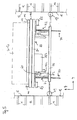
- eine perspektivische Darstellung des erfindungsgemäßen Lagerregals mit einer Transportvorrichtung;
- Fig. 2
- eine perspektivische ausschnittsweise Darstellung der Transportvorrichtung gemäß
Fig. 1 in vergrößerter Darstellung; - Fig. 3
- eine Ansicht des Lagerregals mit angedeuteter Darstellung der Behälterauflagen und der ein- und auszulagernden Behälter;
- Fig. 4
- einen Ausschnitt aus
Figur 3 in vergrößerter Darstellung; - Fig. 5
- einen Querschnitt durch die Transportvorrichtung gemäß der Linie V-V in
Fig. 2 ; - Fig. 6
- einen Längsschnitt durch die Transportvorrichtung;
- Fig. 7
- eine Ansicht von oben auf das erste Transportmittel, und
- Fig. 8
- eine Seitenansicht des ersten Transportmittels.
- Fig. 1
- a perspective view of the storage rack according to the invention with a transport device;
- Fig. 2
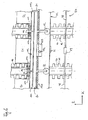
- a perspective partial view of the transport device according to
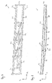
Fig. 1 in an enlarged view; - Fig. 3
- a view of the storage rack with an indication of the container supports and the storage and auszulagender container;
- Fig. 4
- a section from
FIG. 3 in an enlarged view; - Fig. 5
- a cross section through the transport device according to the line VV in
Fig. 2 ; - Fig. 6
- a longitudinal section through the transport device;
- Fig. 7
- a view from above of the first means of transport, and
- Fig. 8
- a side view of the first transport.
Um die einzulagernden Behälter 50 bis 53 in entsprechende Lagerplätze einbeziehungsweise auslagern zu können, weisen die Regaleinheiten 20, 22 Seitenwände 12 mit an senkrecht verlaufenden Ständern 14 paarweise gegenüberliegend angebrachten Behälterauflagen 16 auf (siehe
Wie aus
Zur Zustellung oder Entnahme eines Behälters 50 bis 57 ist die steuerbare Transportvorrichtung 60 so eingerichtet, dass die Behälter 50 bis 57 in einer ersten Raumrichtung Z, in einer zweiten Raumrichtung X und in einer dritten Raumrichtung Y transportierbar sind. Die drei Raumrichtung X, Y, Z stehen in vorliegendem Ausführungsbeispiel rechtwinklig zueinander. Im Folgenden wird die Raumrichtung Z auch als Vertikalrichtung, die Raumrichtung X auch als Längsrichtung und die Raumrichtung Y auch als Querrichtung bezeichnet (siehe
Um den Transport der Behälter 50 bis 57 in die Vertikal-, Längs- und Querrichtung zu ermöglichen, weist die Transportvorrichtung 60 ein erstes Transportmittel 70 und ein zweites Transportmittel 80 sowie eine Übergabevorrichtung 90 auf (siehe insbesondere
Das erste Transportmittel 70 ist nach Art einer Hubbühne aufgebaut, mittels eines Antriebes in der Vertikalrichtung Z verfahrbar und weist zwei parallel zueinander ausgerichtete Träger 71, 72 auf. Wie die
Das erste Transportmittel 70 weist zwei Vorspannelemente 77 auf, die sich an der Unterseite der Träger 71, 72 erstrecken. Jedes Vorspannelement 77 weist vier Vorspannmodule 78 in Form von Zugstangen auf. Im mittleren Bereich des Vorspannelementes 77 ist ein Spannschloss 79 zur Regulierung der durch das Vorspannelement 77 zu erzeugenden Vorspannung vorgesehen. Die Spannkraftjustierung kann aber zusätzlich oder alternativ in den Endbereichen der Endmodule des Vorspannelements 77 erfolgen. Das Vorspannelement 77 verläuft im mittleren Bereich in einem Abstand von den Trägern 71, 72. So kann infolge des sich ergebenden Hebelarms ein Drehmoment erzeugt werden, das entgegengesetzt zu dem durch das Gewicht der Transportvorrichtung 60 und die Behälter 50 bis 57 erzeugte Drehmoment wirkt. Dies führt zu einer Verringerung der Durchbiegung des Trägers 71, 72 und ermöglicht eine größere Lastaufnahme des Trägers 71, 72 im Vergleich zu einem Träger ohne Vorspannelement 77.The first transporting
Bei der Montage der Träger 71, 72 werden die einzelnen Trägermodule 73 miteinander verschraubt. An der Unterseite der Träger 71, 72 wird an den Verbindungsstellen der Trägermodule 73 jeweils ein Verbindungsarm angeordnet, an dessen Endbereich das Vorspannelement 77 beabstandet von den Trägern 71, 72 festgelegt wird. Ferner weist das erste Transportmittel 70 zwei schräg verlaufende Aussteifungselemente 75 und zwei in den Endbereichen der Träger 71, 72 vorgesehene Querträger 74 auf (siehe
Aus
Um während der Bewegung des ersten Transportmittels 70 ein Schwenken der Träger 71, 72 in Querrichtung Y zu vermeiden, sind an den Querträgern 71, 72 und den Streben 76 mehrere Räder 19 vorgesehen, die sich an den Vertikalträgern der Regaleinheiten 20, 22 abstützen.In order to avoid a pivoting of the
Wie insbesondere den
Der Zahnstangenantrieb umfasst eine aus mehreren Zahnstangenmodulen 121 gebildete Zahnstange 120, ein mit der Zahnstange 120 zusammenwirkendes Zahnrad 122 und einen Motor 123 für den Antrieb des Zahnrades 122 auf. Durch die Modulbauweise der Zahnstange 120 kann diese ebenfalls an das erste Transportmittel 70 mit unterschiedlicher Länge angepasst werden. Die Zahnstangenmodule 121 sind auf den Streben 76 des ersten Transportmittels 70 gelagert. Das Zahnrad 122 und der Motor 123 sind derart an dem Fahrgestell 81 angebracht, dass die Zähne des Zahnrades 122 mit den Zähnen der Zahnstange 120 in einen Griff gelangen können (siehe
Zur Führung des zweiten Transportmittels 80 dienen einerseits die auf einem Flansch des Trägers 71, 72 verfahrbaren Räder 82. Zusätzliche Räder 83 greifen an vertikal ausgerichteten Flanschen des Trägers 71, 72 an und dienen als seitliche Führung des Fahrgestells 81 an den Trägern 71, 72.To guide the second transport means 80 serve on the one hand on a flange of the
Die an der Transportvorrichtung 60 vorgesehene Übergabevorrichtung 90 umfasst zur Handhabung der Behälter 50 bis 57 bei der vorliegenden Ausführungsform beispielhaft vier Übergabeeinheiten 100, 102, 104 und 106. Mittels dieser vier Übergabeeinheiten 100 bis 106 wird nachfolgend entsprechend der in
Nach Einbringen der Behälter 50 bis 53 in die Bedienöffnung 30 ermittelt die Höhenmesseinrichtung 40 die Höhen aller Behälter 50 bis 53. Vorliegend haben alle vier Behälter die gleiche Höhe. Anschließend ermittelt die Steuereinheit einen Bereich in einer der Regaleinheiten 20, 22, in dem vorzugsweise vier nebeneinander liegende freie Lagerplätze vorhanden. Hier werden beispielhaft die Lagerplätze 24, 25, 26 und 27 in der Regaleinheit 22 ermittelt (siehe
Die Übergabevorrichtung 90 ist derart eingerichtet, dass jeder Übergabeeinheit 100 bis 106 jeweils ein Behälter 50 bis 53 zugeordnet werden kann. Im vorliegenden Fall weisen alle vier Übergabeeinheiten 100 bis 106 jeweils eine Tragplatte 108 auf, die jeweils auf dem Fahrgestell 81 des zweiten Transportmittels 80 abgestützt sind. Diese Tragplatten 108 sind voneinander getrennt gelagert und auch separat und unabhängig voneinander in der Horizontalrichtung X verfahrbar.The transfer device 90 is set up such that each
Bei einer anderen Variante, können die Übergabeeinheiten 100 bis 106 auf einer gemeinsamen Tragplatte gelagert und nur zusammen verfahrbar sein. Generell können mehrere Tragplatten 108 vorgesehen sein, die in Längsrichtung X oder in Querrichtung Y nebeneinander positioniert werden können und in Längsrichtung X und/oder Querrichtung Y verfahrbar sein können und zwar unabhängig voneinander oder gruppenweise. Weiterhin können beispielsweise auch zwei Übergabeeinheiten auf einer Tragplatte 108 abgestützt und zusammen verfahrbar sein. Ferner ist jede Übergabeeinheit 100 bis 106 mit einem Antrieb ausgestattet, der separat ansteuer- und bewegbar ist.In another variant, the
Wie insbesondere in den
Mit anderen Worten greifen jeweils zwei Antriebseinheiten an einem Behälters 50 bis 53 an, um diesen von der Ablagefläche der Bedienöffnung 30 auf die Tragplatte 108 der jeweiligen Übergabeeinheit 100 bis 106 zu ziehen. DieIn other words, two drive units each engage a
Übergabeeinheiten 100 bis 106 bewegen die Behälter 50 bis 53 also gleichzeitig in Querrichtung Y.
Nachdem die Behälter 50 bis 53 von der Übergabevorrichtung 90 aus der Bedienöffnung 30 aufgenommen worden sind, können die Behälter 50 bis 53 nun mittels der Transportvorrichtung 60 entlang des Transportschachtes in Längsrichtung X und Vertikalrichtung Z verfahren werden. Nach Erreichen der von der Steuereinheit zugeteilten Position schieben die Übergabeeinheiten 100 bis 106 die Behälter 50 bis 53 in die Lagerplätze 24 bis 27 (siehe
Nachdem nun die Behälter 50 bis 53 in den Lagerplätzen 24 bis 27 eingelagert worden sind, kann im direkten Anschluß die Auslagerung der Behälter 54, 55, 56, 57 erfolgen (siehe
Anschließend wird die Transportvorrichtung 60 auf Höhe der Bedienöffnung 30 verfahren, wobei das zweite Transportmittel 80 in Längsrichtung X derart positioniert wird, dass daraufhin alle vier Behälter 54 bis 57 gleichzeitig in die Bedienöffnung 30 geschoben werden können.Subsequently, the
Das Ziehen und Schieben der Behälter 54 bis 57 erfolgt gleichermaßen wie oben beim Einlagern der Behälter 50 bis 53 erläutert mit den Antriebseinheiten der Übergabeeinheiten 100 bis 106, das heisst mittels der Kettenantriebe als Greif-/Zieheinheiten.The pulling and pushing of the
Die beschriebene Ausführungsform zeichnet sich insbesondere dadurch aus, dass durch das Einlagern beziehungsweise Auslagern mehrerer Behälter 50 bis 53 beziehungsweise 54 bis 57 schnellere Zugriffszeiten, d.h. kürzere Zustell- oder Entnahmezeiten erreicht werden. Besonders bevorzugt werden die Behälter gleichzeitig der Bedienöffnung 30 zugestellt oder aus dieser zu den Lagerplätzen befördert. Weiterhin kann die Übergabevorrichtung 90 modulartig durch Hinzufügen oder Entfernen von einzelnen Übergabeeinheiten gestaltet und so an die flexibel veränderbare Kapazität des Lagerregals 10 angepasst werden. Für den Fall, dass Regaleinheiten 20, 22 hinzugefügt oder entfernt und dementsprechend das erste Transportmittel 70 modulartig mittels der Trägermodule/Transportmittelmodule 73 angepasst wird, kann in Abstimmung hierzu die Anzahl der Übergabeeinheiten variiert werden, so dass eine optimale Bedienung des Lagerregals erreicht werden kann.The embodiment described is characterized in particular by the fact that by storing or retrieving a plurality of
Im oben erläuterten Ausführungsbeispiel sind alle vier Übergabeeinheiten 100 bis 106 auf dem zweiten Transportmittel 80 abgestützt und somit gemeinsam entlang der Längsrichtung X auf dem ersten Transportmittel 70 verfahrbar. Grundsätzlich kann aber auch eine Gruppe von Übergabeeinheiten, beispielsweise zwei Übergabeeinheiten, getrennt von einer weiteren Gruppe von Übergabeeinheiten auf dem zweiten Transportmittel 80 verfahrbar gelagert sein.In the embodiment explained above, all four
In Folge der oben erläuterten Ausgestaltung der Übergabevorrichtung 90 mit den mehreren Übergabeeinheiten 100 bis 106 kann eine Gruppe von mehreren Behältern 50 bis 53, insbesondere von vier Behältern, gleichzeitig den Lagerplätzen zugestellt oder aus diesen entnommen werden. So können entweder alle vier Behälter 50 bis 53 in einer horizontalen Ebene in benachbarten Regaleinheiten eingeschoben werden. Es ist jedoch auch möglich, zunächst eine Gruppe von beispielsweise zwei Behältern in zwei benachbarte oder aber beabstandete Lagerplätze einer Ebene und in einem zweiten Schritt eine zweite Gruppe von zwei Behältern in benachbarte oder beabstandete Lagerplätze einer zweiten Ebene einzulagern.As a result of the above-described embodiment of the transfer device 90 with the plurality of
Schließlich können auch unterschiedlich hohe Behälter 50 bis 57 eingesetzt werden, da die Seitenwände 12 vorzugsweise rasterförmig gestaltet sind, und mittels der oben beschriebenen Höhenmessung die jeweils geeigneten Lagerplätze ermittelt werden können. Ferner können die Behälter 50 bis 57 ohne zusätzliche Ladungsträger befördert werden. In bevorzugter Ausgestaltung ist das gleichzeitige Ein- beziehungsweise Auslagern von vier Behältern 50 bis 53 beziehungsweise 54 bis 57 möglich. Als Behälter 50 bis 57 können übliche Kleinladungsträger, gegebenenfalls auch mit unterschiedlichen Höhen, und beispielsweise mit bis zu 50 kg Zuladung eingesetzt werFinally, it is also possible to use
- 1010
- Lagerregalstorage rack
- 1212
- SeitenwandSide wall
- 1414
- Ständerstand
- 1616
- Behälterauflagecontainer support
- 1717
- Nutgroove
- 1818
- Stirnflächeface
- 1919
- Radwheel
- 2020
- Regaleinheitshelving unit
- 2222
- Regaleinheitshelving unit
- 2424
- Lagerplatzcampsite
- 2525
- Lagerplatzcampsite
- 2626
- Lagerplatzcampsite
- 2727
- Lagerplatzcampsite
- 3030
- Bedienöffnungoperating opening
- 4040
- HöhenmesseinrichtungHeight measuring device
- 4242
- Lichtschrankephotocell
- 5050
- Behältercontainer
- 5151
- Behältercontainer
- 5252
- Behältercontainer
- 5353
- Behältercontainer
- 5454
- Behältercontainer
- 5555
- Behältercontainer
- 5656
- Behältercontainer
- 5757
- Behältercontainer
- 5858
- Auflagestegsupport web
- 5959
- Seitenflächeside surface
- 6060
- Transportvorrichtungtransport device
- 7070
- erstes Transportmittelfirst means of transport
- 7171
- Trägercarrier
- 7272
- Trägercarrier
- 7373
- Trägermodulcarrier module
- 7474
- Querträgercrossbeam
- 7575
- Aussteifungselementstiffening
- 7676
- Strebestrut
- 7777
- Vorspannelementbiasing member
- 7878
- Vorspannmodulbiasing module
- 7979
- Spannschlossturnbuckle
- 8080
- zweites Transportmittelsecond means of transport
- 8181
- Fahrgestellchassis
- 8282
- Radwheel
- 8383
- Radwheel
- 9090
- ÜbergabevorrichtungTransfer device
- 100100
- ÜbergabeeinheitTransfer unit
- 102102
- ÜbergabeeinheitTransfer unit
- 104104
- ÜbergabeeinheitTransfer unit
- 106106
- ÜbergabeeinheitTransfer unit
- 108108
- Tragplattesupport plate
- 110110
- KetteChain
- 112112
- Antriebswelledrive shaft
- 114114
- KetteChain
- 116116
- Antriebswelledrive shaft
- 117117
- Mitnehmertakeaway
- 120120
- Zahnstangerack
- 121121
- ZahnstangenmodulRack module
- 122122
- Zahnradgear
- 123123
- Motorengine
- XX
- erste Horizontalrichtung/Längsrichtungfirst horizontal direction / longitudinal direction
- YY
- zweite Horizontalrichtung/Querrichtungsecond horizontal direction / transverse direction
- ZZ
- Vertikalrichtungvertical direction
Claims (13)
- Storage rack (10) having a plurality of rack units (20, 22) with container supports (16) spaced one above the other, said supports being disposed in pairs on opposite side walls (12) of the rack units (20, 22) to form storage locations for containers (50 to 53),
wherein the containers (50 to 53) can be placed in or removed from the storage locations by means of a controllable transport device (60),
wherein the transport device (60) has at least one first transport means (70) and one second transport means (80), wherein the first transport means (70) is able to move in the vertical direction (Z), and
the second transport means (80) is supported on the first transport means (70) and is able to move in a first horizontal direction (X) relative to the first transport means (70),
wherein a transfer device (90) for handling a number of containers (50 to 53) is provided,
wherein the transfer device (90) is arranged on the second transport means (80) and comprises a number of transfer units (100, 102, 104, 106) for placing the containers (50 to 53) into and removing them from stock,
wherein each transfer unit (100, 102, 104, 106) can be associated with one container (50 to 53) and each transfer unit (100, 102, 104, 106) can be controlled and moved separately and
wherein the transfer unit (100, 102, 104, 106) is configured and arranged in such a way to be able to move each container (50 to 53) in a second horizontal direction (Y) which is essentially perpendicular to the first horizontal direction (X),
wherein at least one operating hatch (30) for submitting and retrieving the containers (50 to 53) is provided, wherein the operating hatch (30) is dimensioned in such a way that all the containers (50 to 53) can be placed into and/or removed from stock simultaneously. - Storage rack according to claim 1, characterised in that the transfer device is made up of a number of modular transfer units (100, 102, 104, 106) which can be joined to each other detachably wherein the number of transfer units is variable depending on the number of storage units.
- Storage rack according to claim 1 or 2, characterised in that the first transport means (70) is made up of a number of transport-means modules joined to each other detachably and the number of said modules is variable depending on the number of storage units.
- Storage rack according to one of the claims 1 to 3, characterised in that the number of transfer units is variable depending on the number of storage units and/or depending on the number of transport-means modules.
- Storage rack according to one of the claims 1 to 4, characterised in that the transfer units (100, 102, 104, 106) are configured as gripping units and/or pulling units.
- Storage rack according to one of the claims 1 to 5, characterised in that the transfer units (100, 102, 104, 106) are arranged to be able to place the containers (50 to 53) into stock or to remove them at least in groups synchronously or successively.
- Storage rack according to one of the claims 1 to 6, characterised in that four transfer units (100, 102, 104, 106) are provided which are preferably configured as gripping units.
- Storage rack according to one of the claims 1 to 7, characterised in that in the vicinity of the operating hatch (30) there is a height-measuring device (40) for measuring the height of the containers (50 to 53).
- Storage rack according to one of the claims 1 to 8, characterised in that a shutter device is provided in the area of the operating hatch (30) for opening and closing the operating hatch (30), in particular a high-speed door.
- Storage rack according to one of the claims 1 to 9, characterised in that the container supports (16) are provided in a grid-like array on the side walls (12).
- Storage rack according to one of the claims 1 to 10, characterised in that the container supports (16) are pressed in a meandering shape into the side walls (12).
- Storage rack according to one of the claims 1 to 11, characterised in that the container supports (16) have grooves (17) into and out of which the support bars (58) of the containers (50 to 53) can be guided.
- Storage rack according to one of the claims 1 to 12, characterised in that the first transport means (70), the second transport means (80) and/or the transfer units (100, 102, 104, 106) can be moved by means of a rack and pinion drive and/or a chain drive.
Priority Applications (1)
| Application Number | Priority Date | Filing Date | Title |
|---|---|---|---|
| PL08803332T PL2185447T5 (en) | 2007-08-29 | 2008-08-28 | Storage shelf having transport device |
Applications Claiming Priority (2)
| Application Number | Priority Date | Filing Date | Title |
|---|---|---|---|
| DE102007040863A DE102007040863B4 (en) | 2007-08-29 | 2007-08-29 | Storage rack with transport device |
| PCT/EP2008/061320 WO2009027479A1 (en) | 2007-08-29 | 2008-08-28 | Storage shelf having transport device |
Publications (3)
| Publication Number | Publication Date |
|---|---|
| EP2185447A1 EP2185447A1 (en) | 2010-05-19 |
| EP2185447B1 EP2185447B1 (en) | 2013-03-13 |
| EP2185447B2 true EP2185447B2 (en) | 2016-10-19 |
Family
ID=39927921
Family Applications (1)
| Application Number | Title | Priority Date | Filing Date |
|---|---|---|---|
| EP08803332.9A Active EP2185447B2 (en) | 2007-08-29 | 2008-08-28 | Storage shelf having transport device |
Country Status (11)
| Country | Link |
|---|---|
| US (1) | US8920098B2 (en) |
| EP (1) | EP2185447B2 (en) |
| JP (1) | JP5713675B2 (en) |
| KR (1) | KR20100046220A (en) |
| CN (1) | CN101784465B (en) |
| CA (1) | CA2695502C (en) |
| DE (1) | DE102007040863B4 (en) |
| DK (1) | DK2185447T4 (en) |
| ES (1) | ES2407085T5 (en) |
| PL (1) | PL2185447T5 (en) |
| WO (1) | WO2009027479A1 (en) |
Families Citing this family (20)
| Publication number | Priority date | Publication date | Assignee | Title |
|---|---|---|---|---|
| DE202009019202U1 (en) * | 2009-07-13 | 2019-01-25 | Bellheimer Metallwerk Gmbh | hybrid bearings |
| DE102010035231B4 (en) * | 2010-08-24 | 2013-05-16 | Hänel & Co. | Storage rack system for storage of stored goods |
| EP2508163B1 (en) * | 2011-04-05 | 2013-11-20 | Hänel & Co. | Automated storage rack and storage product carrier with access control |
| EP2726385B1 (en) | 2011-07-01 | 2016-04-06 | Effimat Storage Technology ApS | A vertical lift storage system, a method of operating such a system and a computer and computer readable medium for carring out such a method |
| NL2009632C2 (en) * | 2012-03-30 | 2013-10-01 | Visser S Gravendeel Holding | SYSTEM FOR STORAGE AND / OR ISSUE OF PRODUCTS AND / OR PACKAGING. |
| CN102862772B (en) * | 2012-09-19 | 2015-04-15 | 深圳市华星光电技术有限公司 | Loading device and storage device of LCD (liquid crystal display) cassette |
| EP2881905B1 (en) | 2013-12-09 | 2018-02-07 | Cleveron AS | Self-service parcel terminal |
| CN105672230B (en) * | 2016-01-08 | 2017-10-31 | 苏交科集团股份有限公司 | Marine precast splice type bunker and building method |
| CN106276291A (en) * | 2016-10-13 | 2017-01-04 | 广州双拥智能科技有限公司 | Barrel buffer |
| JP6766584B2 (en) * | 2016-10-19 | 2020-10-14 | 株式会社ダイフク | Goods transport equipment |
| CN107380874A (en) * | 2017-06-29 | 2017-11-24 | 傅峰峰 | A kind of locker |
| CA3070772A1 (en) * | 2017-07-21 | 2019-01-24 | Sentien Robotics, Inc. | Uav retrieval and deployment system |
| FR3073831B1 (en) | 2017-11-23 | 2021-04-30 | Savoye | AUTOMATIC SETPOINT DEVICE WITH AT LEAST ONE LOADING / TAKING-UP BUFFER ZONE, AND CORRESPONDING PROCESS FOR HANDLING LOADS. |
| DE102017129120B4 (en) * | 2017-12-07 | 2021-01-21 | Rainer Buchmann | Modular storage and picking facility |
| US20200017299A1 (en) | 2018-07-12 | 2020-01-16 | Walmart Apollo, Llc | Automated storage retrieval system connection and communication protocol |
| WO2020014615A1 (en) | 2018-07-12 | 2020-01-16 | Walmart Apollo, Llc | System and method for product recognition and assignment at an automated storage and retrieval device |
| US11138544B2 (en) | 2018-08-24 | 2021-10-05 | Cleveron As | Method and a device for fast entry and storage of parcels |
| FR3088182A1 (en) * | 2018-11-09 | 2020-05-15 | Iad Mecatronique | AUTOMATED STORAGE FURNITURE |
| CN111591641B (en) * | 2019-02-21 | 2022-04-22 | 江苏华章物流科技股份有限公司 | Automatic three-dimensional container system and storing and taking method thereof |
| EP4199790A4 (en) * | 2021-04-07 | 2023-11-01 | Ücge Magaza Ekipmanlari Pazarlama Sanayi Ve Ticaret Anonim Sirketi | Product shelf filling system |
Citations (1)
| Publication number | Priority date | Publication date | Assignee | Title |
|---|---|---|---|---|
| DE29821103U1 (en) † | 1998-11-25 | 1999-02-18 | Remmert Friedrich Gmbh | General cargo storage |
Family Cites Families (35)
| Publication number | Priority date | Publication date | Assignee | Title |
|---|---|---|---|---|
| US3746189A (en) * | 1966-04-18 | 1973-07-17 | Clark Equipment Co | Automatic control system for storage systems transfer cart |
| US3492704A (en) * | 1967-06-15 | 1970-02-03 | Donald D Schwellenbach | Apparatus for making concrete blocks |
| US3792758A (en) * | 1971-11-15 | 1974-02-19 | American Chain & Cable Co | Stacker crane construction |
| US4724640A (en) * | 1984-03-02 | 1988-02-16 | Fred Patane | Storage facility |
| JPH02158501A (en) * | 1988-12-08 | 1990-06-19 | Toshiba Corp | Automatic housing warehouse |
| US5043962A (en) * | 1989-03-21 | 1991-08-27 | Hewlett-Packard Company | Cartridge handling system |
| US5104277A (en) * | 1989-04-06 | 1992-04-14 | Hewlett-Packard Company | Method and apparatus for automatically changing printed circuit board test fixtures |
| US5094584A (en) * | 1989-04-06 | 1992-03-10 | Hewlett-Packard Company | Method and apparatus for automatically changing printed circuit board test fixtures |
| IT1237950B (en) * | 1990-01-15 | 1993-06-19 | Fata Automation | ADAPTABLE AUTOMATIC WAREHOUSE |
| DE4220116C2 (en) * | 1991-10-25 | 2003-07-17 | Ssi Schaefer Noell Gmbh | Load suspension device for a storage and retrieval machine |
| FR2686327B1 (en) * | 1992-01-22 | 1994-04-29 | Technicatome | ROBOTIC STORAGE SYSTEM FOR SAME, IDENTIFIABLE AND INDIVIDUALLY SELECTABLE OBJECTS. |
| DE4202801C2 (en) | 1992-01-31 | 1995-09-14 | Accumulata Verwaltungs Gmbh | Sales facility |
| DE4416103C2 (en) * | 1994-04-19 | 1999-01-07 | Bellheimer Metallwerk Gmbh | high level rack |
| JPH0885603A (en) * | 1994-09-16 | 1996-04-02 | Daifuku Co Ltd | Storage device |
| DE19513179C2 (en) | 1995-03-31 | 1997-02-13 | Bellheimer Metallwerk Gmbh | Storage rack |
| JP3174014B2 (en) * | 1997-05-20 | 2001-06-11 | 都市改造システム株式会社 | Three-dimensional bicycle parking lot |
| DE19805420C2 (en) * | 1998-02-11 | 2000-02-17 | Heinz Rathmer | Presentation facility |
| SE9800613D0 (en) | 1998-02-27 | 1998-02-27 | Mats Arneving | Storage device |
| DE19811034A1 (en) * | 1998-03-13 | 1999-09-16 | Grau Software Gmbh | Data storage device |
| US6386116B1 (en) * | 2000-06-23 | 2002-05-14 | Storage Technology Corporation | Propulsion decoupling method and system for multiple track mounted robots of an automated storage library |
| JP4727069B2 (en) | 2001-05-31 | 2011-07-20 | 株式会社イトーキ | Automatic warehouse and transfer equipment |
| JP4815067B2 (en) | 2001-05-31 | 2011-11-16 | 株式会社イトーキ | Automatic warehouse |
| US6923612B2 (en) * | 2002-03-29 | 2005-08-02 | TGW Transportgeräte GmbH & Co. KG | Load-handling system and telescopic arm therefor |
| JP2004083250A (en) * | 2002-08-28 | 2004-03-18 | Nippon Yusoki Co Ltd | Bucket and carrying-in/shipping method for bucket |
| DE20305123U1 (en) * | 2003-03-29 | 2004-04-29 | Megamat GmbH Büro + Lagertechnik | Drive device for a storage device |
| US7931431B2 (en) * | 2003-05-06 | 2011-04-26 | Bec Companies, Inc. | Automated material handling system with load transfer vehicles |
| US7387485B2 (en) * | 2003-09-29 | 2008-06-17 | Quantum Corporation | Cartridge transport assembly |
| AT500229B1 (en) * | 2004-03-15 | 2008-12-15 | Tgw Mechanics Gmbh | COMPUTER-CONTROLLED TRANSPORT DEVICE |
| DE102004042061B4 (en) | 2004-08-26 | 2008-08-14 | Hänel GmbH & Co KG | storage rack |
| JP4387283B2 (en) * | 2004-10-25 | 2009-12-16 | 富士通株式会社 | Storage shelf transport mechanism, control method therefor, and control program therefor |
| JP4666213B2 (en) | 2005-07-05 | 2011-04-06 | 株式会社ダイフク | Goods storage equipment |
| DE202005017269U1 (en) | 2005-10-10 | 2006-01-05 | Hänel & Co. | Storage racking has first transporting means which consists of several detachably interconnected modules, the number of which is variable in dependence upon number of rack units |
| DE102005048379B4 (en) * | 2005-10-10 | 2009-08-20 | Hänel & Co. | Storage rack with a variety of shelving units |
| US7686560B2 (en) * | 2005-12-08 | 2010-03-30 | Conestoga Cold Storage | Rack, conveyor and shuttle automated pick system |
| DE202007003084U1 (en) | 2007-03-02 | 2007-05-10 | Hänel & Co. | Load carrier for storage rack, has superimposed and uniformly spaced carrier support whereby load carrier is made of plastic and boundary wall projects support |
-
2007
- 2007-08-29 DE DE102007040863A patent/DE102007040863B4/en active Active
-
2008
- 2008-08-28 WO PCT/EP2008/061320 patent/WO2009027479A1/en active Application Filing
- 2008-08-28 JP JP2010522375A patent/JP5713675B2/en not_active Expired - Fee Related
- 2008-08-28 DK DK08803332.9T patent/DK2185447T4/en active
- 2008-08-28 US US12/675,328 patent/US8920098B2/en active Active
- 2008-08-28 CN CN200880104417.5A patent/CN101784465B/en active Active
- 2008-08-28 PL PL08803332T patent/PL2185447T5/en unknown
- 2008-08-28 CA CA2695502A patent/CA2695502C/en not_active Expired - Fee Related
- 2008-08-28 EP EP08803332.9A patent/EP2185447B2/en active Active
- 2008-08-28 ES ES08803332.9T patent/ES2407085T5/en active Active
- 2008-08-28 KR KR1020107004061A patent/KR20100046220A/en not_active Application Discontinuation
Patent Citations (1)
| Publication number | Priority date | Publication date | Assignee | Title |
|---|---|---|---|---|
| DE29821103U1 (en) † | 1998-11-25 | 1999-02-18 | Remmert Friedrich Gmbh | General cargo storage |
Also Published As
| Publication number | Publication date |
|---|---|
| EP2185447A1 (en) | 2010-05-19 |
| PL2185447T5 (en) | 2017-09-29 |
| EP2185447B1 (en) | 2013-03-13 |
| CN101784465B (en) | 2015-05-13 |
| CA2695502C (en) | 2016-03-15 |
| CA2695502A1 (en) | 2009-03-05 |
| DK2185447T4 (en) | 2017-01-23 |
| DE102007040863A1 (en) | 2009-03-05 |
| JP5713675B2 (en) | 2015-05-07 |
| CN101784465A (en) | 2010-07-21 |
| KR20100046220A (en) | 2010-05-06 |
| ES2407085T5 (en) | 2017-04-25 |
| DK2185447T3 (en) | 2013-04-02 |
| WO2009027479A1 (en) | 2009-03-05 |
| US20100307989A1 (en) | 2010-12-09 |
| US8920098B2 (en) | 2014-12-30 |
| PL2185447T3 (en) | 2013-08-30 |
| ES2407085T3 (en) | 2013-06-11 |
| JP2010536687A (en) | 2010-12-02 |
| DE102007040863B4 (en) | 2010-07-29 |
Similar Documents
| Publication | Publication Date | Title |
|---|---|---|
| EP2185447B2 (en) | Storage shelf having transport device | |
| EP1934120B1 (en) | Storage rack with a multiplicity of rack units | |
| EP2609021B1 (en) | Storage shelf system for storing storage goods | |
| DE102007017365B4 (en) | Method for storing stored goods in a storage rack with several rack units and a transport shaft and such a storage rack | |
| DE202016009161U1 (en) | storage system | |
| EP3475212B1 (en) | High-bay warehouse with storage-and-retrieval units provided therein for storing and retrieving, or transferring, articles | |
| DE19513179C2 (en) | Storage rack | |
| DE202005017269U1 (en) | Storage racking has first transporting means which consists of several detachably interconnected modules, the number of which is variable in dependence upon number of rack units | |
| WO2014072265A1 (en) | Stored goods extractor for an automatic storage system | |
| EP2746193B1 (en) | Vehicle for a warehouse, stacker crane, warehouse and corresponding method | |
| DE102019129124A1 (en) | Flexible picking storage system for containers of different dimensions | |
| EP3976513A1 (en) | Transfer station for loading goods pallets in a logistics system and logistics system | |
| EP1140671A1 (en) | Method for storing warehouse goods and/or removing the same from storage, warehousing device and warehouse goods carrier | |
| EP2138427B1 (en) | Load bearer for loading and unloading loads into or out of storage areas of a shelf assembly | |
| EP0609757A2 (en) | Channel shelf for stocking and destocking case- or platelike goods, especially stacks of corrugated cardboards of any dimension | |
| EP0798238B1 (en) | Storage system for pallets for long articles | |
| EP1231164A1 (en) | Shelf storage | |
| EP0634334B1 (en) | Storage container with guiding elements | |
| DE19724378A1 (en) | Shelf with unloading device | |
| DE19920923B4 (en) | Storage system, especially for high-bay warehouses | |
| EP1862405B1 (en) | Method for gripping piece goods using gripper devices of an input and output system and device therefor | |
| WO2005097631A1 (en) | Shelf warehouse and vertical transport device | |
| DE10349469A1 (en) | Goods and workpieces handling system for use in warehouse has modular flat rectangular pallets which may be fastened together to assemble large pallets movable on rollers | |
| DE102014206590A1 (en) | Logistics system and method for transferring and / or taking over goods between a vehicle and a warehouse | |
| DE102012112828A1 (en) | Storage and retrieval unit for storing and removing articles into and from shelf, has chassis whose width is transverse to first axis and second axis, and guide assembly is located eccentrically to center of chassis |
Legal Events
| Date | Code | Title | Description |
|---|---|---|---|
| PUAI | Public reference made under article 153(3) epc to a published international application that has entered the european phase |
Free format text: ORIGINAL CODE: 0009012 |
|
| 17P | Request for examination filed |
Effective date: 20100301 |
|
| AK | Designated contracting states |
Kind code of ref document: A1 Designated state(s): AT BE BG CH CY CZ DE DK EE ES FI FR GB GR HR HU IE IS IT LI LT LU LV MC MT NL NO PL PT RO SE SI SK TR |
|
| AX | Request for extension of the european patent |
Extension state: AL BA MK RS |
|
| DAX | Request for extension of the european patent (deleted) | ||
| 17Q | First examination report despatched |
Effective date: 20120307 |
|
| GRAP | Despatch of communication of intention to grant a patent |
Free format text: ORIGINAL CODE: EPIDOSNIGR1 |
|
| GRAS | Grant fee paid |
Free format text: ORIGINAL CODE: EPIDOSNIGR3 |
|
| GRAA | (expected) grant |
Free format text: ORIGINAL CODE: 0009210 |
|
| AK | Designated contracting states |
Kind code of ref document: B1 Designated state(s): AT BE BG CH CY CZ DE DK EE ES FI FR GB GR HR HU IE IS IT LI LT LU LV MC MT NL NO PL PT RO SE SI SK TR |
|
| REG | Reference to a national code |
Ref country code: GB Ref legal event code: FG4D Free format text: NOT ENGLISH |
|
| REG | Reference to a national code |
Ref country code: AT Ref legal event code: REF Ref document number: 600673 Country of ref document: AT Kind code of ref document: T Effective date: 20130315 Ref country code: CH Ref legal event code: EP |
|
| REG | Reference to a national code |
Ref country code: SE Ref legal event code: TRGR |
|
| REG | Reference to a national code |
Ref country code: CH Ref legal event code: NV Representative=s name: BOHEST AG, CH |
|
| REG | Reference to a national code |
Ref country code: DK Ref legal event code: T3 |
|
| REG | Reference to a national code |
Ref country code: IE Ref legal event code: FG4D Free format text: LANGUAGE OF EP DOCUMENT: GERMAN |
|
| REG | Reference to a national code |
Ref country code: DE Ref legal event code: R096 Ref document number: 502008009493 Country of ref document: DE Effective date: 20130508 |
|
| REG | Reference to a national code |
Ref country code: ES Ref legal event code: FG2A Ref document number: 2407085 Country of ref document: ES Kind code of ref document: T3 Effective date: 20130611 |
|
| REG | Reference to a national code |
Ref country code: NL Ref legal event code: T3 |
|
| PG25 | Lapsed in a contracting state [announced via postgrant information from national office to epo] |
Ref country code: LT Free format text: LAPSE BECAUSE OF FAILURE TO SUBMIT A TRANSLATION OF THE DESCRIPTION OR TO PAY THE FEE WITHIN THE PRESCRIBED TIME-LIMIT Effective date: 20130313 Ref country code: BG Free format text: LAPSE BECAUSE OF FAILURE TO SUBMIT A TRANSLATION OF THE DESCRIPTION OR TO PAY THE FEE WITHIN THE PRESCRIBED TIME-LIMIT Effective date: 20130613 Ref country code: NO Free format text: LAPSE BECAUSE OF FAILURE TO SUBMIT A TRANSLATION OF THE DESCRIPTION OR TO PAY THE FEE WITHIN THE PRESCRIBED TIME-LIMIT Effective date: 20130613 |
|
| REG | Reference to a national code |
Ref country code: LT Ref legal event code: MG4D |
|
| PG25 | Lapsed in a contracting state [announced via postgrant information from national office to epo] |
Ref country code: GR Free format text: LAPSE BECAUSE OF FAILURE TO SUBMIT A TRANSLATION OF THE DESCRIPTION OR TO PAY THE FEE WITHIN THE PRESCRIBED TIME-LIMIT Effective date: 20130614 Ref country code: SI Free format text: LAPSE BECAUSE OF FAILURE TO SUBMIT A TRANSLATION OF THE DESCRIPTION OR TO PAY THE FEE WITHIN THE PRESCRIBED TIME-LIMIT Effective date: 20130313 Ref country code: LV Free format text: LAPSE BECAUSE OF FAILURE TO SUBMIT A TRANSLATION OF THE DESCRIPTION OR TO PAY THE FEE WITHIN THE PRESCRIBED TIME-LIMIT Effective date: 20130313 |
|
| REG | Reference to a national code |
Ref country code: PL Ref legal event code: T3 |
|
| REG | Reference to a national code |
Ref country code: SK Ref legal event code: T3 Ref document number: E 14327 Country of ref document: SK |
|
| PG25 | Lapsed in a contracting state [announced via postgrant information from national office to epo] |
Ref country code: HR Free format text: LAPSE BECAUSE OF FAILURE TO SUBMIT A TRANSLATION OF THE DESCRIPTION OR TO PAY THE FEE WITHIN THE PRESCRIBED TIME-LIMIT Effective date: 20130313 |
|
| PG25 | Lapsed in a contracting state [announced via postgrant information from national office to epo] |
Ref country code: IS Free format text: LAPSE BECAUSE OF FAILURE TO SUBMIT A TRANSLATION OF THE DESCRIPTION OR TO PAY THE FEE WITHIN THE PRESCRIBED TIME-LIMIT Effective date: 20130713 Ref country code: RO Free format text: LAPSE BECAUSE OF FAILURE TO SUBMIT A TRANSLATION OF THE DESCRIPTION OR TO PAY THE FEE WITHIN THE PRESCRIBED TIME-LIMIT Effective date: 20130313 Ref country code: PT Free format text: LAPSE BECAUSE OF FAILURE TO SUBMIT A TRANSLATION OF THE DESCRIPTION OR TO PAY THE FEE WITHIN THE PRESCRIBED TIME-LIMIT Effective date: 20130715 Ref country code: EE Free format text: LAPSE BECAUSE OF FAILURE TO SUBMIT A TRANSLATION OF THE DESCRIPTION OR TO PAY THE FEE WITHIN THE PRESCRIBED TIME-LIMIT Effective date: 20130313 |
|
| REG | Reference to a national code |
Ref country code: HU Ref legal event code: AG4A Ref document number: E017525 Country of ref document: HU |
|
| PG25 | Lapsed in a contracting state [announced via postgrant information from national office to epo] |
Ref country code: CY Free format text: LAPSE BECAUSE OF FAILURE TO SUBMIT A TRANSLATION OF THE DESCRIPTION OR TO PAY THE FEE WITHIN THE PRESCRIBED TIME-LIMIT Effective date: 20130313 |
|
| PLBI | Opposition filed |
Free format text: ORIGINAL CODE: 0009260 |
|
| 26 | Opposition filed |
Opponent name: TGW LOGISTICS GROUP GMBH Effective date: 20131211 |
|
| PLAX | Notice of opposition and request to file observation + time limit sent |
Free format text: ORIGINAL CODE: EPIDOSNOBS2 |
|
| REG | Reference to a national code |
Ref country code: DE Ref legal event code: R026 Ref document number: 502008009493 Country of ref document: DE Effective date: 20131211 |
|
| PG25 | Lapsed in a contracting state [announced via postgrant information from national office to epo] |
Ref country code: MC Free format text: LAPSE BECAUSE OF FAILURE TO SUBMIT A TRANSLATION OF THE DESCRIPTION OR TO PAY THE FEE WITHIN THE PRESCRIBED TIME-LIMIT Effective date: 20130313 |
|
| PLAF | Information modified related to communication of a notice of opposition and request to file observations + time limit |
Free format text: ORIGINAL CODE: EPIDOSCOBS2 |
|
| PLBB | Reply of patent proprietor to notice(s) of opposition received |
Free format text: ORIGINAL CODE: EPIDOSNOBS3 |
|
| REG | Reference to a national code |
Ref country code: CH Ref legal event code: PCAR Free format text: NEW ADDRESS: HOLBEINSTRASSE 36-38, 4051 BASEL (CH) |
|
| PG25 | Lapsed in a contracting state [announced via postgrant information from national office to epo] |
Ref country code: MT Free format text: LAPSE BECAUSE OF FAILURE TO SUBMIT A TRANSLATION OF THE DESCRIPTION OR TO PAY THE FEE WITHIN THE PRESCRIBED TIME-LIMIT Effective date: 20130313 |
|
| PG25 | Lapsed in a contracting state [announced via postgrant information from national office to epo] |
Ref country code: LU Free format text: LAPSE BECAUSE OF NON-PAYMENT OF DUE FEES Effective date: 20130828 |
|
| REG | Reference to a national code |
Ref country code: FR Ref legal event code: PLFP Year of fee payment: 9 |
|
| PUAH | Patent maintained in amended form |
Free format text: ORIGINAL CODE: 0009272 |
|
| STAA | Information on the status of an ep patent application or granted ep patent |
Free format text: STATUS: PATENT MAINTAINED AS AMENDED |
|
| 27A | Patent maintained in amended form |
Effective date: 20161019 |
|
| AK | Designated contracting states |
Kind code of ref document: B2 Designated state(s): AT BE BG CH CY CZ DE DK EE ES FI FR GB GR HR HU IE IS IT LI LT LU LV MC MT NL NO PL PT RO SE SI SK TR |
|
| REG | Reference to a national code |
Ref country code: DE Ref legal event code: R102 Ref document number: 502008009493 Country of ref document: DE |
|
| REG | Reference to a national code |
Ref country code: CH Ref legal event code: AELC |
|
| REG | Reference to a national code |
Ref country code: NL Ref legal event code: FP |
|
| REG | Reference to a national code |
Ref country code: DK Ref legal event code: T4 Effective date: 20170119 |
|
| REG | Reference to a national code |
Ref country code: SK Ref legal event code: T5 Ref document number: E 14327 Country of ref document: SK |
|
| REG | Reference to a national code |
Ref country code: SE Ref legal event code: RPEO |
|
| PG25 | Lapsed in a contracting state [announced via postgrant information from national office to epo] |
Ref country code: LV Free format text: LAPSE BECAUSE OF FAILURE TO SUBMIT A TRANSLATION OF THE DESCRIPTION OR TO PAY THE FEE WITHIN THE PRESCRIBED TIME-LIMIT Effective date: 20161019 |
|
| REG | Reference to a national code |
Ref country code: ES Ref legal event code: DC2A Ref document number: 2407085 Country of ref document: ES Kind code of ref document: T5 Effective date: 20170425 |
|
| REG | Reference to a national code |
Ref country code: FR Ref legal event code: PLFP Year of fee payment: 10 |
|
| REG | Reference to a national code |
Ref country code: FR Ref legal event code: PLFP Year of fee payment: 11 |
|
| PGFP | Annual fee paid to national office [announced via postgrant information from national office to epo] |
Ref country code: IE Payment date: 20180823 Year of fee payment: 11 |
|
| PGFP | Annual fee paid to national office [announced via postgrant information from national office to epo] |
Ref country code: BE Payment date: 20180827 Year of fee payment: 11 Ref country code: DK Payment date: 20180827 Year of fee payment: 11 Ref country code: HU Payment date: 20180815 Year of fee payment: 11 Ref country code: CZ Payment date: 20180816 Year of fee payment: 11 Ref country code: FI Payment date: 20180821 Year of fee payment: 11 Ref country code: SK Payment date: 20180815 Year of fee payment: 11 Ref country code: TR Payment date: 20180814 Year of fee payment: 11 |
|
| REG | Reference to a national code |
Ref country code: FI Ref legal event code: MAE |
|
| REG | Reference to a national code |
Ref country code: DK Ref legal event code: EBP Effective date: 20190831 |
|
| REG | Reference to a national code |
Ref country code: AT Ref legal event code: MM01 Ref document number: 600673 Country of ref document: AT Kind code of ref document: T Effective date: 20190828 |
|
| REG | Reference to a national code |
Ref country code: SE Ref legal event code: EUG |
|
| PG25 | Lapsed in a contracting state [announced via postgrant information from national office to epo] |
Ref country code: AT Free format text: LAPSE BECAUSE OF NON-PAYMENT OF DUE FEES Effective date: 20190828 Ref country code: SE Free format text: LAPSE BECAUSE OF NON-PAYMENT OF DUE FEES Effective date: 20190829 Ref country code: FI Free format text: LAPSE BECAUSE OF NON-PAYMENT OF DUE FEES Effective date: 20190828 Ref country code: HU Free format text: LAPSE BECAUSE OF NON-PAYMENT OF DUE FEES Effective date: 20190829 |
|
| REG | Reference to a national code |
Ref country code: SK Ref legal event code: MM4A Ref document number: E 14327 Country of ref document: SK Effective date: 20190828 |
|
| PG25 | Lapsed in a contracting state [announced via postgrant information from national office to epo] |
Ref country code: CZ Free format text: LAPSE BECAUSE OF NON-PAYMENT OF DUE FEES Effective date: 20190828 Ref country code: SK Free format text: LAPSE BECAUSE OF NON-PAYMENT OF DUE FEES Effective date: 20190828 |
|
| REG | Reference to a national code |
Ref country code: BE Ref legal event code: MM Effective date: 20190831 |
|
| PG25 | Lapsed in a contracting state [announced via postgrant information from national office to epo] |
Ref country code: DK Free format text: LAPSE BECAUSE OF NON-PAYMENT OF DUE FEES Effective date: 20190831 Ref country code: IE Free format text: LAPSE BECAUSE OF NON-PAYMENT OF DUE FEES Effective date: 20190828 |
|
| PG25 | Lapsed in a contracting state [announced via postgrant information from national office to epo] |
Ref country code: BE Free format text: LAPSE BECAUSE OF NON-PAYMENT OF DUE FEES Effective date: 20190831 |
|
| REG | Reference to a national code |
Ref country code: ES Ref legal event code: FD2A Effective date: 20210108 |
|
| PG25 | Lapsed in a contracting state [announced via postgrant information from national office to epo] |
Ref country code: ES Free format text: LAPSE BECAUSE OF NON-PAYMENT OF DUE FEES Effective date: 20190829 |
|
| PGFP | Annual fee paid to national office [announced via postgrant information from national office to epo] |
Ref country code: NL Payment date: 20210823 Year of fee payment: 14 |
|
| PGFP | Annual fee paid to national office [announced via postgrant information from national office to epo] |
Ref country code: GB Payment date: 20210824 Year of fee payment: 14 |
|
| PG25 | Lapsed in a contracting state [announced via postgrant information from national office to epo] |
Ref country code: TR Free format text: LAPSE BECAUSE OF NON-PAYMENT OF DUE FEES Effective date: 20190828 |
|
| REG | Reference to a national code |
Ref country code: NL Ref legal event code: MM Effective date: 20220901 |
|
| GBPC | Gb: european patent ceased through non-payment of renewal fee |
Effective date: 20220828 |
|
| PG25 | Lapsed in a contracting state [announced via postgrant information from national office to epo] |
Ref country code: NL Free format text: LAPSE BECAUSE OF NON-PAYMENT OF DUE FEES Effective date: 20220901 |
|
| P01 | Opt-out of the competence of the unified patent court (upc) registered |
Effective date: 20230621 |
|
| PG25 | Lapsed in a contracting state [announced via postgrant information from national office to epo] |
Ref country code: GB Free format text: LAPSE BECAUSE OF NON-PAYMENT OF DUE FEES Effective date: 20220828 |
|
| PGFP | Annual fee paid to national office [announced via postgrant information from national office to epo] |
Ref country code: IT Payment date: 20230831 Year of fee payment: 16 Ref country code: CH Payment date: 20230902 Year of fee payment: 16 |
|
| PGFP | Annual fee paid to national office [announced via postgrant information from national office to epo] |
Ref country code: PL Payment date: 20230821 Year of fee payment: 16 Ref country code: FR Payment date: 20230821 Year of fee payment: 16 Ref country code: DE Payment date: 20230913 Year of fee payment: 16 |