EP2185384B1 - Puffer für automobile - Google Patents
Puffer für automobile Download PDFInfo
- Publication number
- EP2185384B1 EP2185384B1 EP08836278A EP08836278A EP2185384B1 EP 2185384 B1 EP2185384 B1 EP 2185384B1 EP 08836278 A EP08836278 A EP 08836278A EP 08836278 A EP08836278 A EP 08836278A EP 2185384 B1 EP2185384 B1 EP 2185384B1
- Authority
- EP
- European Patent Office
- Prior art keywords
- motor vehicle
- plate
- connecting part
- longitudinal
- attached
- Prior art date
- Legal status (The legal status is an assumption and is not a legal conclusion. Google has not performed a legal analysis and makes no representation as to the accuracy of the status listed.)
- Active
Links
- 230000035939 shock Effects 0.000 claims description 15
- 239000006096 absorbing agent Substances 0.000 claims description 12
- 229910000831 Steel Inorganic materials 0.000 claims description 2
- 239000010959 steel Substances 0.000 claims description 2
- 210000002303 tibia Anatomy 0.000 claims description 2
- 238000003466 welding Methods 0.000 claims description 2
- 210000003127 knee Anatomy 0.000 description 3
- BASFCYQUMIYNBI-UHFFFAOYSA-N platinum Chemical compound [Pt] BASFCYQUMIYNBI-UHFFFAOYSA-N 0.000 description 3
- XEEYBQQBJWHFJM-UHFFFAOYSA-N Iron Chemical compound [Fe] XEEYBQQBJWHFJM-UHFFFAOYSA-N 0.000 description 2
- 239000011324 bead Substances 0.000 description 2
- 208000016593 Knee injury Diseases 0.000 description 1
- 238000005452 bending Methods 0.000 description 1
- 229910052742 iron Inorganic materials 0.000 description 1
- 210000002414 leg Anatomy 0.000 description 1
Images

Classifications
-
- B—PERFORMING OPERATIONS; TRANSPORTING
- B60—VEHICLES IN GENERAL
- B60R—VEHICLES, VEHICLE FITTINGS, OR VEHICLE PARTS, NOT OTHERWISE PROVIDED FOR
- B60R19/00—Wheel guards; Radiator guards, e.g. grilles; Obstruction removers; Fittings damping bouncing force in collisions
- B60R19/02—Bumpers, i.e. impact receiving or absorbing members for protecting vehicles or fending off blows from other vehicles or objects
- B60R19/04—Bumpers, i.e. impact receiving or absorbing members for protecting vehicles or fending off blows from other vehicles or objects formed from more than one section in a side-by-side arrangement
- B60R19/12—Bumpers, i.e. impact receiving or absorbing members for protecting vehicles or fending off blows from other vehicles or objects formed from more than one section in a side-by-side arrangement vertically spaced
-
- B—PERFORMING OPERATIONS; TRANSPORTING
- B60—VEHICLES IN GENERAL
- B60R—VEHICLES, VEHICLE FITTINGS, OR VEHICLE PARTS, NOT OTHERWISE PROVIDED FOR
- B60R19/00—Wheel guards; Radiator guards, e.g. grilles; Obstruction removers; Fittings damping bouncing force in collisions
- B60R19/02—Bumpers, i.e. impact receiving or absorbing members for protecting vehicles or fending off blows from other vehicles or objects
- B60R19/24—Arrangements for mounting bumpers on vehicles
- B60R19/26—Arrangements for mounting bumpers on vehicles comprising yieldable mounting means
-
- B—PERFORMING OPERATIONS; TRANSPORTING
- B60—VEHICLES IN GENERAL
- B60R—VEHICLES, VEHICLE FITTINGS, OR VEHICLE PARTS, NOT OTHERWISE PROVIDED FOR
- B60R21/00—Arrangements or fittings on vehicles for protecting or preventing injuries to occupants or pedestrians in case of accidents or other traffic risks
- B60R2021/003—Arrangements or fittings on vehicles for protecting or preventing injuries to occupants or pedestrians in case of accidents or other traffic risks characterised by occupant or pedestian
- B60R2021/0039—Body parts of the occupant or pedestrian affected by the accident
- B60R2021/0053—Legs
-
- B—PERFORMING OPERATIONS; TRANSPORTING
- B60—VEHICLES IN GENERAL
- B60R—VEHICLES, VEHICLE FITTINGS, OR VEHICLE PARTS, NOT OTHERWISE PROVIDED FOR
- B60R21/00—Arrangements or fittings on vehicles for protecting or preventing injuries to occupants or pedestrians in case of accidents or other traffic risks
- B60R21/34—Protecting non-occupants of a vehicle, e.g. pedestrians
Definitions
- the present invention relates to a motor vehicle, of the type comprising a frame comprising two longitudinal members, and a bumper carried by the frame, the bumper comprising an upper beam connected to the front end of each spar by a shock absorber, and a lower beam adapted to engage a shin of a pedestrian.
- Motor vehicles are currently equipped with a bumper comprising an upper beam and a lower beam.
- the latter is generally called low pedestrian support.
- the upper beam forms a projecting portion located about 50 cm from the ground. It is particular suitable to coincide with the upper beam of the bumper of another vehicle in the event of a collision.
- the upper beam is attached to shock absorbers each mounted on a repair plate affixed to the end of each spar of the vehicle.
- the lower beam is adapted to come into contact with the shin of a pedestrian in the event of a pedestrian impact. It reduces the severity of knee injuries resulting from the pressure of the upper beam on the knee.
- the upper beam assembly and its absorbers and / or the lower beam can be easily replaced.
- the document EP 1 108 622 A2 discloses a motor vehicle, of the type comprising a frame comprising two longitudinal members, and a bumper carried by the frame.
- the bumper comprises an upper beam connected to the front end of each spar, and a lower beam adapted to come into contact with a shin of a pedestrian.
- Each end portion of the lower beam is attached to the end of a deformable support assembly, each support assembly including a connecting piece connected to the lower beam.
- the object of the invention is to provide a particularly light solution that satisfactorily provides high-speed frontal protection, repairability and pedestrian protection functions.
- the invention relates to a motor vehicle of the type mentioned above, in which each end portion of the lower beam is fixed to the end of a deformable support assembly, each support assembly comprising a connecting piece connected to the lower beam, and a plate fixed to the connecting piece and secured to the end of a spar associated so that the plate is disposed between the spar and the shock absorber.
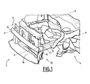
- FIG. 1 The front part of the structure of a motor vehicle 2 according to the invention is illustrated on the figure 1 .
- This vehicle comprises a chassis 4 and a bumper 6 fixed to the chassis 4.
- the chassis 4 is mounted on four wheels. It is suitable for carrying the vehicle's drive motor as well as the bodywork of the vehicle. It comprises two longitudinal members 8, 10 and cross members attached to the longitudinal members 8, 10.
- the bumper 6 comprises an upper beam 12, two shock absorbers 14, 16 fixed on the rear face of the upper beam 12, and a lower beam 18 fixed to the longitudinal members 8, 10.
- the upper beam 12 extends about 50 cm from the ground and protrudes from the body of the motor vehicle 2. It is adapted to come into contact with obstacles or vehicles during a frontal impact.
- Two attachment tabs 22, 24 for attachment to the vehicle body are further secured in a central portion of the upper beam 12.
- the shock absorbers 14, 16 are adapted to absorb the mechanical energy by deformation during an impact. They are formed by a corrugated iron block. They extend along the longitudinal axis A-A of the longitudinal members 8, 10.
- the lower beam 18 is intended to come into contact with a shin of a pedestrian in the event of impact with it. It extends parallel to the upper beam 12. It is located about 30 cm from the ground.
- the lower beam 18 is carried only by the longitudinal members 8, 10.
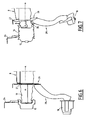
- Two sets of deformable support 25 are adapted to each attach an end of the lower beam 18 to a spar 8, 10.
- Each support assembly 25 comprises an upper repair plate 26 secured to the end face 27 of a spar 8, a connecting strap 28 connected to the upper plate 26, and a bottom repair plate 30 attached to the ramp.
- the upper plate 26 is formed of a steel plate. It has a rear main face 32 bolted to the end face 27 of a spar 8, and a front main face 36 to which a shock absorber 14, 16 applies.
- the upper plate 26 comprises a fixing portion 34 which protrudes below the spar, in a plane perpendicular to the longitudinal axis A-A of the spar.
- the connecting strap 28 is adapted to carry the lower beam 18 so that the latter is positioned in front of the upper beam 12, so that during an impact, the lower beam 18 is in contact with the tibia d. a pedestrian before the upper beam 12 touches the knee of it.
- the connecting strap 28 extends towards the front of the vehicle, along the longitudinal axis AA of the longitudinal members 8, 10, over a distance D of between 90 and 130 mm.
- the distance D is equal to 110 mm.
- the connecting strap 28 has a generally curved rounded shape forward. It is slightly curved in the other direction at its lower end 38.
- the connecting strap 28 has a U-shaped section having a base of width L approximately equal to 40 mm, and two branches whose height H varies substantially continuously along the ramp.
- the upper portion 40 of the ramp 28, located after mounting next to the upper repair plate 26, has a height H greater than that of the lower portion 42 of the ramp, located next to the lower repair plate 30.
- the height H of the branches of the U-shaped section of the upper portion 40 is between 30 and 40 mm.
- the height of the branches of the U-shaped section of the lower portion 42 is between 15 and 25 mm.
- the U-shaped section of the connecting straps 28 makes it possible to obtain rigid holding and holding of the lower beam 18 during shocks.
- the fastening strap 28 is fixed to the front face 36 of the fastening portion 34 of the upper plate by two welding beads.
- the bottom repair plate 30 has a rear main face 44 welded to the lower end of the connecting strap 28 by two weld beads, and a front main face 46 on which one end of the lower beam 18 is bolted.
- the attachment portion 34 of the upper plate 26 is deformed by bending about a transverse axis.
- the upper plate 26 flexes and absorbs some of the energy of the shock.
- the connecting straps 28 pivot about the deformation axis of the upper plate 26.
- the protection system described above is lightweight and has few parts, while providing the pedestrian protection function. It is easier to mount and economical.
Landscapes
- Engineering & Computer Science (AREA)
- Mechanical Engineering (AREA)
- Body Structure For Vehicles (AREA)
Claims (8)
- Kraftfahrzeug (2) umfassend ein Fahrgestell (4) mit zwei Längsträgern (8, 10) und einer Stoßstange (6), die vom Fahrgestell (4) gehalten wird, wobei die Stoßstange (6) einen oberen Träger (12) umfasst, der über einen Stoßabsorber (14, 16) mit dem vorderen Ende eines jeden Längsträgers (8, 10) verbunden ist, und einen unteren Träger (18), der angepasst ist, um mit einem Schienbein eines Fußgängers in Kontakt zu treten,
wobei jeder Endabschnitt des unteren Trägers (18) am Ende einer verformbaren Trageeinheit (25) befestigt ist, und jede Trageeinheit (25) ein Verbindungsstück (28) umfasst, das mit dem unteren Träger (18) verbunden ist, sowie eine Platte (26), die auf dem Verbindungsstück (28) befestigt, und kraftschlüssig mit dem Ende (27) eines Längsträgers (8, 10) verbunden ist, der so zugeordnet ist, dass die Platte (26) zwischen dem Längsträger (8, 10) und dem Stoßabsorber (14, 16) angeordnet ist. - Kraftfahrzeug (2) nach Anspruch 1, dadurch gekennzeichnet, dass jedes der Verbindungsstücke (28) steif ist, während jede Platte (26) unterhalb des Längsträgers (8, 10) einen Abschnitt (34) zur Befestigung des Verbindungsstückes (28) umfasst, die angepasst ist, um unter Einwirkung eines Stoßes nach hinten nachzugeben.
- Kraftfahrzeug (2) nach Anspruch 2, dadurch gekennzeichnet, dass der besagte Befestigungsabschnitt (34) der Platte (26) bei einem Stoß geeignet ist, um eine in Achse nachzugeben, die in etwa senkrecht zur Längsachse (A-A) der Längsträger (8, 10) steht, und dadurch, dass das Verbindungsstück (28) geeignet ist, um diese Achse nachzugeben.
- Kraftfahrzeug (2) nach irgendeinem der Ansprüche 1 bis 3, dadurch gekennzeichnet, dass jedes der Verbindungsstücke (28) einen Querschnitt in Form eines U aufweist, und dadurch, dass die an den Längsträger (8, 10) angrenzenden Äste des U eine Höhe (H) aufweisen, die größer ist, als jene der Äste des U, die an den unteren Träger (18) angrenzen.
- Kraftfahrzeug (2) nach irgendeinem der Ansprüche 1 bis 4, dadurch gekennzeichnet, dass jedes der Verbindungsstücke (28) eine allgemein gebogene und nach vorne gewölbte Form aufweist, wobei das besagte Verbindungsstück (28) an seinem unteren Ende (38) in die entgegengesetzte Richtung gebogen ist.
- Kraftfahrzeug (2) nach irgendeinem der Ansprüche 1 bis 5, dadurch gekennzeichnet, dass sich der besagte Befestigungsabschnitt (34) der Platte (26) über eine Ebene erstreckt, die normal zur Längsachse (A-A) der Längsträger (8, 10) steht.
- Kraftfahrzeug (2) nach irgendeinem der Ansprüche 1 bis 6, dadurch gekennzeichnet, dass die Platte (26) aus Stahl gefertigt ist, und eine rückwärtige Hauptseite (32) umfasst, die an einem Ende (27) eines Längsträgers (8, 10) befestigt ist, und eine vordere Hauptseite (36), auf der der Stoßabsorber (14, 16) anliegt.
- Kraftfahrzeug (2) nach irgendeinem der Ansprüche 2 bis 7, dadurch gekennzeichnet, dass das Verbindungsstück (28) durch Verschweißen am Befestigungsabschnitt (34) der Platte (26) befestigt ist.
Applications Claiming Priority (2)
| Application Number | Priority Date | Filing Date | Title |
|---|---|---|---|
| FR0757491A FR2920725B1 (fr) | 2007-09-11 | 2007-09-11 | Vehicule automobile |
| PCT/FR2008/051563 WO2009044035A1 (fr) | 2007-09-11 | 2008-09-03 | Pare-chocs pour vehicule automobile |
Publications (2)
| Publication Number | Publication Date |
|---|---|
| EP2185384A1 EP2185384A1 (de) | 2010-05-19 |
| EP2185384B1 true EP2185384B1 (de) | 2012-10-31 |
Family
ID=39327273
Family Applications (1)
| Application Number | Title | Priority Date | Filing Date |
|---|---|---|---|
| EP08836278A Active EP2185384B1 (de) | 2007-09-11 | 2008-09-03 | Puffer für automobile |
Country Status (4)
| Country | Link |
|---|---|
| EP (1) | EP2185384B1 (de) |
| ES (1) | ES2394394T3 (de) |
| FR (1) | FR2920725B1 (de) |
| WO (1) | WO2009044035A1 (de) |
Families Citing this family (2)
| Publication number | Priority date | Publication date | Assignee | Title |
|---|---|---|---|---|
| FR2966103B1 (fr) * | 2010-10-13 | 2015-07-17 | Peugeot Citroen Automobiles Sa | Partie avant de la caisse d'un vehicule automobile comportant deux bretelles reliant la traverse superieure a la traverse inferieure et vehicule ainsi equipe |
| CN103786668A (zh) * | 2013-12-19 | 2014-05-14 | 柳州市京阳节能科技研发有限公司 | 汽车头安全防撞底架装置 |
Family Cites Families (6)
| Publication number | Priority date | Publication date | Assignee | Title |
|---|---|---|---|---|
| US6634702B1 (en) * | 1999-06-23 | 2003-10-21 | Dynamit Nobel Kunstsoff Gmbh | Front-end module for a motor vehicle |
| EP1065108B1 (de) * | 1999-06-28 | 2004-04-21 | Mazda Motor Corporation | Kraftfahrzeug- Vorderwagenaufbau |
| US6485072B1 (en) * | 1999-12-15 | 2002-11-26 | Ford Global Technologies, Inc. | Bumper system for motor vehicles |
| DE10100875B4 (de) * | 2001-01-11 | 2008-06-26 | Benteler Automobiltechnik Gmbh | Stossfängeranordnung |
| US6513843B1 (en) * | 2002-02-21 | 2003-02-04 | Ford Global Technologies, Inc. | Pedestrian protection leg spoiler |
| JP2005306161A (ja) * | 2004-04-20 | 2005-11-04 | Asteer Co Ltd | バンパ装置 |
-
2007
- 2007-09-11 FR FR0757491A patent/FR2920725B1/fr not_active Expired - Fee Related
-
2008
- 2008-09-03 WO PCT/FR2008/051563 patent/WO2009044035A1/fr active Application Filing
- 2008-09-03 ES ES08836278T patent/ES2394394T3/es active Active
- 2008-09-03 EP EP08836278A patent/EP2185384B1/de active Active
Also Published As
| Publication number | Publication date |
|---|---|
| ES2394394T3 (es) | 2013-01-31 |
| WO2009044035A1 (fr) | 2009-04-09 |
| FR2920725A1 (fr) | 2009-03-13 |
| FR2920725B1 (fr) | 2010-05-14 |
| EP2185384A1 (de) | 2010-05-19 |
Similar Documents
| Publication | Publication Date | Title |
|---|---|---|
| EP1942033B1 (de) | Auflagerteil für Stoßdämpfersystem, das für die Montage am Ende eines Längsträgers eines Kraftfahrzeugs bestimmt ist | |
| EP1874613B1 (de) | Fondboden eines automobils | |
| FR2508398A1 (fr) | Pare-chocs pour vehicules automobiles | |
| GB2395931A (en) | Vehicle front body structure | |
| EP1314614B1 (de) | Stossfängeranordnung für Kraftfahrzeuge | |
| WO2010062293A1 (en) | Snowmobile frame | |
| FR2914900A1 (fr) | Traverse de planche de bord de vehicule automobile et vehicule automobile correspondant. | |
| EP2185384B1 (de) | Puffer für automobile | |
| EP2443021B1 (de) | Vorrichtung zur befestigung des voderen stossfängers eines fahrzeugaufbaus | |
| FR2883245A1 (fr) | Dispositif de liaison entre un support de colonne de direction et un element de structure, traverse et vehicule automobile associe. | |
| WO2008090274A1 (fr) | Dispositif de liaison de deux éléments de structure de véhicule automobile | |
| EP1693283B1 (de) | Vorderbau für ein Kraftfahrzeug | |
| EP1809526B1 (de) | Verbindungsvorrichtung zwischen einer lenksäule und einem kraftfahrzeugaufbau | |
| EP1660364B1 (de) | Kraftfahrzeugvorderteilkonstruktion | |
| JP3182973B2 (ja) | フロントボデーの構造 | |
| EP2207709B1 (de) | Automobil mit einer querstange, einer technischen vorderfläche und einem konvergierenden element, die miteinander verbunden sind | |
| FR2990920A1 (fr) | Dispositif de structure destine a etre monte sur un element de chassis de vehicule automobile | |
| EP1937537B1 (de) | Vorderstruktur für ein kraftfahrzeug zur verhinderung des eindringens eines rades in den passagierraum im falle eines frontalen aufpralls | |
| EP1847445B1 (de) | Struktur vor einem Kraftfahrzeug und ein entsprechendes Verfahren | |
| FR3065417A1 (fr) | Ensemble d'extremite notamment arriere d'un vehicule automobile | |
| WO2023079218A1 (fr) | Ensemble de protection avant pour véhicule automobile | |
| FR2882327A1 (fr) | Structure avant de vehicule automobile | |
| WO2024061647A1 (fr) | Dispositif formant marchepied d'un véhicule automobile | |
| FR2926052A1 (fr) | Structure avant de vehicule automobile. | |
| JP2929988B2 (ja) | 車両用バンパの取付構造 |
Legal Events
| Date | Code | Title | Description |
|---|---|---|---|
| PUAI | Public reference made under article 153(3) epc to a published international application that has entered the european phase |
Free format text: ORIGINAL CODE: 0009012 |
|
| 17P | Request for examination filed |
Effective date: 20091210 |
|
| AK | Designated contracting states |
Kind code of ref document: A1 Designated state(s): AT BE BG CH CY CZ DE DK EE ES FI FR GB GR HR HU IE IS IT LI LT LU LV MC MT NL NO PL PT RO SE SI SK TR |
|
| AX | Request for extension of the european patent |
Extension state: AL BA MK RS |
|
| DAX | Request for extension of the european patent (deleted) | ||
| GRAP | Despatch of communication of intention to grant a patent |
Free format text: ORIGINAL CODE: EPIDOSNIGR1 |
|
| GRAS | Grant fee paid |
Free format text: ORIGINAL CODE: EPIDOSNIGR3 |
|
| GRAA | (expected) grant |
Free format text: ORIGINAL CODE: 0009210 |
|
| AK | Designated contracting states |
Kind code of ref document: B1 Designated state(s): AT BE BG CH CY CZ DE DK EE ES FI FR GB GR HR HU IE IS IT LI LT LU LV MC MT NL NO PL PT RO SE SI SK TR |
|
| REG | Reference to a national code |
Ref country code: GB Ref legal event code: FG4D Free format text: NOT ENGLISH Ref country code: CH Ref legal event code: EP |
|
| REG | Reference to a national code |
Ref country code: AT Ref legal event code: REF Ref document number: 581808 Country of ref document: AT Kind code of ref document: T Effective date: 20121115 |
|
| REG | Reference to a national code |
Ref country code: IE Ref legal event code: FG4D Free format text: LANGUAGE OF EP DOCUMENT: FRENCH |
|
| REG | Reference to a national code |
Ref country code: DE Ref legal event code: R096 Ref document number: 602008019858 Country of ref document: DE Effective date: 20121227 |
|
| REG | Reference to a national code |
Ref country code: ES Ref legal event code: FG2A Ref document number: 2394394 Country of ref document: ES Kind code of ref document: T3 Effective date: 20130131 |
|
| REG | Reference to a national code |
Ref country code: SK Ref legal event code: T3 Ref document number: E 12953 Country of ref document: SK |
|
| REG | Reference to a national code |
Ref country code: ES Ref legal event code: GC2A Effective date: 20130213 |
|
| REG | Reference to a national code |
Ref country code: AT Ref legal event code: MK05 Ref document number: 581808 Country of ref document: AT Kind code of ref document: T Effective date: 20121031 |
|
| REG | Reference to a national code |
Ref country code: LT Ref legal event code: MG4D |
|
| REG | Reference to a national code |
Ref country code: NL Ref legal event code: VDEP Effective date: 20121031 |
|
| PG25 | Lapsed in a contracting state [announced via postgrant information from national office to epo] |
Ref country code: FI Free format text: LAPSE BECAUSE OF FAILURE TO SUBMIT A TRANSLATION OF THE DESCRIPTION OR TO PAY THE FEE WITHIN THE PRESCRIBED TIME-LIMIT Effective date: 20121031 Ref country code: LT Free format text: LAPSE BECAUSE OF FAILURE TO SUBMIT A TRANSLATION OF THE DESCRIPTION OR TO PAY THE FEE WITHIN THE PRESCRIBED TIME-LIMIT Effective date: 20121031 Ref country code: IS Free format text: LAPSE BECAUSE OF FAILURE TO SUBMIT A TRANSLATION OF THE DESCRIPTION OR TO PAY THE FEE WITHIN THE PRESCRIBED TIME-LIMIT Effective date: 20130228 Ref country code: NL Free format text: LAPSE BECAUSE OF FAILURE TO SUBMIT A TRANSLATION OF THE DESCRIPTION OR TO PAY THE FEE WITHIN THE PRESCRIBED TIME-LIMIT Effective date: 20121031 Ref country code: SE Free format text: LAPSE BECAUSE OF FAILURE TO SUBMIT A TRANSLATION OF THE DESCRIPTION OR TO PAY THE FEE WITHIN THE PRESCRIBED TIME-LIMIT Effective date: 20121031 Ref country code: NO Free format text: LAPSE BECAUSE OF FAILURE TO SUBMIT A TRANSLATION OF THE DESCRIPTION OR TO PAY THE FEE WITHIN THE PRESCRIBED TIME-LIMIT Effective date: 20130131 Ref country code: HR Free format text: LAPSE BECAUSE OF FAILURE TO SUBMIT A TRANSLATION OF THE DESCRIPTION OR TO PAY THE FEE WITHIN THE PRESCRIBED TIME-LIMIT Effective date: 20121031 |
|
| PG25 | Lapsed in a contracting state [announced via postgrant information from national office to epo] |
Ref country code: LV Free format text: LAPSE BECAUSE OF FAILURE TO SUBMIT A TRANSLATION OF THE DESCRIPTION OR TO PAY THE FEE WITHIN THE PRESCRIBED TIME-LIMIT Effective date: 20121031 Ref country code: PL Free format text: LAPSE BECAUSE OF FAILURE TO SUBMIT A TRANSLATION OF THE DESCRIPTION OR TO PAY THE FEE WITHIN THE PRESCRIBED TIME-LIMIT Effective date: 20121031 Ref country code: SI Free format text: LAPSE BECAUSE OF FAILURE TO SUBMIT A TRANSLATION OF THE DESCRIPTION OR TO PAY THE FEE WITHIN THE PRESCRIBED TIME-LIMIT Effective date: 20121031 Ref country code: PT Free format text: LAPSE BECAUSE OF FAILURE TO SUBMIT A TRANSLATION OF THE DESCRIPTION OR TO PAY THE FEE WITHIN THE PRESCRIBED TIME-LIMIT Effective date: 20130228 Ref country code: GR Free format text: LAPSE BECAUSE OF FAILURE TO SUBMIT A TRANSLATION OF THE DESCRIPTION OR TO PAY THE FEE WITHIN THE PRESCRIBED TIME-LIMIT Effective date: 20130201 |
|
| PG25 | Lapsed in a contracting state [announced via postgrant information from national office to epo] |
Ref country code: AT Free format text: LAPSE BECAUSE OF FAILURE TO SUBMIT A TRANSLATION OF THE DESCRIPTION OR TO PAY THE FEE WITHIN THE PRESCRIBED TIME-LIMIT Effective date: 20121031 |
|
| REG | Reference to a national code |
Ref country code: GB Ref legal event code: 746 Effective date: 20130611 |
|
| PG25 | Lapsed in a contracting state [announced via postgrant information from national office to epo] |
Ref country code: CZ Free format text: LAPSE BECAUSE OF FAILURE TO SUBMIT A TRANSLATION OF THE DESCRIPTION OR TO PAY THE FEE WITHIN THE PRESCRIBED TIME-LIMIT Effective date: 20121031 Ref country code: DK Free format text: LAPSE BECAUSE OF FAILURE TO SUBMIT A TRANSLATION OF THE DESCRIPTION OR TO PAY THE FEE WITHIN THE PRESCRIBED TIME-LIMIT Effective date: 20121031 Ref country code: EE Free format text: LAPSE BECAUSE OF FAILURE TO SUBMIT A TRANSLATION OF THE DESCRIPTION OR TO PAY THE FEE WITHIN THE PRESCRIBED TIME-LIMIT Effective date: 20121031 Ref country code: BG Free format text: LAPSE BECAUSE OF FAILURE TO SUBMIT A TRANSLATION OF THE DESCRIPTION OR TO PAY THE FEE WITHIN THE PRESCRIBED TIME-LIMIT Effective date: 20130131 |
|
| REG | Reference to a national code |
Ref country code: DE Ref legal event code: R084 Ref document number: 602008019858 Country of ref document: DE Effective date: 20130607 |
|
| PG25 | Lapsed in a contracting state [announced via postgrant information from national office to epo] |
Ref country code: RO Free format text: LAPSE BECAUSE OF FAILURE TO SUBMIT A TRANSLATION OF THE DESCRIPTION OR TO PAY THE FEE WITHIN THE PRESCRIBED TIME-LIMIT Effective date: 20121031 Ref country code: IT Free format text: LAPSE BECAUSE OF FAILURE TO SUBMIT A TRANSLATION OF THE DESCRIPTION OR TO PAY THE FEE WITHIN THE PRESCRIBED TIME-LIMIT Effective date: 20121031 |
|
| PLBE | No opposition filed within time limit |
Free format text: ORIGINAL CODE: 0009261 |
|
| STAA | Information on the status of an ep patent application or granted ep patent |
Free format text: STATUS: NO OPPOSITION FILED WITHIN TIME LIMIT |
|
| RAP2 | Party data changed (patent owner data changed or rights of a patent transferred) |
Owner name: PEUGEOT CITROEN AUTOMOBILES SA Owner name: GM GLOBAL TECHNOLOGY OPERATIONS LLC |
|
| 26N | No opposition filed |
Effective date: 20130801 |
|
| REG | Reference to a national code |
Ref country code: DE Ref legal event code: R097 Ref document number: 602008019858 Country of ref document: DE Effective date: 20130801 |
|
| PG25 | Lapsed in a contracting state [announced via postgrant information from national office to epo] |
Ref country code: CY Free format text: LAPSE BECAUSE OF FAILURE TO SUBMIT A TRANSLATION OF THE DESCRIPTION OR TO PAY THE FEE WITHIN THE PRESCRIBED TIME-LIMIT Effective date: 20121031 |
|
| BERE | Be: lapsed |
Owner name: PEUGEOT CITROEN AUTOMOBILES SA Effective date: 20130930 |
|
| PG25 | Lapsed in a contracting state [announced via postgrant information from national office to epo] |
Ref country code: MC Free format text: LAPSE BECAUSE OF FAILURE TO SUBMIT A TRANSLATION OF THE DESCRIPTION OR TO PAY THE FEE WITHIN THE PRESCRIBED TIME-LIMIT Effective date: 20121031 |
|
| REG | Reference to a national code |
Ref country code: CH Ref legal event code: PL |
|
| REG | Reference to a national code |
Ref country code: IE Ref legal event code: MM4A |
|
| PG25 | Lapsed in a contracting state [announced via postgrant information from national office to epo] |
Ref country code: IE Free format text: LAPSE BECAUSE OF NON-PAYMENT OF DUE FEES Effective date: 20130903 Ref country code: LI Free format text: LAPSE BECAUSE OF NON-PAYMENT OF DUE FEES Effective date: 20130930 Ref country code: BE Free format text: LAPSE BECAUSE OF NON-PAYMENT OF DUE FEES Effective date: 20130930 Ref country code: CH Free format text: LAPSE BECAUSE OF NON-PAYMENT OF DUE FEES Effective date: 20130930 |
|
| REG | Reference to a national code |
Ref country code: FR Ref legal event code: TQ Owner name: GM GLOBAL TECHNOLOGY OPERATIONS LLC, US Effective date: 20140725 Ref country code: FR Ref legal event code: TQ Owner name: PEUGEOT CITROEN AUTOMOBILES SA, FR Effective date: 20140725 |
|
| REG | Reference to a national code |
Ref country code: FR Ref legal event code: TP Owner name: PEUGEOT CITROEN AUTOMOBILES SA, FR Effective date: 20150225 |
|
| PG25 | Lapsed in a contracting state [announced via postgrant information from national office to epo] |
Ref country code: TR Free format text: LAPSE BECAUSE OF FAILURE TO SUBMIT A TRANSLATION OF THE DESCRIPTION OR TO PAY THE FEE WITHIN THE PRESCRIBED TIME-LIMIT Effective date: 20121031 Ref country code: MT Free format text: LAPSE BECAUSE OF FAILURE TO SUBMIT A TRANSLATION OF THE DESCRIPTION OR TO PAY THE FEE WITHIN THE PRESCRIBED TIME-LIMIT Effective date: 20121031 |
|
| PG25 | Lapsed in a contracting state [announced via postgrant information from national office to epo] |
Ref country code: LU Free format text: LAPSE BECAUSE OF NON-PAYMENT OF DUE FEES Effective date: 20130903 Ref country code: HU Free format text: LAPSE BECAUSE OF FAILURE TO SUBMIT A TRANSLATION OF THE DESCRIPTION OR TO PAY THE FEE WITHIN THE PRESCRIBED TIME-LIMIT; INVALID AB INITIO Effective date: 20080903 |
|
| REG | Reference to a national code |
Ref country code: FR Ref legal event code: PLFP Year of fee payment: 9 |
|
| REG | Reference to a national code |
Ref country code: FR Ref legal event code: PLFP Year of fee payment: 10 |
|
| REG | Reference to a national code |
Ref country code: FR Ref legal event code: CA Effective date: 20180312 Ref country code: FR Ref legal event code: CD Owner name: PEUGEOT CITROEN AUTOMOBILES SA, FR Effective date: 20180312 |
|
| REG | Reference to a national code |
Ref country code: FR Ref legal event code: PLFP Year of fee payment: 11 |
|
| PGFP | Annual fee paid to national office [announced via postgrant information from national office to epo] |
Ref country code: GB Payment date: 20230823 Year of fee payment: 16 |
|
| PGFP | Annual fee paid to national office [announced via postgrant information from national office to epo] |
Ref country code: SK Payment date: 20230830 Year of fee payment: 16 Ref country code: FR Payment date: 20230822 Year of fee payment: 16 Ref country code: DE Payment date: 20230822 Year of fee payment: 16 |
|
| PGFP | Annual fee paid to national office [announced via postgrant information from national office to epo] |
Ref country code: ES Payment date: 20231002 Year of fee payment: 16 |