EP2185384B1 - Bumpers for automobile - Google Patents
Bumpers for automobile Download PDFInfo
- Publication number
- EP2185384B1 EP2185384B1 EP08836278A EP08836278A EP2185384B1 EP 2185384 B1 EP2185384 B1 EP 2185384B1 EP 08836278 A EP08836278 A EP 08836278A EP 08836278 A EP08836278 A EP 08836278A EP 2185384 B1 EP2185384 B1 EP 2185384B1
- Authority
- EP
- European Patent Office
- Prior art keywords
- motor vehicle
- plate
- connecting part
- longitudinal
- attached
- Prior art date
- Legal status (The legal status is an assumption and is not a legal conclusion. Google has not performed a legal analysis and makes no representation as to the accuracy of the status listed.)
- Active
Links
- 230000035939 shock Effects 0.000 claims description 15
- 239000006096 absorbing agent Substances 0.000 claims description 12
- 229910000831 Steel Inorganic materials 0.000 claims description 2
- 239000010959 steel Substances 0.000 claims description 2
- 210000002303 tibia Anatomy 0.000 claims description 2
- 238000003466 welding Methods 0.000 claims description 2
- 210000003127 knee Anatomy 0.000 description 3
- BASFCYQUMIYNBI-UHFFFAOYSA-N platinum Chemical compound [Pt] BASFCYQUMIYNBI-UHFFFAOYSA-N 0.000 description 3
- XEEYBQQBJWHFJM-UHFFFAOYSA-N Iron Chemical compound [Fe] XEEYBQQBJWHFJM-UHFFFAOYSA-N 0.000 description 2
- 239000011324 bead Substances 0.000 description 2
- 208000016593 Knee injury Diseases 0.000 description 1
- 238000005452 bending Methods 0.000 description 1
- 229910052742 iron Inorganic materials 0.000 description 1
- 210000002414 leg Anatomy 0.000 description 1
Images

Classifications
-
- B—PERFORMING OPERATIONS; TRANSPORTING
- B60—VEHICLES IN GENERAL
- B60R—VEHICLES, VEHICLE FITTINGS, OR VEHICLE PARTS, NOT OTHERWISE PROVIDED FOR
- B60R19/00—Wheel guards; Radiator guards, e.g. grilles; Obstruction removers; Fittings damping bouncing force in collisions
- B60R19/02—Bumpers, i.e. impact receiving or absorbing members for protecting vehicles or fending off blows from other vehicles or objects
- B60R19/04—Bumpers, i.e. impact receiving or absorbing members for protecting vehicles or fending off blows from other vehicles or objects formed from more than one section in a side-by-side arrangement
- B60R19/12—Bumpers, i.e. impact receiving or absorbing members for protecting vehicles or fending off blows from other vehicles or objects formed from more than one section in a side-by-side arrangement vertically spaced
-
- B—PERFORMING OPERATIONS; TRANSPORTING
- B60—VEHICLES IN GENERAL
- B60R—VEHICLES, VEHICLE FITTINGS, OR VEHICLE PARTS, NOT OTHERWISE PROVIDED FOR
- B60R19/00—Wheel guards; Radiator guards, e.g. grilles; Obstruction removers; Fittings damping bouncing force in collisions
- B60R19/02—Bumpers, i.e. impact receiving or absorbing members for protecting vehicles or fending off blows from other vehicles or objects
- B60R19/24—Arrangements for mounting bumpers on vehicles
- B60R19/26—Arrangements for mounting bumpers on vehicles comprising yieldable mounting means
-
- B—PERFORMING OPERATIONS; TRANSPORTING
- B60—VEHICLES IN GENERAL
- B60R—VEHICLES, VEHICLE FITTINGS, OR VEHICLE PARTS, NOT OTHERWISE PROVIDED FOR
- B60R21/00—Arrangements or fittings on vehicles for protecting or preventing injuries to occupants or pedestrians in case of accidents or other traffic risks
- B60R2021/003—Arrangements or fittings on vehicles for protecting or preventing injuries to occupants or pedestrians in case of accidents or other traffic risks characterised by occupant or pedestian
- B60R2021/0039—Body parts of the occupant or pedestrian affected by the accident
- B60R2021/0053—Legs
-
- B—PERFORMING OPERATIONS; TRANSPORTING
- B60—VEHICLES IN GENERAL
- B60R—VEHICLES, VEHICLE FITTINGS, OR VEHICLE PARTS, NOT OTHERWISE PROVIDED FOR
- B60R21/00—Arrangements or fittings on vehicles for protecting or preventing injuries to occupants or pedestrians in case of accidents or other traffic risks
- B60R21/34—Protecting non-occupants of a vehicle, e.g. pedestrians
Definitions
- the present invention relates to a motor vehicle, of the type comprising a frame comprising two longitudinal members, and a bumper carried by the frame, the bumper comprising an upper beam connected to the front end of each spar by a shock absorber, and a lower beam adapted to engage a shin of a pedestrian.
- Motor vehicles are currently equipped with a bumper comprising an upper beam and a lower beam.
- the latter is generally called low pedestrian support.
- the upper beam forms a projecting portion located about 50 cm from the ground. It is particular suitable to coincide with the upper beam of the bumper of another vehicle in the event of a collision.
- the upper beam is attached to shock absorbers each mounted on a repair plate affixed to the end of each spar of the vehicle.
- the lower beam is adapted to come into contact with the shin of a pedestrian in the event of a pedestrian impact. It reduces the severity of knee injuries resulting from the pressure of the upper beam on the knee.
- the upper beam assembly and its absorbers and / or the lower beam can be easily replaced.
- the document EP 1 108 622 A2 discloses a motor vehicle, of the type comprising a frame comprising two longitudinal members, and a bumper carried by the frame.
- the bumper comprises an upper beam connected to the front end of each spar, and a lower beam adapted to come into contact with a shin of a pedestrian.
- Each end portion of the lower beam is attached to the end of a deformable support assembly, each support assembly including a connecting piece connected to the lower beam.
- the object of the invention is to provide a particularly light solution that satisfactorily provides high-speed frontal protection, repairability and pedestrian protection functions.
- the invention relates to a motor vehicle of the type mentioned above, in which each end portion of the lower beam is fixed to the end of a deformable support assembly, each support assembly comprising a connecting piece connected to the lower beam, and a plate fixed to the connecting piece and secured to the end of a spar associated so that the plate is disposed between the spar and the shock absorber.
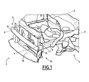
- FIG. 1 The front part of the structure of a motor vehicle 2 according to the invention is illustrated on the figure 1 .
- This vehicle comprises a chassis 4 and a bumper 6 fixed to the chassis 4.
- the chassis 4 is mounted on four wheels. It is suitable for carrying the vehicle's drive motor as well as the bodywork of the vehicle. It comprises two longitudinal members 8, 10 and cross members attached to the longitudinal members 8, 10.
- the bumper 6 comprises an upper beam 12, two shock absorbers 14, 16 fixed on the rear face of the upper beam 12, and a lower beam 18 fixed to the longitudinal members 8, 10.
- the upper beam 12 extends about 50 cm from the ground and protrudes from the body of the motor vehicle 2. It is adapted to come into contact with obstacles or vehicles during a frontal impact.
- Two attachment tabs 22, 24 for attachment to the vehicle body are further secured in a central portion of the upper beam 12.
- the shock absorbers 14, 16 are adapted to absorb the mechanical energy by deformation during an impact. They are formed by a corrugated iron block. They extend along the longitudinal axis A-A of the longitudinal members 8, 10.
- the lower beam 18 is intended to come into contact with a shin of a pedestrian in the event of impact with it. It extends parallel to the upper beam 12. It is located about 30 cm from the ground.
- the lower beam 18 is carried only by the longitudinal members 8, 10.
- Two sets of deformable support 25 are adapted to each attach an end of the lower beam 18 to a spar 8, 10.
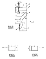
- Each support assembly 25 comprises an upper repair plate 26 secured to the end face 27 of a spar 8, a connecting strap 28 connected to the upper plate 26, and a bottom repair plate 30 attached to the ramp.
- the upper plate 26 is formed of a steel plate. It has a rear main face 32 bolted to the end face 27 of a spar 8, and a front main face 36 to which a shock absorber 14, 16 applies.
- the upper plate 26 comprises a fixing portion 34 which protrudes below the spar, in a plane perpendicular to the longitudinal axis A-A of the spar.
- the connecting strap 28 is adapted to carry the lower beam 18 so that the latter is positioned in front of the upper beam 12, so that during an impact, the lower beam 18 is in contact with the tibia d. a pedestrian before the upper beam 12 touches the knee of it.
- the connecting strap 28 extends towards the front of the vehicle, along the longitudinal axis AA of the longitudinal members 8, 10, over a distance D of between 90 and 130 mm.
- the distance D is equal to 110 mm.
- the connecting strap 28 has a generally curved rounded shape forward. It is slightly curved in the other direction at its lower end 38.
- the connecting strap 28 has a U-shaped section having a base of width L approximately equal to 40 mm, and two branches whose height H varies substantially continuously along the ramp.
- the upper portion 40 of the ramp 28, located after mounting next to the upper repair plate 26, has a height H greater than that of the lower portion 42 of the ramp, located next to the lower repair plate 30.
- the height H of the branches of the U-shaped section of the upper portion 40 is between 30 and 40 mm.
- the height of the branches of the U-shaped section of the lower portion 42 is between 15 and 25 mm.
- the U-shaped section of the connecting straps 28 makes it possible to obtain rigid holding and holding of the lower beam 18 during shocks.
- the fastening strap 28 is fixed to the front face 36 of the fastening portion 34 of the upper plate by two welding beads.
- the bottom repair plate 30 has a rear main face 44 welded to the lower end of the connecting strap 28 by two weld beads, and a front main face 46 on which one end of the lower beam 18 is bolted.
- the attachment portion 34 of the upper plate 26 is deformed by bending about a transverse axis.
- the upper plate 26 flexes and absorbs some of the energy of the shock.
- the connecting straps 28 pivot about the deformation axis of the upper plate 26.
- the protection system described above is lightweight and has few parts, while providing the pedestrian protection function. It is easier to mount and economical.
Landscapes
- Engineering & Computer Science (AREA)
- Mechanical Engineering (AREA)
- Body Structure For Vehicles (AREA)
Description
La présente invention concerne un véhicule automobile, du type comportant un châssis comprenant deux longerons, et un pare-chocs porté par le châssis, le pare-chocs comportant une poutre supérieure reliée à l'extrémité avant de chaque longeron par un absorbeur de chocs, et une poutre inférieure adaptée pour venir en contact avec un tibia d'un piéton.The present invention relates to a motor vehicle, of the type comprising a frame comprising two longitudinal members, and a bumper carried by the frame, the bumper comprising an upper beam connected to the front end of each spar by a shock absorber, and a lower beam adapted to engage a shin of a pedestrian.
Les véhicules automobiles sont actuellement équipés d'un pare-chocs comprenant une poutre supérieure et une poutre inférieure. Cette dernière est généralement appelée appui bas piéton.Motor vehicles are currently equipped with a bumper comprising an upper beam and a lower beam. The latter is generally called low pedestrian support.
La poutre supérieure forme une partie saillante située à environ 50 cm du sol. Elle est notamment propre à coïncider avec la poutre supérieure du pare-chocs d'un autre véhicule en cas de collision.The upper beam forms a projecting portion located about 50 cm from the ground. It is particular suitable to coincide with the upper beam of the bumper of another vehicle in the event of a collision.
La poutre supérieure est fixée à des absorbeurs de chocs montés chacun sur une platine de réparabilité fixée à l'extrémité de chaque longeron du véhicule.The upper beam is attached to shock absorbers each mounted on a repair plate affixed to the end of each spar of the vehicle.
La poutre inférieure est propre à venir en contact avec le tibia d'un piéton en cas de choc piéton. Elle permet de réduire la gravité des lésions au niveau du genou résultant de la pression de la poutre supérieure sur le genou.The lower beam is adapted to come into contact with the shin of a pedestrian in the event of a pedestrian impact. It reduces the severity of knee injuries resulting from the pressure of the upper beam on the knee.
Après un choc, l'ensemble poutre supérieure et ses absorbeurs et/ou la poutre inférieure peuvent être facilement remplacés.After a shock, the upper beam assembly and its absorbers and / or the lower beam can be easily replaced.
Le document
L'invention a pour but de proposer une solution particulièrement légère assurant de façon satisfaisante les fonctions de protection aux chocs frontaux à grande vitesse, de réparabilité et de protection des piétons.The object of the invention is to provide a particularly light solution that satisfactorily provides high-speed frontal protection, repairability and pedestrian protection functions.
Cet objet obtenu selon l'invention à l'aide d'un véhicule automobile selon la revendication 1.This object obtained according to the invention with the aid of a motor vehicle according to claim 1.
A cet effet, l'invention a pour objet un véhicule automobile du type mentionné ci-dessus, dans laquel chaque partie d'extrémité de la poutre inférieure est fixée à l'extrémité d'un ensemble de support déformable, chaque ensemble de support comprenant une pièce de liaison reliée à la poutre inférieure, et une platine fixée à la pièce de liaison et solidaire de l'extrémité d'un longeron associé de telle sorte que la platine est disposée entre le longeron et l'absorbeur de chocs.For this purpose, the invention relates to a motor vehicle of the type mentioned above, in which each end portion of the lower beam is fixed to the end of a deformable support assembly, each support assembly comprising a connecting piece connected to the lower beam, and a plate fixed to the connecting piece and secured to the end of a spar associated so that the plate is disposed between the spar and the shock absorber.
Suivant des modes particuliers de réalisation, le véhicule automobile comporte l'une ou plusieurs des caractéristiques suivantes :
- chaque pièce de liaison est rigide tandis que chaque platine comporte, en dessous du longeron, une portion de fixation de la pièce de liaison adaptée pour fléchir vers l'arrière sous l'effet d'un choc ;
- lors d'un choc, ladite portion de fixation de la platine est propre à fléchir autour d'un axe sensiblement perpendiculaire à l'axe longitudinal des longerons, et la pièce de liaison est propre à pivoter autour de cet axe ;
- chaque pièce de liaison présente une section en forme de U, et en ce que les branches du U adjacentes au longeron présentent une hauteur supérieure aux branches du U adjacentes à la poutre inférieure ;
- chaque pièce de liaison présente une forme générale arquée bombée vers l'avant, ladite pièce de liaison étant recourbée en sens inverse à son extrémité inférieure ; et
- ladite portion de fixation de la platine s'étend dans un plan perpendiculaire à l'axe longitudinal des longerons.
- each connecting piece is rigid while each plate comprises, below the spar, a fastening portion of the connecting piece adapted to flex backwards under the effect of a shock;
- during an impact, said fixing portion of the plate is adapted to bend around an axis substantially perpendicular to the longitudinal axis of the longitudinal members, and the connecting piece is adapted to pivot about this axis;
- each connecting piece has a U-shaped section, and in that the legs of the U adjacent to the spar have a height greater than the branches of the U adjacent to the lower beam;
- each connecting piece has a generally arched shape curved forwardly, said connecting piece being curved in opposite direction at its lower end; and
- said fixing portion of the plate extends in a plane perpendicular to the longitudinal axis of the longitudinal members.
L'invention sera mieux comprise à la lecture de la description qui va suivre, donnée uniquement à titre d'exemple et faite en se référant aux dessins annexés, sur lesquels :
- la
figure 1 est une vue en perspective de l'avant de la structure d'un véhicule automobile selon l'invention ; - la
figure 2 est une vue de face en perspective d'une partie d'un pare-chocs d'un véhicule automobile selon l'invention ; - la
figure 3 est une vue du côté de la partie du pare-chocs illustrée sur lafigure 2 ; - la
figure 4 est une vue en coupe de la pièce de liaison le long du plan IV-IV de lafigure 3 ; - la
figure 5 est une vue en coupe de la pièce de liaison le long du plan V-V de lafigure 3 ; et - les
figures 6 et 7 sont des vues de côté du pare-chocs du véhicule automobile avant et respectivement après déformation.
- the
figure 1 is a perspective view of the front of the structure of a motor vehicle according to the invention; - the
figure 2 is a perspective front view of a portion of a bumper of a motor vehicle according to the invention; - the
figure 3 is a side view of the part of the bumper shown on thefigure 2 ; - the
figure 4 is a sectional view of the connecting piece along the plane IV-IV of thefigure 3 ; - the
figure 5 is a sectional view of the connecting piece along the VV plane of thefigure 3 ; and - the
Figures 6 and 7 are side views of the bumper of the motor vehicle before and respectively after deformation.
Dans la suite de la description, les termes « avant », « arrière », « supérieur » et « inférieur » sont définis par rapport à l'orientation générale d'un véhicule automobile.In the remainder of the description, the terms "front", "rear", "upper" and "lower" are defined with respect to the general orientation of a motor vehicle.
La partie avant de la structure d'un véhicule automobile 2 selon l'invention est illustrée sur la
De façon classique, le châssis 4 est monté sur quatre roues. Il est propre à porter le moteur d'entraînement du véhicule ainsi que la carrosserie de celui-ci. Il comprend deux longerons 8, 10 et de traverses fixées aux longerons 8, 10.Conventionally, the chassis 4 is mounted on four wheels. It is suitable for carrying the vehicle's drive motor as well as the bodywork of the vehicle. It comprises two
Le pare-chocs 6 comprend une poutre supérieure 12, deux absorbeurs de chocs 14, 16 fixés sur la face arrière de la poutre supérieure 12, et une poutre inférieure 18 fixée aux longerons 8, 10.The bumper 6 comprises an
La poutre supérieure 12 s'étend à environ 50 cm du sol et forme une saillie par rapport à la carrosserie du véhicule automobile 2. Elle est propre à venir au contact des obstacles ou des véhicules lors d'un choc frontal.The
Deux pattes d'attache 22, 24 destinées à être accrochées à la carrosserie du véhicule sont en outre fixées dans une partie centrale de la poutre supérieure 12.Two
Les absorbeurs de chocs 14, 16 sont propres à absorber l'énergie mécanique par déformation lors d'un choc. Ils sont formés par un bloc en tôle ondulée. Ils s'étendent selon l'axe longitudinal A-A des longerons 8, 10.The
La poutre inférieure 18 est destinée à venir au contact d'un tibia d'un piéton en cas de choc avec celui-ci. Elle s'étend parallèlement à la poutre supérieure 12. Elle est située à environ 30 cm du sol.The
La poutre inférieure 18 est portée uniquement par les longerons 8, 10.The
Deux ensembles de support 25 déformables sont propres à fixer chacun une extrémité de la poutre inférieure 18 à un longeron 8, 10.Two sets of
Chaque ensemble de support 25 comprend une platine de réparabilité supérieure 26 solidaire de la face d'extrémité 27 d'un longeron 8, une bretelle de liaison 28 reliée à la platine supérieure 26, et une platine de réparabilité inférieure 30 fixée à la bretelle.Each
La platine supérieure 26 est formée d'une plaque d'acier. Elle présente une face principale arrière 32 boulonnée à la face d'extrémité 27 d'un longeron 8, et une face principale avant 36 sur laquelle s'applique un absorbeur de chocs 14, 16.The
La platine supérieure 26 comprend une portion de fixation 34 qui s'étend en saillie sous le longeron, dans un plan perpendiculaire à l'axe longitudinal A-A du longeron.The
La bretelle de liaison 28 est propre à porter la poutre inférieure 18 de façon à ce que cette dernière soit positionnée en avant de la poutre supérieure 12, de sorte que lors d'un choc, la poutre inférieure 18 soit en contact avec le tibia d'un piéton avant que la poutre supérieure 12 ne touche le genou de celui-ci.The connecting
A cet effet (
La bretelle de liaison 28 présente une forme générale arrondie bombée vers l'avant. Elle est légèrement recourbée dans l'autre sens à son extrémité inférieure 38.The connecting
La bretelle de liaison 28 présente une section en forme de U ayant une base de largeur L environ égale à 40 mm, et deux branches dont la hauteur H varie sensiblement continûment le long de la bretelle.The connecting
En particulier, la partie supérieure 40 de la bretelle 28, située après montage à côté de la plaque de réparabilité supérieure 26, présente une hauteur H supérieure à celle de la partie inférieure 42 de la bretelle, située à côté de la plaque de réparabilité inférieure 30.In particular, the
Comme visible sur les
La section en U des bretelles de liaison 28 permet d'obtenir une tenue et un maintien rigide de la poutre inférieure 18 lors des chocs.The U-shaped section of the connecting
La bretelle de fixation 28 est fixée à la face avant 36 de la portion de fixation 34 de la platine supérieure par deux cordons de soudure.The
La platine de réparabilité inférieure 30 présente une face principale arrière 44 soudée à l'extrémité inférieure de à la bretelle de liaison 28 par deux cordons de soudure, et une face principale avant 46 sur laquelle une extrémité de la poutre inférieure 18 est boulonnée.The
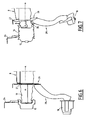
Lors d'un choc piéton, la poutre inférieure 18 vient en premier au contact du piéton, la portion de fixation 34 de la platine supérieure 26 se déforme par flexion autour d'un axe transversal. La platine supérieure 26 fléchit et absorbe une partie de l'énergie du choc.During a pedestrian impact, the
Les bretelles de liaison 28 pivotent autour de l'axe de déformation de la platine supérieure 26.The connecting straps 28 pivot about the deformation axis of the
Lorsque la poutre supérieure 12 vient en contact du genou du piéton, l'énergie du choc comprime les absorbeurs de chocs 14, 16 tandis que les bretelles de liaison 28 continuent de pivoter et s'effacent en dessous des absorbeurs 14, 16.When the
Le système de protection décrit ci-dessus est léger et comporte peu de pièces, tout en assurant la fonction de protection du piéton. Il est plus facile à monter et économique.The protection system described above is lightweight and has few parts, while providing the pedestrian protection function. It is easier to mount and economical.
Claims (8)
- A motor vehicle (2), of the type that includes a chassis (4) that has two longitudinal members (8, 10), and a fender (6) mounted on the chassis (4), where the fender (6) includes a top rail (12) that is connected to the front end of each longitudinal member (8, 10) by a shock absorber (14, 16), and a bottom rail (18) that is placed so as to make contact with the tibia of a pedestrian,
each end part of the bottom rail (18) being attached to the end of a deformable support assembly (25), where each support assembly (25) has a connecting part (28) connected to the bottom rail (18), and a plate (26) attached to the connecting part (28) and fixed to the end (27) of an associated longitudinal member (8, 10) in such a manner that the plate (26) is positioned between the longitudinal member (8, 10) and the shock absorber (14, 16). - A motor vehicle (2) according to claim 1, characterised in that each connecting part (28) is rigid while, below the longitudinal member (8, 10), each plate (26) includes an attachment part (34) of the connecting part (28) that is designed so as to bend backwards under the effect of an impact.
- A motor vehicle (2) according to claim 2, characterised in that when an impact occurs, the said attachment part (34) of the plate (26) is able to bend around an axis that is substantially perpendicular to the longitudinal axis (A-A) of the longitudinal members (8, 10), and in that the connecting part (28) is able to pivot around this axis.
- A motor vehicle (2) according to any of claims 1 to 3, characterised in that each connecting part (28) has a U-shaped section, and in that the branches of the U adjacent to the longitudinal member (8, 10) have a height (H) that is greater than the branches of the U that are adjacent to the bottom rail (18).
- A motor vehicle (2) according to any of claims 1 to 4, characterised in that each connecting part (28) has a generally bowed shape curved toward the front, with the said connecting part (28) being curved back in the opposite direction to its bottom end (38).
- A motor vehicle (2) according to any of claims 1 to 5, characterised in that the said attachment part (34) of the plate (26) extends in a plane perpendicular to the longitudinal axis (A-A) of the longitudinal members (8, 10).
- A motor vehicle (2) according to any of claims 1 to 6, characterised in that the plate (26) is formed from a steel plate and includes a principal rear face (32) attached to an end face (27) of the longitudinal member (8, 10) and a principal front face (36) on which the shock absorber (14, 16) is attached.
- A motor vehicle (2) according to any of claims 2 to 7, characterised in that the connecting part (28) is attached to the attachment part (34) of the plate (26) by welding.
Applications Claiming Priority (2)
| Application Number | Priority Date | Filing Date | Title |
|---|---|---|---|
| FR0757491A FR2920725B1 (en) | 2007-09-11 | 2007-09-11 | MOTOR VEHICLE |
| PCT/FR2008/051563 WO2009044035A1 (en) | 2007-09-11 | 2008-09-03 | Bumpers for automobile |
Publications (2)
| Publication Number | Publication Date |
|---|---|
| EP2185384A1 EP2185384A1 (en) | 2010-05-19 |
| EP2185384B1 true EP2185384B1 (en) | 2012-10-31 |
Family
ID=39327273
Family Applications (1)
| Application Number | Title | Priority Date | Filing Date |
|---|---|---|---|
| EP08836278A Active EP2185384B1 (en) | 2007-09-11 | 2008-09-03 | Bumpers for automobile |
Country Status (4)
| Country | Link |
|---|---|
| EP (1) | EP2185384B1 (en) |
| ES (1) | ES2394394T3 (en) |
| FR (1) | FR2920725B1 (en) |
| WO (1) | WO2009044035A1 (en) |
Families Citing this family (2)
| Publication number | Priority date | Publication date | Assignee | Title |
|---|---|---|---|---|
| FR2966103B1 (en) * | 2010-10-13 | 2015-07-17 | Peugeot Citroen Automobiles Sa | FRONT PART OF THE BODY OF A MOTOR VEHICLE COMPRISING TWO BRAKES CONNECTING THE UPPER CROSSING TO THE LOWER TRAVERSE AND THE VEHICLE THUS EQUIPPED |
| CN103786668A (en) * | 2013-12-19 | 2014-05-14 | 柳州市京阳节能科技研发有限公司 | Automobile head safety anticollision underframe device |
Family Cites Families (6)
| Publication number | Priority date | Publication date | Assignee | Title |
|---|---|---|---|---|
| US6634702B1 (en) * | 1999-06-23 | 2003-10-21 | Dynamit Nobel Kunstsoff Gmbh | Front-end module for a motor vehicle |
| DE60009985T2 (en) * | 1999-06-28 | 2004-09-02 | Mazda Motor Corp. | Motor vehicle front end body |
| US6485072B1 (en) * | 1999-12-15 | 2002-11-26 | Ford Global Technologies, Inc. | Bumper system for motor vehicles |
| DE10100875B4 (en) * | 2001-01-11 | 2008-06-26 | Benteler Automobiltechnik Gmbh | Bumper arrangement |
| US6513843B1 (en) * | 2002-02-21 | 2003-02-04 | Ford Global Technologies, Inc. | Pedestrian protection leg spoiler |
| JP2005306161A (en) * | 2004-04-20 | 2005-11-04 | Asteer Co Ltd | Bumper device |
-
2007
- 2007-09-11 FR FR0757491A patent/FR2920725B1/en not_active Expired - Fee Related
-
2008
- 2008-09-03 WO PCT/FR2008/051563 patent/WO2009044035A1/en active Application Filing
- 2008-09-03 ES ES08836278T patent/ES2394394T3/en active Active
- 2008-09-03 EP EP08836278A patent/EP2185384B1/en active Active
Also Published As
| Publication number | Publication date |
|---|---|
| ES2394394T3 (en) | 2013-01-31 |
| WO2009044035A1 (en) | 2009-04-09 |
| FR2920725A1 (en) | 2009-03-13 |
| EP2185384A1 (en) | 2010-05-19 |
| FR2920725B1 (en) | 2010-05-14 |
Similar Documents
| Publication | Publication Date | Title |
|---|---|---|
| EP1942033B1 (en) | Support part for a shock-absorber system designed to be mounted on one end of a longitudinal beam for a vehicle | |
| EP1874613B1 (en) | Rear floor of a motor vehicle | |
| FR2508398A1 (en) | BUMPER FOR MOTOR VEHICLES | |
| GB2395931A (en) | Vehicle front body structure | |
| EP1314614B1 (en) | Bumper and crash bar assembly for vehicles | |
| WO2010062293A1 (en) | Snowmobile frame | |
| FR2914900A1 (en) | AUTOMOTIVE VEHICLE DASHBOARD TRAILER AND CORRESPONDING MOTOR VEHICLE. | |
| EP2185384B1 (en) | Bumpers for automobile | |
| EP2443021B1 (en) | Device for attaching the front fender of automobile bodywork | |
| FR2883245A1 (en) | Steering column bracket and lower bay crosspiece connecting device for use in motor vehicle, has bent rods deformed under effect of frontal impact along two different directions perpendicular to longitudinal direction of vehicle | |
| WO2008090274A1 (en) | Device for connecting two structural members of an automotive vehicle | |
| EP1809526B1 (en) | Connecting device between a steering column and a motor vehicle body | |
| EP1693283B1 (en) | Front structure for a motor vehicle | |
| EP1660364B1 (en) | Motor vehicle forebody structure | |
| JP3182973B2 (en) | Front body structure | |
| FR2925450A1 (en) | Steering column and chassis element connecting device for motor vehicle, has longitudinal linking beams extended between rear and front ends, and frangible connecting cross-member connecting median points | |
| EP2207709B1 (en) | Automobile comprising a crossbar, a technical front surface and a convergent element attached to each other | |
| EP1937537B1 (en) | Motor vehicle front structure adapted to prevent intrusion of a wheel into the passenger compartment in case of frontal impact | |
| EP1847445B1 (en) | Front structure of automobile and corresponding method | |
| FR2832110A1 (en) | Automobile bumper beam extends along directrix line and comprises front and rear walls and strut structure comprising wave extending along directrix line between walls | |
| WO2023079218A1 (en) | Front protection assembly for motor vehicle | |
| FR2882327A1 (en) | Front structure for motor vehicle, has rear case extending vertically between frame and girder, where case is formed of profile soldered to frame and girder so as to form connection between two force absorption channels | |
| WO2024061647A1 (en) | Device forming a running board for a motor vehicle | |
| FR2926052A1 (en) | Front structure for motor vehicle, has longitudinal sills with front end section equipped with support plate, and lower cross member with ends connected to front end section of sills by connection part | |
| JP2929988B2 (en) | Vehicle bumper mounting structure |
Legal Events
| Date | Code | Title | Description |
|---|---|---|---|
| PUAI | Public reference made under article 153(3) epc to a published international application that has entered the european phase |
Free format text: ORIGINAL CODE: 0009012 |
|
| 17P | Request for examination filed |
Effective date: 20091210 |
|
| AK | Designated contracting states |
Kind code of ref document: A1 Designated state(s): AT BE BG CH CY CZ DE DK EE ES FI FR GB GR HR HU IE IS IT LI LT LU LV MC MT NL NO PL PT RO SE SI SK TR |
|
| AX | Request for extension of the european patent |
Extension state: AL BA MK RS |
|
| DAX | Request for extension of the european patent (deleted) | ||
| GRAP | Despatch of communication of intention to grant a patent |
Free format text: ORIGINAL CODE: EPIDOSNIGR1 |
|
| GRAS | Grant fee paid |
Free format text: ORIGINAL CODE: EPIDOSNIGR3 |
|
| GRAA | (expected) grant |
Free format text: ORIGINAL CODE: 0009210 |
|
| AK | Designated contracting states |
Kind code of ref document: B1 Designated state(s): AT BE BG CH CY CZ DE DK EE ES FI FR GB GR HR HU IE IS IT LI LT LU LV MC MT NL NO PL PT RO SE SI SK TR |
|
| REG | Reference to a national code |
Ref country code: GB Ref legal event code: FG4D Free format text: NOT ENGLISH Ref country code: CH Ref legal event code: EP |
|
| REG | Reference to a national code |
Ref country code: AT Ref legal event code: REF Ref document number: 581808 Country of ref document: AT Kind code of ref document: T Effective date: 20121115 |
|
| REG | Reference to a national code |
Ref country code: IE Ref legal event code: FG4D Free format text: LANGUAGE OF EP DOCUMENT: FRENCH |
|
| REG | Reference to a national code |
Ref country code: DE Ref legal event code: R096 Ref document number: 602008019858 Country of ref document: DE Effective date: 20121227 |
|
| REG | Reference to a national code |
Ref country code: ES Ref legal event code: FG2A Ref document number: 2394394 Country of ref document: ES Kind code of ref document: T3 Effective date: 20130131 |
|
| REG | Reference to a national code |
Ref country code: SK Ref legal event code: T3 Ref document number: E 12953 Country of ref document: SK |
|
| REG | Reference to a national code |
Ref country code: ES Ref legal event code: GC2A Effective date: 20130213 |
|
| REG | Reference to a national code |
Ref country code: AT Ref legal event code: MK05 Ref document number: 581808 Country of ref document: AT Kind code of ref document: T Effective date: 20121031 |
|
| REG | Reference to a national code |
Ref country code: LT Ref legal event code: MG4D |
|
| REG | Reference to a national code |
Ref country code: NL Ref legal event code: VDEP Effective date: 20121031 |
|
| PG25 | Lapsed in a contracting state [announced via postgrant information from national office to epo] |
Ref country code: FI Free format text: LAPSE BECAUSE OF FAILURE TO SUBMIT A TRANSLATION OF THE DESCRIPTION OR TO PAY THE FEE WITHIN THE PRESCRIBED TIME-LIMIT Effective date: 20121031 Ref country code: LT Free format text: LAPSE BECAUSE OF FAILURE TO SUBMIT A TRANSLATION OF THE DESCRIPTION OR TO PAY THE FEE WITHIN THE PRESCRIBED TIME-LIMIT Effective date: 20121031 Ref country code: IS Free format text: LAPSE BECAUSE OF FAILURE TO SUBMIT A TRANSLATION OF THE DESCRIPTION OR TO PAY THE FEE WITHIN THE PRESCRIBED TIME-LIMIT Effective date: 20130228 Ref country code: NL Free format text: LAPSE BECAUSE OF FAILURE TO SUBMIT A TRANSLATION OF THE DESCRIPTION OR TO PAY THE FEE WITHIN THE PRESCRIBED TIME-LIMIT Effective date: 20121031 Ref country code: SE Free format text: LAPSE BECAUSE OF FAILURE TO SUBMIT A TRANSLATION OF THE DESCRIPTION OR TO PAY THE FEE WITHIN THE PRESCRIBED TIME-LIMIT Effective date: 20121031 Ref country code: NO Free format text: LAPSE BECAUSE OF FAILURE TO SUBMIT A TRANSLATION OF THE DESCRIPTION OR TO PAY THE FEE WITHIN THE PRESCRIBED TIME-LIMIT Effective date: 20130131 Ref country code: HR Free format text: LAPSE BECAUSE OF FAILURE TO SUBMIT A TRANSLATION OF THE DESCRIPTION OR TO PAY THE FEE WITHIN THE PRESCRIBED TIME-LIMIT Effective date: 20121031 |
|
| PG25 | Lapsed in a contracting state [announced via postgrant information from national office to epo] |
Ref country code: LV Free format text: LAPSE BECAUSE OF FAILURE TO SUBMIT A TRANSLATION OF THE DESCRIPTION OR TO PAY THE FEE WITHIN THE PRESCRIBED TIME-LIMIT Effective date: 20121031 Ref country code: PL Free format text: LAPSE BECAUSE OF FAILURE TO SUBMIT A TRANSLATION OF THE DESCRIPTION OR TO PAY THE FEE WITHIN THE PRESCRIBED TIME-LIMIT Effective date: 20121031 Ref country code: SI Free format text: LAPSE BECAUSE OF FAILURE TO SUBMIT A TRANSLATION OF THE DESCRIPTION OR TO PAY THE FEE WITHIN THE PRESCRIBED TIME-LIMIT Effective date: 20121031 Ref country code: PT Free format text: LAPSE BECAUSE OF FAILURE TO SUBMIT A TRANSLATION OF THE DESCRIPTION OR TO PAY THE FEE WITHIN THE PRESCRIBED TIME-LIMIT Effective date: 20130228 Ref country code: GR Free format text: LAPSE BECAUSE OF FAILURE TO SUBMIT A TRANSLATION OF THE DESCRIPTION OR TO PAY THE FEE WITHIN THE PRESCRIBED TIME-LIMIT Effective date: 20130201 |
|
| PG25 | Lapsed in a contracting state [announced via postgrant information from national office to epo] |
Ref country code: AT Free format text: LAPSE BECAUSE OF FAILURE TO SUBMIT A TRANSLATION OF THE DESCRIPTION OR TO PAY THE FEE WITHIN THE PRESCRIBED TIME-LIMIT Effective date: 20121031 |
|
| REG | Reference to a national code |
Ref country code: GB Ref legal event code: 746 Effective date: 20130611 |
|
| PG25 | Lapsed in a contracting state [announced via postgrant information from national office to epo] |
Ref country code: CZ Free format text: LAPSE BECAUSE OF FAILURE TO SUBMIT A TRANSLATION OF THE DESCRIPTION OR TO PAY THE FEE WITHIN THE PRESCRIBED TIME-LIMIT Effective date: 20121031 Ref country code: DK Free format text: LAPSE BECAUSE OF FAILURE TO SUBMIT A TRANSLATION OF THE DESCRIPTION OR TO PAY THE FEE WITHIN THE PRESCRIBED TIME-LIMIT Effective date: 20121031 Ref country code: EE Free format text: LAPSE BECAUSE OF FAILURE TO SUBMIT A TRANSLATION OF THE DESCRIPTION OR TO PAY THE FEE WITHIN THE PRESCRIBED TIME-LIMIT Effective date: 20121031 Ref country code: BG Free format text: LAPSE BECAUSE OF FAILURE TO SUBMIT A TRANSLATION OF THE DESCRIPTION OR TO PAY THE FEE WITHIN THE PRESCRIBED TIME-LIMIT Effective date: 20130131 |
|
| REG | Reference to a national code |
Ref country code: DE Ref legal event code: R084 Ref document number: 602008019858 Country of ref document: DE Effective date: 20130607 |
|
| PG25 | Lapsed in a contracting state [announced via postgrant information from national office to epo] |
Ref country code: RO Free format text: LAPSE BECAUSE OF FAILURE TO SUBMIT A TRANSLATION OF THE DESCRIPTION OR TO PAY THE FEE WITHIN THE PRESCRIBED TIME-LIMIT Effective date: 20121031 Ref country code: IT Free format text: LAPSE BECAUSE OF FAILURE TO SUBMIT A TRANSLATION OF THE DESCRIPTION OR TO PAY THE FEE WITHIN THE PRESCRIBED TIME-LIMIT Effective date: 20121031 |
|
| PLBE | No opposition filed within time limit |
Free format text: ORIGINAL CODE: 0009261 |
|
| STAA | Information on the status of an ep patent application or granted ep patent |
Free format text: STATUS: NO OPPOSITION FILED WITHIN TIME LIMIT |
|
| RAP2 | Party data changed (patent owner data changed or rights of a patent transferred) |
Owner name: PEUGEOT CITROEN AUTOMOBILES SA Owner name: GM GLOBAL TECHNOLOGY OPERATIONS LLC |
|
| 26N | No opposition filed |
Effective date: 20130801 |
|
| REG | Reference to a national code |
Ref country code: DE Ref legal event code: R097 Ref document number: 602008019858 Country of ref document: DE Effective date: 20130801 |
|
| PG25 | Lapsed in a contracting state [announced via postgrant information from national office to epo] |
Ref country code: CY Free format text: LAPSE BECAUSE OF FAILURE TO SUBMIT A TRANSLATION OF THE DESCRIPTION OR TO PAY THE FEE WITHIN THE PRESCRIBED TIME-LIMIT Effective date: 20121031 |
|
| BERE | Be: lapsed |
Owner name: PEUGEOT CITROEN AUTOMOBILES SA Effective date: 20130930 |
|
| PG25 | Lapsed in a contracting state [announced via postgrant information from national office to epo] |
Ref country code: MC Free format text: LAPSE BECAUSE OF FAILURE TO SUBMIT A TRANSLATION OF THE DESCRIPTION OR TO PAY THE FEE WITHIN THE PRESCRIBED TIME-LIMIT Effective date: 20121031 |
|
| REG | Reference to a national code |
Ref country code: CH Ref legal event code: PL |
|
| REG | Reference to a national code |
Ref country code: IE Ref legal event code: MM4A |
|
| PG25 | Lapsed in a contracting state [announced via postgrant information from national office to epo] |
Ref country code: IE Free format text: LAPSE BECAUSE OF NON-PAYMENT OF DUE FEES Effective date: 20130903 Ref country code: LI Free format text: LAPSE BECAUSE OF NON-PAYMENT OF DUE FEES Effective date: 20130930 Ref country code: BE Free format text: LAPSE BECAUSE OF NON-PAYMENT OF DUE FEES Effective date: 20130930 Ref country code: CH Free format text: LAPSE BECAUSE OF NON-PAYMENT OF DUE FEES Effective date: 20130930 |
|
| REG | Reference to a national code |
Ref country code: FR Ref legal event code: TQ Owner name: GM GLOBAL TECHNOLOGY OPERATIONS LLC, US Effective date: 20140725 Ref country code: FR Ref legal event code: TQ Owner name: PEUGEOT CITROEN AUTOMOBILES SA, FR Effective date: 20140725 |
|
| REG | Reference to a national code |
Ref country code: FR Ref legal event code: TP Owner name: PEUGEOT CITROEN AUTOMOBILES SA, FR Effective date: 20150225 |
|
| PG25 | Lapsed in a contracting state [announced via postgrant information from national office to epo] |
Ref country code: TR Free format text: LAPSE BECAUSE OF FAILURE TO SUBMIT A TRANSLATION OF THE DESCRIPTION OR TO PAY THE FEE WITHIN THE PRESCRIBED TIME-LIMIT Effective date: 20121031 Ref country code: MT Free format text: LAPSE BECAUSE OF FAILURE TO SUBMIT A TRANSLATION OF THE DESCRIPTION OR TO PAY THE FEE WITHIN THE PRESCRIBED TIME-LIMIT Effective date: 20121031 |
|
| PG25 | Lapsed in a contracting state [announced via postgrant information from national office to epo] |
Ref country code: LU Free format text: LAPSE BECAUSE OF NON-PAYMENT OF DUE FEES Effective date: 20130903 Ref country code: HU Free format text: LAPSE BECAUSE OF FAILURE TO SUBMIT A TRANSLATION OF THE DESCRIPTION OR TO PAY THE FEE WITHIN THE PRESCRIBED TIME-LIMIT; INVALID AB INITIO Effective date: 20080903 |
|
| REG | Reference to a national code |
Ref country code: FR Ref legal event code: PLFP Year of fee payment: 9 |
|
| REG | Reference to a national code |
Ref country code: FR Ref legal event code: PLFP Year of fee payment: 10 |
|
| REG | Reference to a national code |
Ref country code: FR Ref legal event code: CA Effective date: 20180312 Ref country code: FR Ref legal event code: CD Owner name: PEUGEOT CITROEN AUTOMOBILES SA, FR Effective date: 20180312 |
|
| REG | Reference to a national code |
Ref country code: FR Ref legal event code: PLFP Year of fee payment: 11 |
|
| PGFP | Annual fee paid to national office [announced via postgrant information from national office to epo] |
Ref country code: GB Payment date: 20230823 Year of fee payment: 16 |
|
| PGFP | Annual fee paid to national office [announced via postgrant information from national office to epo] |
Ref country code: SK Payment date: 20230830 Year of fee payment: 16 Ref country code: FR Payment date: 20230822 Year of fee payment: 16 Ref country code: DE Payment date: 20230822 Year of fee payment: 16 |
|
| PGFP | Annual fee paid to national office [announced via postgrant information from national office to epo] |
Ref country code: ES Payment date: 20231002 Year of fee payment: 16 |