EP2184515A2 - Getriebe - Google Patents
Getriebe Download PDFInfo
- Publication number
- EP2184515A2 EP2184515A2 EP09170969A EP09170969A EP2184515A2 EP 2184515 A2 EP2184515 A2 EP 2184515A2 EP 09170969 A EP09170969 A EP 09170969A EP 09170969 A EP09170969 A EP 09170969A EP 2184515 A2 EP2184515 A2 EP 2184515A2
- Authority
- EP
- European Patent Office
- Prior art keywords
- gear
- contact surface
- transmission
- elevation
- electrical contact
- Prior art date
- Legal status (The legal status is an assumption and is not a legal conclusion. Google has not performed a legal analysis and makes no representation as to the accuracy of the status listed.)
- Withdrawn
Links
- 230000005540 biological transmission Effects 0.000 claims description 26
- 238000011156 evaluation Methods 0.000 claims description 8
- 238000005452 bending Methods 0.000 claims description 2
- 230000033001 locomotion Effects 0.000 description 7
- 239000004020 conductor Substances 0.000 description 2
- 238000004891 communication Methods 0.000 description 1
- 230000001419 dependent effect Effects 0.000 description 1
- 238000001514 detection method Methods 0.000 description 1
- 238000011161 development Methods 0.000 description 1
- 230000018109 developmental process Effects 0.000 description 1
- 239000000463 material Substances 0.000 description 1
- 239000002184 metal Substances 0.000 description 1
- 239000000523 sample Substances 0.000 description 1
Images
Classifications
-
- B—PERFORMING OPERATIONS; TRANSPORTING
- B60—VEHICLES IN GENERAL
- B60S—SERVICING, CLEANING, REPAIRING, SUPPORTING, LIFTING, OR MANOEUVRING OF VEHICLES, NOT OTHERWISE PROVIDED FOR
- B60S1/00—Cleaning of vehicles
- B60S1/02—Cleaning windscreens, windows or optical devices
- B60S1/04—Wipers or the like, e.g. scrapers
- B60S1/06—Wipers or the like, e.g. scrapers characterised by the drive
- B60S1/16—Means for transmitting drive
- B60S1/166—Means for transmitting drive characterised by the combination of a motor-reduction unit and a mechanism for converting rotary into oscillatory movement
-
- B—PERFORMING OPERATIONS; TRANSPORTING
- B60—VEHICLES IN GENERAL
- B60S—SERVICING, CLEANING, REPAIRING, SUPPORTING, LIFTING, OR MANOEUVRING OF VEHICLES, NOT OTHERWISE PROVIDED FOR
- B60S1/00—Cleaning of vehicles
- B60S1/02—Cleaning windscreens, windows or optical devices
- B60S1/04—Wipers or the like, e.g. scrapers
- B60S1/06—Wipers or the like, e.g. scrapers characterised by the drive
- B60S1/08—Wipers or the like, e.g. scrapers characterised by the drive electrically driven
-
- F—MECHANICAL ENGINEERING; LIGHTING; HEATING; WEAPONS; BLASTING
- F16—ENGINEERING ELEMENTS AND UNITS; GENERAL MEASURES FOR PRODUCING AND MAINTAINING EFFECTIVE FUNCTIONING OF MACHINES OR INSTALLATIONS; THERMAL INSULATION IN GENERAL
- F16H—GEARING
- F16H57/00—General details of gearing
- F16H57/02—Gearboxes; Mounting gearing therein
- F16H57/031—Gearboxes; Mounting gearing therein characterised by covers or lids for gearboxes
Definitions
- the invention relates to a transmission, in particular a transmission for a windshield wiper drive, and a windshield wiper drive with a motor and a transmission.
- the object of the invention is to provide an improved transmission. This object is achieved by a transmission according to claim 1. It is a further object of the invention to provide an improved windshield wiper drive. This object is achieved by a windshield wiper drive according to claim 7. Preferred developments are specified in the dependent claims.
- An inventive transmission comprises a gear cover and a rotatable toothed wheel, wherein a pointing in the direction of the gear side of the gear cover a first electrical contact surface and a second electrical contact surface having.
- the first electrical contact surface is connected to a pushbutton which, when actuated, short-circuits the first electrical contact surface and the second electrical contact surface.
- a pointing in the direction of the gear cover side of the gear on an increase.
- the button and the elevation are designed so that the increase actuates the button in a predetermined position of the gear.
- this transmission requires no contact path on the gear and only one contact spring. By reducing the number of parts results in a cost savings. The lower number of components required also reduces the assembly effort and shortens the tolerance chain, allowing a more accurate detection of a position of the gear.
- the button is designed as a spiral spring.
- the first and the second contact surface are connected to an evaluation electronics, which is designed to detect an electrical short circuit between the first and the second contact surface.
- the increase actuates the button when the gear is in a parking position.
- the transmission is designed to drive a windshield wiper.
- An inventive windshield wiper drive comprises a motor and a transmission according to the invention.
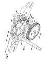
- FIG. 1 schematically shows a perspective view of a transmission.
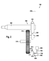
- FIG. 2 schematically shows a plan view of a transmission.
- FIG. 1 shows in a perspective view schematically a transmission 100.
- the transmission 100 may for example serve as a transmission in a windshield wiper drive, for example in a drive of a rear window wiper.
- the transmission 100 has a gear cover 200.
- the gear cover 200 may be made of metal, plastic or other suitable material.
- the transmission 100 further comprises a transfer gear 300.
- the transfer gear 300 has a gear 310 which can be driven by a motor, not shown.
- the gear 310 may be a spur gear, a bevel gear, a helical gear, a crown wheel, a worm wheel or other suitable gear.
- the gear 310 may be rotated by a motor, not shown, about a gear axis 315 of the gear 310.
- the gear 310 with other, not shown, gears are in communication.
- the transfer gear 300 further includes a bearing pin 400, a push rod 320, two guide ribs 330, a pinion 340, and a wiper shaft 500.
- the transfer gear 300 may further include other gears.
- FIG. 2 shows a schematic plan view of the transmission 100.
- the bearing pin 400 is perpendicular to a gear cover 200 facing side of the gear 310 eccentrically with respect to the gear axis 315 attached.
- the bearing pin 400 thus has the gear 310 in the direction of the gear cover 200.
- the bearing pin 400 is pivotally connected to the push rod 320.
- the push rod 320 is pivotally connected to the guide ribs 330 at an attachment point.
- only one guide bar 330 may be present.
- the push rod 320 includes a toothed segment that meshes with the pinion 340.
- the pinion 340 is rotationally connected to the wiper shaft 500.
- the pinion 340 is set in a pendulum rotation about the axis of the wiper shaft 500. Due to the rotationally fixed connection between the pinion 340 and the wiper shaft 500, the oscillating movement of the pinion 340 is transmitted to the wiper shaft 500, so that this also oscillates about the axis of the wiper shaft 500.
- the arrangement of the transfer gear 300, a pendulum rotational movement of the wiper shaft 500 can be achieved by 180 °, for example.
- the wiper shaft 500 is connected to one in the FIGS. 1 and 2 Wiper arm, not shown, which is driven by the oscillating movement of the wiper shaft 500 and serves to clean a disc, for example, a motor vehicle.
- the wiper arm connected to the wiper shaft 500 may have a parking position. As long as the wiper arm's wiping service is not required, the wiper arm is held in the parking position.
- the parking position corresponds to a fixed angle of rotation of the wiper shaft 500, which in turn corresponds to a predetermined angular position of the gear 310.
- the motor 310 driving the motor In order to bring the wiper arm in the parking position, the motor 310 driving the motor must therefore be switched off exactly when the gear 310 is in the parking position associated angular position.
- the gear cover 200 has a first electrical contact surface 650 and a second electrical contact surface 750.
- the first electrical contact surface 650 and the second electrical contact surface 750 are, as in FIG FIG. 1 shown schematically, arranged on a gear 310 facing surface of the gear cover 200.
- the first electrical contact surface 650 is connected to a first conductor track 600.
- the second electrical contact surface 750 is connected to a second conductor track 700.
- the first interconnect 600 and the second interconnect 700 may be embodied as interconnects on a printed circuit board. However, the first interconnect 600 and the second interconnect 700 may also be designed as cables or another type of interconnects.
- the first interconnect 600 and the second interconnect 700 are connected to an evaluation electronics 800, which may also be arranged on the transmission cover 200, for example. If the first interconnect 600 and the second interconnect 700 are embodied as interconnects of a printed circuit board, then the evaluation electronics 800 may be provided on the same circuit board.
- the first contact surface 650 is electrically conductively connected to a pushbutton 670.
- the button 670 may be formed, for example, as a bending or leaf spring.
- the push-button 670 has a contact side 672, which produces an electrically conductive connection to the second contact surface 750 when the push-button 670 is actuated and thereby electrically shorting the first contact surface 650 and the second contact surface 750.
- the pushbutton 670 is designed such that when the pushbutton 670 is not actuated there is no electrical connection between the first electrical contact surface 650 and the second contact surface 750.
- the button 670 also has an operating side 671, via which the button 670 can be actuated.
- the gear 310 has on its the gear cover 200 side facing an elevation 311, which may be formed, for example, as a cam.
- the elevation 311 is arranged on the toothed wheel 310 such that the elevation 311 actuates the operating side 671 of the probe 670 in a predefined angular position of the toothed wheel 310.
- the first contact surface 650 and the second contact surface 750 are electrically short-circuited in a predetermined angular position of the gear 310, which can be detected by means of the evaluation electronics 800.
- the first contact surface 650 and the second contact surface 750 are arranged on the gear cover 200 such that the button 670 is actuated by the elevation 311 of the gear 310 just when the gear 310 is in the angular position in which the connected to the wiper shaft 500 Wiper arm is in parking position. If the windshield wiper system is to be switched off, the electronic evaluation unit 800 ensures that the motor driving the gear 310 continues to run until the first contact surface 650 and the second contact surface 750 are short-circuited by the pushbutton 670. At this moment, the evaluation electronics 800 switches off the motor driving the gear 310. The wiper arm connected to the wiper shaft 500 is then in the parking position. The angular position of the toothed wheel 310 associated with the parking position of the wiper arm connected to the wiper shaft 500 can be adjusted via the position of the first contact surface 650 and the second contact surface 750 on the gear cover 200.
Landscapes
- Engineering & Computer Science (AREA)
- Mechanical Engineering (AREA)
- General Engineering & Computer Science (AREA)
- Connection Of Motors, Electrical Generators, Mechanical Devices, And The Like (AREA)
- Gear Transmission (AREA)
- Mechanisms For Operating Contacts (AREA)
Abstract
Description
- Die Erfindung betrifft ein Getriebe, insbesondere ein Getriebe für einen Scheibenwischerantrieb, sowie einen Scheibenwischerantrieb mit einem Motor und einem Getriebe.
- Im Stand der Technik sind zahlreiche Scheibenwischerantriebe mit Getriebe bekannt. Sogenannte Rundläufer-Scheibenwischerantriebe weisen ein Zahnrad auf, das eine kontinuierliche Rotationsbewegung ausführt und über ein Umsetzgetriebe eine Wischerwelle in eine pendelnde Bewegung versetzt. Zur Erkennung einer Parkposition des Zahnrads ist es bekannt, das Zahnrad mit einer elektrisch leitfähigen Kontaktbahn zu versehen. Zwei mit einem Gehäuse des Scheibenwischerantriebs verbundene Kontaktfedern bilden Schleifkontakte mit der leitfähigen Kontaktbahn. In einer festgelegten Parkposition des Zahnrads schließt die Kontaktbahn die beiden Kontaktfedern kurz, was mittels einer mit den Kontaktfedern verbundenen Auswertelektronik erkannt wird.
- Die Aufgabe der Erfindung besteht darin, ein verbessertes Getriebe bereitzustellen. Diese Aufgabe wird durch ein Getriebe gemäß Anspruch 1 gelöst. Es ist weiter Aufgabe der Erfindung, einen verbesserten Scheibenwischerantrieb bereitzustellen. Diese Aufgabe wird durch einen Scheibenwischerantrieb gemäß Anspruch 7 gelöst. Bevorzugte Weiterbildungen sind in den abhängigen Ansprüchen angegeben.
- Ein erfindungsgemäßes Getriebe umfasst einen Getriebedeckel und ein drehbares Zahnrad, wobei eine in Richtung des Zahnrads weisende Seite des Getriebedeckels eine erste elektrische Kontaktfläche und eine zweite elektrische Kontaktfläche aufweist. Dabei ist die erste elektrische Kontaktfläche mit einem Taster verbunden, der bei Betätigung die erste elektrische Kontaktfläche und die zweite elektrische Kontaktfläche kurzschließt. Außerdem weist eine in Richtung des Getriebedeckels weisende Seite des Zahnrads eine Erhöhung auf. Der Taster und die Erhöhung sind so ausgebildet, dass die Erhöhung den Taster in einer vorgegebenen Stellung des Zahnrads betätigt. Vorteilhafterweise benötigt dieses Getriebe keine Kontaktbahn auf dem Zahnrad und nur eine Kontaktfeder. Durch die Teilereduzierung ergibt sich eine Kostenersparnis. Die geringere Anzahl benötigter Bauteile reduziert außerdem den Montageaufwand und verkürzt die Toleranzkette, was eine präzisere Erkennung einer Stellung des Zahnrads erlaubt.
- Zweckmäßigerweise ist der Taster als Biegefeder ausgebildet.
- Ebenfalls ist es zweckmäßig, die Erhöhung als Nocken auszubilden.
- In einer bevorzugten Ausführungsform sind die erste und die zweite Kontaktfläche mit einer Auswertelektronik verbunden, die dazu ausgebildet ist, einen elektrischen Kurzschluss zwischen der ersten und der zweiten Kontaktfläche zu erkennen.
- Bevorzugt betätigt die Erhöhung den Taster, wenn sich das Zahnrad in einer Parkstellung befindet.
- In einer Ausgestaltung der Erfindung ist das Getriebe zum Antrieb eines Scheibenwischers ausgebildet.
- Ein erfindungsgemäßer Scheibenwischerantrieb umfasst einen Motor und ein erfindungsgemäßes Getriebe.
-
Figur 1 zeigt schematisch eine perspektivische Ansicht eines Getriebes. -
Figur 2 zeigt schematisch eine Aufsicht auf ein Getriebe. -
Figur 1 zeigt in einer perspektivischen Darstellung schematisch ein Getriebe 100. Das Getriebe 100 kann beispielsweise als Getriebe in einem Scheibenwischerantrieb, beispielsweise in einem Antrieb eines Heckscheibenwischers dienen. - Das Getriebe 100 weist einen Getriebedeckel 200 auf. Der Getriebedeckel 200 kann aus Metall, Kunststoff oder einem anderen geeigneten Werkstoff gefertigt sein. Das Getriebe 100 umfasst weiter ein Umsetzgetriebe 300. Das Umsetzgetriebe 300 weist ein Zahnrad 310 auf, das von einem nicht dargestellten Motor angetrieben werden kann. Das Zahnrad 310 kann ein Stirnrad, ein Kegelrad, ein Schraubenrad, ein Kronrad, ein Schneckenrad oder ein anderes geeignetes Zahnrad sein. Das Zahnrad 310 kann durch den nicht dargestellten Motor in Rotation um eine Zahnradachse 315 des Zahnrads 310 versetzt werden. Hierfür kann das Zahnrad 310 mit weiteren, nicht dargestellten, Zahnrädern in Verbindung stehen. Das Umsetzgetriebe 300 umfasst außerdem einen Lagerbolzen 400, eine Schubstange 320, zwei Führungsstege 330, einen Ritzel 340 und eine Wischerwelle 500. Das Umsetzgetriebe 300 kann außerdem weitere Zahnräder umfassen.
-
Figur 2 zeigt eine schematische Aufsicht auf das Getriebe 100. Der Lagerbolzen 400 ist senkrecht auf einer dem Getriebedeckel 200 zugewandten Seite des Zahnrads 310 exzentrisch in Bezug auf die Zahnradachse 315 angebracht. Der Lagerbolzen 400 weist also von dem Zahnrad 310 in Richtung des Getriebedeckels 200. Der Lagerbolzen 400 ist gelenkig mit der Schubstange 320 verbunden. Durch eine Drehung des Zahnrads 310 um die Zahnradachse 315 wird die Schubstange 320 über den Lagerbolzen 400 in eine Hub-Pendelbewegung versetzt. Die Schubstange 320 ist an einem Befestigungspunkt gelenkig mit den Führungsstegen 330 verbunden. Alternativ kann auch lediglich ein Führungssteg 330 vorhanden sein. - Die Schubstange 320 umfasst ein Zahnsegment, das mit dem Ritzel 340 im Eingriff steht. Das Ritzel 340 ist verdrehfest mit der Wischerwelle 500 verbunden. Durch die Hub-Pendelbewegung der Schubstange 320 wird das Ritzel 340 in eine Pendeldrehung um die Achse der Wischerwelle 500 versetzt. Durch die verdrehfeste Verbindung zwischen Ritzel 340 und Wischerwelle 500 wird die pendelnde Bewegung des Ritzels 340 auf die Wischerwelle 500 übertragen, so dass diese ebenfalls um die Achse der Wischerwelle 500 pendelt. Durch die Anordnung des Umsetzgetriebes 300 kann eine pendelnde Drehbewegung der Wischerwelle 500 um beispielsweise 180° erreicht werden. Die Wischerwelle 500 ist mit einem in den
Figuren 1 und2 nicht dargestellten Wischarm verbunden, der durch die Pendelbewegung der Wischerwelle 500 angetrieben wird und zum Reinigen einer Scheibe beispielsweise eines Kraftfahrzeugs dient. - Der mit der Wischerwelle 500 verbundene Wischarm kann eine Parkposition aufweisen. Solange der Wischdienst des Wischarms nicht benötigt wird, wird der Wischarm in der Parkposition gehalten. Die Parkposition entspricht einem festgelegten Drehwinkel der Wischerwelle 500, der wiederum mit einer festgelegten Winkelstellung des Zahnrads 310 korrespondiert. Um den Wischerarm in die Parkposition zu bringen, muss der das Zahnrad 310 antreibende Motor also genau dann abgeschaltet werden, wenn sich das Zahnrad 310 in der der Parkposition zugeordneten Winkelstellung befindet.
- Hierzu weist der Getriebedeckel 200 eine erste elektrische Kontaktfläche 650 und eine zweite elektrische Kontaktfläche 750 auf. Die erste elektrische Kontaktfläche 650 und die zweite elektrische Kontaktfläche 750 sind, wie in
Figur 1 schematisch dargestellt, an einer dem Zahnrad 310 zugewandten Oberfläche des Getriebedeckels 200 angeordnet. Die erste elek-trische Kontaktfläche 650 ist mit einer ersten Leiterbahn 600 verbunden. Die zweite elektrische Kontaktfläche 750 ist mit einer zweiten Leiterbahn 700 verbunden. Die erste Leiterbahn 600 und die zweite Leiterbahn 700 können als Leiterbahnen auf einer Leiterplatte ausgeführt sein. Die erste Leiterbahn 600 und die zweite Leiterbahn 700 können aber auch als Kabel oder eine andere Art von Leiterbahnen ausgeführt sein. Die erste Leiterbahn 600 und die zweite Leiterbahn 700 sind mit einer Auswertelektronik 800 verbunden, die beispielsweise ebenfalls am Getriebedeckel 200 angeordnet sein kann. Falls die erste Leiterbahn 600 und die zweite Leiterbahn 700 als Leiterbahnen einer Leiterplatte ausgeführt sind, so kann die Auswertelektronik 800 auf derselben Leiterplatte vorgesehen sein. - Die erste Kontaktfläche 650 ist elektrisch leitfähig mit einem Taster 670 verbunden. Der Taster 670 kann beispielsweise als Biege- oder Blattfeder ausgebildet sein. Der Taster 670 weist eine Kontaktseite 672 auf, die bei Betätigung des Tasters 670 eine elektrisch leitfähige Verbindung zur zweiten Kontaktfläche 750 herstellt und dadurch die erste Kontaktfläche 650 und die zweite Kontaktfläche 750 elektrisch kurzschließt. Der Taster 670 ist so ausgebildet, dass bei unbetätigtem Taster 670 keine elektrische Verbindung zwischen der ersten elektrischen Kontaktfläche 650 und der zweiten Kontaktfläche 750 besteht. Der Taster 670 weist außerdem eine Bedienseite 671 auf, über die der Taster 670 betätigt werden kann.
- Das Zahnrad 310 weist auf seiner dem Getriebedeckel 200 zugewandten Seite eine Erhöhung 311 auf, die beispielsweise als Nocken ausgebildet sein kann. Die Erhöhung 311 ist derart auf dem Zahnrad 310 angeordnet, dass die Erhöhung 311 in einer vorgegebenen Winkelstellung des Zahnrads 310 die Bedienseite 671 des Tasters 670 betätigt. Dadurch werden die erste Kontaktfläche 650 und die zweite Kontaktfläche 750 in einer vorgegebenen Winkelstellung des Zahnrads 310 elektrisch kurzgeschlossen, was mittels der Auswertelektronik 800 erfasst werden kann. In anderen Winkelstellungen des Zahnrads 310 besteht kein elektrischer Kontakt zwischen der ersten Kontaktfläche 650 und der zweiten Kontaktfläche 750.
- Die erste Kontaktfläche 650 und die zweite Kontaktfläche 750 sind derart am Getriebedeckel 200 angeordnet, dass der Taster 670 genau dann durch die Erhöhung 311 des Zahnrads 310 betätigt wird, wenn sich das Zahnrad 310 in derjenigen Winkelstellung befindet, in der der mit der Wischerwelle 500 verbundene Wischarm sich in der Parkposition befindet. Soll sich Scheibenwischanlage abgeschaltet werden, so sorgt die Auswertelektronik 800 dafür, dass der das Zahnrad 310 antreibende Motor so lange weiterläuft, bis die erste Kontaktfläche 650 und die zweite Kontaktfläche 750 durch den Taster 670 kurzgeschlossen werden. In diesem Moment schaltet die Auswertelektronik 800 den das Zahnrad 310 antreibenden Motor ab. Der mit der Wischerwelle 500 verbundene Wischarm befindet sich dann in der Parkposition. Die der Parkposition des mit der Wischerwelle 500 verbundenen Wischarms zugeordnete Winkelstellung des Zahnrads 310 kann über die Lage der ersten Kontaktfläche 650 und der zweiten Kontaktfläche 750 auf dem Getriebedeckel 200 angepasst werden.
Claims (7)
- Getriebe (100)
mit einem Getriebedeckel (200) und einem drehbaren Zahnrad (310),
wobei eine in Richtung des Zahnrads (310) weisende Seite des Getriebedeckels (200) eine erste elektrische Kontaktfläche (650) und eine zweite elektrische Kontaktfläche (750) aufweist,
dadurch gekennzeichnet, dass
die erste elektrische Kontaktfläche (650) mit einem Taster (670) verbunden ist, der bei Betätigung die erste elektrische Kontaktfläche (650) und die zweite elektrische Kontaktfläche (750) kurzschließt,
eine in Richtung des Getriebedeckels (200) weisende Seite des Zahnrads (300) eine Erhöhung (311) aufweist,
und der Taster (670) und die Erhöhung (311) so ausgebildet sind, dass die Erhöhung (311) den Taster (670) in einer vorgegebenen Stellung des Zahnrads (310) betätigt. - Getriebe (100) nach Anspruch 1,
wobei der Taster (670) als Biegefeder ausgebildet ist. - Getriebe (100) nach einem der vorhergehenden Ansprüche,
wobei die Erhöhung (311) als Nocken ausgebildet ist. - Getriebe (100) nach einem der vorhergehenden Ansprüche,
wobei die erste und die zweite Kontaktfläche (650, 750) mit einer Auswertelektronik (800) verbunden sind, die dazu ausgebildet ist, einen elektrischen Kurzschluss zwischen der ersten und der zweiten Kontaktfläche (650, 750) zu erkennen. - Getriebe (100) nach einem der vorhergehenden Ansprüche,
wobei die Erhöhung (311) den Taster (670) betätigt, wenn sich das Zahnrad (310) in einer Parkstellung befindet. - Getriebe (100) nach einem der vorhergehenden Ansprüche,
wobei das Getriebe (100) zum Antrieb eines Scheibenwischers ausgebildet ist. - Scheibenwischerantrieb
mit einem Motor
und einem Getriebe (100) nach einem der Ansprüche 1 bis 6.
Applications Claiming Priority (1)
| Application Number | Priority Date | Filing Date | Title |
|---|---|---|---|
| DE200810043612 DE102008043612A1 (de) | 2008-11-10 | 2008-11-10 | Getriebe |
Publications (2)
| Publication Number | Publication Date |
|---|---|
| EP2184515A2 true EP2184515A2 (de) | 2010-05-12 |
| EP2184515A3 EP2184515A3 (de) | 2013-06-12 |
Family
ID=41396082
Family Applications (1)
| Application Number | Title | Priority Date | Filing Date |
|---|---|---|---|
| EP09170969.1A Withdrawn EP2184515A3 (de) | 2008-11-10 | 2009-09-22 | Getriebe |
Country Status (3)
| Country | Link |
|---|---|
| EP (1) | EP2184515A3 (de) |
| CN (1) | CN101734230B (de) |
| DE (1) | DE102008043612A1 (de) |
Cited By (2)
| Publication number | Priority date | Publication date | Assignee | Title |
|---|---|---|---|---|
| WO2013050534A1 (fr) * | 2011-10-07 | 2013-04-11 | Valeo Systèmes d'Essuyage | Commutateur électrique pour système d'entraînement de balai d'essuyage et système d'entraînement correspondant |
| EP2746116A3 (de) * | 2012-12-20 | 2018-05-02 | Robert Bosch Gmbh | Antriebseinrichtung mit positionsabhängiger Schalteinrichtung für Signalauswertung auf ein abfallendes Signal |
Families Citing this family (1)
| Publication number | Priority date | Publication date | Assignee | Title |
|---|---|---|---|---|
| DE102022110700A1 (de) | 2022-05-02 | 2023-11-02 | Valeo Systèmes d'Éssuyage SAS | Getriebe und Scheibenwischermotor mit einem Getriebe |
Citations (1)
| Publication number | Priority date | Publication date | Assignee | Title |
|---|---|---|---|---|
| DE19609973A1 (de) | 1996-03-14 | 1997-09-18 | Teves Gmbh Alfred | Antriebsvorrichtung für Scheibenwischer mit einem Parkstellungsschalter |
Family Cites Families (6)
| Publication number | Priority date | Publication date | Assignee | Title |
|---|---|---|---|---|
| JPH0825432B2 (ja) * | 1986-09-24 | 1996-03-13 | 日産自動車株式会社 | 車両用ワイパの払拭角度切換装置 |
| JP2590581Y2 (ja) * | 1992-05-11 | 1999-02-17 | 株式会社ミツバ | ワイパ駆動装置 |
| DE10014735A1 (de) * | 2000-03-24 | 2001-10-11 | Bosch Gmbh Robert | Elektromotor insbesondere Wischermotor zum Wischen einer Scheibe eines Kraftfahrzeugs |
| DE102005028813A1 (de) * | 2005-06-22 | 2007-01-04 | Robert Bosch Gmbh | Antrieb für eine Scheibenwischanlage eines Fahrzeugs |
| DE102005062778A1 (de) * | 2005-12-28 | 2007-07-05 | Robert Bosch Gmbh | Scheibenwischvorrichtung |
| CN100411922C (zh) * | 2006-08-29 | 2008-08-20 | 林江分 | 车辆后视镜雨刷结构 |
-
2008
- 2008-11-10 DE DE200810043612 patent/DE102008043612A1/de not_active Withdrawn
-
2009
- 2009-09-22 EP EP09170969.1A patent/EP2184515A3/de not_active Withdrawn
- 2009-11-09 CN CN200910221047.XA patent/CN101734230B/zh not_active Expired - Fee Related
Patent Citations (1)
| Publication number | Priority date | Publication date | Assignee | Title |
|---|---|---|---|---|
| DE19609973A1 (de) | 1996-03-14 | 1997-09-18 | Teves Gmbh Alfred | Antriebsvorrichtung für Scheibenwischer mit einem Parkstellungsschalter |
Cited By (3)
| Publication number | Priority date | Publication date | Assignee | Title |
|---|---|---|---|---|
| WO2013050534A1 (fr) * | 2011-10-07 | 2013-04-11 | Valeo Systèmes d'Essuyage | Commutateur électrique pour système d'entraînement de balai d'essuyage et système d'entraînement correspondant |
| FR2981031A1 (fr) * | 2011-10-07 | 2013-04-12 | Valeo Systemes Dessuyage | Commutateur electrique pour systeme d'entrainement de balai d'essuyage et systeme d'entrainement correspondant |
| EP2746116A3 (de) * | 2012-12-20 | 2018-05-02 | Robert Bosch Gmbh | Antriebseinrichtung mit positionsabhängiger Schalteinrichtung für Signalauswertung auf ein abfallendes Signal |
Also Published As
| Publication number | Publication date |
|---|---|
| EP2184515A3 (de) | 2013-06-12 |
| DE102008043612A1 (de) | 2010-05-12 |
| CN101734230B (zh) | 2014-10-22 |
| CN101734230A (zh) | 2010-06-16 |
Similar Documents
| Publication | Publication Date | Title |
|---|---|---|
| DE3316653C2 (de) | ||
| EP1917167B1 (de) | Elektromotorischer hilfsantrieb für fahrzeuge | |
| DE4323946C1 (de) | Antriebsvorrichtung für ein verstellbares Fahrzeugteil | |
| EP1185443A1 (de) | Elektromotor insbesondere wischermotor zum wischen einer scheibe eines kraftfahrzeugs | |
| DE10339316A1 (de) | Antriebsvorrichtung für Scheibenwischer mit einem Parkstellungsschalter | |
| DE102008002724A1 (de) | Verfahren zur Erkennung des Drehwinkels und einer Reversierposition einer Getriebe-Antriebseinheit | |
| DE10014073B4 (de) | Sicherheitsgerät für motorbetriebene Fenster | |
| EP2346724B1 (de) | Getriebe | |
| DE102015122095A1 (de) | Anschlusseinheit für einen Wischermotor für Scheibenwischanlagen und Wischermotor | |
| DE102008043612A1 (de) | Getriebe | |
| EP1713670A1 (de) | Verfahren zum einstellen eines wischwinkels | |
| DE10348914B4 (de) | Vorrichtung zum Messen des Drehwinkels eines Drehkörpers | |
| EP1768009B1 (de) | Drehsteller | |
| EP2946966A1 (de) | Sitz für einen fahrzeugführer einer baumaschine, baumaschine, sowie verfahren zum verstellen eines sitzes | |
| EP1876055A1 (de) | Lenkstockschalter | |
| WO2020120468A1 (de) | Sensoreinheit mit wenigstens einem aus einer leiterplatte gebildeten zahnrad | |
| DE19926576C2 (de) | Bedieneinrichtung zur manuellen Eingabe von Steuersignalen an eine Steuereinheit | |
| EP3441262B1 (de) | Lenksäulenmodul für ein kraftfahrzeug mit einer flügelartigen zahnstange an einem lenkstockhebel, sowie kraftfahrzeug mit einem derartigen lenksäulenmodul | |
| DE102005028813A1 (de) | Antrieb für eine Scheibenwischanlage eines Fahrzeugs | |
| DE4431152C2 (de) | Baugruppe für den Antrieb und die Steuerung eines Scheibenwischers in Kraftfahrzeugen | |
| DE102012223894A1 (de) | Antriebseinrichtung mit positionsabhängiger Schalteinrichtung für Signalauswertung auf ein abfallendes Signal | |
| DE102012017123B4 (de) | Signalgeber, insbesondere elektrischer Drehschalter | |
| DE102013212280A1 (de) | Antriebseinrichtung für eine Scheibenwischvorrichtung | |
| DE102009029492A1 (de) | Antriebsvorrichtung für Scheibenwischer mit einer Positionsermittlungseinrichtung | |
| WO2008068099A1 (de) | Antriebsvorrichtung von fahrzeugaggregaten |
Legal Events
| Date | Code | Title | Description |
|---|---|---|---|
| PUAI | Public reference made under article 153(3) epc to a published international application that has entered the european phase |
Free format text: ORIGINAL CODE: 0009012 |
|
| AK | Designated contracting states |
Kind code of ref document: A2 Designated state(s): AT BE BG CH CY CZ DE DK EE ES FI FR GB GR HR HU IE IS IT LI LT LU LV MC MK MT NL NO PL PT RO SE SI SK SM TR |
|
| AX | Request for extension of the european patent |
Extension state: AL BA RS |
|
| PUAL | Search report despatched |
Free format text: ORIGINAL CODE: 0009013 |
|
| AK | Designated contracting states |
Kind code of ref document: A3 Designated state(s): AT BE BG CH CY CZ DE DK EE ES FI FR GB GR HR HU IE IS IT LI LT LU LV MC MK MT NL NO PL PT RO SE SI SK SM TR |
|
| AX | Request for extension of the european patent |
Extension state: AL BA RS |
|
| RIC1 | Information provided on ipc code assigned before grant |
Ipc: B60S 1/26 20060101ALI20130507BHEP Ipc: F16H 57/02 20120101AFI20130507BHEP |
|
| 17P | Request for examination filed |
Effective date: 20131212 |
|
| RAX | Requested extension states of the european patent have changed |
Extension state: RS Payment date: 20131212 Extension state: BA Payment date: 20131212 Extension state: AL Payment date: 20131212 |
|
| RBV | Designated contracting states (corrected) |
Designated state(s): AT BE BG CH CY CZ DE DK EE ES FI FR GB GR HR HU IE IS IT LI LT LU LV MC MK MT NL NO PL PT RO SE SI SK SM TR |
|
| 17Q | First examination report despatched |
Effective date: 20140514 |
|
| STAA | Information on the status of an ep patent application or granted ep patent |
Free format text: STATUS: THE APPLICATION IS DEEMED TO BE WITHDRAWN |
|
| 18D | Application deemed to be withdrawn |
Effective date: 20170401 |