EP2184448A2 - Dispositif de soutirage d'air - Google Patents
Dispositif de soutirage d'air Download PDFInfo
- Publication number
- EP2184448A2 EP2184448A2 EP09252068A EP09252068A EP2184448A2 EP 2184448 A2 EP2184448 A2 EP 2184448A2 EP 09252068 A EP09252068 A EP 09252068A EP 09252068 A EP09252068 A EP 09252068A EP 2184448 A2 EP2184448 A2 EP 2184448A2
- Authority
- EP
- European Patent Office
- Prior art keywords
- flow
- apertures
- cells
- inlet
- aperture
- Prior art date
- Legal status (The legal status is an assumption and is not a legal conclusion. Google has not performed a legal analysis and makes no representation as to the accuracy of the status listed.)
- Granted
Links
- 230000000740 bleeding effect Effects 0.000 title 1
- 238000005192 partition Methods 0.000 claims abstract description 32
- 230000008602 contraction Effects 0.000 claims abstract description 6
- 210000004027 cell Anatomy 0.000 claims description 80
- 210000002421 cell wall Anatomy 0.000 claims description 13
- 238000000034 method Methods 0.000 claims description 10
- 238000003491 array Methods 0.000 claims description 4
- 210000003850 cellular structure Anatomy 0.000 claims description 2
- 235000002566 Capsicum Nutrition 0.000 description 9
- 239000006002 Pepper Substances 0.000 description 9
- 241000722363 Piper Species 0.000 description 9
- 235000016761 Piper aduncum Nutrition 0.000 description 9
- 235000017804 Piper guineense Nutrition 0.000 description 9
- 235000008184 Piper nigrum Nutrition 0.000 description 9
- 238000000429 assembly Methods 0.000 description 4
- 230000000712 assembly Effects 0.000 description 4
- 238000002156 mixing Methods 0.000 description 4
- 238000002485 combustion reaction Methods 0.000 description 3
- 238000004519 manufacturing process Methods 0.000 description 3
- 230000001141 propulsive effect Effects 0.000 description 3
- 238000011144 upstream manufacturing Methods 0.000 description 3
- 238000001465 metallisation Methods 0.000 description 2
- 230000001737 promoting effect Effects 0.000 description 2
- 238000000110 selective laser sintering Methods 0.000 description 2
- 230000001052 transient effect Effects 0.000 description 2
- 230000001133 acceleration Effects 0.000 description 1
- 238000005452 bending Methods 0.000 description 1
- 238000004891 communication Methods 0.000 description 1
- 230000006835 compression Effects 0.000 description 1
- 238000007906 compression Methods 0.000 description 1
- 238000000151 deposition Methods 0.000 description 1
- 230000008021 deposition Effects 0.000 description 1
- 230000000694 effects Effects 0.000 description 1
- 239000000446 fuel Substances 0.000 description 1
- 238000003698 laser cutting Methods 0.000 description 1
- 238000011068 loading method Methods 0.000 description 1
- 239000002184 metal Substances 0.000 description 1
- 239000000203 mixture Substances 0.000 description 1
- 239000000843 powder Substances 0.000 description 1
- 230000035939 shock Effects 0.000 description 1
Images


Classifications
-
- F—MECHANICAL ENGINEERING; LIGHTING; HEATING; WEAPONS; BLASTING
- F01—MACHINES OR ENGINES IN GENERAL; ENGINE PLANTS IN GENERAL; STEAM ENGINES
- F01D—NON-POSITIVE DISPLACEMENT MACHINES OR ENGINES, e.g. STEAM TURBINES
- F01D17/00—Regulating or controlling by varying flow
- F01D17/10—Final actuators
- F01D17/105—Final actuators by passing part of the fluid
-
- F—MECHANICAL ENGINEERING; LIGHTING; HEATING; WEAPONS; BLASTING
- F02—COMBUSTION ENGINES; HOT-GAS OR COMBUSTION-PRODUCT ENGINE PLANTS
- F02C—GAS-TURBINE PLANTS; AIR INTAKES FOR JET-PROPULSION PLANTS; CONTROLLING FUEL SUPPLY IN AIR-BREATHING JET-PROPULSION PLANTS
- F02C7/00—Features, components parts, details or accessories, not provided for in, or of interest apart form groups F02C1/00 - F02C6/00; Air intakes for jet-propulsion plants
- F02C7/24—Heat or noise insulation
-
- F—MECHANICAL ENGINEERING; LIGHTING; HEATING; WEAPONS; BLASTING
- F02—COMBUSTION ENGINES; HOT-GAS OR COMBUSTION-PRODUCT ENGINE PLANTS
- F02C—GAS-TURBINE PLANTS; AIR INTAKES FOR JET-PROPULSION PLANTS; CONTROLLING FUEL SUPPLY IN AIR-BREATHING JET-PROPULSION PLANTS
- F02C9/00—Controlling gas-turbine plants; Controlling fuel supply in air- breathing jet-propulsion plants
- F02C9/16—Control of working fluid flow
- F02C9/18—Control of working fluid flow by bleeding, bypassing or acting on variable working fluid interconnections between turbines or compressors or their stages
-
- F—MECHANICAL ENGINEERING; LIGHTING; HEATING; WEAPONS; BLASTING
- F02—COMBUSTION ENGINES; HOT-GAS OR COMBUSTION-PRODUCT ENGINE PLANTS
- F02K—JET-PROPULSION PLANTS
- F02K3/00—Plants including a gas turbine driving a compressor or a ducted fan
- F02K3/02—Plants including a gas turbine driving a compressor or a ducted fan in which part of the working fluid by-passes the turbine and combustion chamber
- F02K3/04—Plants including a gas turbine driving a compressor or a ducted fan in which part of the working fluid by-passes the turbine and combustion chamber the plant including ducted fans, i.e. fans with high volume, low pressure outputs, for augmenting the jet thrust, e.g. of double-flow type
- F02K3/075—Plants including a gas turbine driving a compressor or a ducted fan in which part of the working fluid by-passes the turbine and combustion chamber the plant including ducted fans, i.e. fans with high volume, low pressure outputs, for augmenting the jet thrust, e.g. of double-flow type controlling flow ratio between flows
-
- B—PERFORMING OPERATIONS; TRANSPORTING
- B33—ADDITIVE MANUFACTURING TECHNOLOGY
- B33Y—ADDITIVE MANUFACTURING, i.e. MANUFACTURING OF THREE-DIMENSIONAL [3-D] OBJECTS BY ADDITIVE DEPOSITION, ADDITIVE AGGLOMERATION OR ADDITIVE LAYERING, e.g. BY 3-D PRINTING, STEREOLITHOGRAPHY OR SELECTIVE LASER SINTERING
- B33Y80/00—Products made by additive manufacturing
-
- F—MECHANICAL ENGINEERING; LIGHTING; HEATING; WEAPONS; BLASTING
- F05—INDEXING SCHEMES RELATING TO ENGINES OR PUMPS IN VARIOUS SUBCLASSES OF CLASSES F01-F04
- F05D—INDEXING SCHEME FOR ASPECTS RELATING TO NON-POSITIVE-DISPLACEMENT MACHINES OR ENGINES, GAS-TURBINES OR JET-PROPULSION PLANTS
- F05D2210/00—Working fluids
- F05D2210/40—Flow geometry or direction
- F05D2210/43—Radial inlet and axial outlet
-
- Y—GENERAL TAGGING OF NEW TECHNOLOGICAL DEVELOPMENTS; GENERAL TAGGING OF CROSS-SECTIONAL TECHNOLOGIES SPANNING OVER SEVERAL SECTIONS OF THE IPC; TECHNICAL SUBJECTS COVERED BY FORMER USPC CROSS-REFERENCE ART COLLECTIONS [XRACs] AND DIGESTS
- Y02—TECHNOLOGIES OR APPLICATIONS FOR MITIGATION OR ADAPTATION AGAINST CLIMATE CHANGE
- Y02T—CLIMATE CHANGE MITIGATION TECHNOLOGIES RELATED TO TRANSPORTATION
- Y02T50/00—Aeronautics or air transport
- Y02T50/60—Efficient propulsion technologies, e.g. for aircraft
Definitions
- This invention relates to a noise reduction device, and is particularly, although not exclusively, concerned with such a device for use with a bleed valve in a gas turbine engine to release compressed air from a compressor stage to a bypass duct of the engine.
- a gas turbine engine When a gas turbine engine is operating under transient conditions, for example when decelerating, it may be necessary to bleed air at high pressure from the core gas flow through the engine. Such air may be transferred to a bypass flow within the engine. Bleed valves are provided to control this transfer of air.
- the flow of bleed air from the core gas flow into the bypass flow takes place over a substantial pressure drop, and can generate significant noise. It is therefore usual to provide a noise reduction device in, or at the exit of, the flow passage between the core gas flow and the bypass duct.
- a typical measure is to discharge the bleed air into the bypass duct through a perforated plate, sometimes referred to as a "pepper pot" as disclosed, for example, in US2001/0042368 .
- the pepper pot serves to break the single body of air flowing towards the bypass duct into a large number of smaller jets which promote small-scale turbulence and hence quicker mixing with the main flow through the bypass duct.
- Pepper pots In order to avoid a single large pressure drop and sudden expansion from the high pressure core flow to the bypass flow, two or more pepper pots have been used in series, in order to break the single large pressure drop into a series of smaller pressure drops.
- Pepper pots are typically made from thin metallic sheets in which holes are formed, for example by laser cutting, and tend to be expensive. If a series of pepper pots are used downstream of a single bleed valve, the cost is multiplied. Also, pepper pots are subjected to high transient pressure drops, and the shock loadings can cause them to deform or disintegrate.
- a bleed assembly for a gas turbine engine, the assembly comprising a noise reduction device for a flow of gas, the assembly comprising a flow passage, a bleed valve at an inlet to the flow passage and a noise reduction body extending across the flow passage, the noise reduction body having a cellular structure comprising partitions which define a plurality of cells which communicate with one another through inlet and outlet apertures in walls of the cells to provide a plurality of flow paths through the noise reduction body, each cell having at least one of the inlet apertures and at least one of the outlet apertures, which inlet and outlet apertures each cause a contraction of the flow through the noise reduction body followed by sudden expansion of flow emerging into or from the respective cell, the apertures having increasing flow cross-sections in the direction of gas flow.
- the or each inlet aperture of at least one of the cells may have a flow cross-section which is small relative to the flow cross-section through the respective cell, so that the contracted flow issuing from the inlet aperture has space within the cell to undergo rapid expansion.
- the or each inlet aperture of at least one of the cells may be oriented to direct flow issuing from the aperture towards an unapertured region of a wall of the cell.
- the inlet and outlet apertures of at least one of the cells may be disposed so that flow travelling through the cell from the inlet aperture to the outlet aperture changes direction during passage through the cell.
- the or each inlet aperture of the cell may be provided in a cell wall which extends perpendicular to another cell wall in which the or each outlet aperture is disposed.
- the flow direction through the or each inlet aperture differs from that through the or each outlet aperture.
- the inlet and outlet apertures may be disposed in cell walls that are parallel to each other, with the inlet and outlet apertures offset laterally from one another with respect to the flow direction through the apertures.
- Flow directing webs may be situated adjacent at least one of the apertures of at least one of the cells in order to direct flow issuing from the aperture in a desired direction.
- Adjacent cells may communicate with each other through a common one of the apertures, which constitutes the outlet aperture of one of the cells and the inlet aperture of the other cell.
- the apertures may have increasing flow cross-section in the flow direction through the body in order to accommodate increasing volume flow rates as the gas expands through the cells.
- the partitions may be disposed in intersecting arrays to form the cells.
- the partitions in each array may be parallel to each other, and there may be three arrays in an orthogonal configuration. With such an arrangement, the cells each have a generally parallelepiped form.
- the noise reduction body may be manufactured by a stereolithographic process, such as a selective laser sintering process or a laser direct metal deposition process. Such processes enable the manufacture of complex structures, including the partitions and the apertures.
- the present invention also provides a bleed valve assembly for a gas turbine engine, the assembly comprising a noise reduction device as defined above, having a bleed valve at an inlet end of the flow passage.
- the present invention also provides a gas turbine engine having a compressor, a bypass duct, and a bleed valve assembly as defined above, the flow passage extending between the compressor and the bypass duct.
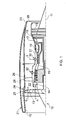
- a ducted fan gas turbine engine generally indicated at 10 has a principal and rotational axis 11.
- the engine 10 comprises, in axial flow series, an air intake 12, a propulsive fan 13, an intermediate pressure compressor 14, a high-pressure compressor 15, combustion equipment 16, a high-pressure turbine 17, an intermediate pressure turbine 18, a low-pressure turbine 19 and a core exhaust nozzle 20.
- a nacelle 21 generally surrounds the engine 10 and defines the intake 12, a bypass duct 22 and an exhaust nozzle 23.
- the gas turbine engine 10 works in the conventional manner so that air entering the intake 11 is accelerated by the fan 13 to produce two air flows: a first airflow A into the intermediate pressure compressor 14 and a second airflow B which passes through the bypass duct 22 to provide propulsive thrust.
- the intermediate pressure compressor 14 compresses the airflow A directed into it before delivering that air to the high pressure compressor 15 where further compression takes place.
- the compressed air exhausted from the high-pressure compressor 15 is directed into the combustion equipment 16 where it is mixed with fuel and the mixture combusted.
- the resultant hot combustion products then expand through, and thereby drive, the high, intermediate and low-pressure turbines 17, 18, 19 before being exhausted through the nozzle 20 to provide additional propulsive thrust.
- the high, intermediate and low-pressure turbines 17, 18, 19 respectively drive the high and intermediate pressure compressors 15, 14 and the fan 13 by suitable interconnecting shafts.
- the fan 13 is circumferentially surrounded by a structural member in the form of a fan casing 24, which is supported by an annular array of outlet guide vanes 28.
- the fan casing 24 comprises a rigid containment casing 25 and attached inwardly thereto is a rear fan casing 26.
- bleed assemblies 30 are provided to release pressure from an upstream part of a compressor 14, 15. Operation of a bleed assembly 30 and engine operability are described in " The Jet Engine” 6th Edition, 2005, Rolls-Royce plc, pages 79-80 , and details of such operation will therefore only be briefly mentioned herein.
- FIG. 2 shows one of the bleed assemblies 30.
- Each bleed assembly 30 comprises an inlet 32, a bleed valve 34, a duct 36 and an outlet 38.
- a noise reduction device 40 is situated at the junction between the duct 36 and the outlet 38.
- the duct 36 and the outlet 38 together define a flow passage 39.
- Parts of core engine airflow A may be diverted through the bleed assembly 30 by opening the bleed valve 34, such that the bleed airflow enters the inlet 32, passes through the bleed valve 34 and is channelled the flow passage 39 defined by the duct 36 and the outlet 38 into the bypass flow B in the bypass duct 22.
- the noise reducing device 40 is provided.
- a baffle 42 is provided at the exit from the bleed valve 34, and the noise reduction device 40 is in the form of a noise reduction body which is a monolithic component, or cassette, which is supported at the junction between the bleed duct 36 and outlet 38 on a partition 44.
- the noise reduction body 40 has an inlet face 68 and an outlet face 70.
- the structure as illustrated in Figure 5 comprises two perpendicular arrays of partitions 50, 52, the partitions 50, 52 in each array being parallel to one another.
- the structure also comprises a further array of partitions (not shown) which lie in planes parallel to the plane of the Figure, so that the overall structure comprises intersecting partitions lying parallel to three orthogonal planes.
- the partitions 50, 52 thus form the walls of cells 54 which, as seen in Figure 5 , have a generally square shape and which consequently, in conjunction with the cell walls constituted by the partitions lying parallel to the plane of the Figure, are of parallelepiped form.
- the partitions 50, 52 are each angled to the general direction of gas flow through the noise reduction body 40, vertically upwards in the Figure.
- Apertures 56, 58, 60 are provided in the partitions 52 and constitute inlet and outlet apertures of the respective cells 54.
- each cell 54 in the lower row shown in Figure 5 comprises an inlet aperture 56 and an outlet aperture 58.
- the outlet aperture 58 of each cell in the lower row serves as the inlet aperture for the adjacent downstream cell in the upper row.
- the apertures 60 constitute the outlet apertures for the cells in the upper row.
- Adjacent each of the apertures 56 and 58 are provided with webs 62 which extend from the respective apertures 56, 58 into the cells 54 of which they form the inlet apertures
- Further webs 64 which can be regarded as extensions of the webs 62, extend in the upstream direction from the apertures 56.
- flow from the valve 34 and the baffle plate 42 in Figure 2 travels along the flow passage 39 and impinges on the lower surface of the noise reduction body 40, and passes through the inlet apertures 56, guided by the webs 64, into the lower row of cells 54 shown in Figure 5 .
- the apertures 56 causes the flow to contract, and to emerge into the respective cells 54 in the form of jets directed, with the assistance of the webs 62, at an unapertured region of the opposite cell wall constituted by one of the partitions 52. Entry of the jet into the respective cell 54 causes it to expand rapidly, so losing pressure, and to lose kinetic energy owing to the impact of the jet against the opposite cell wall.
- inlet apertures 56 and outlet apertures 58 of the cells 54 in the lower row as seen in Figure 5 are laterally offset with respect to one another in the direction of flow through the apertures 56, 58 (as indicated by arrows). The result of this is that gas flowing from the inlet aperture 56 of each cell 54 to the outlet aperture 58 must change direction, so promoting mixing of the jet issuing from the inlet passage 56.
- a similar configuration is present in the cells 54 in the upper row as shown in Figure 5 . Again, flow entering each cell 54 through the respective aperture 58 (which for this purpose becomes an inlet aperture) is directed by the web 62 against the opposite cell wall, and is forced to change direction to emerge from the outlet aperture 60.
- each sudden expansion of the flow as it emerges from the respective apertures 56, 58 results in an increase in the volumetric flow rate through the body 40. Consequently, in order to enable this increased volumetric flow rate, the apertures 58 are larger in flow cross-section than the apertures 56, and the apertures 60 are larger again.
- Figure 5 shows only a small section of the entire body 40. Also, although only two rows of cells 54 are shown in Figure 5 , so that there are two contractions in the flow followed by rapid expansion into the cells 54, and a further contraction and expansion as the flow passes through the apertures 60, it would be possible for the body 40 to have more than two rows of cells, and a greater number of contractions and rapid expansions.
- Figure 6 shows an alternative configuration for the internal structure of the body 40.
- Figure 6 as in Figures 7 and 8 , the same reference numbers have been used as in Figure 5 to designate corresponding features.
- the upper row of cells 54 are somewhat elongated, so that they are rectangular, rather than square, in the view shown in Figure 6 .
- the apertures 56, 58 lacks the webs 62, 64 of the embodiment of Figure 5 .
- alternate apertures 56, 58, 60 in the flow direction are in partitions 50, 52 which are inclined to one another.
- the apertures 58 which provide communication between adjacent cells in the flow direction are in the partitions 50, while the inlet flow to the lower row of cells 54 and the outlet flow from the upper row of cells 54 takes place through the apertures 56, 60 which are disposed in the walls 52. Consequently, flow through the apertures 58 takes place in a direction perpendicular to the flow through the apertures 56 and 60.
- the flow is forced to follow a tortuous path which promotes mixing of the jets emerging from the apertures 56 and 58 into the respective cells 54.
- Figure 7 shows a third embodiment, similar to that of Figure 6 , in which webs 66 project from each aperture 56, 58, 60 in the upstream direction with respect to the normal flow direction indicated by arrows. These webs 66 thus serve initially to guide the flow in the flow passage 39 ( Figure 2 ) into the first cells 54 through the apertures 56. Subsequently, the respective webs 66 at the apertures 58 and 60 serve to create eddies and other turbulence within the cells 54 so promoting mixing of the jets issuing from the apertures 56 and 58.
- Figure 8 shows an embodiment similar in some respects to that of Figure 5 , in that the flow direction through the apertures 56, 58, 60 is all in the same direction. Again, successive apertures 56, 58 and 58, 60 are laterally offset with respect to each other so that the flow needs to change direction within the cells 54 to move from the inlet apertures 56, 58 to the respective outlet apertures 58, 60.
- the inlet apertures 56 for the lower row of cells 54 are provided with webs 62 which extend into the respective cell 54 from the respective aperture 56.
- the apertures 58 in the partition 52 between the two rows of cells 54 are provided both with a web 62 and a web 66, extending into the respective intercommunicating cells 54.
- Each outlet aperture 60 of the upper row of cells 54 is provided with a web 66 projecting into the respective cell 54.
- the partitions 50 in the embodiments of Figures 5 to 7 extend obliquely with respect to the general flow direction through the noise reduction body 40.
- the partitions 52 extend obliquely with respect to a direction transverse to the general flow direction.
- none of the partitions 50, 52 or the webs 62, 64, 66 are parallel to the inlet and outlet faces 68, 70 (see Figure 2 ) of the noise reduction body 40.
- This configuration makes it possible to form the noise reduction body by means of a stereolithographic process, such as selective laser sintering or laser direct metal deposition, sometimes referred to as Powder Bed direct laser deposition (DLD).
- DLD Powder Bed direct laser deposition
- the structure is built up from a base plate, for example a base plate positioned at the bottom of Figure 5 , using a metal powder which is melted by a laser at locations where the structure is to be formed, but which is removed at locations which are not melted.
- a base plate for example a base plate positioned at the bottom of Figure 5
- Such processes enable complex internal structures to be formed.
- the partitions 50 are aligned with the general direction of flow through the body 40, and the partitions 52 extend transversely of this direction, ie parallel to the inlet and outlet faces 68, 70.
- Such a structure is difficult or impossible to achieve in a stereolithographic process by building up from a base plate parallel to the partitions 52 using current techniques, although the structure may be achievable by building up from a base plate inclined to those partitions. Alternatively, other manufacturing methods may be employed.
- the internal structure In order to reduce the thickness of the body 40 in the general flow direction, it is desirable to form the internal structure in such a way that the flow is accelerated in the apertures to as high a velocity as possible within acceptable noise limits. This usually means acceleration of the flow to high subsonic or low supersonic velocities. However, higher speeds result in greater noise generation, and consequently the number of stages (ie the number of cells in each flow path between one side of the body 40 and the other) is selected to achieve a relatively compact structure while minimising the generation of noise.
- the high speed jets issuing from the apertures are mixed in a short space, before they encounter the outlet aperture of the respective cell.
- a noise reduction body 40 with compact dimensions (having a thickness of the order of 10mm), in a single structure, all or most of which may comprise a monolithic component.
- the structure has sufficient thickness to have good mechanical properties, including sufficient strength to resist the bending forces created by the pressure differential across the body 40. Similarly, the structure is able to withstand vibration.
- the walls may have a maximum span between intersections of the order of 5mm, which means they can be made relatively thin (for example around 0.3mm) and light in weight.
- Figures 3 and 4 show alternative bleed assemblies 30.
- the outlet 38 is closed by a pepper pot diffuser 96, which may be of conventional form.
- the noise reducing device 40 and the pepper pot 96 are integrated into a single cassette, simplifying the manufacture of the bleed assembly, with a reduced number of components.
- the pepper pot 96 could be replaced by a vaned outlet, or otherwise suitably configured to control the plume entering the bypass duct by directing the flow in a desired direction or pattern.
Landscapes
- Engineering & Computer Science (AREA)
- Chemical & Material Sciences (AREA)
- Combustion & Propulsion (AREA)
- Mechanical Engineering (AREA)
- General Engineering & Computer Science (AREA)
- Physics & Mathematics (AREA)
- Fluid Mechanics (AREA)
- Supercharger (AREA)
- Structures Of Non-Positive Displacement Pumps (AREA)
Applications Claiming Priority (1)
| Application Number | Priority Date | Filing Date | Title |
|---|---|---|---|
| GBGB0820598.1A GB0820598D0 (en) | 2008-11-11 | 2008-11-11 | A noise reduction device |
Publications (3)
| Publication Number | Publication Date |
|---|---|
| EP2184448A2 true EP2184448A2 (fr) | 2010-05-12 |
| EP2184448A3 EP2184448A3 (fr) | 2013-06-19 |
| EP2184448B1 EP2184448B1 (fr) | 2017-05-31 |
Family
ID=40139713
Family Applications (1)
| Application Number | Title | Priority Date | Filing Date |
|---|---|---|---|
| EP09252068.3A Not-in-force EP2184448B1 (fr) | 2008-11-11 | 2009-08-26 | Dispositif de soutirage d'air |
Country Status (3)
| Country | Link |
|---|---|
| US (1) | US8578719B2 (fr) |
| EP (1) | EP2184448B1 (fr) |
| GB (1) | GB0820598D0 (fr) |
Cited By (9)
| Publication number | Priority date | Publication date | Assignee | Title |
|---|---|---|---|---|
| US8307943B2 (en) | 2010-07-29 | 2012-11-13 | General Electric Company | High pressure drop muffling system |
| GB2492849A (en) * | 2010-07-29 | 2013-01-16 | Gen Electric | A high pressure drop muffling system |
| US8430202B1 (en) | 2011-12-28 | 2013-04-30 | General Electric Company | Compact high-pressure exhaust muffling devices |
| US8511096B1 (en) | 2012-04-17 | 2013-08-20 | General Electric Company | High bleed flow muffling system |
| US8550208B1 (en) | 2012-04-23 | 2013-10-08 | General Electric Company | High pressure muffling devices |
| EP2694791A1 (fr) * | 2011-04-05 | 2014-02-12 | The Regents of the University of California | Soupape de purge légère pour moteur de turbine à gaz |
| EP2431591A3 (fr) * | 2010-09-21 | 2015-08-12 | Rolls-Royce plc | Soupape de purge |
| US9399951B2 (en) | 2012-04-17 | 2016-07-26 | General Electric Company | Modular louver system |
| US12049845B2 (en) | 2022-08-09 | 2024-07-30 | General Electric Company | Variable bleed valves with struts for aerodynamic stability |
Families Citing this family (13)
| Publication number | Priority date | Publication date | Assignee | Title |
|---|---|---|---|---|
| GB0614360D0 (en) * | 2006-07-20 | 2006-08-30 | Rolls Royce Plc | Aeroengine bleed valve |
| US10119468B2 (en) * | 2012-02-06 | 2018-11-06 | United Technologies Corporation | Customer bleed air pressure loss reduction |
| US20140338360A1 (en) * | 2012-09-21 | 2014-11-20 | United Technologies Corporation | Bleed port ribs for turbomachine case |
| US9102010B2 (en) * | 2012-12-21 | 2015-08-11 | Bert John WILSON | Suppressors and their methods of manufacture |
| US20160161203A1 (en) | 2012-12-21 | 2016-06-09 | Bert John WILSON | Suppressors and their methods of manufacture |
| GB201322832D0 (en) * | 2013-12-23 | 2014-02-12 | Rolls Royce Plc | A flow outlet |
| GB201322833D0 (fr) * | 2013-12-23 | 2014-02-12 | Rolls Royce Plc | |
| US9702651B2 (en) | 2014-08-28 | 2017-07-11 | Delta P Design, Inc. | Firearm suppressor insert retained by encapsulating parent material |
| US10920791B2 (en) * | 2018-10-03 | 2021-02-16 | Ford Global Technologies, Llc | Noise mitigating compressor |
| US11002300B2 (en) | 2019-01-30 | 2021-05-11 | General Electric Company | Flow conditioning system |
| US11560968B2 (en) | 2020-02-27 | 2023-01-24 | Honeywell International Inc. | Bleed valve with reduced noise |
| US11702995B2 (en) * | 2020-07-15 | 2023-07-18 | Pratt & Whitney Canada Corp. | Devices and methods for guiding bleed air in a turbofan engine |
| US11486262B2 (en) | 2021-03-03 | 2022-11-01 | General Electric Company | Diffuser bleed assembly |
Citations (1)
| Publication number | Priority date | Publication date | Assignee | Title |
|---|---|---|---|---|
| US20010042368A1 (en) | 1999-12-10 | 2001-11-22 | Dimitrie Negulescu | Bleed valve of a compressor, in particular a compressor of a bypass aero-engine |
Family Cites Families (20)
| Publication number | Priority date | Publication date | Assignee | Title |
|---|---|---|---|---|
| US1758654A (en) * | 1928-03-19 | 1930-05-13 | Albert F Dormeyer | Muffler |
| GB356864A (en) | 1930-07-11 | 1931-09-17 | Metropolitan Electric Tramways | Improvements in or relating to exhaust silencers |
| US3092206A (en) | 1958-12-29 | 1963-06-04 | Moreau Rene | Internal combustion engine silencers |
| US3195679A (en) * | 1961-02-08 | 1965-07-20 | Industrial Acoustics Co | Sound attenuator and method of producing same |
| DE2825939A1 (de) | 1978-06-14 | 1980-01-03 | Vki Rheinhold & Mahla Ag | Breitbandiger resonanzschalldaempfer |
| EP0062145A3 (fr) | 1981-04-06 | 1983-03-09 | Olin Corporation | Outil actionné par cartouches avec poignée pour l'échappement de gaz |
| GB2132269B (en) | 1982-12-03 | 1986-07-30 | Secr Defence | Silencer for high velocity gas flow |
| RU1815387C (en) | 1990-08-01 | 1993-05-15 | N Proizv Ob Edinenie I I Proek | Honeycomb silencer |
| DE4412517C2 (de) * | 1994-04-12 | 1997-01-16 | Bbm Technik Ges Fuer Die Verwe | Ausblaseschalldämpfer |
| US5923003A (en) * | 1996-09-09 | 1999-07-13 | Northrop Grumman Corporation | Extended reaction acoustic liner for jet engines and the like |
| US5899058A (en) * | 1997-05-20 | 1999-05-04 | United Technologies Corporation | Bypass air valve for a gas turbine engine |
| US5934611A (en) * | 1997-10-20 | 1999-08-10 | Northrop Grumman Corporation | Low drag inlet design using injected duct flow |
| US6530221B1 (en) * | 2000-09-21 | 2003-03-11 | Siemens Westinghouse Power Corporation | Modular resonators for suppressing combustion instabilities in gas turbine power plants |
| US20020117224A1 (en) * | 2001-02-26 | 2002-08-29 | Vakili Ahmad D. | Conduit bundle for controlling fluid flow |
| JP3962554B2 (ja) * | 2001-04-19 | 2007-08-22 | 三菱重工業株式会社 | ガスタービン燃焼器及びガスタービン |
| JP3673804B2 (ja) | 2001-08-17 | 2005-07-20 | 独立行政法人 宇宙航空研究開発機構 | 流体攪拌体、及びそれを用いた流体流れの低乱・低騒音化システム |
| EP1448883B8 (fr) * | 2001-11-21 | 2005-10-05 | Dunlop Aerospace Limited | Dispositif d'attenuation de bruit |
| GB2405666A (en) * | 2003-09-05 | 2005-03-09 | Dunlop Aerospace Ltd | Noise attenuator, eg for turbofan engine air bleed system |
| WO2007149535A1 (fr) | 2006-06-21 | 2007-12-27 | Ben Strauss | Nid d'abeille doté d'une fraction de parois cellulaires sensiblement poreuses |
| GB0616847D0 (en) * | 2006-08-25 | 2006-10-04 | Rolls Royce Plc | Aeroengine bleed valve |
-
2008
- 2008-11-11 GB GBGB0820598.1A patent/GB0820598D0/en not_active Ceased
-
2009
- 2009-08-26 EP EP09252068.3A patent/EP2184448B1/fr not_active Not-in-force
- 2009-09-02 US US12/585,078 patent/US8578719B2/en not_active Expired - Fee Related
Patent Citations (1)
| Publication number | Priority date | Publication date | Assignee | Title |
|---|---|---|---|---|
| US20010042368A1 (en) | 1999-12-10 | 2001-11-22 | Dimitrie Negulescu | Bleed valve of a compressor, in particular a compressor of a bypass aero-engine |
Non-Patent Citations (1)
| Title |
|---|
| "The Jet Engine", 2005, ROLLS-ROYCE PLC, pages: 79 - 80 |
Cited By (12)
| Publication number | Priority date | Publication date | Assignee | Title |
|---|---|---|---|---|
| US8307943B2 (en) | 2010-07-29 | 2012-11-13 | General Electric Company | High pressure drop muffling system |
| GB2492849A (en) * | 2010-07-29 | 2013-01-16 | Gen Electric | A high pressure drop muffling system |
| EP2431591A3 (fr) * | 2010-09-21 | 2015-08-12 | Rolls-Royce plc | Soupape de purge |
| US9121465B2 (en) | 2010-09-21 | 2015-09-01 | Rolls-Royce Plc | Bleed outlet structure for a bleed valve |
| EP2694791A1 (fr) * | 2011-04-05 | 2014-02-12 | The Regents of the University of California | Soupape de purge légère pour moteur de turbine à gaz |
| EP2694791A4 (fr) * | 2011-04-05 | 2014-10-08 | Univ California | Soupape de purge légère pour moteur de turbine à gaz |
| US9175577B2 (en) | 2011-04-05 | 2015-11-03 | The Regents Of The University Of California | Quiet bleed valve for gas turbine engine |
| US8430202B1 (en) | 2011-12-28 | 2013-04-30 | General Electric Company | Compact high-pressure exhaust muffling devices |
| US8511096B1 (en) | 2012-04-17 | 2013-08-20 | General Electric Company | High bleed flow muffling system |
| US9399951B2 (en) | 2012-04-17 | 2016-07-26 | General Electric Company | Modular louver system |
| US8550208B1 (en) | 2012-04-23 | 2013-10-08 | General Electric Company | High pressure muffling devices |
| US12049845B2 (en) | 2022-08-09 | 2024-07-30 | General Electric Company | Variable bleed valves with struts for aerodynamic stability |
Also Published As
| Publication number | Publication date |
|---|---|
| EP2184448B1 (fr) | 2017-05-31 |
| EP2184448A3 (fr) | 2013-06-19 |
| US20100115963A1 (en) | 2010-05-13 |
| GB0820598D0 (en) | 2008-12-17 |
| US8578719B2 (en) | 2013-11-12 |
Similar Documents
| Publication | Publication Date | Title |
|---|---|---|
| EP2184448B1 (fr) | Dispositif de soutirage d'air | |
| EP2184447B1 (fr) | Dispositif de réduction de bruit | |
| US8931284B2 (en) | Flow discharge device | |
| EP2891787B1 (fr) | Sortie d'écoulement pour prise d'air | |
| US8484982B2 (en) | Bleed structure for a bleed passage in a gas turbine engine | |
| KR101814842B1 (ko) | 터빈 엔진의 배기 라인 내에 설치된 열교환 구조체 | |
| EP3473818B1 (fr) | Chambre de combustion vortex piégée pour moteur à turbine à gaz | |
| US9328617B2 (en) | Trailing edge or tip flag antiflow separation | |
| EP2372107B1 (fr) | Dispositif de décharge de flux | |
| EP2828514B1 (fr) | Refroidissement de bord de fuite | |
| EP2653700A2 (fr) | Système d'insonorisation à haut débit de purge | |
| EP2196634B1 (fr) | Ventilation d'une cavité | |
| EP3008386B1 (fr) | Panneau de chemise de chambre de combustion pour moteur à turbine à gaz | |
| EP2891769B1 (fr) | Sortie d'écoulement pour prise d'air | |
| EP3269930A1 (fr) | Composant de moteur à turbine à gaz et procédés associés de manufacture | |
| CN106837429B (zh) | 具有膜孔的用于燃气涡轮发动机的构件 | |
| GB2466791A (en) | Aerofoil for gas turbine engine | |
| EP1856398B1 (fr) | Structure de ventilation pour un passage de ventilation dans un moteur a turbine a gaz | |
| EP1607612B1 (fr) | Turbine à gaz | |
| EP3926144A1 (fr) | Diffuseur monolithique et structure d'écoulement de redressement pour moteur à turbine à gaz | |
| EP3663523B1 (fr) | Circuit de refroidissement pour composant de moteur à turbine à gaz | |
| US20080127630A1 (en) | Turbine for application to pulse detonation combustion system and engine containing the turbine | |
| EP3418509A1 (fr) | Conduits d'assourdissement de l'échappement d'une turbine à gaz dans des systèmes d'échappement compacts | |
| GB2414520A (en) | Increasing gas turbine bypass pressure | |
| US20180371951A1 (en) | Protective baffles for gas turbine noise attenuation system |
Legal Events
| Date | Code | Title | Description |
|---|---|---|---|
| PUAI | Public reference made under article 153(3) epc to a published international application that has entered the european phase |
Free format text: ORIGINAL CODE: 0009012 |
|
| AK | Designated contracting states |
Kind code of ref document: A2 Designated state(s): AT BE BG CH CY CZ DE DK EE ES FI FR GB GR HR HU IE IS IT LI LT LU LV MC MK MT NL NO PL PT RO SE SI SK SM TR |
|
| AX | Request for extension of the european patent |
Extension state: AL BA RS |
|
| PUAL | Search report despatched |
Free format text: ORIGINAL CODE: 0009013 |
|
| AK | Designated contracting states |
Kind code of ref document: A3 Designated state(s): AT BE BG CH CY CZ DE DK EE ES FI FR GB GR HR HU IE IS IT LI LT LU LV MC MK MT NL NO PL PT RO SE SI SK SM TR |
|
| AX | Request for extension of the european patent |
Extension state: AL BA RS |
|
| RIC1 | Information provided on ipc code assigned before grant |
Ipc: F02K 3/075 20060101ALI20130514BHEP Ipc: F04D 27/02 20060101ALI20130514BHEP Ipc: F02C 7/24 20060101ALI20130514BHEP Ipc: F02C 9/18 20060101ALI20130514BHEP Ipc: F01D 17/10 20060101AFI20130514BHEP |
|
| 17P | Request for examination filed |
Effective date: 20130626 |
|
| RBV | Designated contracting states (corrected) |
Designated state(s): AT BE BG CH CY CZ DE DK EE ES FI FR GB GR HR HU IE IS IT LI LT LU LV MC MK MT NL NO PL PT RO SE SI SK SM TR |
|
| RAP1 | Party data changed (applicant data changed or rights of an application transferred) |
Owner name: ROLLS-ROYCE PLC |
|
| GRAP | Despatch of communication of intention to grant a patent |
Free format text: ORIGINAL CODE: EPIDOSNIGR1 |
|
| STAA | Information on the status of an ep patent application or granted ep patent |
Free format text: STATUS: GRANT OF PATENT IS INTENDED |
|
| INTG | Intention to grant announced |
Effective date: 20170303 |
|
| GRAS | Grant fee paid |
Free format text: ORIGINAL CODE: EPIDOSNIGR3 |
|
| GRAA | (expected) grant |
Free format text: ORIGINAL CODE: 0009210 |
|
| STAA | Information on the status of an ep patent application or granted ep patent |
Free format text: STATUS: THE PATENT HAS BEEN GRANTED |
|
| AK | Designated contracting states |
Kind code of ref document: B1 Designated state(s): AT BE BG CH CY CZ DE DK EE ES FI FR GB GR HR HU IE IS IT LI LT LU LV MC MK MT NL NO PL PT RO SE SI SK SM TR |
|
| REG | Reference to a national code |
Ref country code: CH Ref legal event code: EP Ref country code: GB Ref legal event code: FG4D |
|
| REG | Reference to a national code |
Ref country code: AT Ref legal event code: REF Ref document number: 897673 Country of ref document: AT Kind code of ref document: T Effective date: 20170615 |
|
| REG | Reference to a national code |
Ref country code: IE Ref legal event code: FG4D |
|
| REG | Reference to a national code |
Ref country code: DE Ref legal event code: R096 Ref document number: 602009046328 Country of ref document: DE |
|
| REG | Reference to a national code |
Ref country code: FR Ref legal event code: PLFP Year of fee payment: 9 |
|
| REG | Reference to a national code |
Ref country code: NL Ref legal event code: MP Effective date: 20170531 |
|
| REG | Reference to a national code |
Ref country code: LT Ref legal event code: MG4D |
|
| REG | Reference to a national code |
Ref country code: AT Ref legal event code: MK05 Ref document number: 897673 Country of ref document: AT Kind code of ref document: T Effective date: 20170531 |
|
| PG25 | Lapsed in a contracting state [announced via postgrant information from national office to epo] |
Ref country code: AT Free format text: LAPSE BECAUSE OF FAILURE TO SUBMIT A TRANSLATION OF THE DESCRIPTION OR TO PAY THE FEE WITHIN THE PRESCRIBED TIME-LIMIT Effective date: 20170531 Ref country code: LT Free format text: LAPSE BECAUSE OF FAILURE TO SUBMIT A TRANSLATION OF THE DESCRIPTION OR TO PAY THE FEE WITHIN THE PRESCRIBED TIME-LIMIT Effective date: 20170531 Ref country code: FI Free format text: LAPSE BECAUSE OF FAILURE TO SUBMIT A TRANSLATION OF THE DESCRIPTION OR TO PAY THE FEE WITHIN THE PRESCRIBED TIME-LIMIT Effective date: 20170531 Ref country code: GR Free format text: LAPSE BECAUSE OF FAILURE TO SUBMIT A TRANSLATION OF THE DESCRIPTION OR TO PAY THE FEE WITHIN THE PRESCRIBED TIME-LIMIT Effective date: 20170901 Ref country code: NO Free format text: LAPSE BECAUSE OF FAILURE TO SUBMIT A TRANSLATION OF THE DESCRIPTION OR TO PAY THE FEE WITHIN THE PRESCRIBED TIME-LIMIT Effective date: 20170831 Ref country code: ES Free format text: LAPSE BECAUSE OF FAILURE TO SUBMIT A TRANSLATION OF THE DESCRIPTION OR TO PAY THE FEE WITHIN THE PRESCRIBED TIME-LIMIT Effective date: 20170531 Ref country code: HR Free format text: LAPSE BECAUSE OF FAILURE TO SUBMIT A TRANSLATION OF THE DESCRIPTION OR TO PAY THE FEE WITHIN THE PRESCRIBED TIME-LIMIT Effective date: 20170531 |
|
| PGFP | Annual fee paid to national office [announced via postgrant information from national office to epo] |
Ref country code: DE Payment date: 20170829 Year of fee payment: 9 |
|
| PG25 | Lapsed in a contracting state [announced via postgrant information from national office to epo] |
Ref country code: LV Free format text: LAPSE BECAUSE OF FAILURE TO SUBMIT A TRANSLATION OF THE DESCRIPTION OR TO PAY THE FEE WITHIN THE PRESCRIBED TIME-LIMIT Effective date: 20170531 Ref country code: IS Free format text: LAPSE BECAUSE OF FAILURE TO SUBMIT A TRANSLATION OF THE DESCRIPTION OR TO PAY THE FEE WITHIN THE PRESCRIBED TIME-LIMIT Effective date: 20170930 Ref country code: BG Free format text: LAPSE BECAUSE OF FAILURE TO SUBMIT A TRANSLATION OF THE DESCRIPTION OR TO PAY THE FEE WITHIN THE PRESCRIBED TIME-LIMIT Effective date: 20170831 Ref country code: NL Free format text: LAPSE BECAUSE OF FAILURE TO SUBMIT A TRANSLATION OF THE DESCRIPTION OR TO PAY THE FEE WITHIN THE PRESCRIBED TIME-LIMIT Effective date: 20170531 Ref country code: SE Free format text: LAPSE BECAUSE OF FAILURE TO SUBMIT A TRANSLATION OF THE DESCRIPTION OR TO PAY THE FEE WITHIN THE PRESCRIBED TIME-LIMIT Effective date: 20170531 |
|
| PG25 | Lapsed in a contracting state [announced via postgrant information from national office to epo] |
Ref country code: SK Free format text: LAPSE BECAUSE OF FAILURE TO SUBMIT A TRANSLATION OF THE DESCRIPTION OR TO PAY THE FEE WITHIN THE PRESCRIBED TIME-LIMIT Effective date: 20170531 Ref country code: CZ Free format text: LAPSE BECAUSE OF FAILURE TO SUBMIT A TRANSLATION OF THE DESCRIPTION OR TO PAY THE FEE WITHIN THE PRESCRIBED TIME-LIMIT Effective date: 20170531 Ref country code: EE Free format text: LAPSE BECAUSE OF FAILURE TO SUBMIT A TRANSLATION OF THE DESCRIPTION OR TO PAY THE FEE WITHIN THE PRESCRIBED TIME-LIMIT Effective date: 20170531 Ref country code: DK Free format text: LAPSE BECAUSE OF FAILURE TO SUBMIT A TRANSLATION OF THE DESCRIPTION OR TO PAY THE FEE WITHIN THE PRESCRIBED TIME-LIMIT Effective date: 20170531 Ref country code: RO Free format text: LAPSE BECAUSE OF FAILURE TO SUBMIT A TRANSLATION OF THE DESCRIPTION OR TO PAY THE FEE WITHIN THE PRESCRIBED TIME-LIMIT Effective date: 20170531 |
|
| PG25 | Lapsed in a contracting state [announced via postgrant information from national office to epo] |
Ref country code: PL Free format text: LAPSE BECAUSE OF FAILURE TO SUBMIT A TRANSLATION OF THE DESCRIPTION OR TO PAY THE FEE WITHIN THE PRESCRIBED TIME-LIMIT Effective date: 20170531 Ref country code: SM Free format text: LAPSE BECAUSE OF FAILURE TO SUBMIT A TRANSLATION OF THE DESCRIPTION OR TO PAY THE FEE WITHIN THE PRESCRIBED TIME-LIMIT Effective date: 20170531 Ref country code: IT Free format text: LAPSE BECAUSE OF FAILURE TO SUBMIT A TRANSLATION OF THE DESCRIPTION OR TO PAY THE FEE WITHIN THE PRESCRIBED TIME-LIMIT Effective date: 20170531 |
|
| REG | Reference to a national code |
Ref country code: DE Ref legal event code: R097 Ref document number: 602009046328 Country of ref document: DE |
|
| REG | Reference to a national code |
Ref country code: CH Ref legal event code: PL |
|
| PG25 | Lapsed in a contracting state [announced via postgrant information from national office to epo] |
Ref country code: MC Free format text: LAPSE BECAUSE OF FAILURE TO SUBMIT A TRANSLATION OF THE DESCRIPTION OR TO PAY THE FEE WITHIN THE PRESCRIBED TIME-LIMIT Effective date: 20170531 |
|
| PLBE | No opposition filed within time limit |
Free format text: ORIGINAL CODE: 0009261 |
|
| STAA | Information on the status of an ep patent application or granted ep patent |
Free format text: STATUS: NO OPPOSITION FILED WITHIN TIME LIMIT |
|
| PG25 | Lapsed in a contracting state [announced via postgrant information from national office to epo] |
Ref country code: CH Free format text: LAPSE BECAUSE OF NON-PAYMENT OF DUE FEES Effective date: 20170831 Ref country code: LI Free format text: LAPSE BECAUSE OF NON-PAYMENT OF DUE FEES Effective date: 20170831 |
|
| 26N | No opposition filed |
Effective date: 20180301 |
|
| REG | Reference to a national code |
Ref country code: IE Ref legal event code: MM4A |
|
| PG25 | Lapsed in a contracting state [announced via postgrant information from national office to epo] |
Ref country code: SI Free format text: LAPSE BECAUSE OF FAILURE TO SUBMIT A TRANSLATION OF THE DESCRIPTION OR TO PAY THE FEE WITHIN THE PRESCRIBED TIME-LIMIT Effective date: 20170531 |
|
| REG | Reference to a national code |
Ref country code: BE Ref legal event code: MM Effective date: 20170831 |
|
| PG25 | Lapsed in a contracting state [announced via postgrant information from national office to epo] |
Ref country code: LU Free format text: LAPSE BECAUSE OF NON-PAYMENT OF DUE FEES Effective date: 20170826 |
|
| PG25 | Lapsed in a contracting state [announced via postgrant information from national office to epo] |
Ref country code: IE Free format text: LAPSE BECAUSE OF NON-PAYMENT OF DUE FEES Effective date: 20170826 |
|
| REG | Reference to a national code |
Ref country code: FR Ref legal event code: PLFP Year of fee payment: 10 |
|
| PG25 | Lapsed in a contracting state [announced via postgrant information from national office to epo] |
Ref country code: BE Free format text: LAPSE BECAUSE OF NON-PAYMENT OF DUE FEES Effective date: 20170831 |
|
| PG25 | Lapsed in a contracting state [announced via postgrant information from national office to epo] |
Ref country code: MT Free format text: LAPSE BECAUSE OF NON-PAYMENT OF DUE FEES Effective date: 20170826 |
|
| REG | Reference to a national code |
Ref country code: DE Ref legal event code: R119 Ref document number: 602009046328 Country of ref document: DE |
|
| PG25 | Lapsed in a contracting state [announced via postgrant information from national office to epo] |
Ref country code: HU Free format text: LAPSE BECAUSE OF FAILURE TO SUBMIT A TRANSLATION OF THE DESCRIPTION OR TO PAY THE FEE WITHIN THE PRESCRIBED TIME-LIMIT; INVALID AB INITIO Effective date: 20090826 |
|
| PG25 | Lapsed in a contracting state [announced via postgrant information from national office to epo] |
Ref country code: DE Free format text: LAPSE BECAUSE OF NON-PAYMENT OF DUE FEES Effective date: 20190301 |
|
| PG25 | Lapsed in a contracting state [announced via postgrant information from national office to epo] |
Ref country code: CY Free format text: LAPSE BECAUSE OF NON-PAYMENT OF DUE FEES Effective date: 20170531 |
|
| PGFP | Annual fee paid to national office [announced via postgrant information from national office to epo] |
Ref country code: FR Payment date: 20190826 Year of fee payment: 11 |
|
| PG25 | Lapsed in a contracting state [announced via postgrant information from national office to epo] |
Ref country code: MK Free format text: LAPSE BECAUSE OF FAILURE TO SUBMIT A TRANSLATION OF THE DESCRIPTION OR TO PAY THE FEE WITHIN THE PRESCRIBED TIME-LIMIT Effective date: 20170531 |
|
| PGFP | Annual fee paid to national office [announced via postgrant information from national office to epo] |
Ref country code: GB Payment date: 20190827 Year of fee payment: 11 |
|
| PG25 | Lapsed in a contracting state [announced via postgrant information from national office to epo] |
Ref country code: TR Free format text: LAPSE BECAUSE OF FAILURE TO SUBMIT A TRANSLATION OF THE DESCRIPTION OR TO PAY THE FEE WITHIN THE PRESCRIBED TIME-LIMIT Effective date: 20170531 |
|
| PG25 | Lapsed in a contracting state [announced via postgrant information from national office to epo] |
Ref country code: PT Free format text: LAPSE BECAUSE OF FAILURE TO SUBMIT A TRANSLATION OF THE DESCRIPTION OR TO PAY THE FEE WITHIN THE PRESCRIBED TIME-LIMIT Effective date: 20170531 |
|
| GBPC | Gb: european patent ceased through non-payment of renewal fee |
Effective date: 20200826 |
|
| PG25 | Lapsed in a contracting state [announced via postgrant information from national office to epo] |
Ref country code: FR Free format text: LAPSE BECAUSE OF NON-PAYMENT OF DUE FEES Effective date: 20200831 |
|
| PG25 | Lapsed in a contracting state [announced via postgrant information from national office to epo] |
Ref country code: GB Free format text: LAPSE BECAUSE OF NON-PAYMENT OF DUE FEES Effective date: 20200826 |