EP2184435B1 - Durchgangssperre mit kapazitivem Sensor - Google Patents
Durchgangssperre mit kapazitivem Sensor Download PDFInfo
- Publication number
- EP2184435B1 EP2184435B1 EP08019499.6A EP08019499A EP2184435B1 EP 2184435 B1 EP2184435 B1 EP 2184435B1 EP 08019499 A EP08019499 A EP 08019499A EP 2184435 B1 EP2184435 B1 EP 2184435B1
- Authority
- EP
- European Patent Office
- Prior art keywords
- barrier
- passage
- sensor
- sensors
- blocking element
- Prior art date
- Legal status (The legal status is an assumption and is not a legal conclusion. Google has not performed a legal analysis and makes no representation as to the accuracy of the status listed.)
- Not-in-force
Links
Images

Classifications
-
- E—FIXED CONSTRUCTIONS
- E06—DOORS, WINDOWS, SHUTTERS, OR ROLLER BLINDS IN GENERAL; LADDERS
- E06B—FIXED OR MOVABLE CLOSURES FOR OPENINGS IN BUILDINGS, VEHICLES, FENCES OR LIKE ENCLOSURES IN GENERAL, e.g. DOORS, WINDOWS, BLINDS, GATES
- E06B11/00—Means for allowing passage through fences, barriers or the like, e.g. stiles
- E06B11/08—Turnstiles; Gates for control of entry or exit of persons, e.g. in supermarkets
- E06B11/085—Turnstiles; Gates for control of entry or exit of persons, e.g. in supermarkets non-rotary or with a limited angle of rotation, e.g. 90°
-
- E—FIXED CONSTRUCTIONS
- E05—LOCKS; KEYS; WINDOW OR DOOR FITTINGS; SAFES
- E05D—HINGES OR SUSPENSION DEVICES FOR DOORS, WINDOWS OR WINGS
- E05D15/00—Suspension arrangements for wings
- E05D15/48—Suspension arrangements for wings allowing alternative movements
- E05D15/54—Suspension arrangements for wings allowing alternative movements for opening both inwards and outwards
-
- E—FIXED CONSTRUCTIONS
- E05—LOCKS; KEYS; WINDOW OR DOOR FITTINGS; SAFES
- E05F—DEVICES FOR MOVING WINGS INTO OPEN OR CLOSED POSITION; CHECKS FOR WINGS; WING FITTINGS NOT OTHERWISE PROVIDED FOR, CONCERNED WITH THE FUNCTIONING OF THE WING
- E05F15/00—Power-operated mechanisms for wings
- E05F15/40—Safety devices, e.g. detection of obstructions or end positions
- E05F15/42—Detection using safety edges
- E05F15/46—Detection using safety edges responsive to changes in electrical capacitance
-
- E—FIXED CONSTRUCTIONS
- E05—LOCKS; KEYS; WINDOW OR DOOR FITTINGS; SAFES
- E05Y—INDEXING SCHEME ASSOCIATED WITH SUBCLASSES E05D AND E05F, RELATING TO CONSTRUCTION ELEMENTS, ELECTRIC CONTROL, POWER SUPPLY, POWER SIGNAL OR TRANSMISSION, USER INTERFACES, MOUNTING OR COUPLING, DETAILS, ACCESSORIES, AUXILIARY OPERATIONS NOT OTHERWISE PROVIDED FOR, APPLICATION THEREOF
- E05Y2900/00—Application of doors, windows, wings or fittings thereof
- E05Y2900/40—Application of doors, windows, wings or fittings thereof for gates
Definitions
- the present invention relates to a passage barrier with a first and a second locking element, wherein the locking elements are each movable between an open position and a closed position, with drive means with which the locking elements are driven from one to the other position, with a control, by means of which the drive means are controllable, and with a sensor unit connected to the control unit.
- the invention relates to a method for operating the passage barrier, wherein a first and a second blocking element are moved by means of drive means between an open position and a closed position, wherein the drive means are controlled by a controller.
- Passage barriers of the generic type are widely used in the prior art, for example, to be able to regulate the access or access to protected and / or paid areas. Passage barriers are often used for example in public transport, airports, in particular at security gates, but also in public facilities such as swimming pools, sports facilities and the like. They serve, among other things, to allow access by persons only in the presence of an authorization or to separate the access of persons.
- a passage barrier in the form of two opposing, pivotally driven door wings are provided which are automatically pivoted to an open position when a person holding a permission wishes access and wants to pass through the passage barrier.
- the person enters this in a test unit with which an authorization can be checked, an authorization card, whereupon, when the validity of the control unit connected to the control unit controls the drive means, so that the door leaves of the swing doors are pivoted to the open position.
- the person can then open the Pass through barrier.
- the door leaves After passing through the passage barrier, the door leaves are automatically closed again.
- the passage of the passage barrier is detected by the sensor unit and a corresponding signal is transmitted to the controller. After passing through the passage barrier, the blocking element is moved to the closed position.
- a light barrier is provided, by means of which a current position of the person can be detected at points.
- the detection is insufficient because the light barrier has a very small, substantially linear detection range. Outside the coverage area, no one person can be detected.
- the light barrier provides false detection values by the action of extraneous light. It may therefore come to erroneous controls by the controller.
- the energy that can be transmitted to the door leaves by the drive means is limited. Is a person when opening or closing a door in the swing range of this door, because it has changed its direction of movement, has stopped, or the like, the door will abut this person and end his movement due to the limited energy, so that the person as little hurt as possible.
- the passage barrier thus has a passive safety. Nevertheless, contact with the door by the person can of course already lead to painful collisions, if not even injuries, especially if the person still carries luggage with him. Moreover, this passive safety concept limits the design of the door wings, particularly with regard to weight, size and speed of movement. Especially in this area, no light barrier can be provided because it would be affected by the door in its intended function.
- the invention is thus based on the object to provide a way to further improve the safety of persons in the area of speed gates beyond mere passive safety of the passage block addition.
- two capacitive sensors are provided, wherein the first sensor is arranged on the first blocking element and the second sensor on the second blocking element.
- the capacitive sensor With the capacitive sensor, it is possible to detect persons, in particular in the range of movement of the blocking element.
- the blocking element may be formed for example by a hinged door or a pair of swing doors and, for example, by a sliding door, a turnstile, a barrier, combinations thereof or the like.
- the blocking element can also be formed in one or more parts, for example by a swing gate is formed on or Moflüglig.
- the capacitive sensor is preferably designed such that it has an electric field extending into an adjacent space, in particular into the adjacent space of the passage barrier generated and detected changes.
- a dielectrically permeable body changes the electric field. If it is a dielectrically permeable body, the field is weakened, increasing the capacitance of the sensor. Grounded electrically conductive bodies, for example a human or an animal, lower the capacity.
- the capacitance change can be detected by means of a suitable evaluation circuit and provided for further purposes in the form of suitable signals.
- the sensor detects a spatial area that comprises at least the one movement area of the blocking element.
- the sensor can for example be fixed to the passage barrier be arranged.
- the capacitive sensor is arranged away from further, dielectrically permeable or electrically conductive components, so that an influence by such components can be largely avoided.
- compensation circuits and / or functions can be provided in order to be able to neglect or compensate interfering dielectrically permeable or electrically conductive components with regard to the evaluation of the sensor.
- the sensor can have a segmented construction in order to be able to detect bodies of different sizes with different accuracy. Such additional information obtained may also be used for control purposes, for example, by activating the blocking element only in the presence of the activation of certain individual sensors of the segmented sensor.
- an operating signal for the sensor may be adapted to the dielectrically permeable or electrically conductive bodies to be detected in order to improve the detection.
- the capacitive sensor is connected to the sensor unit, which evaluates the signals of the sensor and in turn transmits a corresponding signal to the controller. The controller evaluates this signal and optionally causes a suitable driving of the drive means for the blocking element.
- the senor is arranged on the blocking element.
- the sensor preferably detects the area in which the blocking element is movable. This makes it possible to use a sensor with directivity, so that the detection of a body can be further improved. In addition, separate means for the arrangement of the sensor can be saved.
- an evaluation circuit may be provided, which acts on the sensor with a corresponding operating signal and evaluates a corresponding measurement signal of the sensor as a response signal.
- the evaluation circuit can be connected to the controller.
- the evaluation circuit can transmit a signal which corresponds to a detected measured value to the controller and / or to a remote control center.
- the senor is at least partially formed by an electrically conductive region.
- the electrically conductive region may be formed by an electrically conductive substance such as metal, an electrolyte or the like. But it can also be provided an electrically conductive plastic, an electrically conductive ceramic or the like, which form the electrically conductive area.
- an embodiment in the form of a composite material in question in which, for example, an electrically conductive layer is applied to an insulating material.
- the electrically conductive region can be connected to the evaluation circuit via one or more lines. If the sensor is arranged on the blocking element, the conductive region may comprise the entire element or even only parts thereof.
- auxiliary electrodes can also be provided with which the electric field of the sensor can be influenced in a desired manner in order to further improve the detection of the body.
- the sensor has adjacent partial sensors which are subjected to different high electrical voltages, preferably the same polarity. For example, a directivity can be achieved.
- the conductive region may be coated, for example, with an insulating coating, an insulating coating, preferably of an insulating plastic or the like. Parasitic currents into the sensor can be reduced.
- the senor may have a particularly open conductor loop and / or a conductor surface.
- the conductor loop or the conductor surface are formed from an electrically conductive material, preferably from a material with good electrical conductivity, such as copper, aluminum, brass or the like.
- the conductor surface or the conductor loop are electrically connected to the evaluation circuit.
- the conductor loop can be formed, for example, as a spiral, in particular as an Archimedean spiral on the blocking element.
- the conductor loop may, like the conductor surface, be round, in particular circular or elliptical, but also angular, for example rectangular, polygonal or the like.
- the conductor loop or the conductor surface is located in a geometrically flat surface, for example a surface of the blocking element, such as a surface of the blocking element, such as a door leaf of a pivoting door or the like.
- the conductor surface may have a structuring in order to achieve a favorable field effect can.
- the conductor surface may have different, electrically interconnected surface areas. The detection of the body can be further improved.
- the passage barrier may comprise at least two in particular jointly movable locking elements.
- the blocking elements can be arranged opposite in the passage of the passage barrier and common or also have separate drive means.
- the drive means may be formed for example by electric drives such as electric motors or the like, but they may also be designed hydraulically and / or pneumatically.
- the common drive can also be realized by means of a gear by means of which the locking elements are driven together.
- swing doors can be provided that the swing doors can be pivoted simultaneously in the open position.
- the blocking element can also be designed in several parts, for example by a pivot door is also designed as a folding door, whereby the space area in which engages the locking element can be reduced. In this way, it is possible to make the passage barrier adapted in many ways to the particular requirements.
- the invention also proposes a blocking element for the passage barrier.
- the sensor may be formed integrally with the blocking element.
- the blocking element itself can have electrically conductive regions, conductor loops and / or conductor surfaces which are integrated into the blocking element.
- the blocking element may have recesses into which the sensor can be introduced and which are then closed with a suitable substance.
- the sensor can also be formed by a layer on the blocking element, which can be applied to a surface of the blocking element, for example by vapor deposition or another layer-forming method.
- contactor layers can also be applied, with which both the sensor and the blocking element can be protected against external influences.
- the blocking element may be formed in two parts or in several parts. This makes it possible to make the blocking element compact, in particular in the closed position. so that a total of a compact passage barrier can be achieved.
- the blocking element can be segmented for this purpose, for example, in the form of a folding door or the like.
- the invention further proposes a method for operating a passage barrier, wherein a blocking element is moved by means of drive means between an open position and a closed position, wherein the drive means are controlled by a controller, wherein a presence of a particular dielectric permeable and / or electrically conductive body is detected in a spatial region in the region of the blocking element by means of a capacitive sensor and transmitted to the controller.
- the sensor can detect movement of the body.
- a dielectrically permeable body is a body having a relative dielectric permeability greater than 1, in particular greater than 10, preferably greater than 15.
- the bodies which can be recognized here may be dielectrically permeable (insulators) or electrically conductive bodies. Accordingly, these can also be living beings, especially humans and animals.
- a detectable body may also be an article which has a relative dielectric permeability greater than 1, for example plastics, ceramics, ferrites, combinations thereof and combinations with other materials and / or the like, but also electrically conductive bodies such as metal cases.
- the capacitive sensor may be arranged stationary relative to the blocking element, but it may also be arranged on the blocking element itself.
- the capacitive sensor preferably has a directivity, so that the sensitivity can be increased in a desired range.
- the sensitivity is increased in the region in which the blocking element is moved between the two positions.
- the sensor itself can be formed from a plurality of individual partial sensors, with which a corresponding directional effect can be achieved.
- an immunity to electromagnetic compatibility can be improved by a suitable embodiment of the sensor.
- the sensor may be structured, for example, in the form of branching patterns or the like.
- the method of the invention further provides that the drive means are deactivated by the controller.
- the deactivation preferably takes place when a body is detected in the area in the area of the blocking element which, for example, hinders the movement of the blocking element.
- the drive means By deactivating the drive means, the energy can be reduced in a collision of the blocking element with the body.
- a collision with the blocking element for the body is associated with less energy consumption, since the blocking element is preferably free to move during the collision, that is, the drive provides no additional energy in the collision. Only the energy of a difference pulse is corresponding to the body element and the blocking element take. The damage of bodies, in particular the injury of a person or an animal can thus be significantly reduced.
- the body may be provided with authorization in the form of a bar code, a readable transponder or the like, whereby an authorization code is read out and checked and if the test is positive, the drive means for moving the blocking element into the open position can be actuated. If the authorization is not valid, the drive means remains deactivated and the blocking element remains in its closed position. Preferably, the locking element is locked in the closed position, so that it can not be opened unauthorized by external influence.
- a further embodiment provides that the passage of the body is tracked and / or recorded. This makes it possible to understand the passage of the body through the passage of the passage barrier.
- the blocking element is automatically moved by means of the drive means into the closed position.
- the movement should only take place when the body is out of the range of movement of the blocking element in order to avoid a collision.
- the sensor can be evaluated continuously and / or time-discretely in accordance with short distances, in order to be able to determine the position of the body in the passage barrier.
- the determined values for the position of the body can be recorded, for example to create a movement profile and / or a classification of the body. It can be achieved that, for example, several people can be identified in the transit barrier. In addition, it is possible to detect the unauthorized passage of several people in case of intended single pass the passage barrier and report if necessary.
- the position of the blocking element can be monitored by means of the sensor.
- the sensor may for example be formed in two parts, wherein a part of the sensor on the blocking element and a further part is provided at a different position fixed to the passage barrier.
- the sensor can also be arranged on the door wings or the several parts of the blocking element. This makes it possible to monitor the position of the blocking element and to drive the drive means appropriately.
- this configuration allows intermediate positions between the open position and the closed position can be detected.
- the blocking element can assume predetermined intermediate positions in a controlled manner.
- the blocking element is in these intermediate positions also lockable so that it can not be moved by external influence.
- a plurality of sensors in particular sensors of adjacent passage barriers are used, which are evaluated in time division multiplex. This makes it possible to decouple the sensors with respect to their interaction.
- this embodiment allows the reduction of the evaluation circuit, since preferably only a single evaluation circuit is provided, which is coupled by means of a multiplexer in the time division multiplex with the individual sensors.
- a further advantageous embodiment provides that the sensor is calibrated automatically in particular.
- the adjustment of the sensor can be achieved that disturbing influences, parasitic capacitances and the like as well as influences due to changes in air pressure, humidity or the like can be taken into account, so that the sensor substantially independent of the possible changes of boundary conditions such as humidity, temperature and / or the like can provide a reliable evaluable signal.
- the adjustment is done automatically, so that manual intervention can be saved.
- appropriate measuring means may be provided with which changes in the boundary conditions are recorded and taken into account in the evaluation.
- a corresponding operating signal for the sensor is adjusted as a function of the boundary conditions in order to effect a corresponding adjustment.
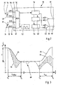
- a gate 10 is shown as a passage barrier, as used for example in security areas at airports.
- the gate 10 comprises two door leaves 12, 14 as locking elements, which are movable between an open position and a closed position and which are arranged in an unspecified, grounded passage region of the gate 10.
- the grounding is basically not required for the invention. Nevertheless, the exemplary embodiment given below builds on the functional principle (shading mode) specified at the outset in the description as the third effect, for which reason grounding is provided in the present case.
- FIG. 1 the closed position is shown.
- the door leaves 12, 14 are drivable by means of two drives in the form of electric motors 16, 18 as drive means, wherein the door leaves 12, 14 are driven from one to the other position.
- the drive 16 can move the door leaf 12, whereas the drive 18 can move the door leaf 12. Via a controller 20, the drives 16, 18 are controllable.
- the door leaves 12, 14 have two capacitive sensors 22, 24, each of the sensors 22, 24 being formed by a pair of open conductor loops 26, 28, 30, 32.
- the open conductor loops 26, 28, 30, 32 are formed integrally with the door wings 12, 14 by being applied to the surface of the door leaves 12, 14 by a suitable manufacturing method as a conductive layer.
- the door leaves 12, 14 are in the present case formed from a safety glass, on which the open conductor loops 26, 28, 30, 32 are vapor-deposited.
- the sensor 22 is formed by the open conductor loops 26, 28 and the sensor 24 by the open conductor loops 30, 32. As out Fig. 1 it can be seen that each of the two sensors 22, 24 is thus arranged in half on one of the door leaves 12, 14.
- the open conductor loops 26, 28, 30, 32 are guided for contacting purposes in the articulation region of the door wings 12, 14, where they are contacted by means of corresponding, not designated electrical lines to the open conductor loops 26, 28, 30, 32 to an evaluation circuit 36th to connect as sensor unit ( Fig. 2 ).
- Fig. 2 shows a schematic block diagram representation of the evaluation circuit 36, to which the sensors 22, 24 are connected with their open conductor loops 26, 28, 30, 32.
- the evaluation circuit 36 connection contacts 38, 40, 42, 44, to which as in Fig. 2 represented, the open conductor loops 26, 28, 30, 32 are connected.
- the connection contacts 38, 40, 42, 44 are routed internally in the evaluation circuit 36 to a multiplexer 50 which mutually connects the sensors 22, 24 alternately in time multiplex with the other required for the operation and the evaluation of the sensors 22, 24 modules.
- a generator which generates an AC signal with a predetermined edge steepness.
- This signal is also applied to the multiplexer 50, via which the alternating voltage signal is alternately switched to the terminal contact 40 and 44, respectively.
- the two connection contacts 38, 40 are switched alternately by means of the multiplexer 50 to a signal evaluation unit 54, which evaluates the signals and prepares them for further processing.
- the output signal of the signal evaluation unit 54 is switched to the positive input of two comparators 60, 62 which supply this Compare signal with reference signals of the reference signal generator I and II 56, 58.
- the outputs of the comparators 60, 62 are routed to the connection contacts 46, 48 of the evaluation circuit 36.
- the controller 20 is connected via unspecified connection lines.
- the two open conductor loops 26, 28 of the sensor 22 and the two open conductor loops 30, 32 of the sensor 24 form from the perspective of the evaluation circuit 36 variable capacitors whose capacitance is to be measured.
- an electric field therefore forms between the two door leaves 12, 14, which in the stationary case is essentially invariable and the evaluation circuit 36 simulates a predefinable rest capacity of the sensor 22, 24. If a dielectrically permeable body now moves into a spatial region 34 in the region of the door leaves 12, 14, then the stationary electric field changes, so that a capacitance change occurs which can be detected by the evaluation circuit 36.
- the signal evaluation unit 54 As soon as a sufficient change in capacitance has been detected, the signal evaluation unit 54 generates a signal which exceeds the respective reference signal of the reference signal generators I and II 56, 58, whereupon the corresponding active comparator I or II 60, 62 outputs a respective output signal to its corresponding terminal 46, 48 , This is communicated to the controller 20 connected to the ports 46, 48 for further control purposes.
- the invention thus makes it possible to detect the movement of a body, in particular the movement of a person in the space area 34 in the region of the door leaf 12, 14 and to transmit it to the controller 20.
- the evaluation circuit 34 may be integrated into the controller 20.
- the drives 16, 18 are deactivated by the controller 20. This makes it possible that the door leaves 12, 14 are freely movable, so that a person located in the pivoting range of the door leaves 12, 14 can push away the door leaves 12, 14 without injuring themselves. Alternatively, it can also be provided that the drives are abruptly braked and detected.
- the passage barrier 10 has a test unit into which a passage-desiring person enters an authorization card. If the authorization recognized as valid, the door leaves 12, 14 are moved by means of the controller 20 and the drives 16, 18 in the open position. In the open position of the door leaves 12, 14, the passage of the person wishing to pass is detected by means of the sensors 22, 24. Once the person has passed the passage barrier 10 and is outside of the space 34 in the area of the door wings 12, 14, by means of the controller 20 and the drives 16, 18 automatically closing the passage barrier 10 executed by the door leaves 12, 14 in the closed Position to be moved. Furthermore, the passage of the person is tracked and recorded. This makes it possible to create a person-related passage profile of the person. In this way, an authorization profile can be created so that a person-related authorization can be verified on the basis of the continuity profile. In the event of a deviation, a message can be sent to a control center or the like.
- the sensors 22, 24 can also be monitored at the same time the position of the door leaves 12, 14 to each other. This makes it possible to monitor opening movements or closing movements of the door leaves 12, 14 substantially continuously or even with discrete timing. In addition, this embodiment makes it possible to move the door leaves 12, 14 in predeterminable intermediate positions.
- the sensors 22, 24 of the adjacent passage barriers 10 are time-multiplexed and evaluated, so that mutual interference can be avoided.
- a higher-level control can be provided, which controls the controller 20 and the evaluation circuit 36 accordingly.
- the control changes in a 100 ms cycle.
- the evaluation circuit 36 is electrically connected directly or indirectly to ground.
- the reference values of the reference signal transmitters I and II 56, 58 can be designed to be adjustable or programmable.
- the reference signals can be adjusted accordingly.
- the reference values can be adjusted depending on the respective position of the blocking elements 12, 14.
- the evaluation circuit 36 itself may have means for tracking the reference signals, for example, to be able to compensate for boundary conditions such as humidity and the like.
- the sensors 22, 24 are automatically adjusted.
- the automatic adjustment can be carried out, for example, by additional evaluations of the detected signals, in particular the signal of the signal evaluation unit 54.
- another differentiation can be provided, with the rapid changes compared to slow changes such as changes in temperature, humidity or the like can be detected.
- Fig. 3 shows a diagram for the time course of a capacitance change, as it may occur, for example, in a normal operation of the gate 10.
- the abscissa shows the time and the ordinate the capacity.
- a solid line 64 represents the measured capacitance change during opening and subsequent closing of the doors 12, 14.
- the door leaves 12, 14 are moved to the open position in the time range between t 1 and t 2 . This leads to a decrease in capacity, which can be detected by means of the evaluation circuit 36.
- the gate 10 In the time range between t 2 and t 3 , the gate 10 is in the passage position in which the door leaves 12, 14 remain in the open position.
- a dashed curve 66 in FIG Fig. 3 represents the opening and closing of the door leaves 12, 14, as described above with reference to the solid curve, wherein additionally a person enters the space area 34. It can clearly be seen that in the period from t 1 to t 2 the capacity significantly stronger and significantly faster when opening the door leaves 12, 14 decreases, as would be the case without the action of the person. In the open position in the period t 2 to t 3 , a capacitance initially arises, as it also occurs in the solid curve 64. Only when the person passes through the door leaves 12, 14 is again a capacitance change recognizable (reference numeral 68), which pivots after passing the person in the open state of the door feet 12, 14 back to the value, as shown by the solid curve 66.
- the trace shown here shows the behavior of a measurement setup that responds to negative capacity changes. (Grounded electrically conductive body, earth-related measuring voltage).
- negative capacity changes For the time range t 3 to t 4 , the limit of recognizability is indicated on the basis of the upper dashed curve 70.
- the system responds to negative capacity changes. However, during the time range t 3 to t 4 , the capacity increases continuously.
- a stationary electric field may also be a stationary alternating electric field having a predetermined frequency and amplitude.
Landscapes
- Engineering & Computer Science (AREA)
- Civil Engineering (AREA)
- Structural Engineering (AREA)
- Mechanical Engineering (AREA)
- Power-Operated Mechanisms For Wings (AREA)
Priority Applications (7)
| Application Number | Priority Date | Filing Date | Title |
|---|---|---|---|
| HUE08019499A HUE029995T2 (en) | 2008-11-07 | 2008-11-07 | Capacitive sensing passage closing device |
| PL08019499T PL2184435T3 (pl) | 2008-11-07 | 2008-11-07 | Bramka kontroli dostępu z czujnikiem pojemnościowym |
| DK08019499.6T DK2184435T3 (en) | 2008-11-07 | 2008-11-07 | Through-lock with capacitive sensor |
| EP08019499.6A EP2184435B1 (de) | 2008-11-07 | 2008-11-07 | Durchgangssperre mit kapazitivem Sensor |
| ES08019499.6T ES2582553T3 (es) | 2008-11-07 | 2008-11-07 | Barrera de paso con sensor capacitivo |
| CA2684700A CA2684700A1 (en) | 2008-11-07 | 2009-11-06 | Entrance barrier |
| US12/613,856 US8416056B2 (en) | 2008-11-07 | 2009-11-06 | Entrance barrier |
Applications Claiming Priority (1)
| Application Number | Priority Date | Filing Date | Title |
|---|---|---|---|
| EP08019499.6A EP2184435B1 (de) | 2008-11-07 | 2008-11-07 | Durchgangssperre mit kapazitivem Sensor |
Publications (2)
| Publication Number | Publication Date |
|---|---|
| EP2184435A1 EP2184435A1 (de) | 2010-05-12 |
| EP2184435B1 true EP2184435B1 (de) | 2016-06-29 |
Family
ID=40438603
Family Applications (1)
| Application Number | Title | Priority Date | Filing Date |
|---|---|---|---|
| EP08019499.6A Not-in-force EP2184435B1 (de) | 2008-11-07 | 2008-11-07 | Durchgangssperre mit kapazitivem Sensor |
Country Status (7)
| Country | Link |
|---|---|
| US (1) | US8416056B2 (pl) |
| EP (1) | EP2184435B1 (pl) |
| CA (1) | CA2684700A1 (pl) |
| DK (1) | DK2184435T3 (pl) |
| ES (1) | ES2582553T3 (pl) |
| HU (1) | HUE029995T2 (pl) |
| PL (1) | PL2184435T3 (pl) |
Families Citing this family (14)
| Publication number | Priority date | Publication date | Assignee | Title |
|---|---|---|---|---|
| FR2976389B1 (fr) * | 2011-06-09 | 2016-07-15 | Thales Sa | Systeme de controle d'acces a une zone reservee et procede de commande d'un tel systeme. |
| CN102222380B (zh) * | 2011-06-30 | 2013-03-20 | 广州市地下铁道总公司 | 横向水平移动机构及采用该机构的自动检票机门禁装置 |
| ITMI20111605A1 (it) * | 2011-09-07 | 2013-03-08 | Taemi S R L | Sbarramento mobile per il controllo di accessi in genere. |
| CN103981822B (zh) * | 2014-06-05 | 2017-03-29 | 东莞市达维电子科技有限公司 | 一种智能无障碍通道翼闸设备 |
| CN104299297B (zh) * | 2014-08-28 | 2016-11-16 | 绵阳市绵州通有限责任公司 | 一种可重复使用的进出口限行装置的使用方法 |
| CN105488883A (zh) * | 2015-12-12 | 2016-04-13 | 张晓刚 | 紧急情况安全门打开装置 |
| EP3287585A1 (en) * | 2016-08-22 | 2018-02-28 | Captron Electronic GmbH | Capacitive jam protection |
| EP3519660B1 (en) * | 2016-09-30 | 2023-10-25 | Conduent Business Services LLC | Access barrier, related devices and related methods |
| CN106836059A (zh) * | 2017-04-06 | 2017-06-13 | 深圳市嘉昱机电有限公司 | 智能摆闸系统 |
| IT201800009238A1 (it) * | 2018-10-08 | 2020-04-08 | Gunnebo Entrance Control Ltd | Swing/wing gate turnstile |
| CN109544402A (zh) * | 2018-11-28 | 2019-03-29 | 浙江理工大学 | 一种基于电容传感器的景区防逃票方法及系统 |
| CN109706860B (zh) * | 2019-01-07 | 2021-03-23 | 浙江理工大学 | 基于电容传感器的地铁闸机防逃票系统及方法 |
| DE102020002894B4 (de) | 2020-05-14 | 2022-07-07 | Martin Eberlein | Durchgangsanlage |
| DE102022124736B3 (de) | 2022-09-27 | 2023-12-14 | Scheidt & Bachmann Gmbh | Gateanordnung, insbesondere für ein Personentransportsystem |
Family Cites Families (11)
| Publication number | Priority date | Publication date | Assignee | Title |
|---|---|---|---|---|
| US5027552A (en) * | 1990-08-16 | 1991-07-02 | Miller Edge, Inc. | Redundant sensing edge for a door for detecting an object in proximity to the door edge |
| US6337549B1 (en) * | 2000-05-12 | 2002-01-08 | Anthony Gerald Bledin | Capacitive anti finger trap proximity sensor |
| EP1235190B8 (de) * | 2001-02-21 | 2005-06-22 | Kiekert Aktiengesellschaft | Schlüssellose Betätigungs und/oder Schliesseinrichtung |
| US7162928B2 (en) * | 2004-12-06 | 2007-01-16 | Nartron Corporation | Anti-entrapment system |
| US6782759B2 (en) * | 2001-07-09 | 2004-08-31 | Nartron Corporation | Anti-entrapment system |
| US7293467B2 (en) * | 2001-07-09 | 2007-11-13 | Nartron Corporation | Anti-entrapment system |
| US7132642B2 (en) * | 2001-07-09 | 2006-11-07 | Nartron Corporation | Anti-entrapment systems for preventing objects from being entrapped by translating devices |
| DE10248761B4 (de) * | 2002-10-18 | 2013-10-02 | Wilhelm Karmann Gmbh | Kapazitiv messender Sensor und Detektionseinrichtung mit einer kapazitiven Sensorik zum Detektieren einer Einklemmsituation |
| US7312591B2 (en) * | 2005-03-11 | 2007-12-25 | Npc Corporation | Powered panel moving system |
| US7342373B2 (en) * | 2006-01-04 | 2008-03-11 | Nartron Corporation | Vehicle panel control system |
| DE202006010813U1 (de) * | 2006-07-13 | 2007-11-22 | Brose Fahrzeugteile Gmbh & Co. Kommanditgesellschaft, Coburg | Einklemmsensor sowie Auswerteschaltung |
-
2008
- 2008-11-07 PL PL08019499T patent/PL2184435T3/pl unknown
- 2008-11-07 EP EP08019499.6A patent/EP2184435B1/de not_active Not-in-force
- 2008-11-07 ES ES08019499.6T patent/ES2582553T3/es active Active
- 2008-11-07 HU HUE08019499A patent/HUE029995T2/en unknown
- 2008-11-07 DK DK08019499.6T patent/DK2184435T3/en active
-
2009
- 2009-11-06 CA CA2684700A patent/CA2684700A1/en not_active Abandoned
- 2009-11-06 US US12/613,856 patent/US8416056B2/en not_active Expired - Fee Related
Also Published As
| Publication number | Publication date |
|---|---|
| HUE029995T2 (en) | 2017-04-28 |
| CA2684700A1 (en) | 2010-05-07 |
| EP2184435A1 (de) | 2010-05-12 |
| US20100117785A1 (en) | 2010-05-13 |
| ES2582553T3 (es) | 2016-09-13 |
| DK2184435T3 (en) | 2016-10-03 |
| US8416056B2 (en) | 2013-04-09 |
| PL2184435T3 (pl) | 2017-01-31 |
Similar Documents
| Publication | Publication Date | Title |
|---|---|---|
| EP2184435A1 (de) | Durchgangssperre mit kapazitivem Sensor | |
| EP2384294B1 (de) | Einrichtung zum berührungslosen betätigen eines beweglichen teils eines fahrzeugs | |
| EP2531384B1 (de) | Virtueller schalter und verfahren zum betrieb eines solchen | |
| EP2033313B1 (de) | Einklemmsensor | |
| EP2568605B1 (de) | Kapazitive Sensoranordnung | |
| EP2880235B1 (de) | VERFAHREN ZUR STEUERUNG EINER VERSTELLBEWEGUNG EINES FAHRZEUGSCHLIEßELEMENTS MIT KOLLISIONSVERMEIDUNG FÜR EINEN SCHLOSSBEREICH UND EINKLEMMSCHUTZSYSTEM | |
| DE102010002559B4 (de) | Kapazitive Sensorvorrichtung zur Schaltung einer Türöffnung an einem Kraftfahrzeug und Stoßfänger damit | |
| EP2880763B1 (de) | Verfahren zur steuerung eines kapazitiven einklemmschutzsystems und einklemmschutzsystem | |
| EP3361032A1 (de) | Verfahren und vorrichtung zum steuern einer tür, vorzugsweise schiebetür | |
| EP2062359A2 (de) | Einklemmschutzvorrichtung | |
| EP2062360A1 (de) | Einklemmschutz | |
| DE102014117823A1 (de) | Lenkrad für ein Kraftfahrzeug mit einem Sensorsystem und Verfahren zum Erkennen einer Anwesenheit einer menschlichen Hand in einem Greifbereich eines solchen Lenkrads | |
| WO2014114669A2 (de) | Kapazitiver näherungssensor | |
| DE102013100624A1 (de) | Aufprallsensor mit triboelektrischem Effekt für ein Kraftfahrzeug | |
| EP1828524A1 (de) | Sensor mit kapazitivem messprinzip | |
| DE102012102060A1 (de) | Kapazitive Sensoranordnung an einem Kraftfahrzeug zur Erfassung von Bewegungsgesten | |
| DE102013102237A1 (de) | Kapazitiver Positionsschalter | |
| EP3309965B1 (de) | Sensorsystem | |
| EP3680692B1 (de) | Kapazitives sensorsystem | |
| DE102012021701A1 (de) | Sensorsystem zur Detektion der Annäherung von Personen oder Gegenständen, Verfahren zum Betreiben des Sensorsystems sowie dessen Verwendung | |
| DE102012022927A1 (de) | Kapazitiver Näherungssensor | |
| EP4320329B1 (de) | Detektion und vermeidung eines einklemmereignisses | |
| WO2012016953A1 (de) | Passiver magnetschalter und verfahren zur bestimmung eines magnetfeldes | |
| WO2019110696A1 (de) | Verteiltes sensorsystem zur erfassung von körperteilen und personen in den gefahrenbereichen eines cabrioverdecks | |
| EP3446297B1 (de) | Sensorvorrichtung und verfahren zum überwachen eines belegungszustands eines stellplatzes eines parkplatzes sowie parkplatz |
Legal Events
| Date | Code | Title | Description |
|---|---|---|---|
| PUAI | Public reference made under article 153(3) epc to a published international application that has entered the european phase |
Free format text: ORIGINAL CODE: 0009012 |
|
| 17P | Request for examination filed |
Effective date: 20100320 |
|
| AK | Designated contracting states |
Kind code of ref document: A1 Designated state(s): AT BE BG CH CY CZ DE DK EE ES FI FR GB GR HR HU IE IS IT LI LT LU LV MC MT NL NO PL PT RO SE SI SK TR |
|
| AX | Request for extension of the european patent |
Extension state: AL BA MK RS |
|
| AKX | Designation fees paid |
Designated state(s): AT BE BG CH CY CZ DE DK EE ES FI FR GB GR HR HU IE IS IT LI LT LU LV MC MT NL NO PL PT RO SE SI SK TR |
|
| 17Q | First examination report despatched |
Effective date: 20150205 |
|
| GRAP | Despatch of communication of intention to grant a patent |
Free format text: ORIGINAL CODE: EPIDOSNIGR1 |
|
| RIC1 | Information provided on ipc code assigned before grant |
Ipc: E05D 15/54 20060101ALI20160310BHEP Ipc: E06B 11/08 20060101AFI20160310BHEP |
|
| INTG | Intention to grant announced |
Effective date: 20160330 |
|
| GRAS | Grant fee paid |
Free format text: ORIGINAL CODE: EPIDOSNIGR3 |
|
| GRAA | (expected) grant |
Free format text: ORIGINAL CODE: 0009210 |
|
| AK | Designated contracting states |
Kind code of ref document: B1 Designated state(s): AT BE BG CH CY CZ DE DK EE ES FI FR GB GR HR HU IE IS IT LI LT LU LV MC MT NL NO PL PT RO SE SI SK TR |
|
| REG | Reference to a national code |
Ref country code: GB Ref legal event code: FG4D Free format text: NOT ENGLISH |
|
| REG | Reference to a national code |
Ref country code: CH Ref legal event code: EP |
|
| REG | Reference to a national code |
Ref country code: AT Ref legal event code: REF Ref document number: 809262 Country of ref document: AT Kind code of ref document: T Effective date: 20160715 |
|
| REG | Reference to a national code |
Ref country code: IE Ref legal event code: FG4D Free format text: LANGUAGE OF EP DOCUMENT: GERMAN |
|
| REG | Reference to a national code |
Ref country code: DE Ref legal event code: R096 Ref document number: 502008014331 Country of ref document: DE |
|
| REG | Reference to a national code |
Ref country code: ES Ref legal event code: FG2A Ref document number: 2582553 Country of ref document: ES Kind code of ref document: T3 Effective date: 20160913 |
|
| REG | Reference to a national code |
Ref country code: DK Ref legal event code: T3 Effective date: 20160927 |
|
| REG | Reference to a national code |
Ref country code: NL Ref legal event code: FP |
|
| REG | Reference to a national code |
Ref country code: SE Ref legal event code: TRGR |
|
| REG | Reference to a national code |
Ref country code: LT Ref legal event code: MG4D |
|
| PG25 | Lapsed in a contracting state [announced via postgrant information from national office to epo] |
Ref country code: LT Free format text: LAPSE BECAUSE OF FAILURE TO SUBMIT A TRANSLATION OF THE DESCRIPTION OR TO PAY THE FEE WITHIN THE PRESCRIBED TIME-LIMIT Effective date: 20160629 Ref country code: FI Free format text: LAPSE BECAUSE OF FAILURE TO SUBMIT A TRANSLATION OF THE DESCRIPTION OR TO PAY THE FEE WITHIN THE PRESCRIBED TIME-LIMIT Effective date: 20160629 |
|
| REG | Reference to a national code |
Ref country code: NO Ref legal event code: T2 Effective date: 20160629 |
|
| REG | Reference to a national code |
Ref country code: FR Ref legal event code: PLFP Year of fee payment: 9 |
|
| PG25 | Lapsed in a contracting state [announced via postgrant information from national office to epo] |
Ref country code: LV Free format text: LAPSE BECAUSE OF FAILURE TO SUBMIT A TRANSLATION OF THE DESCRIPTION OR TO PAY THE FEE WITHIN THE PRESCRIBED TIME-LIMIT Effective date: 20160629 Ref country code: GR Free format text: LAPSE BECAUSE OF FAILURE TO SUBMIT A TRANSLATION OF THE DESCRIPTION OR TO PAY THE FEE WITHIN THE PRESCRIBED TIME-LIMIT Effective date: 20160930 Ref country code: HR Free format text: LAPSE BECAUSE OF FAILURE TO SUBMIT A TRANSLATION OF THE DESCRIPTION OR TO PAY THE FEE WITHIN THE PRESCRIBED TIME-LIMIT Effective date: 20160629 |
|
| PG25 | Lapsed in a contracting state [announced via postgrant information from national office to epo] |
Ref country code: EE Free format text: LAPSE BECAUSE OF FAILURE TO SUBMIT A TRANSLATION OF THE DESCRIPTION OR TO PAY THE FEE WITHIN THE PRESCRIBED TIME-LIMIT Effective date: 20160629 Ref country code: RO Free format text: LAPSE BECAUSE OF FAILURE TO SUBMIT A TRANSLATION OF THE DESCRIPTION OR TO PAY THE FEE WITHIN THE PRESCRIBED TIME-LIMIT Effective date: 20160629 Ref country code: IS Free format text: LAPSE BECAUSE OF FAILURE TO SUBMIT A TRANSLATION OF THE DESCRIPTION OR TO PAY THE FEE WITHIN THE PRESCRIBED TIME-LIMIT Effective date: 20161029 Ref country code: SK Free format text: LAPSE BECAUSE OF FAILURE TO SUBMIT A TRANSLATION OF THE DESCRIPTION OR TO PAY THE FEE WITHIN THE PRESCRIBED TIME-LIMIT Effective date: 20160629 Ref country code: IT Free format text: LAPSE BECAUSE OF FAILURE TO SUBMIT A TRANSLATION OF THE DESCRIPTION OR TO PAY THE FEE WITHIN THE PRESCRIBED TIME-LIMIT Effective date: 20160629 |
|
| PG25 | Lapsed in a contracting state [announced via postgrant information from national office to epo] |
Ref country code: PT Free format text: LAPSE BECAUSE OF FAILURE TO SUBMIT A TRANSLATION OF THE DESCRIPTION OR TO PAY THE FEE WITHIN THE PRESCRIBED TIME-LIMIT Effective date: 20161031 |
|
| REG | Reference to a national code |
Ref country code: DE Ref legal event code: R097 Ref document number: 502008014331 Country of ref document: DE |
|
| REG | Reference to a national code |
Ref country code: HU Ref legal event code: AG4A Ref document number: E029995 Country of ref document: HU |
|
| PLBE | No opposition filed within time limit |
Free format text: ORIGINAL CODE: 0009261 |
|
| STAA | Information on the status of an ep patent application or granted ep patent |
Free format text: STATUS: NO OPPOSITION FILED WITHIN TIME LIMIT |
|
| 26N | No opposition filed |
Effective date: 20170330 |
|
| REG | Reference to a national code |
Ref country code: CH Ref legal event code: PL |
|
| PG25 | Lapsed in a contracting state [announced via postgrant information from national office to epo] |
Ref country code: LI Free format text: LAPSE BECAUSE OF NON-PAYMENT OF DUE FEES Effective date: 20161130 Ref country code: CH Free format text: LAPSE BECAUSE OF NON-PAYMENT OF DUE FEES Effective date: 20161130 |
|
| PG25 | Lapsed in a contracting state [announced via postgrant information from national office to epo] |
Ref country code: SI Free format text: LAPSE BECAUSE OF FAILURE TO SUBMIT A TRANSLATION OF THE DESCRIPTION OR TO PAY THE FEE WITHIN THE PRESCRIBED TIME-LIMIT Effective date: 20160629 Ref country code: BG Free format text: LAPSE BECAUSE OF FAILURE TO SUBMIT A TRANSLATION OF THE DESCRIPTION OR TO PAY THE FEE WITHIN THE PRESCRIBED TIME-LIMIT Effective date: 20160929 |
|
| PG25 | Lapsed in a contracting state [announced via postgrant information from national office to epo] |
Ref country code: LU Free format text: LAPSE BECAUSE OF NON-PAYMENT OF DUE FEES Effective date: 20161130 |
|
| REG | Reference to a national code |
Ref country code: FR Ref legal event code: PLFP Year of fee payment: 10 |
|
| REG | Reference to a national code |
Ref country code: AT Ref legal event code: MM01 Ref document number: 809262 Country of ref document: AT Kind code of ref document: T Effective date: 20161107 |
|
| PG25 | Lapsed in a contracting state [announced via postgrant information from national office to epo] |
Ref country code: AT Free format text: LAPSE BECAUSE OF NON-PAYMENT OF DUE FEES Effective date: 20161107 |
|
| PGFP | Annual fee paid to national office [announced via postgrant information from national office to epo] |
Ref country code: DK Payment date: 20171122 Year of fee payment: 10 Ref country code: CZ Payment date: 20171106 Year of fee payment: 10 Ref country code: NO Payment date: 20171124 Year of fee payment: 10 Ref country code: HU Payment date: 20171115 Year of fee payment: 10 |
|
| REG | Reference to a national code |
Ref country code: DE Ref legal event code: R082 Ref document number: 502008014331 Country of ref document: DE Representative=s name: BRINKMANN & PARTNER PATENTANWAELTE PARTNERSCHA, DE Ref country code: DE Ref legal event code: R082 Ref document number: 502008014331 Country of ref document: DE Representative=s name: RAUSCH WANISCHECK-BERGMANN BRINKMANN PARTNERSC, DE |
|
| PGFP | Annual fee paid to national office [announced via postgrant information from national office to epo] |
Ref country code: ES Payment date: 20171220 Year of fee payment: 10 Ref country code: PL Payment date: 20171102 Year of fee payment: 10 Ref country code: SE Payment date: 20171120 Year of fee payment: 10 |
|
| PG25 | Lapsed in a contracting state [announced via postgrant information from national office to epo] |
Ref country code: CY Free format text: LAPSE BECAUSE OF FAILURE TO SUBMIT A TRANSLATION OF THE DESCRIPTION OR TO PAY THE FEE WITHIN THE PRESCRIBED TIME-LIMIT Effective date: 20160629 |
|
| PG25 | Lapsed in a contracting state [announced via postgrant information from national office to epo] |
Ref country code: TR Free format text: LAPSE BECAUSE OF FAILURE TO SUBMIT A TRANSLATION OF THE DESCRIPTION OR TO PAY THE FEE WITHIN THE PRESCRIBED TIME-LIMIT Effective date: 20160629 Ref country code: MC Free format text: LAPSE BECAUSE OF FAILURE TO SUBMIT A TRANSLATION OF THE DESCRIPTION OR TO PAY THE FEE WITHIN THE PRESCRIBED TIME-LIMIT Effective date: 20160629 |
|
| PG25 | Lapsed in a contracting state [announced via postgrant information from national office to epo] |
Ref country code: MT Free format text: LAPSE BECAUSE OF FAILURE TO SUBMIT A TRANSLATION OF THE DESCRIPTION OR TO PAY THE FEE WITHIN THE PRESCRIBED TIME-LIMIT Effective date: 20160629 |
|
| REG | Reference to a national code |
Ref country code: DK Ref legal event code: EBP Effective date: 20181130 Ref country code: NO Ref legal event code: MMEP |
|
| REG | Reference to a national code |
Ref country code: SE Ref legal event code: EUG |
|
| PG25 | Lapsed in a contracting state [announced via postgrant information from national office to epo] |
Ref country code: SE Free format text: LAPSE BECAUSE OF NON-PAYMENT OF DUE FEES Effective date: 20181108 Ref country code: NO Free format text: LAPSE BECAUSE OF NON-PAYMENT OF DUE FEES Effective date: 20181130 Ref country code: CZ Free format text: LAPSE BECAUSE OF NON-PAYMENT OF DUE FEES Effective date: 20181107 |
|
| PG25 | Lapsed in a contracting state [announced via postgrant information from national office to epo] |
Ref country code: HU Free format text: LAPSE BECAUSE OF NON-PAYMENT OF DUE FEES Effective date: 20181108 |
|
| PG25 | Lapsed in a contracting state [announced via postgrant information from national office to epo] |
Ref country code: DK Free format text: LAPSE BECAUSE OF NON-PAYMENT OF DUE FEES Effective date: 20181130 |
|
| REG | Reference to a national code |
Ref country code: ES Ref legal event code: FD2A Effective date: 20200102 |
|
| PG25 | Lapsed in a contracting state [announced via postgrant information from national office to epo] |
Ref country code: ES Free format text: LAPSE BECAUSE OF NON-PAYMENT OF DUE FEES Effective date: 20181108 |
|
| PG25 | Lapsed in a contracting state [announced via postgrant information from national office to epo] |
Ref country code: PL Free format text: LAPSE BECAUSE OF NON-PAYMENT OF DUE FEES Effective date: 20181107 |
|
| PGFP | Annual fee paid to national office [announced via postgrant information from national office to epo] |
Ref country code: NL Payment date: 20221118 Year of fee payment: 15 Ref country code: IE Payment date: 20221121 Year of fee payment: 15 Ref country code: GB Payment date: 20221125 Year of fee payment: 15 Ref country code: FR Payment date: 20221129 Year of fee payment: 15 |
|
| PGFP | Annual fee paid to national office [announced via postgrant information from national office to epo] |
Ref country code: BE Payment date: 20221118 Year of fee payment: 15 |
|
| PGFP | Annual fee paid to national office [announced via postgrant information from national office to epo] |
Ref country code: DE Payment date: 20230123 Year of fee payment: 15 |
|
| P01 | Opt-out of the competence of the unified patent court (upc) registered |
Effective date: 20230525 |
|
| REG | Reference to a national code |
Ref country code: DE Ref legal event code: R119 Ref document number: 502008014331 Country of ref document: DE |
|
| REG | Reference to a national code |
Ref country code: NL Ref legal event code: MM Effective date: 20231201 |
|
| GBPC | Gb: european patent ceased through non-payment of renewal fee |
Effective date: 20231107 |
|
| REG | Reference to a national code |
Ref country code: BE Ref legal event code: MM Effective date: 20231130 |
|
| PG25 | Lapsed in a contracting state [announced via postgrant information from national office to epo] |
Ref country code: NL Free format text: LAPSE BECAUSE OF NON-PAYMENT OF DUE FEES Effective date: 20231201 |
|
| REG | Reference to a national code |
Ref country code: IE Ref legal event code: MM4A |
|
| PG25 | Lapsed in a contracting state [announced via postgrant information from national office to epo] |
Ref country code: NL Free format text: LAPSE BECAUSE OF NON-PAYMENT OF DUE FEES Effective date: 20231201 |
|
| PG25 | Lapsed in a contracting state [announced via postgrant information from national office to epo] |
Ref country code: DE Free format text: LAPSE BECAUSE OF NON-PAYMENT OF DUE FEES Effective date: 20240601 Ref country code: IE Free format text: LAPSE BECAUSE OF NON-PAYMENT OF DUE FEES Effective date: 20231107 |
|
| PG25 | Lapsed in a contracting state [announced via postgrant information from national office to epo] |
Ref country code: GB Free format text: LAPSE BECAUSE OF NON-PAYMENT OF DUE FEES Effective date: 20231107 |
|
| PG25 | Lapsed in a contracting state [announced via postgrant information from national office to epo] |
Ref country code: BE Free format text: LAPSE BECAUSE OF NON-PAYMENT OF DUE FEES Effective date: 20231130 |
|
| PG25 | Lapsed in a contracting state [announced via postgrant information from national office to epo] |
Ref country code: FR Free format text: LAPSE BECAUSE OF NON-PAYMENT OF DUE FEES Effective date: 20231130 |
|
| PG25 | Lapsed in a contracting state [announced via postgrant information from national office to epo] |
Ref country code: IE Free format text: LAPSE BECAUSE OF NON-PAYMENT OF DUE FEES Effective date: 20231107 Ref country code: GB Free format text: LAPSE BECAUSE OF NON-PAYMENT OF DUE FEES Effective date: 20231107 Ref country code: FR Free format text: LAPSE BECAUSE OF NON-PAYMENT OF DUE FEES Effective date: 20231130 Ref country code: DE Free format text: LAPSE BECAUSE OF NON-PAYMENT OF DUE FEES Effective date: 20240601 Ref country code: BE Free format text: LAPSE BECAUSE OF NON-PAYMENT OF DUE FEES Effective date: 20231130 |