EP2183025B1 - Firing patterns for deep brain transcranial magnetic stimulation - Google Patents
Firing patterns for deep brain transcranial magnetic stimulation Download PDFInfo
- Publication number
- EP2183025B1 EP2183025B1 EP08827575.5A EP08827575A EP2183025B1 EP 2183025 B1 EP2183025 B1 EP 2183025B1 EP 08827575 A EP08827575 A EP 08827575A EP 2183025 B1 EP2183025 B1 EP 2183025B1
- Authority
- EP
- European Patent Office
- Prior art keywords
- electromagnets
- target
- stimulation
- brain
- coils
- Prior art date
- Legal status (The legal status is an assumption and is not a legal conclusion. Google has not performed a legal analysis and makes no representation as to the accuracy of the status listed.)
- Active
Links
Images


Classifications
-
- A—HUMAN NECESSITIES
- A61—MEDICAL OR VETERINARY SCIENCE; HYGIENE
- A61N—ELECTROTHERAPY; MAGNETOTHERAPY; RADIATION THERAPY; ULTRASOUND THERAPY
- A61N2/00—Magnetotherapy
- A61N2/004—Magnetotherapy specially adapted for a specific therapy
- A61N2/006—Magnetotherapy specially adapted for a specific therapy for magnetic stimulation of nerve tissue
-
- A—HUMAN NECESSITIES
- A61—MEDICAL OR VETERINARY SCIENCE; HYGIENE
- A61N—ELECTROTHERAPY; MAGNETOTHERAPY; RADIATION THERAPY; ULTRASOUND THERAPY
- A61N2/00—Magnetotherapy
- A61N2/02—Magnetotherapy using magnetic fields produced by coils, including single turn loops or electromagnets
Definitions
- the devices and methods described herein relate generally to the triggering of electromagnets used for Transcranial Magnetic Stimulation.
- Transcranial Magnetic Stimulation (TMS) of the brain has been employed in a limited way to treat depression refractory to the administration of drugs.
- the number of treatable conditions may significantly increase as the depth of the target increases.
- Systems for targeting neural structures at depth e.g., Schneider and Mishelevich, U.S. Patent Application No. 10/821,807 , and Mishelevich and Schneider, U.S. Patent Application No. 11/429, 504
- TMS stimulation of deep targets would potentially permit treatment of a variety of conditions such as chronic pain, addiction, obesity, depression, Alzheimer's disease, and Parkinson's disease.
- rTMS repetitive transcranial magnetic stimulation
- Conventional rTMS repetitive transcranial magnetic stimulation
- rTMS repetitive transcranial magnetic stimulation
- the pulse-rate frequency from any given electromagnet location is preferably limited, typically to a rate of less than 50 pulses per second (i.e., 50 Hz). While limiting the frequency from a single stimulating location will protect structures superficial to the deeper target, it may be impossible to effectively stimulate a deep target because of the rapid fall off of the magnetic field (roughly 1 /(distance) 2 at short distances). Thus, different trajectories must be stimulated in turn. We have previously suggested accomplishing this by either moving the electromagnets, as is described in Schneider and Mishelevich, U.S. Patent Application No. 10/821,807 ("Robotic apparatus for targeting and producing deep, focused transcranial magnetic stimulation") or by sequentially firing electromagnets located at distributed locations.
- the approach of this latter case may avoid over-stimulating superficial neural structures at a single location and causing seizures or other undesired impacts, but to be successful, the pulsed magnetic fields must reach the target at a higher effective rate of stimulation than the pulsed magnetic fields hitting superficial tissue.
- the coordination of the orientation, timing, frequencies and power levels for controlling multiple magnets to stimulate one or more targets, and particularly deep tissue targets is a difficult task that has not yet been effectively accomplished. Described herein are methods, devices and systems for accomplishing this.
- tissue may have differing requirements in terms of the amount of function augmentation or suppression that they require, or that they can tolerate.
- one or more intermediate tissues may be inadvertently suppressed in the process, when, in fact, such tissue(s) require functional augmentation.
- US 2006/0149337 discloses a TMS system suitable for deep brain stimulation, wherein the system uses a multiple lead stimulator in which the base signal is separated into partial signals that are distributed across multiple contacts located either on different leads, or on a multi-contact lead, and the partial signals are temporally distributed across the contacts.
- Described herein are methods, devices and systems for controlling the firing of electromagnets located at different positions to stimulate at least one brain region, including deep brain regions.
- the firing may be performed at fixed, random, or mixed fixed and random intervals, and/or at different pulse rates.
- the methods described herein include methods of focusing stimulating from multiple magnets on one or more brain region so that energy from the magnets sums in a desired brain region to trigger firing of neurons (e.g., action potentials) in the target brain regions without triggering firing in adjacent (and particularly superficially located) brain regions.
- neurons e.g., action potentials
- the methods further include controlling the timing, rate, and power of each magnet in an array of magnets to achieve transcranial magnetic stimulation so that energy applied by the magnets to non-target regions is below a threshold for stimulation and energy applied to target regions is above the threshold.
- the rate of stimulation e.g., the rate that action potentials are evoked
- the rate of stimulation in target regions may be controlled to modulate the effects of stimulation of a target region.
- one or more pulses can be generated (e.g., 3, 2, 2, 1, 5 pulses etc.) at one location before moving on to the next.
- some or all the pulses can be concurrently fired from two or more locations.
- relatively few pulses per a given period of time may be fired from locations close to, and potentially stimulate the superficial tissues, but the magnetic pulses reaching the deep target location from a plurality of magnets may combine to form a pulse train that activates the desired volume of target tissue.
- the plurality of electromagnets referred to herein may be in fixed positions or may be mobile (as in Schneider and Mishelevich, U.S. Patent Application No. 10/821,807 ). The net effect at the target location is due to combined elements of temporal and spatial summation.
- This approach may also be used to take advantage of the individual properties of different brain regions, permitting each region to be stimulated with the pulse sequence that maximally contributes to the overall intended effect of the treatment. For example, adverse effects may result if pulse rates exceed 3 Hz when the pulse trajectory passes through the right dorsolateral prefrontal cortex on the way to a cingulate target. Consequently, it may benefit the overall treatment strategy to limit the rate of pulses passing through the right dorsolateral prefrontal cortex, even though a faster pulse rate would help the temporal summation effect.
- the devices, methods and systems described herein may control the stimulation of one or more brain regions, including regions previously thought to be too deep for controlled transcranial magnetic stimulation. This process may occur in configurations in which the charge pulses received by these electromagnets are simultaneous, and when the charge delivery among these coils is not simultaneous.
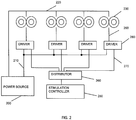
- a single power source has an output directed to multiple electromagnets by controlling which driver is gated to conduct to a given electromagnet via a distributor element controlled by a stimulation controller.
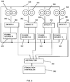
- multiple power sources (for example, one for each electromagnet) are each controlled via an associated driver. The gating of the drivers is determined by a distributor element controlled by a stimulation controller.
- Single power source and multiple power source configurations can be mixed in a single system.
- These methods, systems and devices may also allow a neuromodulation-produced energy source to simultaneously deliver different effects to different neural tissues.
- multiple stimulation trajectories or multiple stimulation sources e.g., TMS coils
- TMS coils may be controlled to achieve targeted stimulation.
- Each of these sources may be capable of independent function. The cumulative effect of the multiple sources at the intersection of their paths, as well as the independent effects of each source in proximal tissue, are calculated and controlled by the system described.
- TMS Transcranial Magnetic Stimulation
- the Transcranial Magnetic Stimulation (TMS) methods, devices and systems described herein are capable of triggering action potential (including specified patterns of action potentials) in one or more target brain regions without trigger action potential sin nearby non-target regions, including regions that are superficial (e.g., between the target region and the external magnets(s) stimulating the brain).
- These TMS systems may support a variety of action potential firing patterns by controlling the pulsing of multiple, independently triggerable, electromagnets from one or more energy sources.
- the system may also monitor or control the one or more power supplies so that there is sufficient capacity from the power supplies so when a given pulse is triggered, adequate power is available to deliver a stimulus from each electromagnet as needed to trigger the desired action potentials from the target brain region.
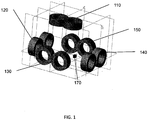
- FIG. 1 illustrates a configuration incorporating five electromagnets 110, 120, 130, 140, and 150 which may be used as part of a TMS system as described herein.
- the electromagnets need not be of equal size, and do not have to be in a uniform relationship to each other.
- the electromagnets may move as a group (say on a gantry or robotic arm) and/or in relationship to each other over time. For example, the electromagnets may be moved during stimulation (TMS) or they may be fixed during stimulation.
- TMS stimulation
- FIG. 1 a target neural (brain) tissue region 170 is illustrated. This region need not be equidistant from the electromagnets. Two or more electromagnets must be included; in the description of the embodiments illustrated in FIGS. 2 and 3 , four electromagnets are incorporated.
- the devices and systems described herein may be used to stimulate one or more regions of the brain.
- stimulation of a brain region may refer to the eliciting of one or more (or a series of) action potentials from the brain region. Deep brain regions in particular may be stimulated with these devices and methods.
- deep brain regions may refer to cortical and sub-cortical brain regions, or just sub-cortical brain regions (e.g., regions below the subject's cortex). In some variations, multiple brain regions (including a cortical and a sub-cortical brain region, two or more sub-cortical regions, etc.) may be stimulated.
- a complex pulse rhythm such as the "theta" pattern (Huang et al., 2005) on one region of the brain may facilitate TMS-induced neuromodulation effects in another part of the brain.
- the systems described herein may be used to simultaneously stimulate such a pattern in one region while simultaneously stimulating another region.
- the TMS systems described herein control the plurality of electromagnets to trigger pulses of an appropriate strength, duration and frequency (including complex patterns of stimulation), at each of the plurality of electromagnets so that only target brain region(s) are activated.
- Triggering of pulses can be done mechanically (e.g., through notches in a cam) or electronically using a built-in fixed, random, or mixed pattern or such patterns can be generated under computer control.
- the system may generate appropriate firing patterns for each of the plurality of electromagnets in the system.
- the "firing pattern" may refer to the duration of a pulse, the frequency of the pulse, and the intensity (strength) of the pulse (e.g., the current/voltage applied to generate the pulse).
- the system typically controls and coordinates the firing patterns of tall of the electromagnets.
- the electromagnets may be fired in a sequential order (e.g., first electromagnet, second electromagnet, third electromagnet, etc.) or in some other order (including random or pseudo-random).
- Table 1 An example of a sequential firing pattern is shown in Table 1 and of a random firing is shown in Table 2, below.
- electromagnets at five different locations, A through E represented in the table columns, are triggered sequentially as the process steps through times 1 through 10 represented in the table rows.
- the objective is to minimize the number of pulses received by tissues close to a given electromagnet to avoid undesirable side effects while maximizing the number of pulses stimulating the target.
- Each pulse must be of sufficient duration so that the neural membrane will not re-polarize.
- the chronaxie of a typical cortical neuron is 450 microseconds.
- the electromagnets are physically distributed such that tissues close to one electromagnet location (e.g., location "A") will be little impacted by pulses from a different location (location "B").
- pulses may be triggered at time steps 1 and 6, so at the end of time step 10, two pulses have passed through neural tissue from the electromagnet at location A.
- the same effect will be true for electromagnets at locations B through E.
- the common target will have received a pulse at each time step, albeit at a someone lower magnitude because it is further away than tissues close to the electromagnets at locations A through E.
- tissues near the individual electromagnet locations A through E will have received only two pulses where the target deep location will have received ten pulses.
- the TMS systems described herein may include control logic that coordinates the firing pattern, as well as the timing, strength and duration of the pulses applied by the electromagnets.
- This control logic (which may be part of a controller, and may be hardware, software, or both) may receive inputs regarding the subject's target anatomy (e.g., the location of one or more targets relative to the electromagnets), as well as information regarding the status of the power supply(s) indicating available power. Finally, inputs such as the desired rate of evoked action potentials for a target region may also be included. Additional inputs may be used as well. These inputs may help the control logic to determine the stimulation at each of the electromagnets, including what the firing pattern should be.
- the time interval between time steps 1 through n may be tailored to deliver the pulses at a rate that is faster than the interval at which the target neural elements (neurons of the target brain region) will re-polarize; at this faster rate, the threshold for the target neural elements will be exceeded and desired effective stimulation may occur, triggering an action potential.
- the firing rate of the individual electromagnets at locations A through n depends on the number of those individual electromagnets. For example, to achieve a pulse rate at the target to be 1000 Hz, if there are five individual electromagnets (e.g., A through E), this can be achieved by stimulating those five electromagnets at an effective rate of about 200 Hz each.
- electromagnets there are three only individual electromagnets (e.g., A through C), this can be achieved by stimulating those five electromagnets at an effective rate about 333 Hz each. All of the electromagnets need not be fired at the same frequency to achieve the effect. For example to get a pulse rate of 1000 Hz at the target, two of three electromagnets could have an effective firing rate of 400 Hz and the third could have an effective firing rate of 200 Hz. It is also not necessary that the electromagnets be of uniform type or size. In any situation involving random firing, the time interval can vary as well as the firing sequence.
- the system may also control the firing pattern in order to achieve a desired rate of stimulation of the target tissue (e.g., a rate of action potential firing).
- a desired rate of stimulation of the target tissue e.g., a rate of action potential firing
- the system may control the electromagnets so that high pulse rates (e.g., 1000 Hz) may be achieved for only a fraction of a second, for example over 5 successive pulses, closely spaced, one from each of 5 electromagnets, followed by a pause.
- the "1000 Hz" pulse burst may be experienced by neurons as a single stimulation.
- a sufficient period of wait e.g., 0.2 seconds
- the net effect experienced by a deep target tissue will of a much slower pace, for example, between 5-50 Hz.
- the same principle may be applied to the production of temporally summated multi-electromagnet bursts in the production of slow-rate or fast-rate rTMS. For example, even if 5 electromagnet are discharged once each at a 1000 Hz rate, so long as about 1 second separates the overlapping bursts (e.g., the bursts summed in the target tissue), the effective pulse rate and safety profile experienced by a given brain part will be just short of 1 Hz.
- the TMS systems described herein may therefore attend to the overall stimulation pattern while controlling each electromagnet (or groups of electromagnets) individual firing rates, durations and strengths.
- the stimulation of target tissue results from the temporal and spatial summation of the effect of the applied electromagnetic field at the target tissue.
- the system determines the appropriate firing pattern for all of the electromagnets as well as the individual firing (strength, duration and rate) for each electromagnet so that the firing of each electromagnet results in a sub-threshold energy for the non-target tissue, but the focused energy on the target tissue is above-threshold.
- controlling the power applied by the system is one part of this control.
- each electromagnet may be powered by a single power source, multiple power sources, or one power source may be used to power multiple electromagnets.
- FIG. 2 illustrates an embodiment of a TMS system in which power for the electromagnets is provided by a single energy source.
- One output of power source 200 is provided in common via connection 220 to all of the electromagnets 230. While four electromagnets 230 are shown in the figure, any number feasible in the applied geometry can be powered.
- the firing of the individual electromagnets is determined by stimulation controller 250, which activates distributor 260 to select the appropriate driver 280 which when selected at the given time delivers power via connection 210 from power source 200 to the associated electromagnet 230 via connection 290.
- FIG. 3 illustrates an embodiment in which power for the electromagnets is provided by individual power sources.
- One output of all the power sources (e.g., power sources A through D) 300, 302, 304, 306 is provided in common by connection 320 to all the electromagnets 330, 332, 334, 336.
- four electromagnets 330, 332, 334, 336 are shown in the figure, any number of electromagnets feasible to the applied geometry can be powered.
- the firing of the individual electromagnets in this example determined by stimulation controller 350, which activates distributor 360 to select the appropriate driver (e.g., drivers A through D) 380, 382, 384, or 386 which when selected at the given time delivers power via associated connection 390, 392, 394 or 396 from respective power source 300, 302, 304 or 306 to the associated electromagnet 330, 332, 334 or 336.
- the controller 350 may run the control logic coordinating the stimulation of the target while avoiding stimulation of non-target regions.
- control logic may determine the appropriate output based on the available capacity of the power source(s). This capacity may be monitored directly (e.g., by one or more inputs), based on specification, or based on calculation or estimate.
- FIG. 4 illustrates various examples of control of the firing pattern and excitation of the electromagnets (coils) that can be provided for the plurality of coils in accordance with the present invention as above described.
- Electromagnet charge storage 400 may be divided into Single Source methods 410 and Multiple Source methods 420.
- Single Source methods 410 may be subdivided into categories, as shown in FIG. 4 .
- Single Source Synchronous pulses 411 are used in order to make the single power source deliver charge to each of a plurality of coils at timings that bear a fixed relationship to one another. Examples may include simultaneous (414) pulses, and non-simultaneous (415) pulses.
- Single Source Asynchronous pulses 412 describe those in which charge from a single charge storage device is metered to a plurality of coils in a manner such that each coil fires based upon a signal other than a time scale shared by the coils.
- the initiation of asynchronous firing may in include, for example, sensing that a series of pulses delivered by one coil has finished.
- Single Source Independent pulses 413 describe those in which the activity of one coil is not synchronized with, and does not influence the activity of another coil. Very large stored charge reservoirs are required to successfully use this approach.
- Multiple Source methods may also be subdivided into categories.
- Multiple Source Synchronous pulses 421 are used in order to make the single power source deliver charge to each of a plurality of coils at timings that bear a fixed relationship to one another. Examples may include simultaneous (424) pulses, and non-simultaneous (425) pulses.
- Multiple Source Asynchronous pulses 422 describe those in which charge from a single charge storage device is metered to a plurality of coils in a manner such that each coil fires based upon a signal other than a time scale shared by the coils. The initiation of asynchronous firing may in include, for example, sensing that a series of pulses delivered by one coil has finished.
- Multiple Source Independent pulses 423 describe those in which the activity of one coil is not synchronized with, and does not influence the activity of another coil. This may be more readily accomplished than with a single source, as power may be specifically allotted to the activity of any given coil.
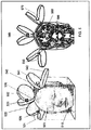
- FIG. 5 shows an array of 3 (double) stimulator coils (referred to herein as three 'electromagnets') around a patient's head, in an image based in part on image data from Voxel-Man 3D Navigator.
- the head of the subject 505 is shown transected by plane 510.
- V-shaped double coil 520 (also designated as coil A or electromagnet A) is composed of circular coils 521 and 522, and bent at the center where the return path of the current in both coils is in the same direction.
- V-shaped double coil 530 (also designated as coil B or electromagnet B) is composed of circular coils 531 and 532 joined at a bent center
- V-shaped double coil 540 (also designated as coil C or electromagnet C) is composed of circular coils 541 and 542, joined at a bent center.
- target area 580 in this example the left and right cingulum
- targeted anatomy 590 in this example, cingulate fiber bundle 580.
- the electromagnets are not V-shaped, but traditional figure-8 double coils.
- not all of the axes across the faces of the electromagnets are oriented in the same direction.
- magnetic flux reaching some locations may be augmented.
- magnetic flux reaching some locations may be neutralized.
- Coil 560 is reverse-biased with respect to coils 550 and 570, respectively, the medial aspect of the field emitted by coils 550 and 570 may be largely cancelled. This effect may be controlled by the TMS system described herein, and may be helpful in focusing the target area.
- a TMS system as described herein may be used to generate a fast rTMS pulse rate to a peripheral brain region and slow pulse rate to a deep target region.
- This pattern of stimulation (and the resulting firing pattern and set of instructions for the electromagnet) may be particularly useful for reducing dorsal anterior cingulate metabolic rate while increasing motor cortex or prefrontal metabolic rate, such as in the context of a subject being treated for pain or OCD with depression.
- the pulses are rapid but temporally staggered for a time interval that exceeds the chronaxie of the target, a rapid stimulation effect will be registered near each coil, but the target at the intersections of the energy path does not summate because of temporal staggering of the pulses from the periphery.
- a slow rate at the deep target can be achieved even as the sites at the periphery achieve a fast stimulation rate.
- the controller may receive the target information (identifying the location of the targets relative to the electromagnets), and may calculate, either before stimulation or on-the-fly, during stimulation, to achieve the desired effect.
- pulses from each of the multiple sources may be delivered in a staggered fashion so as to make pulses in the periphery slow, and pulses at the intersection of the energy fast.
- rTMS pulses are quite brief (approx 0.1 to 0.3ms in duration), there is an abundance of temporal "space" in between pulses of even a rapid train in which to deliver pulses in an asynchronous fashion, distributed between several different coils.
- FIG. 6 shows a table illustrating three example of activation of electromagnets of a TMS system similar to that shown in FIG. 5 , in order to achieve a desired effect, including three threshold-based (action-potential-elicited versus no- action-potential-elicited) calculations.
- the value of "1" means that an action potential is elicited, as the critical threshold has been exceeded.
- "0" means that no action potential has occurred, as the critical threshold value of the cumulative effect has not been exceeded.
- T1 through T10 are sample times within an interval, which in this case are defined as 0.1 ms intervals. In alternative embodiments, T1-T10 may represent different time periods. They may or may not be spaced at regular time intervals.
- Control logic e.g., part of a controller
- determine e.g., calculate
- the top table shows a scenario in which pulses are delivered from each of Coil A, Coil B, and Coil C at each of the ten time intervals. Accordingly, the summated "mutual deep target" is stimulated to action potential at each pulse, for a net deep stimulation rate of 10 Hz.
- the deep target region (at the intersection of the pulses emitted by Coils A, B, and C) is stimulated, as is the more superficial cortical regions beneath Coils A, B and C.
- Coils A and B are shown being pulsed at a fast 10Hz rate, while Coil C is pulsed a slow 1Hz rate, with a pulse only at T1. Because it is assumed that two coils at these spacing are too far from the mutual deep target to produce summation, the output at the mutual deep target is shown to be a "1", or action potential only at T1. Thus the net effect at the mutual deep target is 1 Hz stimulation, while the more superficial regions are stimulated at 10 Hz.
- Coils A and B are shown being pulsed at a fast 10Hz rate, while Coil C is pulsed a medium rate of 5 Hz, occurring at every other time interval. Because it is assumed that two coils at these spacing are too far from the mutual deep target to produce summation, the output at the mutual deep target is shown to be a "1", or action potential only at every other time interval. Thus the net effect at the mutual deep target is 5 Hz stimulation.
- the stimulation at each of the cortical regions is indicated as “100% MT” (above threshold) for stimulation at those regions.
- MT refers to motor threshold, a standard (based on stimulation of motor cortex) for evoking a response via Transcranial Magnetic Stimulation; "100% MT” or greater (e.g., "115% MT”) may result in an evoked action potential.
- the stimulation applied may be below threshold ( ⁇ 100% MT), while still summing to provide sufficient (at or above 100% MT) for the deeper brain regions.
- the cortical or regions superficial to the deep target may be un-stimulated so that they do not fire action potentials, while still stimulating the deeper region(s).
- FIGS. 7A and 7B shows two different exemplary array configurations, each consisting of four double coils around a patient's head, and centered upon the same cingulate target illustrated as the mutual deep target in FIG. 5 .
- the electromagnets may be movable during the TMS treatment, so that the position of the applied energy may be moved.
- Such a coil-moving device may be like that described in Schneider and Mishelevich, US Patent Application No. 10/821,807 .
- the TMS system may include stationary coil arrays. Stationary coils may be moved (repositioned) prior to treatment, or between treatment steps.
- coils 705, 710, 715 and 720 are in locations too distant from the dorsal anterior cingulate target 700 to effectively modulate its activity.
- FIG. 7B By moving coils into a closer pattern as shown in the lower figure, FIG. 7B , effective use of the array becomes possible.
- coils 755, 760, 770 and 780 have moved much closer together and closer to dorsal anterior cingulate target 750 in a 3D pattern overlaid upon a 2D axial slice.
- This configuration may also be achieved using three or more standard flat TMS coils, with their "flat planes" at right angles to one another, as described by the present inventors in US Patent Application 11/429,504 .
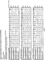
- FIG. 8 is a table that tallies (simulates) the effect of different pulse patterns of the coils shown in FIG. 7B in a manner that considers distance from each coil, and the strength of the magnetic pulses (measured continuously rather than as a binary variable), and the resultant effect upon the target structure relative to interposed superficial structures.
- the distance to the target for a given electromagnet is DTDT which is the "Distance to The Deep Target” in centimeters measured from the bottom of the cortical sulcus through which the magnetic field from that electromagnet passes.
- the falloff factor (FF) is an index that reflects what percent of an energy source is present after having traveled 1 cm from its previous position.
- the % of power at each time period (T n ) reflects the energy applied to the coil (duration and power)?
- the percent power is 115%, which is suprathreshold. In the case of 70mm double coils that may be used for TMS, this factor is approximately 0.50 (fifty percent).
- Percent power at Mutual Deep Target is the percent of target activation threshold or percent motor threshold.
- T n e.g., T1, T2... T n
- T n is an arbitrary time: these times may be equally spaced, but are not necessarily so.
- the cingulate is a bilateral structure that happens to be close to the midline, such distances may be used for both the right and left cingulate structures if target is assumed to be (for the sake of easy calculate) a point between to two cingulate bundles.
- target is assumed to be (for the sake of easy calculate) a point between to two cingulate bundles.
- the table it is illustrated that two coils in which the underlying sulci are 2.5cm from the target plus two coils in which the underlying sulci are 0.5 cm from the target, only 65% power is required from each coil to produce 115% of motor threshold at the target.
- a variant of the method illustrated by this table may be used to separately calculate the effect upon only one target at a time, based upon the distance of that target from each of the energy sources.
- any of the Transcranial Magnetic Stimulation (TMS) systems described herein are typically configured so that each electromagnet is individually controlled or instructed.
- these systems may include a controller that specifically coordinates each individual electromagnet, and the individual electromagnets are configured to be capable of acting independently of the others, so that each electromagnet may execute a separate stimulation protocol from the other electromagnets.
- the controller which may be a separate component or an integrated component in the system, and may include both hardware and software (or firmware), typically executes a stimulation strategy that includes instructions for the control of each electromagnet.
- These instructions may include controlling the position, frequency or rate of firing, strength of firing, duration of firing, shape of applied voltage/current (e.g., waveform shape), position (e.g., angle and/or distance from patient, orientation around the patient, and in some variations, movement of the electromagnet), and direction of electromagnetic field.
- the instructions for controlling stimulation executed by the controller may also be referred to as a treatment plan or treatment strategy.
- the treatment strategy may also include a stimulation pattern, indicating the pattern of firing of individual electromagnets.
- individual electromagnets may include sets (e.g. pairs, etc.) of electromagnets.
- the controller also includes logic (hardware and/or software) for generating the treatment strategy.
- logic hardware and/or software
- a separate module or component for calculating the treatment strategy may be used.
- scheduling logic may be used to generate one or more treatment strategies.
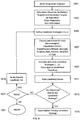
- FIG. 9 is a flowchart illustrating one method of generating a treatment strategy. In general, this treatment strategy is formulated by first determining (or inputting, e.g., by user input) the treatment objectives for each target region, as well as any other regions that may be affected by activation of the electromagnets, such as the brain regions between the electromagnet and the target.
- the first step in controlling a TMS system includes determining the deep brain tissue target(s) to be stimulated 1001. Any appropriate target may be chosen.
- the deep brain region target e.g. sub-cortical target
- the target deep region of the subject's brain chosen may be provided to the controller (or other module) of the system by numeric (e.g., providing coordinates), by graphical (e.g., indicating on a subject's brain scan), or any other appropriate means.
- the system may include brain scanning or mapping, or may receive input from brain scanning or mapping.
- the system may receive the position or coordinates of the target(s) relative to the positions of the electromagnets.
- the primary target(s) e.g., deep brain targets
- the system may determine what secondary targets may be affected by the stimulation of the target regions.
- a secondary target may also be called an incidental target or a collateral target, because, although it is not an intended target, it may be stimulated during the attempt to stimulate the intended target.
- the cortical region between the deep brain region and the electromagnet, along the pathway of the pulse emitted by the electromagnet may be considered a secondary or collateral target.
- a collateral target may also be a primary target.
- the position of the electromagnets (coils) around the subject may also be adjusted. For example, once the target deep brain region(s) have been selected, the coils around the subject heads may be moved to better reach them. In some variations, the magnets may be continuously moved (e.g., rotated, tilted, or otherwise repositioned) to reach the target region(s). The movement may be coordinated or controlled by the controller, and may be made either at the start of a treatment, or it may occur continuously or periodically during the treatment. Thus the treatment strategy may include control of magnet position and/or movement.
- the system may then determine objectives for the primary and secondary targets 1003.
- the objective may be input from the user (e.g., doctor, technician, etc.) and/or may be selected form a database of objectives.
- the objective for a particular region e.g., target region
- the objectives may be broadly characterized as "up regulation”, “down regulation” or “non-stimulation.”
- an objective of non-stimulation may be interpreted as limiting the target region (e.g., a collateral target region) so that threshold stimulation from the electromagnet (e.g., stimulation less than 100% MT for that region) is not achieved.
- threshold stimulation from the electromagnet e.g., stimulation less than 100% MT for that region
- an objective of "up-regulation” in a particular region may mean stimulation at a frequency of about 5 Hz or greater within the target region.
- an objective of "down-regulation" of a target region may refer to stimulation at a rate of 1 Hz or less.
- An inventory or database of stimulation objectives for multiple different brain regions may be used (and may be included as part of the system) to provide an adjustable default or pre-set to the system.
- the adjustable default for collateral targets may be non-stimulation.
- the system may then apply a method to determine a stimulation strategy.
- a method to determine a stimulation strategy is shown in FIG. 9 , steps 1005-1019.
- the system may generate a plurality of candidate strategies 1005 (e.g., m candidate strategies) by applying the target strategies, then score these strategies after simulating their application, and apply the highest-scoring treatment strategy.
- FIG. 11 provides one illustration of a method for choosing parameters for candidate strategies, as indicated in steps 1005 and 1007.
- the step of choosing parameters for each magnet during a treatment strategy may include generating a stimulation pattern wherein the timing of firing of each magnet in the system is coordinated.
- This stimulation pattern may be fixed, random or mixed, as described above.
- the firing characteristics of each electromagnet during the stimulation pattern may be selected, including strength, duration, shape of the applied waveform, position of the electromagnet, direction of the field, etc.
- These parameters may be constrained by the target and target objectives.
- FIG. 11 steps 2001-2027, describes on variation of a method of determining generating a target number of candidate stimulation strategies.
- permutations of strength, duration, rate, field orientation, etc. may be determined 2005 for different permutations of stimulation patterns 2003, and simulated 2015 to determine if they achieve the target objectives 2017 for both primary and collateral targets. This process can be iteratively repeated until an array of candidate strategies (or a best candidate strategy, if they are being scored and compared during this process) is identified.
- pre-set or historical treatment strategies may be applied or used as a starting point for determining a candidate treatment strategy.
- a database of treatment strategies for particular targets may be used.
- the system may include such a database, and may add to or modify this database.
- Simulation of a candidate treatment plan may be based on the application of the summation (both temporal and spatial) of the applied pulse(s) within each target region. For example, as indicated by FIG. 8 , described above, a matrix of simulated stimulation values may be generated to determine what the rate and level of stimulation is for each target region, which can then be compared against the objectives for that target region. Thus, the simulation may apply the attenuation factor, based on the location of the target region relative to the electromagnets. In some variations, particular characteristics of the tissue may also be applied (e.g., region attenuation factors, regional thresholds for stimulation, the effect of field orientations in certain regions, etc.).
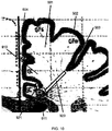
- FIG. 10 is an adaptation of a figure from the Talairach Atlas in which distances are measured from the bottom of a cortical sulci to a deep target, in this case the cingulate bundle.
- Brain 901 includes gyrus 902 (a representative example), sulci 903 (a representative example), and longitudinal fissure 904. Sulci 903 and longitudinal fissure 904 are typically filled with clear cerebrospinal fluid (not illustrated). Cerebrospinal fluid is composed principally of water with sodium chloride salt, which makes these spaces highly electrically conductive.
- Cerebrospinal fluid is composed principally of water with sodium chloride salt, which makes these spaces highly electrically conductive.
- cingulum principally gray matter but also containing cingulate bundle 910, which is composed of axons, or white matter.
- the distances between the deep target (e.g., cingulate bundle 911) and the bottom of two nearby highly conductive sulci are relatively short: distance 911 and distance 920.
- Distance 911 and distance 920 when represented in centimeters, may be used within the context of the table in FIG. 8 as DTDT (distance to deep target) numbers. Because the cingulate is a bilateral structure that happens to be close to the midline, such distances may be used for both the right and left cingulate structures if target is assumed to be a point between to two cingulate bundles.
- the net results at various locations may still be predicted and controlled.
- Fast and slow stimulation rates may be simultaneously applied to neural tissue on the periphery, while either fast or slow stimulation is being applied to the shared deep target.
- electromagnets shown in the figures are V-shaped double TMS coils, the present method is intended to be generic to any neurostimulation energy source, including, but not limited to standard (flat) double TMS coils or circular TMS coils.
- the method is also intended to generically apply to neurostimulation energy sources including but not limited to direct or alternating current electrodes, optical neurostimulation light sources, and ultrasound emitters, any of which may be either implanted, externally placed, or within natural orifices.
Landscapes
- Health & Medical Sciences (AREA)
- Engineering & Computer Science (AREA)
- Biomedical Technology (AREA)
- Nuclear Medicine, Radiotherapy & Molecular Imaging (AREA)
- Radiology & Medical Imaging (AREA)
- Life Sciences & Earth Sciences (AREA)
- Animal Behavior & Ethology (AREA)
- General Health & Medical Sciences (AREA)
- Public Health (AREA)
- Veterinary Medicine (AREA)
- Neurology (AREA)
- Magnetic Treatment Devices (AREA)
Applications Claiming Priority (4)
| Application Number | Priority Date | Filing Date | Title |
|---|---|---|---|
| US95692007P | 2007-08-20 | 2007-08-20 | |
| US97095807P | 2007-09-09 | 2007-09-09 | |
| US7748808P | 2008-07-02 | 2008-07-02 | |
| PCT/US2008/073751 WO2009026386A1 (en) | 2007-08-20 | 2008-08-20 | Firing patterns for deep brain transcranial magnetic stimulation |
Publications (2)
| Publication Number | Publication Date |
|---|---|
| EP2183025A1 EP2183025A1 (en) | 2010-05-12 |
| EP2183025B1 true EP2183025B1 (en) | 2017-07-05 |
Family
ID=39832197
Family Applications (1)
| Application Number | Title | Priority Date | Filing Date |
|---|---|---|---|
| EP08827575.5A Active EP2183025B1 (en) | 2007-08-20 | 2008-08-20 | Firing patterns for deep brain transcranial magnetic stimulation |
Country Status (6)
| Country | Link |
|---|---|
| US (2) | US8956273B2 (cg-RX-API-DMAC7.html) |
| EP (1) | EP2183025B1 (cg-RX-API-DMAC7.html) |
| JP (1) | JP2010536496A (cg-RX-API-DMAC7.html) |
| AU (1) | AU2008288967A1 (cg-RX-API-DMAC7.html) |
| CA (1) | CA2694037A1 (cg-RX-API-DMAC7.html) |
| WO (1) | WO2009026386A1 (cg-RX-API-DMAC7.html) |
Families Citing this family (55)
| Publication number | Priority date | Publication date | Assignee | Title |
|---|---|---|---|---|
| US8052591B2 (en) | 2006-05-05 | 2011-11-08 | The Board Of Trustees Of The Leland Stanford Junior University | Trajectory-based deep-brain stereotactic transcranial magnetic stimulation |
| US8267850B2 (en) | 2007-11-27 | 2012-09-18 | Cervel Neurotech, Inc. | Transcranial magnet stimulation of deep brain targets |
| US9352167B2 (en) | 2006-05-05 | 2016-05-31 | Rio Grande Neurosciences, Inc. | Enhanced spatial summation for deep-brain transcranial magnetic stimulation |
| US8795148B2 (en) | 2009-10-26 | 2014-08-05 | Cervel Neurotech, Inc. | Sub-motor-threshold stimulation of deep brain targets using transcranial magnetic stimulation |
| US20150099921A1 (en) * | 2008-11-26 | 2015-04-09 | M. Bret Schneider | Treatment of degenerative brain disorders using transcranial magnetic stimulation |
| US9180305B2 (en) * | 2008-12-11 | 2015-11-10 | Yeda Research & Development Co. Ltd. At The Weizmann Institute Of Science | Systems and methods for controlling electric field pulse parameters using transcranial magnetic stimulation |
| US8723628B2 (en) * | 2009-01-07 | 2014-05-13 | Cervel Neurotech, Inc. | Shaped coils for transcranial magnetic stimulation |
| US9492679B2 (en) | 2010-07-16 | 2016-11-15 | Rio Grande Neurosciences, Inc. | Transcranial magnetic stimulation for altering susceptibility of tissue to pharmaceuticals and radiation |
| WO2013054003A1 (en) * | 2011-10-14 | 2013-04-18 | Nexstim Oy | Method and apparatus for approximating effects of transcranial magnetic stimulation to a brain |
| FI20116085A7 (fi) | 2011-11-03 | 2013-05-04 | Nexstim Oy | Menetelmä ja laite aivojen transkraniaalisen stimulaation vaikutusten määrittämiseksi |
| MX344672B (es) | 2012-04-06 | 2017-01-04 | Kosivana Holdings Ltd | Dispositivo de estimulacion magnetica transcraneal repetitiva. |
| DE102012013534B3 (de) | 2012-07-05 | 2013-09-19 | Tobias Sokolowski | Vorrichtung für repetitive Nervenstimulation zum Abbau von Fettgewebe mittels induktiver Magnetfelder |
| US9849301B2 (en) * | 2014-01-15 | 2017-12-26 | Neuronetics, Inc. | Magnetic stimulation coils and ferromagnetic components for reduced surface stimulation and improved treatment depth |
| US9457188B2 (en) | 2014-03-03 | 2016-10-04 | Medtronic, Inc. | Therapeutic window determination |
| CA2857555A1 (en) | 2014-04-01 | 2015-10-01 | William F. Stubbeman | Method and system for therapeutic brain stimulation using electromagnetic pulses |
| EP3125986B1 (en) | 2014-04-02 | 2019-03-06 | University of Maryland, Baltimore | Systems for controlling magnetic fields and magnetic field induced current |
| US20170106203A1 (en) * | 2014-05-30 | 2017-04-20 | Rio Grande Neuroscences, Inc. | Control of spike-timing dependent brain network plasticity via multi-coil transcranial magnetic stimulation |
| US10583293B2 (en) | 2014-09-09 | 2020-03-10 | Medtronic, Inc. | Therapy program selection for electrical stimulation therapy based on a volume of tissue activation |
| WO2017004156A1 (en) * | 2015-06-30 | 2017-01-05 | University Of Maryland, Baltimore | Methods and systems for controlling magnetic fields and magnetic field induced current |
| US11491342B2 (en) | 2015-07-01 | 2022-11-08 | Btl Medical Solutions A.S. | Magnetic stimulation methods and devices for therapeutic treatments |
| US10695575B1 (en) | 2016-05-10 | 2020-06-30 | Btl Medical Technologies S.R.O. | Aesthetic method of biological structure treatment by magnetic field |
| US20180001107A1 (en) | 2016-07-01 | 2018-01-04 | Btl Holdings Limited | Aesthetic method of biological structure treatment by magnetic field |
| US10307607B2 (en) * | 2016-02-09 | 2019-06-04 | Palo Alto Research Center Incorporated | Focused magnetic stimulation for modulation of nerve circuits |
| US11464993B2 (en) | 2016-05-03 | 2022-10-11 | Btl Healthcare Technologies A.S. | Device including RF source of energy and vacuum system |
| US11247039B2 (en) | 2016-05-03 | 2022-02-15 | Btl Healthcare Technologies A.S. | Device including RF source of energy and vacuum system |
| US11534619B2 (en) | 2016-05-10 | 2022-12-27 | Btl Medical Solutions A.S. | Aesthetic method of biological structure treatment by magnetic field |
| WO2017195309A1 (ja) * | 2016-05-12 | 2017-11-16 | 株式会社日立製作所 | エネルギー照射装置 |
| US10583287B2 (en) | 2016-05-23 | 2020-03-10 | Btl Medical Technologies S.R.O. | Systems and methods for tissue treatment |
| US10556122B1 (en) | 2016-07-01 | 2020-02-11 | Btl Medical Technologies S.R.O. | Aesthetic method of biological structure treatment by magnetic field |
| US11141219B1 (en) | 2016-08-16 | 2021-10-12 | BTL Healthcare Technologies, a.s. | Self-operating belt |
| CA3046392A1 (en) * | 2016-12-22 | 2018-06-28 | Sunnybrook Research Institute | Systems and methods for performing transcranial ultrasound therapeutic and imaging procedures |
| US10912941B2 (en) | 2017-01-05 | 2021-02-09 | Regents Of The University Of Minnesota | System and method for feedback-driven neuromodulation |
| FI129532B (en) | 2017-04-03 | 2022-04-14 | Aalto Korkeakoulusaeaetioe | Control of transcranial magnetic stimulation |
| US20190167982A1 (en) * | 2017-12-06 | 2019-06-06 | Y-Brain Inc. | Stimulation health care module |
| US11266849B2 (en) * | 2017-12-12 | 2022-03-08 | Eb Neuro S.P.A. | Control device and a machine for interactive cerebral and bodily navigation with real-time anatomical display and control functions |
| WO2019150378A1 (en) * | 2018-02-05 | 2019-08-08 | Brainsway Ltd. | Electromagnetic coil assembly |
| US12186555B2 (en) * | 2018-02-06 | 2025-01-07 | Stimit Ag | Ventilation machine and method of ventilating a patient |
| RU2725067C2 (ru) * | 2018-04-24 | 2020-06-29 | Общество С Ограниченной Ответственностью "Центр Нейротехнологий Сна И Бодрствования" (Ооо "Цнсиб") | Способ и система физиотерапевтической коррекции и терапии сна человека |
| JP7201986B2 (ja) * | 2018-09-03 | 2023-01-11 | 国立大学法人 大分大学 | 神経系細胞の増殖を活性化させるための磁気の制御方法、及び経頭蓋磁気刺激システム |
| EP3627644A3 (en) * | 2018-09-24 | 2020-04-22 | Phasor Ltd | Detection and protection of power phase loss and neutral failure |
| US11890487B2 (en) | 2018-09-27 | 2024-02-06 | Yona Peled | Method and apparatus for multi-channel simultaneously high power magnetic coil driver |
| CN109481845B (zh) * | 2018-12-28 | 2022-04-01 | 深圳先进技术研究院 | 一种作用于不同脑区的经颅磁刺激的方法和相关装置 |
| US11141585B2 (en) * | 2018-12-28 | 2021-10-12 | Palo Alto Research Center Incorporated | Non-invasive neural interface |
| CN109745621A (zh) * | 2019-02-18 | 2019-05-14 | 天津大学 | 一种用于深部经颅磁刺激的多圆相切的立体线圈 |
| US10981016B2 (en) * | 2019-03-13 | 2021-04-20 | Seraya Medical Systems LLC | Identifiable magnetic assemblies and communications |
| US12156689B2 (en) | 2019-04-11 | 2024-12-03 | Btl Medical Solutions A.S. | Methods and devices for aesthetic treatment of biological structures by radiofrequency and magnetic energy |
| KR102609208B1 (ko) | 2019-04-11 | 2023-12-05 | 비티엘 메디컬 솔루션스 에이.에스. | 고주파 및 자기 에너지에 의한 생물학적 구조들의 심미적 치료를 위한 방법들 및 디바이스들 |
| US11426599B2 (en) * | 2019-11-22 | 2022-08-30 | Palo Alto Research Center Incorporated | Three-dimensional coil set used for neuromodulation |
| US11052262B1 (en) * | 2019-12-30 | 2021-07-06 | Seraya Medical Systems LLC | Stimulation of subcortical brain regions using transcranial rotating permanent magnetic stimulation (TRPMS) |
| ES2993637T3 (en) | 2020-05-04 | 2025-01-03 | Btl Healthcare Technologies As | Device for unattended treatment of a patient |
| US11878167B2 (en) | 2020-05-04 | 2024-01-23 | Btl Healthcare Technologies A.S. | Device and method for unattended treatment of a patient |
| KR20230084286A (ko) | 2020-12-16 | 2023-06-12 | 데이진 화-마 가부시키가이샤 | 경두개 자기 자극 장치 |
| EP4415812A1 (en) | 2021-10-13 | 2024-08-21 | BTL Medical Solutions a.s. | Devices for aesthetic treatment of biological structures by radiofrequency and magnetic energy |
| US11896816B2 (en) | 2021-11-03 | 2024-02-13 | Btl Healthcare Technologies A.S. | Device and method for unattended treatment of a patient |
| CN118533970B (zh) * | 2024-07-25 | 2024-09-27 | 国网山西省电力公司电力科学研究院 | 一种基于激光超声的gis组件检测系统及方法 |
Family Cites Families (134)
| Publication number | Priority date | Publication date | Assignee | Title |
|---|---|---|---|---|
| US3799164A (en) | 1971-08-12 | 1974-03-26 | Du Pont | Analgesic apparatus |
| US4134395A (en) | 1976-12-29 | 1979-01-16 | Biomagnetics International, Inc. | Method of using magnetic fields to conduct a screening diagnostic examination |
| US4889526A (en) | 1984-08-27 | 1989-12-26 | Magtech Laboratories, Inc. | Non-invasive method and apparatus for modulating brain signals through an external magnetic or electric field to reduce pain |
| JPS6446479U (cg-RX-API-DMAC7.html) | 1987-09-16 | 1989-03-22 | ||
| CA2021506A1 (en) | 1989-08-17 | 1991-02-18 | Abraham R. Liboff | Electromagnetic treatment therapy for stroke victims |
| US5207223A (en) | 1990-10-19 | 1993-05-04 | Accuray, Inc. | Apparatus for and method of performing stereotaxic surgery |
| EP0501048A1 (en) | 1991-02-25 | 1992-09-02 | Lti-Imd Usa, Inc. | Shielded electromagnetic transducer |
| JP2892181B2 (ja) | 1991-05-31 | 1999-05-17 | 照剛 上野 | 磁気刺激コイル |
| US5267938A (en) | 1991-06-24 | 1993-12-07 | Konotchick John A | Magnetic stimulation device |
| GB2271931A (en) | 1992-10-29 | 1994-05-04 | Benjamin Israel Sacks | Magnetic stimulator for medical use |
| US5427097A (en) | 1992-12-10 | 1995-06-27 | Accuray, Inc. | Apparatus for and method of carrying out stereotaxic radiosurgery and radiotherapy |
| DE9422172U1 (de) | 1993-04-26 | 1998-08-06 | St. Louis University, St. Louis, Mo. | Angabe der Position einer chirurgischen Sonde |
| GB2278783A (en) | 1993-06-11 | 1994-12-14 | Daniel Shellon Gluck | Method of magnetically stimulating neural cells |
| DE69532916D1 (de) | 1994-01-28 | 2004-05-27 | Schneider Medical Technologies | Verfahren und vorrichtung zur bilddarstellung |
| US5531227A (en) | 1994-01-28 | 1996-07-02 | Schneider Medical Technologies, Inc. | Imaging device and method |
| DE69532829T2 (de) | 1994-10-07 | 2005-01-27 | St. Louis University | Vorrichtung zur benutzung mit einem chirurgischen navigationssystem |
| EP0709115A1 (en) | 1994-10-27 | 1996-05-01 | Consiglio Nazionale Delle Ricerche | Device for applying a programmable excitation electric field to a target |
| US6132361A (en) | 1994-11-28 | 2000-10-17 | Neotonus, Inc. | Transcranial brain stimulation |
| US6425852B1 (en) | 1994-11-28 | 2002-07-30 | Emory University | Apparatus and method for transcranial magnetic brain stimulation, including the treatment of depression and the localization and characterization of speech arrest |
| GB9504216D0 (en) | 1995-03-02 | 1995-04-19 | Magstim Co Ltd | Magnetic stimulator for neuro-muscular tissue |
| WO1997000639A2 (en) | 1995-06-19 | 1997-01-09 | Holcomb Robert R | Electromagnetic treatment device and methods of using |
| US6972097B2 (en) | 1995-07-20 | 2005-12-06 | Nec Tokin Corporation | Composite magnetic material and electromagnetic interference suppressor member using the same |
| US5707334A (en) | 1995-08-21 | 1998-01-13 | Young; Robert B. | Method of treating amygdala related transitory disorders |
| EP1319422A3 (en) | 1996-02-15 | 2004-01-28 | Nihon Kohden Corporation | An apparatus for treating urinary incontinence |
| US5921244A (en) | 1997-06-11 | 1999-07-13 | Light Sciences Limited Partnership | Internal magnetic device to enhance drug therapy |
| US6132631A (en) | 1997-08-08 | 2000-10-17 | Applied Materials, Inc. | Anisotropic silicon nitride etching for shallow trench isolation in an high density plasma system |
| DE29718337U1 (de) | 1997-10-17 | 1999-02-18 | Muntermann, Axel, 35583 Wetzlar | Vorrichtung zur Magnetfeldtherapie |
| CA2306918C (en) | 1997-10-17 | 2008-04-15 | Respironics, Inc. | Muscle stimulating device and method for diagnosing and treating a breathing disorder |
| US6311082B1 (en) | 1997-11-12 | 2001-10-30 | Stereotaxis, Inc. | Digital magnetic system for magnetic surgery |
| US6212419B1 (en) | 1997-11-12 | 2001-04-03 | Walter M. Blume | Method and apparatus using shaped field of repositionable magnet to guide implant |
| US5945762A (en) | 1998-02-10 | 1999-08-31 | Light Sciences Limited Partnership | Movable magnet transmitter for inducing electrical current in an implanted coil |
| US6179771B1 (en) | 1998-04-21 | 2001-01-30 | Siemens Aktiengesellschaft | Coil arrangement for transcranial magnetic stimulation |
| GB9808764D0 (en) | 1998-04-25 | 1998-06-24 | Magstim Co Ltd | Magnetic stimulators for neuro-muscular tissue |
| US6266556B1 (en) | 1998-04-27 | 2001-07-24 | Beth Israel Deaconess Medical Center, Inc. | Method and apparatus for recording an electroencephalogram during transcranial magnetic stimulation |
| DE19819214B4 (de) | 1998-04-29 | 2004-07-01 | Markoll, Richard, Dr., Boca Raton | Vorrichtung zur Behandlung von Gewebe- und/oder Gelenkserkrankungen |
| US6198958B1 (en) | 1998-06-11 | 2001-03-06 | Beth Israel Deaconess Medical Center, Inc. | Method and apparatus for monitoring a magnetic resonance image during transcranial magnetic stimulation |
| FI105163B (fi) | 1998-07-10 | 2000-06-30 | Juha Virtanen | Menetelmä ja laite lumemagneettistimulaation tuottamiseksi |
| US6149577A (en) | 1999-03-18 | 2000-11-21 | Emf Therapeutics, Inc. | Apparatus and method for creating a substantially contained, finite magnetic field useful for relieving the symptoms pain and discomfort associated with degenerative diseases and disorders in mammals |
| JP2002539257A (ja) | 1999-03-19 | 2002-11-19 | イーノス・ファーマシューティカルス・インコーポレーテッド | 薬剤の脳内生物学的利用率の増加 |
| WO2000074777A1 (en) | 1999-06-02 | 2000-12-14 | Medinova Medical Consulting Gmbh | Transcranial magnetic stimulation (tms) for improving vision in humans |
| US6443883B1 (en) | 1999-06-08 | 2002-09-03 | Medical Bracing Systems, Ltd. | PEMF biophysical stimulation field generator device and method |
| GB9926621D0 (en) | 1999-11-11 | 2000-01-12 | Magstim Co Ltd | Stimulating coil |
| US6907280B2 (en) | 1999-12-02 | 2005-06-14 | The General Hospital Corporation | Method and apparatus for objectively measuring pain, pain treatment and other related techniques |
| US6356781B1 (en) | 2000-03-31 | 2002-03-12 | Lucent Technologies, Inc. | Functional magnetic resonance imaging capable of detecting the occurrence of neuronal events with high temporal accuracy |
| US20020097125A1 (en) | 2000-06-05 | 2002-07-25 | Kent Davey | Method for optimizing transcranial magnetic stimulation cores and magnetic cores produced thereby |
| RU2160130C1 (ru) | 2000-07-10 | 2000-12-10 | Закрытое акционерное общество "ЭКОИНВЕНТ" | Способ нормализации биологических функций живых тканей и устройство для электромагнитного воздействия на живые ткани |
| US6402678B1 (en) | 2000-07-31 | 2002-06-11 | Neuralieve, Inc. | Means and method for the treatment of migraine headaches |
| US6591138B1 (en) * | 2000-08-31 | 2003-07-08 | Neuropace, Inc. | Low frequency neurostimulator for the treatment of neurological disorders |
| US6488617B1 (en) * | 2000-10-13 | 2002-12-03 | Universal Hedonics | Method and device for producing a desired brain state |
| AU2912902A (en) | 2000-10-20 | 2002-04-29 | Us Gov Health & Human Serv | Coil for magnetic stimulation and methods for using the same |
| US6572528B2 (en) | 2001-04-20 | 2003-06-03 | Mclean Hospital Corporation | Magnetic field stimulation techniques |
| CA2443819C (en) | 2001-05-04 | 2011-07-19 | Board Of Regents, The University Of Texas System | Apparatus and methods for delivery of transcranial magnetic stimulation |
| EP1269913B1 (de) | 2001-06-28 | 2004-08-04 | BrainLAB AG | Vorrichtung für transcraniale magnetische Stimulation und kortikale Kartographie |
| ES2238365T3 (es) | 2001-06-28 | 2005-09-01 | Brainlab Ag | Aparato de estimulacion magnetica transcraneal. |
| FI114613B (fi) * | 2001-10-17 | 2004-11-30 | Nexstim Oy | Menetelmä ja laite magneettistimulaation annoslaskentaa varten |
| JP3737054B2 (ja) | 2002-01-15 | 2006-01-18 | 第一高周波工業株式会社 | 磁束照射装置 |
| US7155284B1 (en) | 2002-01-24 | 2006-12-26 | Advanced Bionics Corporation | Treatment of hypertension |
| US20050256539A1 (en) | 2002-03-25 | 2005-11-17 | George Mark S | Methods and systems for using transcranial magnetic stimulation to enhance cognitive performance |
| US20050124848A1 (en) | 2002-04-05 | 2005-06-09 | Oliver Holzner | Method and apparatus for electromagnetic modification of brain activity |
| US20050107655A1 (en) | 2002-04-05 | 2005-05-19 | Oliver Holzner | Method and apparatus for the prevention of epileptic seizures |
| US7283861B2 (en) | 2002-04-30 | 2007-10-16 | Alexander Bystritsky | Methods for modifying electrical currents in neuronal circuits |
| US20050154426A1 (en) | 2002-05-09 | 2005-07-14 | Boveja Birinder R. | Method and system for providing therapy for neuropsychiatric and neurological disorders utilizing transcranical magnetic stimulation and pulsed electrical vagus nerve(s) stimulation |
| WO2003098268A1 (en) | 2002-05-17 | 2003-11-27 | Musc Foundation For Research Development | Method, apparatus, and system for automatically positioning a probe or sensor |
| WO2004006750A2 (en) | 2002-07-15 | 2004-01-22 | Musc Foundation For Research Development | Functional magnetic resonance imaging guided transcranial magnetic stimulation deception inhibitor |
| DE10242542A1 (de) | 2002-09-13 | 2004-04-01 | Forschungszentrum Karlsruhe Gmbh | Positioniersystem für die navigierte transkranielle Magnetstimulation |
| US6899667B2 (en) | 2002-10-21 | 2005-05-31 | Paul F. Becker | Method and apparatus for the treatment of physical and mental disorders with low frequency, low flux density magnetic fields |
| US7236830B2 (en) | 2002-12-10 | 2007-06-26 | Northstar Neuroscience, Inc. | Systems and methods for enhancing or optimizing neural stimulation therapy for treating symptoms of Parkinson's disease and/or other movement disorders |
| US20060241374A1 (en) | 2002-11-20 | 2006-10-26 | George Mark S | Methods and systems for using transcranial magnetic stimulation and functional brain mapping for examining cortical sensitivity, brain communication, and effects of medication |
| US7367936B2 (en) | 2002-11-21 | 2008-05-06 | The Magstim Company Ltd. | Magnetic stimulators and coils therefor |
| US7771341B2 (en) | 2003-01-22 | 2010-08-10 | William Thomas Rogers | Electromagnetic brain animation |
| US6971984B2 (en) | 2003-02-12 | 2005-12-06 | Vincent Ardizzone | Magneto-cymatic therapeutic face mask |
| US7153256B2 (en) | 2003-03-07 | 2006-12-26 | Neuronetics, Inc. | Reducing discomfort caused by electrical stimulation |
| US8118722B2 (en) | 2003-03-07 | 2012-02-21 | Neuronetics, Inc. | Reducing discomfort caused by electrical stimulation |
| US20060199992A1 (en) | 2003-03-17 | 2006-09-07 | Eisenberg Solomon R | Magnetic stimulator |
| KR100547265B1 (ko) | 2003-03-31 | 2006-01-26 | 모승기 | 변조 기능을 갖는 펄스 자기 자극 생성 장치 및 방법 |
| US7196603B2 (en) | 2003-04-18 | 2007-03-27 | Board Of Regents, The University Of Texas System | Magnetic coil design using optimization of sinusoidal coefficients |
| CA2523540A1 (en) | 2003-04-24 | 2005-01-06 | Northstar Neuroscience, Inc. | Systems and methods for facilitating and/or effectuating development, rehabilitation, restoration, and/or recovery of visual function through neural stimulation |
| US20050033154A1 (en) | 2003-06-03 | 2005-02-10 | Decharms Richard Christopher | Methods for measurement of magnetic resonance signal perturbations |
| EP1638647A1 (en) | 2003-06-27 | 2006-03-29 | Fralex Therapeutics Inc. | System for image-guided pulsed magnetic field diagnosis and treatment |
| KR100457104B1 (ko) | 2003-08-19 | 2004-11-12 | (주) 엠큐브테크놀로지 | 직류 전원 없이 동작하는 자기 자극기 |
| US7104947B2 (en) | 2003-11-17 | 2006-09-12 | Neuronetics, Inc. | Determining stimulation levels for transcranial magnetic stimulation |
| US7141028B2 (en) | 2003-12-17 | 2006-11-28 | Mcnew Barry | Apparatus, system, and method for creating an individually, balanceable environment of sound and light |
| US7651459B2 (en) | 2004-01-06 | 2010-01-26 | Neuronetics, Inc. | Method and apparatus for coil positioning for TMS studies |
| US7088210B2 (en) | 2004-01-23 | 2006-08-08 | The Boeing Company | Electromagnet having spacer for facilitating cooling and associated cooling method |
| US7023311B2 (en) | 2004-03-29 | 2006-04-04 | Florida State University Research Foundation | Overlapped superconducting inductive device |
| US20050222625A1 (en) | 2004-03-30 | 2005-10-06 | Shlomo Laniado | Method and apparatus for non-invasive therapy of cardiovascular ailments using weak pulsed electromagnetic radiation |
| US8052591B2 (en) | 2006-05-05 | 2011-11-08 | The Board Of Trustees Of The Leland Stanford Junior University | Trajectory-based deep-brain stereotactic transcranial magnetic stimulation |
| US20110082326A1 (en) | 2004-04-09 | 2011-04-07 | Mishelevich David J | Treatment of clinical applications with neuromodulation |
| US7520848B2 (en) | 2004-04-09 | 2009-04-21 | The Board Of Trustees Of The Leland Stanford Junior University | Robotic apparatus for targeting and producing deep, focused transcranial magnetic stimulation |
| US8177702B2 (en) | 2004-04-15 | 2012-05-15 | Neuronetics, Inc. | Method and apparatus for determining the proximity of a TMS coil to a subject's head |
| US7346382B2 (en) | 2004-07-07 | 2008-03-18 | The Cleveland Clinic Foundation | Brain stimulation models, systems, devices, and methods |
| WO2006019764A2 (en) | 2004-07-15 | 2006-02-23 | Northstar Neuroscience, Inc. | Systems and methods for enhancing or affecting neural stimulation efficiency and/or efficacy |
| US20090099623A1 (en) | 2004-09-13 | 2009-04-16 | Neuronix Ltd. | Systems and methods for treatment of medical conditions related to the central nervous system and for enhancing cognitive functions |
| US20060058853A1 (en) | 2004-09-13 | 2006-03-16 | Jonathan Bentwich | Integrated system and method for treating disease using cognitive-training and brain stimulation and computerized magnetic photo-electric stimulator (cmpes) |
| US7857746B2 (en) | 2004-10-29 | 2010-12-28 | Nueronetics, Inc. | System and method to reduce discomfort using nerve stimulation |
| US20060106430A1 (en) * | 2004-11-12 | 2006-05-18 | Brad Fowler | Electrode configurations for reducing invasiveness and/or enhancing neural stimulation efficacy, and associated methods |
| US7565200B2 (en) | 2004-11-12 | 2009-07-21 | Advanced Neuromodulation Systems, Inc. | Systems and methods for selecting stimulation sites and applying treatment, including treatment of symptoms of Parkinson's disease, other movement disorders, and/or drug side effects |
| US8788044B2 (en) * | 2005-01-21 | 2014-07-22 | Michael Sasha John | Systems and methods for tissue stimulation in medical treatment |
| US7396326B2 (en) | 2005-05-17 | 2008-07-08 | Neuronetics, Inc. | Ferrofluidic cooling and acoustical noise reduction in magnetic stimulators |
| US7976451B2 (en) * | 2005-06-16 | 2011-07-12 | The United States Of America As Represented By The Department Of Health And Human Services | Transcranial magnetic stimulation system and methods |
| US20070027504A1 (en) | 2005-07-27 | 2007-02-01 | Cyberonics, Inc. | Cranial nerve stimulation to treat a hearing disorder |
| US7824324B2 (en) | 2005-07-27 | 2010-11-02 | Neuronetics, Inc. | Magnetic core for medical procedures |
| US7648454B2 (en) | 2005-10-11 | 2010-01-19 | George Sotiriou | Magnetic therapy device |
| US7729773B2 (en) | 2005-10-19 | 2010-06-01 | Advanced Neuromodualation Systems, Inc. | Neural stimulation and optical monitoring systems and methods |
| US8929991B2 (en) | 2005-10-19 | 2015-01-06 | Advanced Neuromodulation Systems, Inc. | Methods for establishing parameters for neural stimulation, including via performance of working memory tasks, and associated kits |
| US7856264B2 (en) | 2005-10-19 | 2010-12-21 | Advanced Neuromodulation Systems, Inc. | Systems and methods for patient interactive neural stimulation and/or chemical substance delivery |
| US7555344B2 (en) | 2005-10-28 | 2009-06-30 | Cyberonics, Inc. | Selective neurostimulation for treating epilepsy |
| US20070179558A1 (en) | 2006-01-30 | 2007-08-02 | Gliner Bradford E | Systems and methods for varying electromagnetic and adjunctive neural therapies |
| US20070242406A1 (en) | 2006-04-17 | 2007-10-18 | Annis Theodore C | Electricity generating apparatus utilizing a single magnetic flux path |
| EP2008687B1 (en) | 2006-04-18 | 2019-11-13 | Osaka University | Transcranial magnetic stimulation head fixing tool and transcranial magnetic stimulator |
| US8267850B2 (en) | 2007-11-27 | 2012-09-18 | Cervel Neurotech, Inc. | Transcranial magnet stimulation of deep brain targets |
| US7753836B2 (en) | 2006-06-15 | 2010-07-13 | The Trustees Of Columbia University In The City Of New York | Systems and methods for inducing electric field pulses in a body organ |
| US20080033297A1 (en) | 2006-08-02 | 2008-02-07 | Sliwa John W | Neural tissue stimulation, assessment, mapping, and therapy utilizing targeted acoustic mechanisms |
| US7854232B2 (en) | 2006-08-30 | 2010-12-21 | Nexstim Oy | Transcranial magnetic stimulation induction coil device with attachment portion for receiving tracking device |
| US8160676B2 (en) * | 2006-09-08 | 2012-04-17 | Medtronic, Inc. | Method for planning a surgical procedure |
| US7925066B2 (en) | 2006-09-13 | 2011-04-12 | Nexstim Oy | Method and apparatus for correcting an error in the co-registration of coordinate systems used to represent objects displayed during navigated brain stimulation |
| US9101751B2 (en) | 2006-09-13 | 2015-08-11 | Nexstim Oy | Method and system for displaying the electric field generated on the brain by transcranial magnetic stimulation |
| WO2008070001A2 (en) | 2006-12-01 | 2008-06-12 | Beth Israel Deaconess Medical Center, Inc. | Transcranial magnetic stimulation (tms) methods and apparatus |
| US20090018384A1 (en) | 2007-05-09 | 2009-01-15 | Massachusetts Institute Of Technology | Portable, Modular Transcranial Magnetic Stimulation Device |
| US20090124848A1 (en) | 2007-06-05 | 2009-05-14 | Northstar Neuroscience, Inc. | Receptacles for Implanted Device Control Magnets, and Associated Systems and Methods |
| US7744523B2 (en) | 2007-06-07 | 2010-06-29 | Emory University | Drive circuit for magnetic stimulation |
| WO2009020938A1 (en) | 2007-08-05 | 2009-02-12 | Neostim, Inc. | Monophasic multi-coil arrays for trancranial magnetic stimulation |
| WO2009042863A1 (en) | 2007-09-26 | 2009-04-02 | Neostim, Inc. | System and methods for cooling electromagnets for transcranial magnetic stimulation |
| US9179850B2 (en) | 2007-10-30 | 2015-11-10 | Neuropace, Inc. | Systems, methods and devices for a skull/brain interface |
| US10035027B2 (en) | 2007-10-31 | 2018-07-31 | The Board Of Trustees Of The Leland Stanford Junior University | Device and method for ultrasonic neuromodulation via stereotactic frame based technique |
| US8337382B2 (en) | 2007-11-01 | 2012-12-25 | John R. Adler, Jr. | Radiosurgical neuromodulation devices, systems, and methods for treatment of behavioral disorders by external application of ionizing radiation |
| US7994674B2 (en) | 2008-01-25 | 2011-08-09 | Mcclellan W Thomas | Flux-focused shaped permanent magnet, magnetic unit having the magnets, device having the magnetic units and method for asymmetrically focusing flux fields of permanent magnets |
| US9884200B2 (en) | 2008-03-10 | 2018-02-06 | Neuronetics, Inc. | Apparatus for coil positioning for TMS studies |
| US8801589B2 (en) | 2008-08-04 | 2014-08-12 | The Trustees Of Columbia University In The City Of New York | Methods, apparatus, and systems for magnetic stimulation |
| US20130317281A1 (en) | 2010-10-08 | 2013-11-28 | M. Bret Schneider | Transcranial magnetic stimulation for improved analgesia |
| US8723628B2 (en) | 2009-01-07 | 2014-05-13 | Cervel Neurotech, Inc. | Shaped coils for transcranial magnetic stimulation |
| US20130096363A1 (en) | 2010-04-02 | 2013-04-18 | M. Bret Schneider | Neuromodulation of deep-brain targets by transcranial magnetic stimulation enhanced by transcranial direct current stimulation |
| US20130267763A1 (en) | 2010-10-08 | 2013-10-10 | Cervel Neurotech, Inc. | Transverse transcranial magnetic stimulation coil placement for improved analgesia |
| US20140200388A1 (en) | 2011-07-18 | 2014-07-17 | M. Bret Schneider | Concurrent stimulation of deep and superficial brain regions |
-
2008
- 2008-08-20 AU AU2008288967A patent/AU2008288967A1/en not_active Abandoned
- 2008-08-20 WO PCT/US2008/073751 patent/WO2009026386A1/en not_active Ceased
- 2008-08-20 US US12/670,938 patent/US8956273B2/en active Active - Reinstated
- 2008-08-20 JP JP2010522001A patent/JP2010536496A/ja active Pending
- 2008-08-20 CA CA 2694037 patent/CA2694037A1/en not_active Abandoned
- 2008-08-20 EP EP08827575.5A patent/EP2183025B1/en active Active
-
2014
- 2014-12-30 US US14/586,713 patent/US20150112118A1/en not_active Abandoned
Also Published As
| Publication number | Publication date |
|---|---|
| US20100256438A1 (en) | 2010-10-07 |
| EP2183025A1 (en) | 2010-05-12 |
| US8956273B2 (en) | 2015-02-17 |
| AU2008288967A1 (en) | 2009-02-26 |
| CA2694037A1 (en) | 2009-02-20 |
| WO2009026386A1 (en) | 2009-02-26 |
| US20150112118A1 (en) | 2015-04-23 |
| JP2010536496A (ja) | 2010-12-02 |
Similar Documents
| Publication | Publication Date | Title |
|---|---|---|
| EP2183025B1 (en) | Firing patterns for deep brain transcranial magnetic stimulation | |
| US8956274B2 (en) | Transcranial magnetic stimulation field shaping | |
| US8523753B2 (en) | Transcranial magnet stimulation of deep brain targets | |
| US20110082326A1 (en) | Treatment of clinical applications with neuromodulation | |
| AU2007248790B2 (en) | Trajectory-based deep-brain stereotactic transcranial magnetic stimulation | |
| US8795148B2 (en) | Sub-motor-threshold stimulation of deep brain targets using transcranial magnetic stimulation | |
| EP2747728B1 (en) | Systems for stimulating cellular function in tissue | |
| US20130281890A1 (en) | Neuromodulation devices and methods | |
| US20100185042A1 (en) | Control and coordination of transcranial magnetic stimulation electromagnets for modulation of deep brain targets | |
| US20110130615A1 (en) | Multi-modality neuromodulation of brain targets | |
| US8694105B2 (en) | Neurostimulation system having a controller for controlling the supply of electrical pulses | |
| US20130317281A1 (en) | Transcranial magnetic stimulation for improved analgesia | |
| US20120197163A1 (en) | Patterned control of ultrasound for neuromodulation | |
| US20130184728A1 (en) | Ultrasound Neuromodulation for Diagnosis and Other-Modality Preplanning | |
| US20140343463A1 (en) | Ultrasound neuromodulation treatment of clinical conditions | |
| EP2776123A1 (en) | Systems and methods for synchronizing the stimulation of cellular function in tissue | |
| Ruohonen | Background physics for magnetic stimulation | |
| US20160023015A1 (en) | Transcranial magnetic stimulation field shaping | |
| EP4565321A2 (en) | Systems and methods for transcranial focused ultrasound neurostimulation | |
| Müri et al. | Eye movements and transcranial magnetic stimulation |
Legal Events
| Date | Code | Title | Description |
|---|---|---|---|
| PUAI | Public reference made under article 153(3) epc to a published international application that has entered the european phase |
Free format text: ORIGINAL CODE: 0009012 |
|
| 17P | Request for examination filed |
Effective date: 20100208 |
|
| AK | Designated contracting states |
Kind code of ref document: A1 Designated state(s): AT BE BG CH CY CZ DE DK EE ES FI FR GB GR HR HU IE IS IT LI LT LU LV MC MT NL NO PL PT RO SE SI SK TR |
|
| AX | Request for extension of the european patent |
Extension state: AL BA MK RS |
|
| RIN1 | Information on inventor provided before grant (corrected) |
Inventor name: SCHNEIDER, M. BRET Inventor name: MISHELEVICH, DAVID |
|
| DAX | Request for extension of the european patent (deleted) | ||
| RAP1 | Party data changed (applicant data changed or rights of an application transferred) |
Owner name: CERVEL NEUROTECH, INC. |
|
| 17Q | First examination report despatched |
Effective date: 20151008 |
|
| GRAP | Despatch of communication of intention to grant a patent |
Free format text: ORIGINAL CODE: EPIDOSNIGR1 |
|
| STAA | Information on the status of an ep patent application or granted ep patent |
Free format text: STATUS: GRANT OF PATENT IS INTENDED |
|
| INTG | Intention to grant announced |
Effective date: 20170118 |
|
| GRAS | Grant fee paid |
Free format text: ORIGINAL CODE: EPIDOSNIGR3 |
|
| GRAA | (expected) grant |
Free format text: ORIGINAL CODE: 0009210 |
|
| STAA | Information on the status of an ep patent application or granted ep patent |
Free format text: STATUS: THE PATENT HAS BEEN GRANTED |
|
| AK | Designated contracting states |
Kind code of ref document: B1 Designated state(s): AT BE BG CH CY CZ DE DK EE ES FI FR GB GR HR HU IE IS IT LI LT LU LV MC MT NL NO PL PT RO SE SI SK TR |
|
| REG | Reference to a national code |
Ref country code: GB Ref legal event code: FG4D |
|
| REG | Reference to a national code |
Ref country code: CH Ref legal event code: EP |
|
| REG | Reference to a national code |
Ref country code: AT Ref legal event code: REF Ref document number: 906180 Country of ref document: AT Kind code of ref document: T Effective date: 20170715 |
|
| REG | Reference to a national code |
Ref country code: IE Ref legal event code: FG4D |
|
| REG | Reference to a national code |
Ref country code: DE Ref legal event code: R096 Ref document number: 602008050993 Country of ref document: DE |
|
| REG | Reference to a national code |
Ref country code: CH Ref legal event code: NV Representative=s name: VENI GMBH, CH |
|
| REG | Reference to a national code |
Ref country code: NL Ref legal event code: MP Effective date: 20170705 |
|
| REG | Reference to a national code |
Ref country code: AT Ref legal event code: MK05 Ref document number: 906180 Country of ref document: AT Kind code of ref document: T Effective date: 20170705 |
|
| REG | Reference to a national code |
Ref country code: LT Ref legal event code: MG4D |
|
| REG | Reference to a national code |
Ref country code: FR Ref legal event code: PLFP Year of fee payment: 10 |
|
| PG25 | Lapsed in a contracting state [announced via postgrant information from national office to epo] |
Ref country code: NO Free format text: LAPSE BECAUSE OF FAILURE TO SUBMIT A TRANSLATION OF THE DESCRIPTION OR TO PAY THE FEE WITHIN THE PRESCRIBED TIME-LIMIT Effective date: 20171005 Ref country code: LT Free format text: LAPSE BECAUSE OF FAILURE TO SUBMIT A TRANSLATION OF THE DESCRIPTION OR TO PAY THE FEE WITHIN THE PRESCRIBED TIME-LIMIT Effective date: 20170705 Ref country code: FI Free format text: LAPSE BECAUSE OF FAILURE TO SUBMIT A TRANSLATION OF THE DESCRIPTION OR TO PAY THE FEE WITHIN THE PRESCRIBED TIME-LIMIT Effective date: 20170705 Ref country code: AT Free format text: LAPSE BECAUSE OF FAILURE TO SUBMIT A TRANSLATION OF THE DESCRIPTION OR TO PAY THE FEE WITHIN THE PRESCRIBED TIME-LIMIT Effective date: 20170705 Ref country code: HR Free format text: LAPSE BECAUSE OF FAILURE TO SUBMIT A TRANSLATION OF THE DESCRIPTION OR TO PAY THE FEE WITHIN THE PRESCRIBED TIME-LIMIT Effective date: 20170705 Ref country code: NL Free format text: LAPSE BECAUSE OF FAILURE TO SUBMIT A TRANSLATION OF THE DESCRIPTION OR TO PAY THE FEE WITHIN THE PRESCRIBED TIME-LIMIT Effective date: 20170705 Ref country code: SE Free format text: LAPSE BECAUSE OF FAILURE TO SUBMIT A TRANSLATION OF THE DESCRIPTION OR TO PAY THE FEE WITHIN THE PRESCRIBED TIME-LIMIT Effective date: 20170705 |
|
| PG25 | Lapsed in a contracting state [announced via postgrant information from national office to epo] |
Ref country code: ES Free format text: LAPSE BECAUSE OF FAILURE TO SUBMIT A TRANSLATION OF THE DESCRIPTION OR TO PAY THE FEE WITHIN THE PRESCRIBED TIME-LIMIT Effective date: 20170705 Ref country code: BG Free format text: LAPSE BECAUSE OF FAILURE TO SUBMIT A TRANSLATION OF THE DESCRIPTION OR TO PAY THE FEE WITHIN THE PRESCRIBED TIME-LIMIT Effective date: 20171005 Ref country code: GR Free format text: LAPSE BECAUSE OF FAILURE TO SUBMIT A TRANSLATION OF THE DESCRIPTION OR TO PAY THE FEE WITHIN THE PRESCRIBED TIME-LIMIT Effective date: 20171006 Ref country code: IS Free format text: LAPSE BECAUSE OF FAILURE TO SUBMIT A TRANSLATION OF THE DESCRIPTION OR TO PAY THE FEE WITHIN THE PRESCRIBED TIME-LIMIT Effective date: 20171105 Ref country code: LV Free format text: LAPSE BECAUSE OF FAILURE TO SUBMIT A TRANSLATION OF THE DESCRIPTION OR TO PAY THE FEE WITHIN THE PRESCRIBED TIME-LIMIT Effective date: 20170705 Ref country code: PL Free format text: LAPSE BECAUSE OF FAILURE TO SUBMIT A TRANSLATION OF THE DESCRIPTION OR TO PAY THE FEE WITHIN THE PRESCRIBED TIME-LIMIT Effective date: 20170705 |
|
| REG | Reference to a national code |
Ref country code: DE Ref legal event code: R097 Ref document number: 602008050993 Country of ref document: DE |
|
| PG25 | Lapsed in a contracting state [announced via postgrant information from national office to epo] |
Ref country code: MC Free format text: LAPSE BECAUSE OF FAILURE TO SUBMIT A TRANSLATION OF THE DESCRIPTION OR TO PAY THE FEE WITHIN THE PRESCRIBED TIME-LIMIT Effective date: 20170705 Ref country code: CZ Free format text: LAPSE BECAUSE OF FAILURE TO SUBMIT A TRANSLATION OF THE DESCRIPTION OR TO PAY THE FEE WITHIN THE PRESCRIBED TIME-LIMIT Effective date: 20170705 Ref country code: RO Free format text: LAPSE BECAUSE OF FAILURE TO SUBMIT A TRANSLATION OF THE DESCRIPTION OR TO PAY THE FEE WITHIN THE PRESCRIBED TIME-LIMIT Effective date: 20170705 Ref country code: DK Free format text: LAPSE BECAUSE OF FAILURE TO SUBMIT A TRANSLATION OF THE DESCRIPTION OR TO PAY THE FEE WITHIN THE PRESCRIBED TIME-LIMIT Effective date: 20170705 |
|
| PLBE | No opposition filed within time limit |
Free format text: ORIGINAL CODE: 0009261 |
|
| STAA | Information on the status of an ep patent application or granted ep patent |
Free format text: STATUS: NO OPPOSITION FILED WITHIN TIME LIMIT |
|
| REG | Reference to a national code |
Ref country code: IE Ref legal event code: MM4A |
|
| PG25 | Lapsed in a contracting state [announced via postgrant information from national office to epo] |
Ref country code: IT Free format text: LAPSE BECAUSE OF FAILURE TO SUBMIT A TRANSLATION OF THE DESCRIPTION OR TO PAY THE FEE WITHIN THE PRESCRIBED TIME-LIMIT Effective date: 20170705 Ref country code: EE Free format text: LAPSE BECAUSE OF FAILURE TO SUBMIT A TRANSLATION OF THE DESCRIPTION OR TO PAY THE FEE WITHIN THE PRESCRIBED TIME-LIMIT Effective date: 20170705 Ref country code: SK Free format text: LAPSE BECAUSE OF FAILURE TO SUBMIT A TRANSLATION OF THE DESCRIPTION OR TO PAY THE FEE WITHIN THE PRESCRIBED TIME-LIMIT Effective date: 20170705 |
|
| REG | Reference to a national code |
Ref country code: BE Ref legal event code: MM Effective date: 20170831 |
|
| 26N | No opposition filed |
Effective date: 20180406 |
|
| PG25 | Lapsed in a contracting state [announced via postgrant information from national office to epo] |
Ref country code: LU Free format text: LAPSE BECAUSE OF NON-PAYMENT OF DUE FEES Effective date: 20170820 |
|
| PG25 | Lapsed in a contracting state [announced via postgrant information from national office to epo] |
Ref country code: IE Free format text: LAPSE BECAUSE OF NON-PAYMENT OF DUE FEES Effective date: 20170820 |
|
| PG25 | Lapsed in a contracting state [announced via postgrant information from national office to epo] |
Ref country code: BE Free format text: LAPSE BECAUSE OF NON-PAYMENT OF DUE FEES Effective date: 20170831 Ref country code: SI Free format text: LAPSE BECAUSE OF FAILURE TO SUBMIT A TRANSLATION OF THE DESCRIPTION OR TO PAY THE FEE WITHIN THE PRESCRIBED TIME-LIMIT Effective date: 20170705 |
|
| PG25 | Lapsed in a contracting state [announced via postgrant information from national office to epo] |
Ref country code: MT Free format text: LAPSE BECAUSE OF NON-PAYMENT OF DUE FEES Effective date: 20170820 |
|
| REG | Reference to a national code |
Ref country code: DE Ref legal event code: R119 Ref document number: 602008050993 Country of ref document: DE |
|
| REG | Reference to a national code |
Ref country code: CH Ref legal event code: PL |
|
| GBPC | Gb: european patent ceased through non-payment of renewal fee |
Effective date: 20180820 |
|
| PG25 | Lapsed in a contracting state [announced via postgrant information from national office to epo] |
Ref country code: CH Free format text: LAPSE BECAUSE OF NON-PAYMENT OF DUE FEES Effective date: 20180831 Ref country code: LI Free format text: LAPSE BECAUSE OF NON-PAYMENT OF DUE FEES Effective date: 20180831 |
|
| REG | Reference to a national code |
Ref country code: CH Ref legal event code: AECN Free format text: DAS PATENT WURDE AUFGRUND DES WEITERBEHANDLUNGSANTRAGS VOM 25.04.2019 REAKTIVIERT |
|
| REG | Reference to a national code |
Ref country code: CH Ref legal event code: PUE Owner name: BRAINSWAY, LTD., IL Free format text: FORMER OWNER: CERVEL NEUROTECH, INC., US |
|
| REG | Reference to a national code |
Ref country code: DE Ref legal event code: R073 Ref document number: 602008050993 Country of ref document: DE |
|
| REG | Reference to a national code |
Ref country code: DE Ref legal event code: R082 Ref document number: 602008050993 Country of ref document: DE Representative=s name: PATENTANWALTSKANZLEI MEYER, DE Ref country code: DE Ref legal event code: R081 Ref document number: 602008050993 Country of ref document: DE Owner name: BRAINSWAY LTD., IL Free format text: FORMER OWNER: CERVEL NEUROTECH, INC., SAN MATEO, CALIF., US |
|
| REG | Reference to a national code |
Ref country code: GB Ref legal event code: S28 Free format text: APPLICATION FILED |
|
| REG | Reference to a national code |
Ref country code: DE Ref legal event code: R074 Ref document number: 602008050993 Country of ref document: DE |
|
| PG25 | Lapsed in a contracting state [announced via postgrant information from national office to epo] |
Ref country code: HU Free format text: LAPSE BECAUSE OF FAILURE TO SUBMIT A TRANSLATION OF THE DESCRIPTION OR TO PAY THE FEE WITHIN THE PRESCRIBED TIME-LIMIT; INVALID AB INITIO Effective date: 20080820 |
|
| REG | Reference to a national code |
Ref country code: GB Ref legal event code: 732E Free format text: REGISTERED BETWEEN 20190620 AND 20190626 |
|
| REG | Reference to a national code |
Ref country code: GB Ref legal event code: S28 Free format text: RESTORATION ALLOWED Effective date: 20190715 |
|
| PG25 | Lapsed in a contracting state [announced via postgrant information from national office to epo] |
Ref country code: LI Free format text: LAPSE BECAUSE OF NON-PAYMENT OF DUE FEES Effective date: 20180831 Ref country code: CH Free format text: LAPSE BECAUSE OF NON-PAYMENT OF DUE FEES Effective date: 20180831 Ref country code: FR Free format text: LAPSE BECAUSE OF NON-PAYMENT OF DUE FEES Effective date: 20180831 |
|
| PGRI | Patent reinstated in contracting state [announced from national office to epo] |
Ref country code: LI Effective date: 20190429 Ref country code: CH Effective date: 20190429 |
|
| PG25 | Lapsed in a contracting state [announced via postgrant information from national office to epo] |
Ref country code: GB Free format text: LAPSE BECAUSE OF NON-PAYMENT OF DUE FEES Effective date: 20180820 Ref country code: CY Free format text: LAPSE BECAUSE OF NON-PAYMENT OF DUE FEES Effective date: 20170705 |
|
| PG25 | Lapsed in a contracting state [announced via postgrant information from national office to epo] |
Ref country code: FR Free format text: LAPSE BECAUSE OF NON-PAYMENT OF DUE FEES Effective date: 20180831 |
|
| PGRI | Patent reinstated in contracting state [announced from national office to epo] |
Ref country code: FR Effective date: 20190709 |
|
| PG25 | Lapsed in a contracting state [announced via postgrant information from national office to epo] |
Ref country code: TR Free format text: LAPSE BECAUSE OF FAILURE TO SUBMIT A TRANSLATION OF THE DESCRIPTION OR TO PAY THE FEE WITHIN THE PRESCRIBED TIME-LIMIT Effective date: 20170705 |
|
| PG25 | Lapsed in a contracting state [announced via postgrant information from national office to epo] |
Ref country code: PT Free format text: LAPSE BECAUSE OF FAILURE TO SUBMIT A TRANSLATION OF THE DESCRIPTION OR TO PAY THE FEE WITHIN THE PRESCRIBED TIME-LIMIT Effective date: 20170705 |
|
| PGFP | Annual fee paid to national office [announced via postgrant information from national office to epo] |
Ref country code: CH Payment date: 20200821 Year of fee payment: 13 |
|
| REG | Reference to a national code |
Ref country code: CH Ref legal event code: PL |
|
| PG25 | Lapsed in a contracting state [announced via postgrant information from national office to epo] |
Ref country code: LI Free format text: LAPSE BECAUSE OF NON-PAYMENT OF DUE FEES Effective date: 20210831 Ref country code: CH Free format text: LAPSE BECAUSE OF NON-PAYMENT OF DUE FEES Effective date: 20210831 |
|
| PGFP | Annual fee paid to national office [announced via postgrant information from national office to epo] |
Ref country code: DE Payment date: 20250813 Year of fee payment: 18 |
|
| PGFP | Annual fee paid to national office [announced via postgrant information from national office to epo] |
Ref country code: GB Payment date: 20250807 Year of fee payment: 18 |
|
| PGFP | Annual fee paid to national office [announced via postgrant information from national office to epo] |
Ref country code: FR Payment date: 20250808 Year of fee payment: 18 |