EP2182592A2 - Connector - Google Patents
Connector Download PDFInfo
- Publication number
- EP2182592A2 EP2182592A2 EP09011114A EP09011114A EP2182592A2 EP 2182592 A2 EP2182592 A2 EP 2182592A2 EP 09011114 A EP09011114 A EP 09011114A EP 09011114 A EP09011114 A EP 09011114A EP 2182592 A2 EP2182592 A2 EP 2182592A2
- Authority
- EP
- European Patent Office
- Prior art keywords
- coding
- housing
- connector according
- contact carrier
- contact
- Prior art date
- Legal status (The legal status is an assumption and is not a legal conclusion. Google has not performed a legal analysis and makes no representation as to the accuracy of the status listed.)
- Granted
Links
- 239000000969 carrier Substances 0.000 claims abstract description 6
- 238000003780 insertion Methods 0.000 claims description 26
- 230000037431 insertion Effects 0.000 claims description 26
- 239000000463 material Substances 0.000 claims description 7
- 230000013011 mating Effects 0.000 claims description 6
- 230000006641 stabilisation Effects 0.000 claims description 5
- 238000011105 stabilization Methods 0.000 claims description 5
- 230000003313 weakening effect Effects 0.000 claims description 5
- 238000004904 shortening Methods 0.000 claims description 2
- 238000004040 coloring Methods 0.000 claims 1
- 238000004519 manufacturing process Methods 0.000 description 15
- 239000004020 conductor Substances 0.000 description 4
- 230000000295 complement effect Effects 0.000 description 2
- 239000011810 insulating material Substances 0.000 description 2
- 230000000052 comparative effect Effects 0.000 description 1
- 238000005520 cutting process Methods 0.000 description 1
- 238000006073 displacement reaction Methods 0.000 description 1
- 238000010438 heat treatment Methods 0.000 description 1
- 238000009434 installation Methods 0.000 description 1
- 238000009413 insulation Methods 0.000 description 1
- 230000005405 multipole Effects 0.000 description 1
- 230000003287 optical effect Effects 0.000 description 1
- 238000003860 storage Methods 0.000 description 1
Images

Classifications
-
- H—ELECTRICITY
- H01—ELECTRIC ELEMENTS
- H01R—ELECTRICALLY-CONDUCTIVE CONNECTIONS; STRUCTURAL ASSOCIATIONS OF A PLURALITY OF MUTUALLY-INSULATED ELECTRICAL CONNECTING ELEMENTS; COUPLING DEVICES; CURRENT COLLECTORS
- H01R13/00—Details of coupling devices of the kinds covered by groups H01R12/70 or H01R24/00 - H01R33/00
- H01R13/64—Means for preventing incorrect coupling
- H01R13/645—Means for preventing incorrect coupling by exchangeable elements on case or base
-
- H—ELECTRICITY
- H01—ELECTRIC ELEMENTS
- H01R—ELECTRICALLY-CONDUCTIVE CONNECTIONS; STRUCTURAL ASSOCIATIONS OF A PLURALITY OF MUTUALLY-INSULATED ELECTRICAL CONNECTING ELEMENTS; COUPLING DEVICES; CURRENT COLLECTORS
- H01R13/00—Details of coupling devices of the kinds covered by groups H01R12/70 or H01R24/00 - H01R33/00
- H01R13/46—Bases; Cases
- H01R13/502—Bases; Cases composed of different pieces
- H01R13/506—Bases; Cases composed of different pieces assembled by snap action of the parts
Definitions
- the invention relates to a connector having a first contact carrier, in which contacts are arranged, which enter into electrical contact with mating contacts of a second contact carrier in the arrangement of the contact carrier, wherein the first contact carrier comprises first coding means, which cooperate with second coding means of the second contact carrier and ensure a defined with respect to the connection of contacts and mating contacts arrangement of the contact carrier to each other.
- a generic connector is for example off DE 196 07 381 C2 known, where it is a connector according to Rast 5 standard. Also generic are connectors according to Rast 2.5 standard, which differ from the aforementioned connectors essentially only by the contact pitch.
- Connectors according to the Rast 5 or Rast 2.5 standard are connectors that have become particularly established in electrical household and kitchen appliances, heating controls and intrinsic wiring solutions of the automotive industry.
- Such connectors usually comprise a plug (second contact carrier) and a socket (first contact carrier), each in a generally multi-pole design.
- the term “plug” refers to the design of the "male” contact part, while the “socket” has “female” contact parts. Since most of the RAST connectors used on the market, the socket is that part which is attached to, for example, contact portions of a printed circuit board or a pin header, the socket is hereinafter referred to as a socket. Consequently, printed circuit boards, pin headers od. Like. Considered in the context of the invention as a plug or plug-in means.
- both parts have coding.
- the coding means selbiger are formed as PCB recesses or cuts in the contact area of the circuit board, which vary in their position, length and thickness.
- the housing forms with the cutouts corresponding coding walls.
- a colored coding is used at the plug-in.
- color markings are mounted, which can be found in the form of stickers, color bars or colored socket housings.
- the color marking can be designed as a complementary optical, quasi-redundant coding for unmatched fitting of socket and plug-in means or serve to mechanically coded identical sockets or plug-in means for further distinction in addition.
- the object of the invention is to simplify the production of connectors with in particular mechanical coding.
- a connector according to claim 1 which is characterized in particular by the fact that at least one contact carrier has a receptacle for an executed as a separate component coding.
- the essential advantage of the invention lies in the fact that standard contact carriers as well as separately the mechanical coding means can be manufactured so that the set-up times at the production plants are eliminated.
- a contact carrier with a corresponding coding is assembled from a standard contact carrier and separate coding means.
- the storage-stable holder can be achieved by the contact carrier has guides in which the coding engage in areas.
- the invention particularly relates to a connector whose first contact carrier is a housing of a socket. This is advantageously provided on the bottom side with locking means for holding the coding.
- the coding means for the housing is designed as a push-in coding wall, wherein in particular the socket housing for this pair has mutually associated grooves, engage in the sub-regions of the inserted into the socket housing coding wall for the purpose of position stabilization. It is advantageous if the coding wall in the insertion direction has latching means for arrangement in the socket housing.
- the coding wall can be used as a front wall with the socket housing open at the side.
- the coding wall has a set over a material weakening zone cut section, around which the coding wall can be shortened when used in a less deep compared to its length housing.
- the Kodierwand has at its standing with the housing of the socket in contact longitudinal sides shoulders, which enter into a snap connection with bushing side projections.
- the connector according to the invention is preferably a connector according to the catch 5 or Rast 2.5 standard.
- the above-described color coding can be carried out by means of appropriately colored coding means, in particular coding walls. This eliminates set-up times for the production of differently colored batches of contact carriers.
- the second contact carrier is a plug-in means, in particular a plug or a printed circuit board.
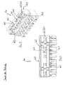
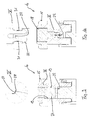
- Fig. 1 to 4 the housing of a socket of the prior art is shown and generally designated by the reference numeral 100.
- the housing 100 initially forms a plug-in opening 101 for receiving a plug-in means, not shown.
- the plug-in opening 101 is formed by two parallel, mutually spaced walls, each supporting a contact spring 102 (contact bearing walls 109).
- Optional end walls 107 connect the contact bearing walls 109.
- the plug-in means to be received by the plug-in opening 101 are usually a plug, a pin header or a plug connector PCB.
- a plurality of contact springs 102 are arranged in series next to each other. These go with not shown mating contacts of a plug means an electrical connection.
- the housing 100 itself is made of an insulating material, usually plastic.
- the contact bearing walls 109 form slot-like recesses 103 for the contact springs 102.
- the contact springs 102 are electrically isolated from one another by means of material webs 104 formed between the recesses 103.
- Cable entry openings 105 are used to connect electrical conductors to the contact springs 102.
- the contact springs 102 are rearward, i. on its side facing away from the plug-in opening insulation displacement contacts, by means of which the contact springs 102 are contacted on inserted into the cable insertion opening 105 conductor.
- socket has various coding. These are first coding walls 106, which are integrally formed integrally with the housing 100 within the insertion opening or as its end wall 107. These extend into the housing 100 at least to the bottom. Further coding means in the form of coding lugs 108 form the housing 100 on the outside.
- the basic idea of the invention relates to any mechanical coding means known from the prior art, for example the coding tabs 108. It is fundamentally advantageous if the coding means of the contact carriers, for example in the form of housing 100 or corresponding plug-in means, on or in these are stored interchangeably. Unless otherwise stated, however, the following description of the drawing refers to coding means in the form of coding walls 106 or their counterpart in the following description of exemplary embodiments according to the invention.
- the prior art according to Fig. 1 and 2 includes three coding walls 106, two of which form the end walls 107 of the housing 100.
- the embodiment of the prior art according to the 3 and 4 only via two Kodierprocess 106, namely designed as an end wall 107 and another mounted in the insertion opening Cod istswand 106.
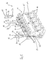
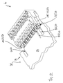
- a contact carrier in the sense of claim 4, the first contact carrier is designated here in the form of a housing of a socket with the reference numeral 10.
- the housing 10 of the socket comprises a made of insulating material, in particular plastic contact carrier 11, which serves a plug-in opening 12 for receiving a plug-in means, not shown, for example, a plug, a pin header or a printed circuit board section.
- the housing 10 according to the invention is also formed by two parallel contact bearing walls 26, which are spaced apart from each other in a gap-forming manner, and possibly by end walls 24.
- Vertical to the insertion opening 12 are cable insertion 13, analogous to the reference numeral 105 of the prior art, formed by the conductor, not shown, are introduced for electrical contacting with stored in the insertion opening 12 contact springs 14.
- cable holder 16 forms. By means of the cable holder 16, the cable ends can be arranged in parallel alignment with the insertion opening 12 on the contact carrier 11.
- the contact carrier 11 of the housing 10 forms externally circumferentially arranged, integrally cohesive Codieran arrangements 15. These correspond with recesses of a complementary plug-in housing and ensure a polarity-safe assembly of socket and plug-in housing.
- 17 coding which are pushed into the insertion opening 12.
- the contact bearing walls 26 within the insertion opening 12 initially in pairs against each other arranged guide grooves 19. These are oriented in the direction of insertion of the plug-in means, not shown, and receive corresponding wall sections 20 of the coding walls 18 for position stabilization.
- the Kodiermond 18 are provided in the insertion direction with locking means 21 which serve the anchorage in the bottom of the plug-in opening 22.
- the plug-in opening 12 is open at its narrow sides 23.
- Specially designed coding walls 18 form end walls 24, by means of which the narrow sides of the plug-in opening 12 can be closed for the purpose of plug coding.
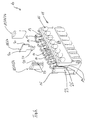
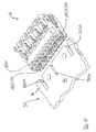
- Figure 6 shows an inventive housing 10 of a socket in a modified embodiment.
- the housing 10 of Fig. 6 has a slightly differently designed in detail contact carrier 11, wherein for the invention, only the differences described below are relevant.
- the depth of the insertion opening 12 in the in Fig. 6 embodiment shown is less than that in Fig. 5 ,
- the serving as the end walls 24 Codiercontent 18 have in contrast to those of Fig. 5 on its lying in the direction of insertion end no locking means. Instead, in the direction of the contact bearing walls 26 facing wall portions 20, the end walls 24 are provided with locking shoulders 27. These engage behind corresponding projections 28 in the guide grooves 19, but in Fig. 6 Not are shown. Due to the smaller depth of the insertion opening 12 and the coding walls 18 are designed to be shorter overall.
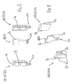
- Fig. 7 are the coding walls 18 according to Fig. 5 shown in Fig. 8 are the coding walls 17 according to Fig. 6 shown. Attention is particularly paid to the coding walls 18 formed as end walls 24 in FIG Fig. 7 to lay. These have material weakening zones 29, against which a shortening section 30 adjoins the insertion direction or at the end facing away from the latching means 21.
- end walls 24 can be used. These are then cut before, during or after assembly by cutting along the material weakening zone 29 around the section 30 (see Fig. 7 ). A similar embodiment of the in Fig. 8 illustrated end walls 24 is conceivable, which then connects a not shown here sectioning section on the insertion opposite end.
- FIGS. 9 and 10 is the housing 10 of the socket according to Fig. 6 shown in a sectional view.
- the section is in the direction of insertion of the end wall 24 in the end wall plane
- in Fig. 10 is the cut in the direction of insertion of the coding wall 18 in the plane.
- Fig. 9 Based on Fig. 9 can the latching of the end wall 24 in the housing 10 according to Fig. 6 clearly recognize.
- the guide grooves 19, in which the end wall 24 is inserted for the purpose of position stabilization, have projections 28 which are latched behind by the shoulders 27. This shows particularly clearly the detail enlargement IX of the Fig. 9 ,
- FIG Fig. 6 The latching behavior of the coding wall 18, which is described in FIG Fig. 6 is shown. Again, this is inserted for the purpose of position stabilization in opposite, introduced into the contact bearing walls 26 guide grooves 19, but the latching takes place through an opening in the bottom 22 of the insertion opening 12. In the region of the opening There are latching projections 31 which are engaged behind in the inserted state of the Kodierstegs 18 of the latch hook 32. This condition is clear in the enlargement X of the Fig. 10 shown.
- a plug-in means 35 in the form of a printed circuit board 34 has a contact zone 36 facing the housing 10 with a multiplicity of conductor tracks, not shown, arranged side by side.
- the contact zone is interrupted by coding means 17 in the form of recesses 37.
- the arrangement is such that the housing 10 can be pushed in only one orientation to the contact zone 36 of the circuit board 34.
- the recesses 37 and coding walls 18 of housing 10 or circuit board 34 in the Fig. 11 and 12 each arranged in different positions.
- the housing 10 of the socket of Fig. 12 on the circuit board 34 of Fig. 11 or the housing of Fig. 11 on the circuit board 34 of Fig. 12 sit up.
- the coding of printed circuit board 34 and housing 10 is not only the polarity-reversible placement at the respective point of the circuit board but also prevents the placement of a housing with different coding.
- a contact carrier 11 has been shown in the form of a housing 10 of a socket, which can be produced as a standard component and the coding is done with coding 17 in the form of Kodierstroken 18 in retrospect.
- this has the decisive advantage that only a few standard components without makeready times can be continuously produced at the production facilities.
- Codiercontent 18 are integrally formed cohesively with the contact carrier 11.
Abstract
Description
Die Erfindung betrifft einen Steckverbinder, mit einem ersten Kontaktträger, in welchem Kontakte angeordnet sind, die mit Gegenkontakten eines zweiten Kontaktträgers bei Anordnung der Kontaktträger aneinander eine elektrische Verbindung eingehen, wobei der erste Kontaktträger erste Kodiermittel umfasst, die mit zweiten Kodiermitteln des zweiten Kontaktträgers zusammenwirken und eine hinsichtlich der Verbindung von Kontakten und Gegenkontakten definierte Anordnung der Kontaktträger aneinander sicherstellen.The invention relates to a connector having a first contact carrier, in which contacts are arranged, which enter into electrical contact with mating contacts of a second contact carrier in the arrangement of the contact carrier, wherein the first contact carrier comprises first coding means, which cooperate with second coding means of the second contact carrier and ensure a defined with respect to the connection of contacts and mating contacts arrangement of the contact carrier to each other.
Ein gattungsgemäßer Steckverbinder ist beispielsweise aus
Bei Steckverbindern gemäß dem Rast 5- oder Rast 2.5-Standard handelt es sich um Steckverbinder, die sich insbesondere bei elektrischen Haus- und Küchengeräten, Heizungssteuerungen und systeminternen Verdrahtungslösungen der Automobilindustrie etabliert haben.Connectors according to the Rast 5 or Rast 2.5 standard are connectors that have become particularly established in electrical household and kitchen appliances, heating controls and intrinsic wiring solutions of the automotive industry.
Solche Steckverbinder umfassen gewöhnlich einen Stecker (zweiter Kontaktträger) und eine Steckbuchse (erster Kontaktträger) in jeweils in der Regel mehrpoliger Auslegung. Der Begriff "Stecker" bezieht sich dabei auf die Ausgestaltung des "männlichen" Kontaktteils, während die "Buchse" "weibliche" Kontaktteile aufweist. Da bei der überwiegenden Anzahl der am Markt eingesetzten RAST-Steckverbinder die Buchse dasjenige Teil ist, welches auf beispielsweise Kontaktabschnitte einer Leiterplatte oder auf eine Stiftleiste aufgesteckt wird, ist die Buchse nachfolgend als Steckbuchse bezeichnet. Folglich werden auch Leiterplatten, Stiftleisten od. dgl. im Sinne der Erfindung als Stecker bzw. Steckmittel angesehen.Such connectors usually comprise a plug (second contact carrier) and a socket (first contact carrier), each in a generally multi-pole design. The term "plug" refers to the design of the "male" contact part, while the "socket" has "female" contact parts. Since most of the RAST connectors used on the market, the socket is that part which is attached to, for example, contact portions of a printed circuit board or a pin header, the socket is hereinafter referred to as a socket. Consequently, printed circuit boards, pin headers od. Like. Considered in the context of the invention as a plug or plug-in means.
Um ein verpolsicheres Zusammensetzen von Steckmittel und Steckbuchse zu gewährleisten, weisen beide Teile Kodiermittel auf. Insbesondere für ein verpolsicheres Ansetzen an Leiterplatten sind die Kodiermittel selbiger als Leiterplattenausnehmungen bzw. Einschnitte im Kontaktbereich der Leiterplatte ausgebildet, die in ihrer Position, Länge und Stärke variieren. Zu jeder Kodierung eines Steckabschnittes einer Leiterplatte wird eine hierzu passende Steckbuchse gefertigt, deren Gehäuse mit den Ausschnitten korrespondierende Kodierwände ausbildet.In order to ensure a polarity-safe assembly of plug-in means and socket, both parts have coding. In particular, for a reverse polarity attachment to printed circuit boards, the coding means selbiger are formed as PCB recesses or cuts in the contact area of the circuit board, which vary in their position, length and thickness. For each coding of a plug-in portion of a printed circuit board, a mating socket is made for this purpose, the housing forms with the cutouts corresponding coding walls.
Ergänzend zu dieser Form der mechanischen Kodierung wird häufig auch eine farbige Kodierung genutzt. Am Steckmittel sind Farbmarkierungen angebracht, die sich in Form von Aufklebern, Farbbalken oder eingefärbten Steckbuchsengehäusen wiederfinden. Somit ist für die Montage kenntlich gemacht ist, dass entsprechend gekennzeichnete Steckbuchsen am Ort identischer Farbe auf das Steckmittel, z.B. die Leiterplatte, aufzusetzen sind. Dabei kann die Farbmarkierung als ergänzende optische, quasi redundante Kodierung zum unverwechselbaren Aneinandersetzen von Steckbuchse und Steckmittel ausgelegt sein oder aber dazu dienen, mechanisch identisch kodierte Steckbuchsen bzw. Steckmittel zur weiteren Unterscheidung zusätzlich zu kodieren.In addition to this form of mechanical coding often a colored coding is used. At the plug-in color markings are mounted, which can be found in the form of stickers, color bars or colored socket housings. Thus, it is made clear for the assembly that correspondingly marked sockets on the location of identical color on the plug means, e.g. the circuit board, are to be put on. In this case, the color marking can be designed as a complementary optical, quasi-redundant coding for unmatched fitting of socket and plug-in means or serve to mechanically coded identical sockets or plug-in means for further distinction in addition.
Die mechanische wie die farbliche Kodierung hat sich als besonders vorteilhaft erwiesen, da eine quasi fehlerfreie Montage - d.h. eine verpolsichere Montage von Steckmittel und Steckbuchse - gewährleistet ist. Mittlerweile wird jedoch die Fertigung derartiger Steckverbinder als verbesserungswürdig angesehen.The mechanical as well as the color coding has proven to be particularly advantageous, since a virtually error-free assembly - i. a reverse polarity safe installation of plug and socket - is guaranteed. Meanwhile, however, the production of such connectors is considered to be in need of improvement.
In der Fertigung werden jeweils Chargen mit einer bestimmten mechanischen und/oder farbigen Kodierung gefertigt, woraufhin dann Rüstzeiten an den Fertigungsanlagen für die Fertigung einer Charge mit anderer mechanischer und/oder farbiger Kodierung notwendig sind. Sofern die Farbkodierung mittels Aufklebern oder Farbbalken erfolgt, ist auch dies ein verbesserungswürdiger Arbeitsschritt.In the production of batches are each made with a specific mechanical and / or color coding, which then set-up times at the manufacturing facilities for the production of a batch with other mechanical and / or color coding are necessary. If the color coding is done by means of stickers or color bars, this too is an improvement step.
Aufgabe der Erfindung ist es, die Fertigung von Steckverbindern mit insbesondere mechanischen Kodiermitteln zu vereinfachen.The object of the invention is to simplify the production of connectors with in particular mechanical coding.
Gelöst wird die Aufgabe von einem Steckverbinder gemäß Anspruch 1, der sich insbesondere dadurch kennzeichnet, dass wenigstens ein Kontaktträger eine Aufnahme für ein als separates Bauteil ausgeführtes Kodiermittel aufweist.The object is achieved by a connector according to claim 1, which is characterized in particular by the fact that at least one contact carrier has a receptacle for an executed as a separate component coding.
Der wesentliche Vorteil der Erfindung liegt darin, dass StandardKontaktträger sowie separat die mechanischem Kodiermittel gefertigt werden können, so dass die Rüstzeiten an den Produktionsanlagen entfallen. Je nach gewünschter mechanischer Kodierung wird aus einem Standardkontaktträger und separaten Kodiermitteln ein Kontaktträger mit entsprechender Kodierung zusammengesetzt.The essential advantage of the invention lies in the fact that standard contact carriers as well as separately the mechanical coding means can be manufactured so that the set-up times at the production plants are eliminated. Depending on the desired mechanical coding, a contact carrier with a corresponding coding is assembled from a standard contact carrier and separate coding means.
Für eine im Wesentlichen unlösbare Anordnung der Kodiermittel ist vorgesehen, dass diese im Kontaktträger verrastbar sind.For a substantially unsolvable arrangement of the coding means is provided that they can be latched in the contact carrier.
Die lagestabile Halterung lässt sich erreichen, indem der Kontaktträger Führungen aufweist, in die die Kodiermittel bereichsweise eingreifen.The storage-stable holder can be achieved by the contact carrier has guides in which the coding engage in areas.
Die Erfindung betrifft insbesondere einen Steckverbinder, dessen erster Kontaktträger ein Gehäuse einer Steckbuchse ist. Dieses ist vorteilhafterweise bodenseitig mit Rastmitteln zur Halterung des Kodiermittels versehen.The invention particularly relates to a connector whose first contact carrier is a housing of a socket. This is advantageously provided on the bottom side with locking means for holding the coding.
Es ist vorgesehen, dass das Kodiermittel für das Gehäuse als einschiebbare Kodierwand ausgebildet ist, wobei insbesondere das Steckbuchsengehäuse hierzu paarweise einander zugeordnete Nuten aufweist, in die Teilbereiche der in das Steckbuchsengehäuse eingeschobenen Kodierwand zwecks Lagestabilisierung eingreifen. Dabei ist es vorteilhaft, wenn die Kodierwand in Einschubrichtung Rastmittel zur Anordnung im Steckbuchsengehäuse aufweist.It is envisaged that the coding means for the housing is designed as a push-in coding wall, wherein in particular the socket housing for this pair has mutually associated grooves, engage in the sub-regions of the inserted into the socket housing coding wall for the purpose of position stabilization. It is advantageous if the coding wall in the insertion direction has latching means for arrangement in the socket housing.
Bei einer besonders bevorzugten Ausführungsform ist die Kodierwand bei seitlich offenem Steckbuchsengehäuse als Stirnwand einsetzbar.In a particularly preferred embodiment, the coding wall can be used as a front wall with the socket housing open at the side.
Da Steckbuchsen mit unterschiedlicher Tiefe bekannt sind, ist vorgesehen, dass die Kodierwand einen über eine Materialschwächungszone angesetzten Kürzungsabschnitt aufweist, um den die Kodierwand bei Einsatz in einem gegenüber seiner Länge weniger tiefen Gehäuse einkürzbar ist.Since sockets are known with different depths, it is provided that the coding wall has a set over a material weakening zone cut section, around which the coding wall can be shortened when used in a less deep compared to its length housing.
Für eine weitere oder alternative Festlegung der Kodierwand ist vorgesehen, dass die Kodierwand an seinen mit dem Gehäuse der Steckbuchse in Berührung stehenden Längsseiten Schultern aufweist, die mit buchsengehäuseseitigen Vorsprüngen eine Rastverbindung eingehen.For a further or alternative definition of the Kodierwand is provided that the Kodierwand has at its standing with the housing of the socket in contact longitudinal sides shoulders, which enter into a snap connection with bushing side projections.
Es ist daran gedacht, diese Form der Rastverbindung insbesondere bei als Stirnwand des Gehäuses eingesetzten Kodierwänden zu verwenden.It is intended to use this form of locking connection, in particular when used as the end wall of the housing Kodierwänden.
Bei dem erfindungsgemäßen Steckverbinder handelt es sich bevorzugt um einen Steckverbinder nach dem Rast 5 bzw. Rast 2.5-Standard.The connector according to the invention is preferably a connector according to the catch 5 or Rast 2.5 standard.
Wenn das Kodiermittel farbig ausgestaltet ist, lässt sich die vorbeschriebene Farbkodierung mittels entsprechend eingefärbter Kodiermittel, insbesondere Kodierwänden vornehmen. So entfallen Rüstzeiten für die Produktion unterschiedlich farbiger Chargen von Kontaktträgern.If the coding means is designed in color, the above-described color coding can be carried out by means of appropriately colored coding means, in particular coding walls. This eliminates set-up times for the production of differently colored batches of contact carriers.
Wenn der erste Kontaktträger als Steckbuchsengehäuse ausgestaltet ist, so ist der zweite Kontaktträger ein Steckmittel, insbesondere ein Stecker oder eine Leiterplatte.If the first contact carrier is designed as a socket housing, then the second contact carrier is a plug-in means, in particular a plug or a printed circuit board.
Weitere Vorteile der Erfindung ergeben sich aus der nachfolgenden Zeichnungsbeschreibung. Es zeigen:
- Fig. 1 und 2
- einen erfindungsgemäßen Kontaktträger in Form eines Gehäuses einer Steckbuchse in Aufsicht bzw. perspektivischer Ansicht mit erster mechanischer Kodierung,
- Fig. 3 und 4
- ein Gehäuse einer Steckbuchse in Aufsicht und perspektivischer Ansicht mit einer zweiten mechanischen Kodierung,
- Fig. 5
- ein Gehäuse einer Steckbuchse eines erfindungsgemäßen Steckverbinders mit Kodierstegen in Explosionsansicht,
- Fig. 6
- das Gehäuse gemäß
Fig. 5 in alternativer Ausführungsform, - Fig. 7
- die Kodierwände gemäß
Fig. 5 , - Fig. 8
- die Kodierwände gemäß
Fig. 6 , - Fig. 9 und 10
- Beispiele für Rastbefestigungen von Kodierwänden in Gehäusen einer Steckbuchse,
- Fig. 11 und 12
- Darstellungen von Steckbuchsen mit voneinander abweichender mechanischer Kodierung zum Aufsatz auf Kontaktabschnitte einer Leiterplatte.
- Fig. 1 and 2
- a contact carrier according to the invention in the form of a housing of a socket in plan view or perspective view with first mechanical coding,
- 3 and 4
- a housing of a socket in plan view and perspective view with a second mechanical coding,
- Fig. 5
- a housing of a socket of a connector according to the invention with Kodierstegen in exploded view,
- Fig. 6
- the housing according to
Fig. 5 in an alternative embodiment, - Fig. 7
- the coding walls according to
Fig. 5 . - Fig. 8
- the coding walls according to
Fig. 6 . - FIGS. 9 and 10
- Examples of locking fixtures of coding walls in housings of a socket,
- FIGS. 11 and 12
- Representations of sockets with different mechanical coding for attachment to contact portions of a circuit board.
In den
Das Gehäuse 100 bildet zunächst eine Stecköffnung 101 zur Aufnahme eines nicht dargestellten Steckmittels aus. Die Stecköffnung 101 wird von zwei parallelen, zueinander beabstandeten Wänden gebildet, die jeweils eine Kontaktfeder 102 lagern (Kontaktlagerwände 109). Optionale Stirnwände 107 verbinden die Kontaktlagerwände 109.The
Bei den von der Stecköffnung 101 aufzunehmenden Steckmitteln handelt es sich zumeist um einen Stecker, eine Stiftleiste oder eine Leiterplatte. Innerhalb der Stecköffnung 101 sind eine Vielzahl von Kontaktfedern 102 in Reihe nebeneinander angeordnet. Diese gehen mit nicht dargestellten Gegenkontakten eines Steckmittels eine elektrische Verbindung ein. Das Gehäuse 100 selbst ist aus einem Isolierstoff, zumeist Kunststoff gefertigt. Die Kontaktlagerwände 109 bilden für die Kontaktfedern 102 schlitzartige Ausnehmungen 103 aus. Die Kontaktfedern 102 sind mittels zwischen den Ausnehmungen 103 gebildeten Materialstegen 104 elektrisch isoliert voneinander beabstandet.The plug-in means to be received by the plug-in
Kabeleinführöffnungen 105 dienen der Anbindung von elektrischen Leitern an die Kontaktfedern 102. Hierzu weisen die Kontaktfedern 102 rückwärtig, d.h. an ihrer der Stecköffnung abgewandten Seite Schneidklemmkontakte auf, mittels derer die Kontaktfedern 102 auf in die Kabeleinführöffnung 105 eingeschobene Leiter kontaktiert werden.
Die in
Grundsätzlich betrifft der Grundgedanke der Erfindung jegliches aus dem Stand der Technik bekannte mechanische Kodiermittel, so beispielsweise auch die Kodiernasen 108. Es ist grundsätzlich von Vorteil, wenn die Kodiermittel der Kontaktträger, beispielsweise in Form von Gehäuse 100 bzw. korrespondierendem Steckmittel, an bzw. in diesen austauschbar gelagert sind. Soweit nicht anders dargestellt, nimmt die folgende Zeichnungsbeschreibung jedoch Bezug auf Kodiermittel in Form von Kodierwänden 106 bzw. deren Pendant in der nachfolgenden Beschreibung erfindungsgemäßer Ausführungsbeispiele.Basically, the basic idea of the invention relates to any mechanical coding means known from the prior art, for example the
Bei der vergleichenden Betrachtung der Ausführungsform aus dem Stand der Technik gemäß
Bezug nehmend auf die
Das Gehäuse 10 der Steckbuchse umfasst einen aus Isolierstoff, insbesondere Kunststoff bestehenden Kontaktträger 11, welcher eine Stecköffnung 12 zur Aufnahme eines nicht dargestellten Steckmittels, beispielsweise eines Steckers, einer Stiftleiste oder eines Leiterplattenabschnitts dient. Wie im Stand der Technik gemäß
Im Mündungsbereich der Stecköffnung 12 bildet der Kontaktträger 11 des Gehäuses 10 außenumfänglich angeordnete, einstückig stoffschlüssige Kodieransätze 15 aus. Diese korrespondieren mit Ausnehmungen eines komplementären Steckmittelgehäuses und gewährleisten ein verpolsicheres Zusammensetzen von Steckbuchsen-und Steckmittelgehäuse.In the mouth region of the plug-in
Von besonderer Bedeutung sind die mit 17 bezeichneten Kodiermittel, welche in die Stecköffnung 12 hineingeschoben werden. Hierzu bilden die Kontaktlagerwände 26 innerhalb der Stecköffnung 12 zunächst paarweise aneinander gegenüber angeordnete Führungsnuten 19 aus. Diese sind in Einschubrichtung des nicht dargestellten Steckmittels orientiert und nehmen korrespondierende Wandabschnitte 20 der Kodierwände 18 zur Lagestabilisierung auf. Die Kodierwände 18 sind in Einschubrichtung mit Rastmitteln 21 versehen, die der Verankerung im Boden der Stecköffnung 22 dienen.Of particular importance are designated with 17 coding, which are pushed into the
Wie aus den
Zunächst ist festzuhalten, dass die Tiefe der Stecköffnung 12 in der in
In
Bei Gehäusen 10 gemäß
In
Anhand der
Anders verhält sich die Verrastung der Kodierwand 18, die in
In den
Zusammenfassend wurde ein Kontaktträger 11 in Form eines Gehäuses 10 einer Steckbuchse dargestellt, welcher als Standardbauteil produziert werden kann und dessen Kodierung mit Kodiermitteln 17 in Form von Kodierwänden 18 im Nachhinein erfolgt. In der Produktion hat dies den entscheidenden Vorteil, dass wenige Standardbauteile ohne Rüstzeiten an den Produktionsanlagen durchgehend gefertigt werden können. Im Gegensatz dazu sind bei der Produktion gattungsgemäßer Steckverbinder im Stand der Technik für jede gewünschte Kodierung die Produktionsanlagen umzurüsten, da dort die innerhalb der Stecköffnung 12 angeordneten Kodierwände 18 einstückig stoffschlüssig mit dem Kontaktträger 11 ausgebildet sind.In summary, a
Darüber hinaus besteht die Möglichkeit, die relativ einfach herzustellenden Kodierwände 18 einzufärben und durch das Einsetzen in ein Gehäuse 10 mit Standardfarbe auch eine Farbkodierung zu realisieren. Die Kodierwände 18 weisen lediglich ein geringes Volumen auf und sind daher auch in größeren Stückzahlen leicht vorhaltbar. Die aufwendigen Rüstzeiten an den Produktionsmaschinen zum Herstellen unterschiedlich eingefärbter Kontaktträger 11 bzw. Gehäuse 10 erübrigt sich. Der erfindungsgemäße Steckverbinder mit Kodiermitteln 17, die als separate Bauteile ausgeführt sind, erlaubt eine wesentlich rationellere Fertigung und Lagerhaltung.In addition, it is possible to color the relatively easy to produce
- 100100
- Gehäuse einer Steckbuchse aus dem Stand der TechnikHousing a socket from the prior art
- 101101
- Stecköffnungplug-in opening
- 102102
- Kontaktfedercontact spring
- 103103
- Ausnehmungrecess
- 104104
- Materialstegmaterial web
- 105105
- Kabeleinführöffnungcable insertion
- 106106
- KodierwandKodierwand
- 107107
- Stirnwand v. 101Front wall v. 101
- 108108
- Kodiernasekeying
- 109109
- KontaktlagerwandContact bearing wall
- 1010
- erfindungsgemäßes Gehäuse einer SteckbuchseInventive housing of a socket
- 1111
- Kontaktträgercontact support
- 1212
- Stecköffnungplug-in opening
- 1313
- Kabeleinführöffnungcable insertion
- 1414
- Kontaktfedercontact spring
- 1515
- KodieransätzeKodieransätze
- 1616
- Kabelhaltercable holder
- 1717
- Kodiermittelcoding
- 1818
- KodierwandKodierwand
- 1919
- Führungsnutenguide
- 2020
- Wandabschnitte von 18Wall sections of 18
- 2121
- Rastmittellatching means
- 2222
- Boden der StecköffnungBottom of the plug-in opening
- 2323
- Schmalseiten von 12Narrow sides of 12
- 2424
- Stirnwändeend walls
- 2525
- Aufnahmeschlitz von 12Recording slot of 12
- 2626
- KontaktlagerwandContact bearing wall
- 2727
- Rastschulternlocking shoulders
- 2828
- Vorsprünge von 19Projections of 19
- 2929
- MaterialschwächungszoneMaterial weakening zone
- 3030
- Kürzungsabschnittreduction section
- 3131
- Rastvorsprüngelatching projections
- 3232
- Rasthakenlatch hook
- 3434
- Leiterplattecircuit board
- 3535
- Steckmittelplug means
- 3636
- Kontaktzonecontact zone
- 3737
- Ausnehmungrecess
Claims (14)
Priority Applications (1)
| Application Number | Priority Date | Filing Date | Title |
|---|---|---|---|
| SI200931150T SI2182592T1 (en) | 2008-10-30 | 2009-08-31 | Connector |
Applications Claiming Priority (1)
| Application Number | Priority Date | Filing Date | Title |
|---|---|---|---|
| DE102008054015A DE102008054015B4 (en) | 2008-10-30 | 2008-10-30 | Connectors |
Publications (3)
| Publication Number | Publication Date |
|---|---|
| EP2182592A2 true EP2182592A2 (en) | 2010-05-05 |
| EP2182592A3 EP2182592A3 (en) | 2012-06-13 |
| EP2182592B1 EP2182592B1 (en) | 2014-12-24 |
Family
ID=41650189
Family Applications (1)
| Application Number | Title | Priority Date | Filing Date |
|---|---|---|---|
| EP09011114.7A Active EP2182592B1 (en) | 2008-10-30 | 2009-08-31 | Connector |
Country Status (5)
| Country | Link |
|---|---|
| US (1) | US7997941B2 (en) |
| EP (1) | EP2182592B1 (en) |
| CN (1) | CN101728718A (en) |
| DE (1) | DE102008054015B4 (en) |
| SI (1) | SI2182592T1 (en) |
Cited By (2)
| Publication number | Priority date | Publication date | Assignee | Title |
|---|---|---|---|---|
| DE102012107298A1 (en) * | 2012-08-09 | 2014-02-13 | Endress + Hauser Flowtec Ag | Attachment element for fixing on plate-shaped element, has corner or projection to limit partial area of outlet opening of channel, where cable is jammed on partial area by tensile load in parallel direction away from plate-shaped element |
| IT202100016016A1 (en) * | 2021-06-18 | 2022-12-18 | Marelli Automotive Lighting Italy S P A Con Socio Unico | ELECTRICAL CONNECTION SYSTEM FOR A VEHICLE HEADLAMP AND ASSOCIATED LIGHTING DEVICE |
Families Citing this family (18)
| Publication number | Priority date | Publication date | Assignee | Title |
|---|---|---|---|---|
| CN102468578B (en) * | 2010-11-16 | 2016-03-16 | 泰科电子(上海)有限公司 | The method for designing of the misplug preventing device of the housing of electric connector |
| DE102011005544A1 (en) * | 2011-03-15 | 2012-09-20 | Robert Bosch Gmbh | Improved multiple direct contacting of electrical components |
| DE202012002501U1 (en) | 2012-03-13 | 2013-06-17 | Lumberg Connect Gmbh | Plug contact for arrangement on a contact carrier |
| DE102012004833A1 (en) * | 2012-03-13 | 2013-09-19 | Lumberg Connect Gmbh | Plug contact for arrangement on a contact carrier |
| DE102012103216A1 (en) * | 2012-04-13 | 2013-10-17 | Wago Verwaltungsgesellschaft Mbh | Connector set and connectors and mating connector this |
| CN102723642A (en) * | 2012-06-29 | 2012-10-10 | 华为技术有限公司 | Golden finger connector and mis-plug prevention device |
| DE102013215787B4 (en) * | 2013-08-09 | 2022-05-05 | Te Connectivity Germany Gmbh | Housing for an electrical connector, kit, connector and connector |
| DE102013108888A1 (en) * | 2013-08-16 | 2015-02-19 | Phoenix Contact Gmbh & Co. Kg | Coding for baseboards with a plurality of chambers |
| DE102013110548A1 (en) * | 2013-09-24 | 2015-03-26 | Phoenix Contact Gmbh & Co. Kg | Connector part with a resistance coding |
| DE102014107948B3 (en) * | 2014-06-05 | 2015-07-30 | Wago Verwaltungsgesellschaft Mbh | Connector assembly and coding element and method for encoding a connector assembly |
| DE202015005042U1 (en) * | 2015-07-14 | 2015-09-09 | Rosenberger Hochfrequenztechnik Gmbh & Co. Kg | Connector assembly with coding |
| DE202016105525U1 (en) | 2016-10-05 | 2018-01-08 | Lumberg Connect Gmbh | Connector with removable coding pins |
| DE102016118870A1 (en) | 2016-10-05 | 2018-04-05 | Lumberg Connect Gmbh | Connector with removable coding pins |
| DE102018101667B3 (en) * | 2018-01-25 | 2019-04-11 | Lumberg Connect Gmbh | Connector with secondary fuse |
| DE102019111164A1 (en) * | 2019-04-30 | 2020-11-05 | Wago Verwaltungsgesellschaft Mbh | Plug connector of an electrical connector and a set of plug connector and functional element |
| JP2020184520A (en) * | 2019-04-30 | 2020-11-12 | ヴァーゴ・フェアヴァルトゥングスゲゼルシャフト・エムベーハー | Connector of electrical connector mechanism and electrical connector mechanism formed thereby |
| DE102021111927B3 (en) | 2021-05-07 | 2022-06-09 | Lumberg Connect Gmbh | connector |
| DE102021213942A1 (en) | 2021-12-08 | 2023-06-15 | BSH Hausgeräte GmbH | Connectors for printed circuit boards or device components |
Citations (1)
| Publication number | Priority date | Publication date | Assignee | Title |
|---|---|---|---|---|
| DE19607381C2 (en) | 1996-02-28 | 2000-06-08 | Lumberg Karl Gmbh & Co | Connectors |
Family Cites Families (25)
| Publication number | Priority date | Publication date | Assignee | Title |
|---|---|---|---|---|
| US3184707A (en) * | 1963-09-23 | 1965-05-18 | Sperry Rand Corp | Universal receptacle shell coding device |
| US3566340A (en) * | 1968-06-14 | 1971-02-23 | Sylvania Electric Prod | Means for polarizing a connector assembly |
| US3573711A (en) * | 1968-11-25 | 1971-04-06 | Amp Inc | Multicontact electrical connector |
| FR2544557B1 (en) * | 1983-04-15 | 1986-05-02 | Telemecanique Electrique | ENCODING DEVICE AND METHOD FOR CONNECTING ELEMENTS IN A PROGRAMMABLE CONTROLLER |
| NO855307L (en) * | 1985-03-28 | 1986-09-29 | Siemens Ag | Code group for building groups that can be inserted into a building group frame. |
| GB8717857D0 (en) * | 1987-07-28 | 1987-09-03 | Amp Great Britain | Keying circuit board edge connector |
| US4986769A (en) * | 1989-11-16 | 1991-01-22 | Amp Incorporated | Polarization and keying mechanism |
| NL9000856A (en) * | 1990-04-11 | 1991-11-01 | Du Pont Nederland | ELECTRICAL CONNECTOR AND COLORED STRIP. |
| US5184961A (en) * | 1991-06-20 | 1993-02-09 | Burndy Corporation | Modular connector frame |
| FR2680052B1 (en) * | 1991-07-30 | 1994-11-04 | Cit Alcatel | ASSOCIATIVE CODING METHOD FOR PRINTED CIRCUIT BOARDS AND DEVICE FOR CARRYING OUT SAID METHOD. |
| FR2699334B1 (en) * | 1992-12-16 | 1995-02-10 | Souriau & Cie | Indexable coding device, and connection device comprising it. |
| US5370556A (en) * | 1993-09-20 | 1994-12-06 | The Whitaker Corporation | Keying system for electrical connectors |
| US5421734A (en) * | 1993-11-03 | 1995-06-06 | Intel Corporation | Method and apparatus for evolving bus from five volt to three point three volt operation |
| US5387132A (en) * | 1993-11-09 | 1995-02-07 | The Whitaker Corporation | Keyed card edge connector |
| DE4420984C2 (en) * | 1994-06-10 | 1998-09-17 | Metz Albert Ria Electronic | Codable connector |
| SG35042A1 (en) * | 1995-01-12 | 1997-02-01 | Ibm | Interchangeable key card edge connecting |
| US6017248A (en) * | 1997-08-28 | 2000-01-25 | Hon Hai Precision Ind. Co., Ltd. | Card edge connector |
| TW431683U (en) * | 1998-10-30 | 2001-04-21 | Hon Hai Prec Ind Co Ltd | Electrical connector |
| DE19964150A1 (en) * | 1999-01-25 | 2000-09-07 | Weidmueller Interface | Encoding device for encoding electrical device has journals and bushes with polygonal or circular shapes aligned according to code system that engage when components are joined |
| JP2001015223A (en) * | 1999-06-25 | 2001-01-19 | Nec Corp | Versatile connector and its coupling method |
| US6716045B2 (en) * | 2001-12-10 | 2004-04-06 | Robinson Nugent, Inc. | Connector with increased creepage |
| DE10301003B3 (en) * | 2003-01-13 | 2004-09-30 | Siemens Ag | Modular installation device |
| DE10301004B3 (en) * | 2003-01-13 | 2004-10-07 | Siemens Ag | Modular installation device |
| DE202006009459U1 (en) * | 2006-06-16 | 2007-10-25 | Weidmüller Interface GmbH & Co. KG | Terminal block with coding device |
| DE102008009350A1 (en) * | 2008-02-14 | 2009-08-20 | Weidmüller Interface GmbH & Co. KG | Plug connection with a coding device and method for mounting the coding device on the plug connection |
-
2008
- 2008-10-30 DE DE102008054015A patent/DE102008054015B4/en active Active
-
2009
- 2009-08-31 EP EP09011114.7A patent/EP2182592B1/en active Active
- 2009-08-31 SI SI200931150T patent/SI2182592T1/en unknown
- 2009-10-28 CN CN200910208121A patent/CN101728718A/en active Pending
- 2009-10-29 US US12/589,886 patent/US7997941B2/en active Active
Patent Citations (1)
| Publication number | Priority date | Publication date | Assignee | Title |
|---|---|---|---|---|
| DE19607381C2 (en) | 1996-02-28 | 2000-06-08 | Lumberg Karl Gmbh & Co | Connectors |
Cited By (3)
| Publication number | Priority date | Publication date | Assignee | Title |
|---|---|---|---|---|
| DE102012107298A1 (en) * | 2012-08-09 | 2014-02-13 | Endress + Hauser Flowtec Ag | Attachment element for fixing on plate-shaped element, has corner or projection to limit partial area of outlet opening of channel, where cable is jammed on partial area by tensile load in parallel direction away from plate-shaped element |
| IT202100016016A1 (en) * | 2021-06-18 | 2022-12-18 | Marelli Automotive Lighting Italy S P A Con Socio Unico | ELECTRICAL CONNECTION SYSTEM FOR A VEHICLE HEADLAMP AND ASSOCIATED LIGHTING DEVICE |
| EP4106112A1 (en) * | 2021-06-18 | 2022-12-21 | Marelli Automotive Lighting Italy S.p.A. Con Socio Unico | Electrical connection system for a vehicle headlight or lamp and associated lighting device |
Also Published As
| Publication number | Publication date |
|---|---|
| EP2182592B1 (en) | 2014-12-24 |
| SI2182592T1 (en) | 2015-04-30 |
| US7997941B2 (en) | 2011-08-16 |
| DE102008054015A1 (en) | 2010-05-06 |
| US20100144206A1 (en) | 2010-06-10 |
| DE102008054015B4 (en) | 2012-11-08 |
| CN101728718A (en) | 2010-06-09 |
| EP2182592A3 (en) | 2012-06-13 |
Similar Documents
| Publication | Publication Date | Title |
|---|---|---|
| EP2182592B1 (en) | Connector | |
| DE102006016882B4 (en) | Connectors | |
| DE10203162B4 (en) | Interconnects | |
| DE102007053722B4 (en) | Hermaphroditic connector | |
| EP2430892A1 (en) | Connection of printed circuit boards | |
| DE10220865A1 (en) | Socket with a holder to be attached to it | |
| DE19916865A1 (en) | Electrical connector box fitting | |
| DE102004011962B4 (en) | Connector terminal, connector and mounting method | |
| DE19949387B4 (en) | Contact part for connection terminal | |
| DE102010010259B4 (en) | Connectors and mating connectors | |
| DE102008055721B4 (en) | Terminal block with busbar, busbar for a terminal block and method for producing such a busbar | |
| EP1575136A2 (en) | Tap device | |
| EP0865105B1 (en) | Female electrical contact with contact spring and use as a terminal contact | |
| DE3014706A1 (en) | CONNECTOR | |
| DE102015217409A1 (en) | Isolation body for a plug-in connection element | |
| DE19724581A1 (en) | Socket for printed circuit boards | |
| DE102010045471A1 (en) | connector device | |
| DE202008014441U1 (en) | Connectors | |
| DE2714158C3 (en) | Connection device for a multi-core round cable | |
| EP1020954B1 (en) | Electric connecting terminal | |
| DE19532623B4 (en) | Electrical plug with an actuating slide | |
| DE102016120304A1 (en) | REMOVED CONNECTORS AND METHOD FOR THE PRODUCTION THEREOF | |
| DE102004018492B3 (en) | Socket for electrically conductive connection with a plug pin, in particular flat pin | |
| EP1094557B1 (en) | PCB high current connecting device | |
| DE102006060620B4 (en) | Connector having a housing with an actuating element and a latching means |
Legal Events
| Date | Code | Title | Description |
|---|---|---|---|
| PUAI | Public reference made under article 153(3) epc to a published international application that has entered the european phase |
Free format text: ORIGINAL CODE: 0009012 |
|
| AK | Designated contracting states |
Kind code of ref document: A2 Designated state(s): AT BE BG CH CY CZ DE DK EE ES FI FR GB GR HR HU IE IS IT LI LT LU LV MC MK MT NL NO PL PT RO SE SI SK SM TR |
|
| AX | Request for extension of the european patent |
Extension state: AL BA RS |
|
| PUAL | Search report despatched |
Free format text: ORIGINAL CODE: 0009013 |
|
| AK | Designated contracting states |
Kind code of ref document: A3 Designated state(s): AT BE BG CH CY CZ DE DK EE ES FI FR GB GR HR HU IE IS IT LI LT LU LV MC MK MT NL NO PL PT RO SE SI SK SM TR |
|
| AX | Request for extension of the european patent |
Extension state: AL BA RS |
|
| RIC1 | Information provided on ipc code assigned before grant |
Ipc: H01R 13/645 20060101AFI20120510BHEP |
|
| 17P | Request for examination filed |
Effective date: 20120808 |
|
| GRAP | Despatch of communication of intention to grant a patent |
Free format text: ORIGINAL CODE: EPIDOSNIGR1 |
|
| INTG | Intention to grant announced |
Effective date: 20140709 |
|
| RIN1 | Information on inventor provided before grant (corrected) |
Inventor name: WIEGEN, SANDRA Inventor name: RENTROP, FRANK Inventor name: PELLIZARI, DIRK Inventor name: PFAFFENBACH, DIRK |
|
| GRAS | Grant fee paid |
Free format text: ORIGINAL CODE: EPIDOSNIGR3 |
|
| RBV | Designated contracting states (corrected) |
Designated state(s): AT BE BG CH CY CZ DK EE ES FI FR GB GR HR HU IE IS IT LI LT LU LV MC MK MT NL NO PL PT RO SE SI SK SM TR |
|
| REG | Reference to a national code |
Ref country code: DE Ref legal event code: R108 |
|
| GRAP | Despatch of communication of intention to grant a patent |
Free format text: ORIGINAL CODE: EPIDOSNIGR1 |
|
| REG | Reference to a national code |
Ref country code: DE Ref legal event code: R108 Effective date: 20141022 |
|
| GRAA | (expected) grant |
Free format text: ORIGINAL CODE: 0009210 |
|
| INTG | Intention to grant announced |
Effective date: 20141105 |
|
| AK | Designated contracting states |
Kind code of ref document: B1 Designated state(s): AT BE BG CH CY CZ DK EE ES FI FR GB GR HR HU IE IS IT LI LT LU LV MC MK MT NL NO PL PT RO SE SI SK SM TR |
|
| REG | Reference to a national code |
Ref country code: GB Ref legal event code: FG4D Free format text: NOT ENGLISH |
|
| REG | Reference to a national code |
Ref country code: CH Ref legal event code: EP |
|
| REG | Reference to a national code |
Ref country code: IE Ref legal event code: FG4D Free format text: LANGUAGE OF EP DOCUMENT: GERMAN |
|
| REG | Reference to a national code |
Ref country code: AT Ref legal event code: REF Ref document number: 703557 Country of ref document: AT Kind code of ref document: T Effective date: 20150115 |
|
| REG | Reference to a national code |
Ref country code: NL Ref legal event code: VDEP Effective date: 20141224 |
|
| PG25 | Lapsed in a contracting state [announced via postgrant information from national office to epo] |
Ref country code: FI Free format text: LAPSE BECAUSE OF FAILURE TO SUBMIT A TRANSLATION OF THE DESCRIPTION OR TO PAY THE FEE WITHIN THE PRESCRIBED TIME-LIMIT Effective date: 20141224 Ref country code: LT Free format text: LAPSE BECAUSE OF FAILURE TO SUBMIT A TRANSLATION OF THE DESCRIPTION OR TO PAY THE FEE WITHIN THE PRESCRIBED TIME-LIMIT Effective date: 20141224 Ref country code: NO Free format text: LAPSE BECAUSE OF FAILURE TO SUBMIT A TRANSLATION OF THE DESCRIPTION OR TO PAY THE FEE WITHIN THE PRESCRIBED TIME-LIMIT Effective date: 20150324 |
|
| REG | Reference to a national code |
Ref country code: LT Ref legal event code: MG4D |
|
| PG25 | Lapsed in a contracting state [announced via postgrant information from national office to epo] |
Ref country code: GR Free format text: LAPSE BECAUSE OF FAILURE TO SUBMIT A TRANSLATION OF THE DESCRIPTION OR TO PAY THE FEE WITHIN THE PRESCRIBED TIME-LIMIT Effective date: 20150325 Ref country code: LV Free format text: LAPSE BECAUSE OF FAILURE TO SUBMIT A TRANSLATION OF THE DESCRIPTION OR TO PAY THE FEE WITHIN THE PRESCRIBED TIME-LIMIT Effective date: 20141224 Ref country code: HR Free format text: LAPSE BECAUSE OF FAILURE TO SUBMIT A TRANSLATION OF THE DESCRIPTION OR TO PAY THE FEE WITHIN THE PRESCRIBED TIME-LIMIT Effective date: 20141224 Ref country code: SE Free format text: LAPSE BECAUSE OF FAILURE TO SUBMIT A TRANSLATION OF THE DESCRIPTION OR TO PAY THE FEE WITHIN THE PRESCRIBED TIME-LIMIT Effective date: 20141224 |
|
| PG25 | Lapsed in a contracting state [announced via postgrant information from national office to epo] |
Ref country code: NL Free format text: LAPSE BECAUSE OF FAILURE TO SUBMIT A TRANSLATION OF THE DESCRIPTION OR TO PAY THE FEE WITHIN THE PRESCRIBED TIME-LIMIT Effective date: 20141224 |
|
| PG25 | Lapsed in a contracting state [announced via postgrant information from national office to epo] |
Ref country code: ES Free format text: LAPSE BECAUSE OF FAILURE TO SUBMIT A TRANSLATION OF THE DESCRIPTION OR TO PAY THE FEE WITHIN THE PRESCRIBED TIME-LIMIT Effective date: 20141224 Ref country code: EE Free format text: LAPSE BECAUSE OF FAILURE TO SUBMIT A TRANSLATION OF THE DESCRIPTION OR TO PAY THE FEE WITHIN THE PRESCRIBED TIME-LIMIT Effective date: 20141224 Ref country code: CZ Free format text: LAPSE BECAUSE OF FAILURE TO SUBMIT A TRANSLATION OF THE DESCRIPTION OR TO PAY THE FEE WITHIN THE PRESCRIBED TIME-LIMIT Effective date: 20141224 Ref country code: SK Free format text: LAPSE BECAUSE OF FAILURE TO SUBMIT A TRANSLATION OF THE DESCRIPTION OR TO PAY THE FEE WITHIN THE PRESCRIBED TIME-LIMIT Effective date: 20141224 Ref country code: RO Free format text: LAPSE BECAUSE OF FAILURE TO SUBMIT A TRANSLATION OF THE DESCRIPTION OR TO PAY THE FEE WITHIN THE PRESCRIBED TIME-LIMIT Effective date: 20141224 |
|
| PG25 | Lapsed in a contracting state [announced via postgrant information from national office to epo] |
Ref country code: IS Free format text: LAPSE BECAUSE OF FAILURE TO SUBMIT A TRANSLATION OF THE DESCRIPTION OR TO PAY THE FEE WITHIN THE PRESCRIBED TIME-LIMIT Effective date: 20150424 Ref country code: PL Free format text: LAPSE BECAUSE OF FAILURE TO SUBMIT A TRANSLATION OF THE DESCRIPTION OR TO PAY THE FEE WITHIN THE PRESCRIBED TIME-LIMIT Effective date: 20141224 |
|
| PG25 | Lapsed in a contracting state [announced via postgrant information from national office to epo] |
Ref country code: DK Free format text: LAPSE BECAUSE OF FAILURE TO SUBMIT A TRANSLATION OF THE DESCRIPTION OR TO PAY THE FEE WITHIN THE PRESCRIBED TIME-LIMIT Effective date: 20141224 |
|
| PLBE | No opposition filed within time limit |
Free format text: ORIGINAL CODE: 0009261 |
|
| STAA | Information on the status of an ep patent application or granted ep patent |
Free format text: STATUS: NO OPPOSITION FILED WITHIN TIME LIMIT |
|
| 26N | No opposition filed |
Effective date: 20150925 |
|
| PG25 | Lapsed in a contracting state [announced via postgrant information from national office to epo] |
Ref country code: MC Free format text: LAPSE BECAUSE OF FAILURE TO SUBMIT A TRANSLATION OF THE DESCRIPTION OR TO PAY THE FEE WITHIN THE PRESCRIBED TIME-LIMIT Effective date: 20141224 Ref country code: LU Free format text: LAPSE BECAUSE OF FAILURE TO SUBMIT A TRANSLATION OF THE DESCRIPTION OR TO PAY THE FEE WITHIN THE PRESCRIBED TIME-LIMIT Effective date: 20150831 |
|
| REG | Reference to a national code |
Ref country code: CH Ref legal event code: PL |
|
| GBPC | Gb: european patent ceased through non-payment of renewal fee |
Effective date: 20150831 |
|
| PG25 | Lapsed in a contracting state [announced via postgrant information from national office to epo] |
Ref country code: CH Free format text: LAPSE BECAUSE OF NON-PAYMENT OF DUE FEES Effective date: 20150831 Ref country code: LI Free format text: LAPSE BECAUSE OF NON-PAYMENT OF DUE FEES Effective date: 20150831 |
|
| REG | Reference to a national code |
Ref country code: IE Ref legal event code: MM4A |
|
| REG | Reference to a national code |
Ref country code: FR Ref legal event code: ST Effective date: 20160429 |
|
| PG25 | Lapsed in a contracting state [announced via postgrant information from national office to epo] |
Ref country code: GB Free format text: LAPSE BECAUSE OF NON-PAYMENT OF DUE FEES Effective date: 20150831 Ref country code: IE Free format text: LAPSE BECAUSE OF NON-PAYMENT OF DUE FEES Effective date: 20150831 |
|
| PG25 | Lapsed in a contracting state [announced via postgrant information from national office to epo] |
Ref country code: FR Free format text: LAPSE BECAUSE OF NON-PAYMENT OF DUE FEES Effective date: 20150831 |
|
| REG | Reference to a national code |
Ref country code: AT Ref legal event code: MM01 Ref document number: 703557 Country of ref document: AT Kind code of ref document: T Effective date: 20150831 |
|
| PG25 | Lapsed in a contracting state [announced via postgrant information from national office to epo] |
Ref country code: AT Free format text: LAPSE BECAUSE OF NON-PAYMENT OF DUE FEES Effective date: 20150831 |
|
| PG25 | Lapsed in a contracting state [announced via postgrant information from national office to epo] |
Ref country code: MT Free format text: LAPSE BECAUSE OF FAILURE TO SUBMIT A TRANSLATION OF THE DESCRIPTION OR TO PAY THE FEE WITHIN THE PRESCRIBED TIME-LIMIT Effective date: 20141224 |
|
| PG25 | Lapsed in a contracting state [announced via postgrant information from national office to epo] |
Ref country code: HU Free format text: LAPSE BECAUSE OF FAILURE TO SUBMIT A TRANSLATION OF THE DESCRIPTION OR TO PAY THE FEE WITHIN THE PRESCRIBED TIME-LIMIT; INVALID AB INITIO Effective date: 20090831 Ref country code: BG Free format text: LAPSE BECAUSE OF FAILURE TO SUBMIT A TRANSLATION OF THE DESCRIPTION OR TO PAY THE FEE WITHIN THE PRESCRIBED TIME-LIMIT Effective date: 20141224 Ref country code: SM Free format text: LAPSE BECAUSE OF FAILURE TO SUBMIT A TRANSLATION OF THE DESCRIPTION OR TO PAY THE FEE WITHIN THE PRESCRIBED TIME-LIMIT Effective date: 20141224 |
|
| PG25 | Lapsed in a contracting state [announced via postgrant information from national office to epo] |
Ref country code: CY Free format text: LAPSE BECAUSE OF FAILURE TO SUBMIT A TRANSLATION OF THE DESCRIPTION OR TO PAY THE FEE WITHIN THE PRESCRIBED TIME-LIMIT Effective date: 20141224 |
|
| PG25 | Lapsed in a contracting state [announced via postgrant information from national office to epo] |
Ref country code: BE Free format text: LAPSE BECAUSE OF NON-PAYMENT OF DUE FEES Effective date: 20150831 |
|
| PG25 | Lapsed in a contracting state [announced via postgrant information from national office to epo] |
Ref country code: MK Free format text: LAPSE BECAUSE OF FAILURE TO SUBMIT A TRANSLATION OF THE DESCRIPTION OR TO PAY THE FEE WITHIN THE PRESCRIBED TIME-LIMIT Effective date: 20141224 |
|
| PG25 | Lapsed in a contracting state [announced via postgrant information from national office to epo] |
Ref country code: PT Free format text: LAPSE BECAUSE OF FAILURE TO SUBMIT A TRANSLATION OF THE DESCRIPTION OR TO PAY THE FEE WITHIN THE PRESCRIBED TIME-LIMIT Effective date: 20141224 |
|
| P01 | Opt-out of the competence of the unified patent court (upc) registered |
Effective date: 20230516 |
|
| P02 | Opt-out of the competence of the unified patent court (upc) changed |
Effective date: 20230518 |
|
| PGFP | Annual fee paid to national office [announced via postgrant information from national office to epo] |
Ref country code: TR Payment date: 20230828 Year of fee payment: 15 Ref country code: IT Payment date: 20230831 Year of fee payment: 15 |
|
| PGFP | Annual fee paid to national office [announced via postgrant information from national office to epo] |
Ref country code: SI Payment date: 20230821 Year of fee payment: 15 |