EP2182309A1 - Arrangement for cooling of an electrical machine - Google Patents
Arrangement for cooling of an electrical machine Download PDFInfo
- Publication number
- EP2182309A1 EP2182309A1 EP08018799A EP08018799A EP2182309A1 EP 2182309 A1 EP2182309 A1 EP 2182309A1 EP 08018799 A EP08018799 A EP 08018799A EP 08018799 A EP08018799 A EP 08018799A EP 2182309 A1 EP2182309 A1 EP 2182309A1
- Authority
- EP
- European Patent Office
- Prior art keywords
- cooling
- heat
- arrangement according
- air
- electrical machine
- Prior art date
- Legal status (The legal status is an assumption and is not a legal conclusion. Google has not performed a legal analysis and makes no representation as to the accuracy of the status listed.)
- Withdrawn
Links
- 238000001816 cooling Methods 0.000 title claims abstract description 37
- 239000002826 coolant Substances 0.000 claims abstract description 21
- 239000003570 air Substances 0.000 claims description 23
- 239000012080 ambient air Substances 0.000 claims description 15
- 239000000110 cooling liquid Substances 0.000 claims description 9
- 238000007906 compression Methods 0.000 claims description 7
- 238000005057 refrigeration Methods 0.000 description 9
- 239000007788 liquid Substances 0.000 description 6
- 238000004804 winding Methods 0.000 description 4
- RYGMFSIKBFXOCR-UHFFFAOYSA-N Copper Chemical compound [Cu] RYGMFSIKBFXOCR-UHFFFAOYSA-N 0.000 description 3
- 229910052802 copper Inorganic materials 0.000 description 3
- 239000010949 copper Substances 0.000 description 3
- 101000849579 Arabidopsis thaliana 30S ribosomal protein S13, chloroplastic Proteins 0.000 description 2
- XEEYBQQBJWHFJM-UHFFFAOYSA-N Iron Chemical compound [Fe] XEEYBQQBJWHFJM-UHFFFAOYSA-N 0.000 description 2
- 239000000498 cooling water Substances 0.000 description 2
- 238000009420 retrofitting Methods 0.000 description 2
- 238000010521 absorption reaction Methods 0.000 description 1
- 230000020169 heat generation Effects 0.000 description 1
- 229910052742 iron Inorganic materials 0.000 description 1
- 239000002245 particle Substances 0.000 description 1
- XLYOFNOQVPJJNP-UHFFFAOYSA-N water Substances O XLYOFNOQVPJJNP-UHFFFAOYSA-N 0.000 description 1
Images
Classifications
-
- F—MECHANICAL ENGINEERING; LIGHTING; HEATING; WEAPONS; BLASTING
- F25—REFRIGERATION OR COOLING; COMBINED HEATING AND REFRIGERATION SYSTEMS; HEAT PUMP SYSTEMS; MANUFACTURE OR STORAGE OF ICE; LIQUEFACTION SOLIDIFICATION OF GASES
- F25D—REFRIGERATORS; COLD ROOMS; ICE-BOXES; COOLING OR FREEZING APPARATUS NOT OTHERWISE PROVIDED FOR
- F25D17/00—Arrangements for circulating cooling fluids; Arrangements for circulating gas, e.g. air, within refrigerated spaces
- F25D17/02—Arrangements for circulating cooling fluids; Arrangements for circulating gas, e.g. air, within refrigerated spaces for circulating liquids, e.g. brine
-
- H—ELECTRICITY
- H02—GENERATION; CONVERSION OR DISTRIBUTION OF ELECTRIC POWER
- H02K—DYNAMO-ELECTRIC MACHINES
- H02K9/00—Arrangements for cooling or ventilating
- H02K9/19—Arrangements for cooling or ventilating for machines with closed casing and closed-circuit cooling using a liquid cooling medium, e.g. oil
-
- Y—GENERAL TAGGING OF NEW TECHNOLOGICAL DEVELOPMENTS; GENERAL TAGGING OF CROSS-SECTIONAL TECHNOLOGIES SPANNING OVER SEVERAL SECTIONS OF THE IPC; TECHNICAL SUBJECTS COVERED BY FORMER USPC CROSS-REFERENCE ART COLLECTIONS [XRACs] AND DIGESTS
- Y02—TECHNOLOGIES OR APPLICATIONS FOR MITIGATION OR ADAPTATION AGAINST CLIMATE CHANGE
- Y02E—REDUCTION OF GREENHOUSE GAS [GHG] EMISSIONS, RELATED TO ENERGY GENERATION, TRANSMISSION OR DISTRIBUTION
- Y02E10/00—Energy generation through renewable energy sources
- Y02E10/70—Wind energy
- Y02E10/72—Wind turbines with rotation axis in wind direction
Definitions
- the invention relates to a cooling-arrangement of an electrical machine.
- the invention relates to a huge electrical machine, which is totally enclosed by a shell or housing.
- One very common cooling-method is the circulation of air or another gaseous medium inside the electrical machine, while the cooling-medium is kept cool by a heat-exchanger.
- This cooling method disadvantageously requires large gas-to-air or gas-to-water heat-exchangers. Furthermore considerable additional power is required to circulate the cooling-medium inside the machine.
- Another cooling-method of a generator which shows a stator and a rotor, is the circulation of a liquid on a first side of the stator. This first side to be cooled is opposite to an air gap, which is between the stator and the rotor.
- the stator shows a number of stacked laminate-plates, which carries metal-windings of stator-coils, so the heat is transferred from the metal-windings through the laminate-plates to the cooling-medium by conduction.
- This cooling method suffers from a considerable temperature-gradient, which exists between the windings of the stator and the cooling-medium - due to a moderate heat-conductivity of the laminate-plates. Because of this it is difficulty to maintain a predetermined winding-temperature, which is below a required maximum-value.
- Another cooling-method is to bring in liquid or gas for cooling-purposes into slots of the laminate-plates, while these slots are used to carry the metal-windings.
- To bring in the cooling-medium hollow ceramic-cooling-pipes are used, which are expensive and difficulty to handle.
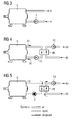
- FIG 3 to FIG 5 shows state-of-the-art arrangements for cooling of a generator G, which may be used inside a nacelle of a wind-turbine.
- the generator G is cooled by normal air A.
- the cooling-air A is forced to flow through the generator G by help of a fan F and is used inside the generator G for cooling-purposes.
- the heated air A is leaving the generator G later.
- the generator G is cooled by air A1, which is forced to flow through the generator G by help of a fan F1.
- ambient air for the cooling as described in FIG 3 as ambient air comprises salt-particles.
- a closed system is used to circulate the cooling-air A1 to and from the generator G, while a heat-exchanger HX is used to hand-over the heat from the cooling air A1 to another cooling-system, which also uses air A2 for the transport of heat.
- the air A2 of this second cooling-system is forced to flow to and from the heat-exchanger HX by help of a fan F2.
- the cooling air A1 is separated from an ambient air A2 by help of the heat exchanger HX, which is a air-to-air heat-exchanger. This results as described in two needed fans F1 and F2.
- the generator G is cooled by a normal liquid LQ.
- the cooling liquid LQ is forced to flow through the generator G by help of a pump P.
- the cooling liquid LQ is cooled by ambient air A3 by help of a heat-exchanger HX, which transfers the heat to circulated ambient air A3.
- the air A3 is forced to flow to and from the heat-exchanger HX by help of a fan F3.
- the benefit of the liquid cooling system as shown in FIG 5 is a higher capacity in intensive cooling of the generator G and furthermore, the generator G is separated from a salty ambient air, comparable to FIG 4 .
- the used cooling-medium as liquid or gas has to show a high speed while passing hot-spots for an efficient cooling. Additionally or alternatively the used cooling-medium has to show a low temperature for an efficient cooling.
- the inventive arrangement for cooling of an electrical machine comprises two cooling-systems as described as follows.
- the electrical machine is connected with a first cooling-system for its direct cooling, while the first cooling-system circulates a first cooling-medium.
- the first cooling-system is connected with a second cooling-system to hand-over heat from the first cooling-system to the second cooling-system.
- the second cooling-system circulates a second cooling-medium to remove the received heat.
- the first cooling-system is connected with a third cooling-system to additionally cool down the first cooling-medium of the first cooling-system.
- the third cooling-system might be any type of refrigeration-system.
- the third cooling-system might be a refrigeration-system of the vapor-compression refrigeration type, which comprises an evaporator.
- the evaporator is used to connect the first and the third cooling-system.
- the third cooling-system might be a compression-cooling-system or an absorption-cooling-system or a magentic-cooling-system or even a Peltier-cooling-system - all of them using their cold "heat sink” to cool down the cooling-medium of the first cooling-system.
- a third cooling-system as described above is brought additionally to an existing cooling-system to enhance the cooling capacity of the whole electrical machine.
- the third system allows to deal with high ambient temperatures. So in this case the third system may be introduced from the beginning or by retrofitting if it is necessary.
- the cooling-arrangement according to the invention allows to cool down active parts, which are located inside the electrical machine, to a temperature that is below the ambient temperature.
- the electrical machine is a generator or motor it is possible to reduce the amount of copper and magnets for a given size of the generator or motor. This leads directly to reduced costs, as copper is an expensive part of the machine.
- the inventive arrangement for cooling might be implemented as additional feature of the generator or motor, which is able to be refitted to already existing machines. So the resulting, whole cooling system of the electrical machine can be adjusted later as an optional solution, which only needs to be applied for hot sites.
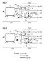
- FIG 1 shows a first embodiment of the inventive cooling-arrangement, which is based on an air-cooled generator G.
- the generator G is located offshore and/or at hot sites in a nacelle of a wind-turbine in a preferred embodiment.
- This first cooling-system CS11 comprises a fan F11 to enforce the flow of cooling-air A11 through the generator G.
- the second cooling system CS12 is connected with the first cooling-system CS11 via an air-to-air heat-exchanger HX11.
- the heat-exchanger HX11 is used to hand-over dissipated heat from the cooling-air A11 to the ambient air A12.
- a third cooling-system CS13 which is a refrigeration-system.
- the third-cooling-system CS13 is connected with the first cooling-system CS11 via an evaporator E if the refrigeration system is a vapor-compression system.
- the third cooling-system CS31 is a vapor-compression system it comprises standard components: the evaporator E, a compressor K, a condenser C and an expansion valve EV.
- the heat is brought to a used cooling-liquid by help of the evaporator E and is brought to the ambient via the air-cooled condenser C.
- Ambient air A13 is forced to flow through the condenser C by help of a fan F13.
- bypass BP which passes parts of the cooling-air A11 over the evaporator E.
- FIG 2 shows a second embodiment of the inventive cooling-arrangement, which is based on a liquid-cooled generator.
- the generator G is located offshore and/or at hot sites in a nacelle of a wind-turbine in a preferred embodiment.
- This first cooling-system CS21 comprises a pump P11 to enforce the flow of a cooling-liquid LQ11 through the generator G.
- the second cooling system CS22 is connected with the first cooling-system CS21 via a liquid-to-air heat-exchanger HX21.
- the heat-exchanger HX21 is used to hand-over dissipated heat from the cooling liquid LQ11 to the ambient air A12.
- a third cooling-system CS23 which is a refrigeration-system.
- the third-cooling-system CS23 is connected with the first cooling-system CS21 via an evaporator E if the refrigeration system is a vapor-compression refrigeration system.
- the third cooling-system CS23 is a vapor-compression refrigeration system, it comprises standard components: the evaporator E, a compressor K, a condenser C and an expansion valve EV.
- the heat is brought to a used cooling-liquid by help of the evaporator E and is brought to the ambient via the air-cooled condenser C.
- Ambient air A13 is forced to flow through the condenser C by help of a fan F31.
- bypass BP which passes parts of the cooling-liquid LQ11 over the evaporator E or over the cold heat sink if other refrigeration systems than vapor-compression systems are used.
- the refrigeration system as described in FIG 1 and FIG 2 are shown as "standard one-step refrigeration system”. It is also possible, to use other types of refrigeration systems like two-step-systems, absorption cooling-systems, etc.
Landscapes
- Engineering & Computer Science (AREA)
- Power Engineering (AREA)
- Chemical & Material Sciences (AREA)
- Combustion & Propulsion (AREA)
- Physics & Mathematics (AREA)
- Mechanical Engineering (AREA)
- Thermal Sciences (AREA)
- General Engineering & Computer Science (AREA)
- Motor Or Generator Cooling System (AREA)
- Cooling Or The Like Of Electrical Apparatus (AREA)
Priority Applications (6)
| Application Number | Priority Date | Filing Date | Title |
|---|---|---|---|
| EP08018799A EP2182309A1 (en) | 2008-10-28 | 2008-10-28 | Arrangement for cooling of an electrical machine |
| NZ580108A NZ580108A (en) | 2008-10-28 | 2009-10-01 | A cooling system for cooling an electrical generator located inside a nacelle of a wind-turbine |
| CA2683486A CA2683486A1 (en) | 2008-10-28 | 2009-10-26 | Arrangement for cooling of an electrical machine |
| US12/606,363 US8453473B2 (en) | 2008-10-28 | 2009-10-27 | Arrangement for cooling of an electrical machine |
| JP2009247150A JP2010107192A (ja) | 2008-10-28 | 2009-10-28 | 電気機械の冷却装置 |
| CN200910208134A CN101728896A (zh) | 2008-10-28 | 2009-10-28 | 用于冷却电机的装置 |
Applications Claiming Priority (1)
| Application Number | Priority Date | Filing Date | Title |
|---|---|---|---|
| EP08018799A EP2182309A1 (en) | 2008-10-28 | 2008-10-28 | Arrangement for cooling of an electrical machine |
Publications (1)
| Publication Number | Publication Date |
|---|---|
| EP2182309A1 true EP2182309A1 (en) | 2010-05-05 |
Family
ID=40636967
Family Applications (1)
| Application Number | Title | Priority Date | Filing Date |
|---|---|---|---|
| EP08018799A Withdrawn EP2182309A1 (en) | 2008-10-28 | 2008-10-28 | Arrangement for cooling of an electrical machine |
Country Status (6)
| Country | Link |
|---|---|
| US (1) | US8453473B2 (enExample) |
| EP (1) | EP2182309A1 (enExample) |
| JP (1) | JP2010107192A (enExample) |
| CN (1) | CN101728896A (enExample) |
| CA (1) | CA2683486A1 (enExample) |
| NZ (1) | NZ580108A (enExample) |
Cited By (2)
| Publication number | Priority date | Publication date | Assignee | Title |
|---|---|---|---|---|
| US9133826B2 (en) | 2011-05-06 | 2015-09-15 | Siemens Aktiengesellschaft | Cooling arrangement of a wind turbine |
| EP3716452A1 (en) * | 2019-03-28 | 2020-09-30 | Sumitomo Heavy Industries, Ltd. | Actuator for mounting on injection molding machine, actuator cooling device, injection molding machine, and method for using actuator cooling device |
Families Citing this family (14)
| Publication number | Priority date | Publication date | Assignee | Title |
|---|---|---|---|---|
| US8978395B2 (en) | 2010-08-18 | 2015-03-17 | Remy Technologies, L.L.C. | Reject heat driven absorption cooling cycle |
| CN102035307B (zh) * | 2010-12-29 | 2012-07-04 | 哈尔滨电机厂有限责任公司 | 具有主副冷凝器的水轮发电机蒸发冷却系统 |
| CN102290920A (zh) * | 2011-08-22 | 2011-12-21 | 安徽汇展热交换系统有限公司 | 一种分体式散热器结构 |
| EP2882961A1 (en) * | 2012-08-10 | 2015-06-17 | youWINenergy GmbH | Integrated cooling system for a nacelle of a wind turbine |
| CN104566852B (zh) * | 2014-12-15 | 2017-02-22 | 珠海格力电器股份有限公司 | 空调器及空调器的电机冷却方法 |
| CN104979960A (zh) * | 2015-07-14 | 2015-10-14 | 国家电网公司 | 一种发电电动机的外蒸发式冷却系统 |
| CN108512340A (zh) * | 2018-01-24 | 2018-09-07 | 汇源印刷包装科技(天津)股份有限公司 | 一种印刷机物流系统用电机 |
| EP3518399B1 (en) | 2018-01-30 | 2020-09-30 | Siemens Gamesa Renewable Energy A/S | A cooling system for a superconducting generator |
| CN109088504B (zh) * | 2018-09-21 | 2024-05-17 | 常州明磁卓控智能科技有限公司 | 一种高散热性能的磁悬浮电机装置 |
| CN110492675A (zh) * | 2019-07-05 | 2019-11-22 | 中国科学院电工研究所 | 用于电机的蒸发式冷却系统 |
| EP3828411B1 (en) | 2019-11-27 | 2023-08-02 | Siemens Gamesa Renewable Energy A/S | Wind turbine and method for operating the wind turbine |
| CN111120018B (zh) * | 2020-01-19 | 2020-11-10 | 徐州法若成制造有限公司 | 一种用于机械的冷却循环装置 |
| CN115102329B (zh) * | 2022-08-24 | 2022-11-18 | 杭州重红科技有限公司 | 一种新能源电机降温装置 |
| CN117175859B (zh) * | 2023-11-03 | 2024-02-23 | 山东华立供水设备有限公司 | 一种用于清水泵的永磁同步电机 |
Citations (4)
| Publication number | Priority date | Publication date | Assignee | Title |
|---|---|---|---|---|
| JPH10300265A (ja) * | 1997-05-01 | 1998-11-13 | Daikin Ind Ltd | 冷凍装置 |
| US5974817A (en) * | 1997-09-15 | 1999-11-02 | Technotrans Ag | Assembly for controlling the temperature of a fountain fluid and/or selected rollers of a printing machine |
| US6330809B1 (en) | 2000-12-08 | 2001-12-18 | General Electric Company | Application of a chiller in an apparatus for cooling a generator/motor |
| US20050150410A1 (en) * | 2003-11-21 | 2005-07-14 | Technotrans Ag | Tempering device for printing presses |
Family Cites Families (3)
| Publication number | Priority date | Publication date | Assignee | Title |
|---|---|---|---|---|
| JPH062569A (ja) * | 1992-06-17 | 1994-01-11 | Hitachi Ltd | ガスタービン発電設備の多目的冷却方法 |
| JP3522658B2 (ja) * | 2000-06-23 | 2004-04-26 | オリオン機械株式会社 | 冷却システムの制御方法 |
| JP4273727B2 (ja) * | 2002-09-06 | 2009-06-03 | ダイキン工業株式会社 | 冷凍システム |
-
2008
- 2008-10-28 EP EP08018799A patent/EP2182309A1/en not_active Withdrawn
-
2009
- 2009-10-01 NZ NZ580108A patent/NZ580108A/en not_active IP Right Cessation
- 2009-10-26 CA CA2683486A patent/CA2683486A1/en not_active Abandoned
- 2009-10-27 US US12/606,363 patent/US8453473B2/en not_active Expired - Fee Related
- 2009-10-28 JP JP2009247150A patent/JP2010107192A/ja active Pending
- 2009-10-28 CN CN200910208134A patent/CN101728896A/zh active Pending
Patent Citations (4)
| Publication number | Priority date | Publication date | Assignee | Title |
|---|---|---|---|---|
| JPH10300265A (ja) * | 1997-05-01 | 1998-11-13 | Daikin Ind Ltd | 冷凍装置 |
| US5974817A (en) * | 1997-09-15 | 1999-11-02 | Technotrans Ag | Assembly for controlling the temperature of a fountain fluid and/or selected rollers of a printing machine |
| US6330809B1 (en) | 2000-12-08 | 2001-12-18 | General Electric Company | Application of a chiller in an apparatus for cooling a generator/motor |
| US20050150410A1 (en) * | 2003-11-21 | 2005-07-14 | Technotrans Ag | Tempering device for printing presses |
Cited By (2)
| Publication number | Priority date | Publication date | Assignee | Title |
|---|---|---|---|---|
| US9133826B2 (en) | 2011-05-06 | 2015-09-15 | Siemens Aktiengesellschaft | Cooling arrangement of a wind turbine |
| EP3716452A1 (en) * | 2019-03-28 | 2020-09-30 | Sumitomo Heavy Industries, Ltd. | Actuator for mounting on injection molding machine, actuator cooling device, injection molding machine, and method for using actuator cooling device |
Also Published As
| Publication number | Publication date |
|---|---|
| NZ580108A (en) | 2010-09-30 |
| CN101728896A (zh) | 2010-06-09 |
| JP2010107192A (ja) | 2010-05-13 |
| CA2683486A1 (en) | 2010-04-28 |
| US20100102653A1 (en) | 2010-04-29 |
| US8453473B2 (en) | 2013-06-04 |
Similar Documents
| Publication | Publication Date | Title |
|---|---|---|
| EP2182309A1 (en) | Arrangement for cooling of an electrical machine | |
| EP2182619B1 (en) | Arrangement for cooling of an electrical machine | |
| JP2010107192A6 (ja) | 電気機械の冷却装置 | |
| KR102706248B1 (ko) | 차량용 열관리시스템 | |
| TWI500244B (zh) | 冷卻回路、致冷系統及用以冷卻壓縮機馬達之方法 | |
| JP5692985B2 (ja) | 電気機械の冷却のための装置 | |
| JP2005353410A (ja) | 燃料電池用冷却装置及びそれを搭載した車両 | |
| NZ579620A (en) | Cooling of an electrical machine by using an internal heat exchanger to isolate the machine from ambient air | |
| JP4267373B2 (ja) | 車両用電動機冷却システム | |
| Shewalkar et al. | Review on cooling techniques and analysis methods of an electric vehicle motor | |
| JP2013193632A (ja) | 冷却システム | |
| CN104467287A (zh) | 具有闭合回路空气冷却的电机 | |
| Geng et al. | Design of cooling system for high torque density permanent magnet synchronous motor based on heat pipe | |
| KR100899269B1 (ko) | 연료전지 자동차의 열관리시스템 | |
| JPH11341740A (ja) | 発電プラントの冷却装置および冷却方法 | |
| KR200382399Y1 (ko) | 냉동사이클을 적용한 발전기·전동기 고정자 냉각장치 | |
| US12283873B2 (en) | Method and system for pole retainer with integrated cooling | |
| CN221300054U (zh) | 一种风电机组齿轮箱的两相流体散热系统 | |
| CN223552596U (zh) | 一种散热系统及储能一体机 | |
| JP2014129905A (ja) | 冷凍装置 | |
| RU182990U1 (ru) | Электрическая машина | |
| KR200382400Y1 (ko) | 냉동사이클을 적용한 발전기·전동기 프레임 냉각장치 | |
| CN121078690A (zh) | 一种基于斯特林发动机的数据中心散热装置 | |
| KR20240077473A (ko) | 냉각장치를 가지는 중전기기 | |
| EP2747253A1 (en) | Arrangement for cooling a turbo generator and a method therefore |
Legal Events
| Date | Code | Title | Description |
|---|---|---|---|
| PUAI | Public reference made under article 153(3) epc to a published international application that has entered the european phase |
Free format text: ORIGINAL CODE: 0009012 |
|
| AK | Designated contracting states |
Kind code of ref document: A1 Designated state(s): AT BE BG CH CY CZ DE DK EE ES FI FR GB GR HR HU IE IS IT LI LT LU LV MC MT NL NO PL PT RO SE SI SK TR |
|
| AX | Request for extension of the european patent |
Extension state: AL BA MK RS |
|
| 17P | Request for examination filed |
Effective date: 20100921 |
|
| 17Q | First examination report despatched |
Effective date: 20101020 |
|
| AKX | Designation fees paid |
Designated state(s): AT BE BG CH CY CZ DE DK EE ES FI FR GB GR HR HU IE IS IT LI LT LU LV MC MT NL NO PL PT RO SE SI SK TR |
|
| RAP1 | Party data changed (applicant data changed or rights of an application transferred) |
Owner name: SIEMENS AKTIENGESELLSCHAFT |
|
| RAP1 | Party data changed (applicant data changed or rights of an application transferred) |
Owner name: SIEMENS AKTIENGESELLSCHAFT |
|
| STAA | Information on the status of an ep patent application or granted ep patent |
Free format text: STATUS: THE APPLICATION IS DEEMED TO BE WITHDRAWN |
|
| 18D | Application deemed to be withdrawn |
Effective date: 20180501 |