EP2182297B1 - Verfahren und Vorrichtung zur wärmebedarfsgeführten Adaption der Vorlauftemperatur einer Heizungsanlage - Google Patents
Verfahren und Vorrichtung zur wärmebedarfsgeführten Adaption der Vorlauftemperatur einer Heizungsanlage Download PDFInfo
- Publication number
- EP2182297B1 EP2182297B1 EP09174101.7A EP09174101A EP2182297B1 EP 2182297 B1 EP2182297 B1 EP 2182297B1 EP 09174101 A EP09174101 A EP 09174101A EP 2182297 B1 EP2182297 B1 EP 2182297B1
- Authority
- EP
- European Patent Office
- Prior art keywords
- temperature
- heat
- heating
- supply temperature
- flow
- Prior art date
- Legal status (The legal status is an assumption and is not a legal conclusion. Google has not performed a legal analysis and makes no representation as to the accuracy of the status listed.)
- Active
Links
- 238000010438 heat treatment Methods 0.000 title claims description 159
- 238000000034 method Methods 0.000 title claims description 48
- 230000008859 change Effects 0.000 claims description 24
- 230000003247 decreasing effect Effects 0.000 claims description 13
- 230000007423 decrease Effects 0.000 claims description 11
- 238000006243 chemical reaction Methods 0.000 claims description 5
- 230000000630 rising effect Effects 0.000 claims description 4
- 230000000694 effects Effects 0.000 claims description 2
- 238000012544 monitoring process Methods 0.000 claims 1
- 230000009467 reduction Effects 0.000 description 25
- 230000006978 adaptation Effects 0.000 description 11
- 238000011156 evaluation Methods 0.000 description 8
- 238000013461 design Methods 0.000 description 7
- 238000004364 calculation method Methods 0.000 description 6
- 230000033228 biological regulation Effects 0.000 description 4
- 230000003750 conditioning effect Effects 0.000 description 4
- 238000012937 correction Methods 0.000 description 4
- 238000001514 detection method Methods 0.000 description 4
- 230000003044 adaptive effect Effects 0.000 description 3
- 238000004891 communication Methods 0.000 description 3
- 230000001276 controlling effect Effects 0.000 description 3
- 238000001816 cooling Methods 0.000 description 3
- 238000010586 diagram Methods 0.000 description 3
- 238000005070 sampling Methods 0.000 description 3
- 238000011217 control strategy Methods 0.000 description 2
- 238000011161 development Methods 0.000 description 2
- 238000005265 energy consumption Methods 0.000 description 2
- 238000005259 measurement Methods 0.000 description 2
- 230000007704 transition Effects 0.000 description 2
- 238000004458 analytical method Methods 0.000 description 1
- 238000013459 approach Methods 0.000 description 1
- 230000008094 contradictory effect Effects 0.000 description 1
- 239000002826 coolant Substances 0.000 description 1
- 238000006073 displacement reaction Methods 0.000 description 1
- 238000005516 engineering process Methods 0.000 description 1
- 239000000446 fuel Substances 0.000 description 1
- 230000017525 heat dissipation Effects 0.000 description 1
- 238000009434 installation Methods 0.000 description 1
- 238000011835 investigation Methods 0.000 description 1
- XULSCZPZVQIMFM-IPZQJPLYSA-N odevixibat Chemical compound C12=CC(SC)=C(OCC(=O)N[C@@H](C(=O)N[C@@H](CC)C(O)=O)C=3C=CC(O)=CC=3)C=C2S(=O)(=O)NC(CCCC)(CCCC)CN1C1=CC=CC=C1 XULSCZPZVQIMFM-IPZQJPLYSA-N 0.000 description 1
- 238000013021 overheating Methods 0.000 description 1
- 230000008569 process Effects 0.000 description 1
- 230000001105 regulatory effect Effects 0.000 description 1
- 238000011160 research Methods 0.000 description 1
- 230000004044 response Effects 0.000 description 1
- 238000012552 review Methods 0.000 description 1
- 230000007480 spreading Effects 0.000 description 1
- 238000010972 statistical evaluation Methods 0.000 description 1
- 230000009897 systematic effect Effects 0.000 description 1
- XLYOFNOQVPJJNP-UHFFFAOYSA-N water Substances O XLYOFNOQVPJJNP-UHFFFAOYSA-N 0.000 description 1
Images


Classifications
-
- F—MECHANICAL ENGINEERING; LIGHTING; HEATING; WEAPONS; BLASTING
- F24—HEATING; RANGES; VENTILATING
- F24D—DOMESTIC- OR SPACE-HEATING SYSTEMS, e.g. CENTRAL HEATING SYSTEMS; DOMESTIC HOT-WATER SUPPLY SYSTEMS; ELEMENTS OR COMPONENTS THEREFOR
- F24D19/00—Details
- F24D19/10—Arrangement or mounting of control or safety devices
- F24D19/1006—Arrangement or mounting of control or safety devices for water heating systems
- F24D19/1009—Arrangement or mounting of control or safety devices for water heating systems for central heating
- F24D19/1048—Counting of energy consumption
-
- G—PHYSICS
- G05—CONTROLLING; REGULATING
- G05D—SYSTEMS FOR CONTROLLING OR REGULATING NON-ELECTRIC VARIABLES
- G05D23/00—Control of temperature
- G05D23/19—Control of temperature characterised by the use of electric means
- G05D23/1919—Control of temperature characterised by the use of electric means characterised by the type of controller
Definitions
- the mass flow through the entire heating system or individual heating circuits of the heating system and the associated return temperature of the entire heating system or the heating system measured individual heating circuits. From these measurements, a heat demand trend is determined, based on which the flow temperature of the heating system and / or the individual heating circuits is specified by reacting with increasing heat demand with a rising flow temperature and with falling heat demand with a decreasing flow temperature.
- the setpoint of the flow temperature of the heating medium is guided in dependence on the outside temperature according to the specifications of a stationary heating curve, as in Fig. 1 is shown for different heating curve types, which differ only marginally. Thereafter, as the outside temperature decreases, the set point of the heating medium flow temperature increases to take into account the increased heat demand at low outside temperatures.
- heating systems and heating controls for controlling the heating system have already been proposed which use information from the building to determine the actual heat demand of the building and to adjust the flow temperature to this actual heat demand.
- the EP 0 260 343 B1 describes a method and a device for controlling the temperature of heating and cooling systems, according to which the target temperature of a heat or cold source depending on a presumed as a priori known outside temperature and, for example, the room air temperature is performed as another measured reference temperature. There is an evaluation of the heating and cooling rate of the heating or cooling medium in order to make a further correction of the desired value of the heat or cold source.
- FIG. 2 This principle of the underlying principle of the present invention control method is in relation to Fig. 2 explains in more detail what a block diagram a heat demand trend controller with the individual modules signal conditioning 1, fuzzy controller 2 and setpoint calculation 3 represents.
- Input variables are the measured, for example, in a heat meter mass flow or flow m and the return temperature ⁇ RL the heating system or a heating circuit. From these quantities, a low-pass filtered mass flow ⁇ TP is determined in the signal conditioning 1, which is then sampled with a certain sampling time. Differencing between two consecutive samples provides the mass current trend ⁇ TEND . Further, the difference formed from a flow temperature setpoint ⁇ VLSoll and the return temperature ⁇ RL is low-pass filtered and sampled in a certain sampling time.
- the difference between two successive samples corresponds to the spread tendency ⁇ ⁇ TEND , which indicates whether the spread between two sampling steps has risen, fallen or is unchanged.
- These values are evaluated by means of fuzzy logic in the fuzzy controller 2 to determine the heat demand tendency Q ⁇ TEND which is supplied to a target value calculation 3 of the heat demand tendency controller to determine the flow temperature ⁇ VL which is used to determine If necessary, the desired flow temperature ⁇ VLSoll obtained from the heating run curve is corrected by reacting with increasing heat demand with an increasing flow temperature ⁇ VL and with decreasing heat requirement with a decreasing flow temperature ⁇ VL .
- the problem that only respond to changes in heat demand and the absolute level of heat demand can not be determined. This can lead to an excessive lowering of the flow temperature ⁇ VL and thus to discomfort conditions.
- the DE 10 2006 013 098 B3 describes a method and a device for on-demand heat supply in a heating system, depending on an external reference variable, a predetermined heat output provided.
- the heat output provided additionally depends on the heat demand of the heating system, in that, in the case of dependence on the external reference variable, correction values are taken into account, which are determined as a function of the external reference variable from a correction curve.
- the object of the present invention is therefore to avoid discomfort conditions in the control method of the type mentioned at the outset by lowering the flow temperature too far.
- the invention proposes that in the case of a decreasing flow temperature, a lowering limit is determined by which the flow temperature is lowered to a maximum.
- the Absenkgrenze is specified as a constant.
- a maximum lowering temperature for the flow temperature at about 6 K can be specified by which the flow temperature is lowered from a controlled state. With reasonably adjusted heating, this does not lead to any significant loss of comfort, even if the reduction is greater than would be appropriate for the heating situation. After too much reduction, the system tends to detect an increasing demand for heat and counteract the excessive lowering.
- An alternative, also useful constant lowering limit can be due to a firmly defined maximum undershooting of the predetermined by the outside temperature or weather-compensated control flow temperature. Also in this case, a meaningful constant lowering limit in the sense of falling below the predetermined by the Schuungsfahrkurve flow temperature value between 5 to 10 K, which offers a balance between energy savings on the other hand and achieved comfort on the other hand. If appropriate, a "constant" lowering limit can also be guided in the course of the outdoor temperature or defined relative to the flow temperature value predetermined by the heating travel curve.
- a better heat adaptation can be achieved according to the invention by detecting and evaluating a change in the measured quantity mass flow, return temperature and / or variables derived therefrom after a change in the flow temperature in order to determine the lowering limit of the flow temperature.
- the mass flow and the return temperature in a heating circuit or the entire heating system and derived variables allow, at a flow temperature change to meet expectations of a reaction of these variables as a function of the heat demand of the heating system.
- rules for an expected behavior in certain states of the heating system can be specified and compared with the actual measured values. This allows reliable statements as to whether the flow temperature has been lowered beyond a reasonable lowering limit so that such a reduction can be counteracted before discomfort conditions occur in a heated building. It is also possible to evaluate a combination of a plurality of measured variables and, if appropriate, variables derived therefrom, which can offer more reliable statements than single measured values by a joint analysis.
- the ratio of the current mass flow and a nominal mass flow and / or the ratio of the current heat output and an expected heat output can be evaluated to determine the lowering limit of the flow temperature.
- the nominal mass flow can be determined, for example, in a trailing pointer principle by storing the largest prevailing mass flow in the heating system or the heating circuit.
- the nominal mass flow determined in the "toe-pointing" principle may preferably be determined in a sliding manner over a period of about one month.
- the current heat output can be read from a heat meter, which measures the parameters flow temperature, return temperature and mass flow.
- the expected heat output results from the rated heater power, which is known as the sum of the rated heater power installed in the heating system and applies to the design room temperature and the design outdoor temperature. By measuring the current outside temperature, which is at an outdoor temperature Heating control is already known, and measurement or estimation of the current room temperature can thus be concluded on the expected heat output.
- the ratio of current mass flow to nominal mass flow or current heat output to expected heat output provides a good indication for determining the lowering limit of the flow temperature, also independent of observation of the change over time of the measured quantities mass flow and return temperature.
- the reliability in determining the lowering limit can be further improved.
- the proposed method by evaluating the time course of the mass flow and / or the power lowering times of the flow temperature of the heating system, for example on the boiler itself and / or a typical user behavior can be detected. From this, an increasing or decreasing heat requirement can be predicted in terms of time prediction, even before the detection of thermal tendencies can be applied to realize a heat-adaptive control. If the predicative heat tendencies do not coincide with the real heat trends, the influencing of the heating system predefined by the predicative flow temperature change is corrected by the detection of contradictory thermal tendencies in the real system.
- the invention proposes not to consider inactive radiators in the adaptation of the flow temperature.
- radiators whose valves are completely closed are not taken into account.
- these data are immediately available.
- Such a procedure is also suitable for in the EP 1 456 727 B1 or the EP 1 645 928 A1 described heat demand control of the flow temperature by characteristic-based determination of supply conditions due to valve positions or data of the heat cost allocators.
- electronic heating cost allocators such as radio heat cost allocators, which are attached to the radiator, can be used in particular to infer the activity of the radiators from the measured radiator overtemperature and / or the measured or derived room air temperature. For this purpose, it can be determined whether the room temperature and / or a radiator overtemperature is below a predetermined limit. Furthermore, in the region of the limit value, a sliding transition between an active and an inactive heating surface can take place by means of weighting factors.
- the inventively proposed method for heat demand-guided adaptation of the flow temperature of a heating system, as described above, according to the invention is also suitable for use in a on the determination of supply conditions based heat adaptation control, as described in the EP 1 456 727 B1 or EP 1 645 928 A1 is described.
- an overall supply state of a heating system which is determined from individual heating surface supply states, on the basis of the ascertained increasing or decreasing heat demand, ie the heat demand trend, to be checked.
- the individual heating surface supply states are determined by means of characteristic curves on the basis of the data obtained by electronic heat cost allocators or due to radiator valve positions and made plausible by the knowledge obtained with the method described above.
- the review of the overall supply state based on the mass flow, the return temperature or can be done by a heat meter with measured flow temperature.
- information about inactive heating surface and / or specific user profiles can be used.
- the data obtained can also be used to determine the overall supply conditions better and faster, in particular by an active flow temperature correction.
- the invention also relates to a device for heat demand guided adaptation of preferably outside temperature-controlled flow temperature of a heating system according to the features of claim 9 with a measuring device for measuring the mass flow through the entire heating system or individual heating circuits in the heating system and the associated return temperature also the entire heating system or individual heating circuits.
- a computing device is provided, which is adapted to determine from these measures a heat demand trend and to specify based on the flow temperature of the heating system and / or the individual heating circuits by with increasing heat demand with a rising flow temperature and with decreasing heat demand with a falling flow temperature is reacted.
- the arithmetic unit determines a lowering limit by which the flow temperature is maximally lowered.
- the measuring device may simply be a heat meter integrated in the heating system, which is often provided in heating systems anyway.
- an outside temperature sensor is preferably connected to the device, and the computing device is set up to determine a flow temperature for the heating system on the basis of an outside temperature-controlled heating characteristic as a function of the current heat requirement.
- the flow temperature given by the heating run curve or heating curve as a heating characteristic provides a very good approximation to the actual heat requirement and can be adapted to the actual heat requirement by determining a heat demand trend, whereby according to the invention a lowering limit oriented on the heat demand is determined.
- the invention is based on the input with reference to Fig. 2 already presented tendencies method for determining the change in heat demand using a measured in particular by a heat meter mass flow m and a return temperature ⁇ RL , wherein the total flow temperature ⁇ VL can be used as an input variable.
- the heat demand trend Q ⁇ TEND obtained from these measured quantities via a signal conditioning 1 and a fuzzy control 2 is used to increase the flow temperature ⁇ VL as the heat requirement increases and to lower it as the heat demand decreases.
- the parameter of the flow temperature adjustment ie a lowering limit by which the flow temperature is lowered to the maximum, derived solely from the data of the heat meter by criteria for the detection of discomfort conditions to be avoided are specified.
- the actual heat requirement of the building is determined from the information that the heat meter provides about the current system status, ie the ⁇ VL , the return temperature ⁇ RL and the mass or volume flow ( ⁇ or v). Depending on the actual heat requirement, the flow temperature ⁇ VL can then be corrected.
- a heat demanded component which is determined as a function of the current heat demand trend Q ⁇ TEND .
- the change in the mass flow ⁇ can be evaluated after a change in the flow temperature ⁇ VL in order to determine the lowering limit.
- the flow temperature ⁇ VL is raised by a certain temperature jump and the subsequent change in the mass flow ⁇ evaluated.
- the temperature jump may be on the order of about 5 K, which is usually capable of causing changes in the system without these changes being immediately felt by the user.
- the mass flow ⁇ remains unchanged, there is no throttling of the flow through the thermostatic valves.
- the heat energy additionally provided by the flow temperature increase is consumed, ie the total number of radiators was in an undersupplied state before the flow temperature ⁇ VL was increased. A flow temperature lowering can not be done in this case.
- the flow temperature ⁇ VL can be determined at which the thermostatic valves begin to throttle the flow. In this state, a heat input corresponding flow temperature ⁇ VL the heating system was set. This value represents the lowering limit for a flow temperature reduction.
- the ratio of current mass flow ⁇ to rated mass flow ⁇ nominal can also be determined according to the invention. Since the rated mass flow ⁇ nominal depends on the hydraulic conditions of the heating system, it can easily be determined by the trailing pointer principle. This means that the respectively occurring in the system maximum mass flow m respectively as nominal mass flow m nominal registered and is used in addition. Due to typical system configurations, it can be assumed that the nominal mass flow ⁇ nominal determined by this principle largely coincides with the actual rated mass flow ⁇ nominal , since in each heating system, for example, after a night setback, situations arise in which the heating operates with maximum heating power and thus the maximum mass flow ⁇ provides.
- the rated current ⁇ can also be the mass flow ⁇ determined by the trailing pointer principle over a certain period of time, for example in the past four weeks in each case. This ensures that the nominal mass flow m nominal automatically adjusts to changing hydraulic conditions in the heating system.
- a mass flow ratio ⁇ / ⁇ nominal of about 0.4 is aimed at.
- the radiator output is about 80% of the possible at the respective flow temperature ⁇ RL and nominal mass flow ⁇ nominal power, so that the individual room temperature controls or thermostatic valves still have some control room.
- the lowering limit for the flow temperature ⁇ RL is reached.
- a lower mass flow ratio indicates too high a flow temperature ⁇ RL , a higher one Mass flow ratio to a shortage out.
- the aforementioned mass flow ratio is not a sharp lowering limit, but provides a preferred order of magnitude, which may also vary by the specified value.
- the ratio of the actual heat output to the expected heat output can also be used to determine the lowering limit.
- the heat output Q ⁇ AP currently supplied to the building results directly from the measured variables of the heat meter provided in the heating system.
- Starting point for the determination of the expected heat output Q ⁇ AP erw can be simplified from the equation Q ⁇ AP .
- Q ⁇ nominal ⁇ L - ⁇ A ⁇ L 0 - ⁇ A 0
- Q ⁇ Nominal is the total installed radiator rated power resulting from the sum of the radiator ratings of all the installed radiators
- ⁇ L 0 is the design room temperature
- ⁇ A 0 is the design outdoor temperature.
- the current room temperature ⁇ L can be assumed to be the design room temperature ⁇ A 0 .
- the current outside temperature ⁇ A is easily measurable and known in the context of outside temperature-controlled heating regulations anyway.
- ⁇ RL - ⁇ L ⁇ RL - ⁇ L nominal 1 - n - ⁇ VL - ⁇ L nominal 1 - n m ⁇ m ⁇ nominal + ⁇ VL - ⁇ L AP 1 - n 1 1 - n the return temperature ⁇ RL can be determined for this one (fictitious) radiator.
- Mass denote the mass flow measured in the above-described method and ⁇ nominal the nominal mass flow determined in the trailing pointer principle.
- the size n is the radiator exponent typically known in heating systems.
- the return excess temperature ( ⁇ RL - ⁇ L) nominal and the excess flow temperature ( ⁇ VL - ⁇ L) rated at rated operating point is determined from the known Design data determined.
- the flow temperature ( ⁇ VL ) AP at the current operating point is measured.
- the room temperature ⁇ L may be taken as a design room temperature or estimated based on heat cost allocator information.
- the measured actual return temperature ⁇ RL deviates from the expected return temperature ⁇ RL . If the measured actual return temperature ⁇ RL deviates from the expected return temperature ⁇ RL , the following conclusions can be drawn. If the measured return temperature ⁇ RL is greater than the calculated return temperature ⁇ RL , it can be assumed that the radiators or thermostatic valves of the individual radiators are in very different engagement. Some are wide open, others heavily throttled. In this situation, a reduction of the flow temperature ⁇ RL can be made only conditionally. The lowering limit is approximately reached.
- the adjustment of the flow temperature ⁇ VL can be carried out as a function of the mass flow ratio, wherein the reduction can be greater, the smaller the mass flow ratio.
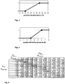
- Fig. 5 This will be in the Fig. 5 to 7 exemplifies a system with two radiators and the same nominal mass flow ⁇ nominal represent.
- the table according to Fig. 5 describes the total mass flow ratio as a function of the individual mass flow ratios of the radiators.
- Analog shows Fig. 6 the total return temperature as a function of the individual mass flow conditions of the radiator.
- Fig. 7 represents the values in Table 2 in a three-dimensional diagram.
- a total mass flow ratio of 0.3 may be, for. B., if both radiators are equally flowed through, so both radiators have a mass flow ratio of 0.3 based on the nominal mass flow ⁇ nominal for this radiator. The same occurs when one radiator has a mass flow ratio of 0.5 and the other has a mass flow ratio of 0.1.
- the total overflow temperature will be lower than in the second case (27.15 ° C to 30.24 ° C).
- the possible reduction in the second case must be based on the radiator, which has the larger mass flow ratio and thus the greater heat demand.
- a desired power reserve 80% from a mass flow ratio greater than 0.4, no further reduction may be made, or a flow temperature reduction should be withdrawn.
- heating systems have several heat meters, for example one per apartment or heating circuit, the heat demand of individual or all use units can be explicitly recorded, the method can be performed analogous to heating systems with a heat meter, for example. For each use unit. An additional gain in knowledge arises in terms of a uniform or uneven utilization of the individual radiator or their heat demand.
- the lowering times are periods in which the boiler temperature is reduced by the boiler control or the boiler is completely switched off, apart from a normally always active frost protection function. Especially in the The latter case, the heating circuit circulating pump is often switched off, which is recognizable by the mass flow. The end of the lowering or shutdown time is also recognizable when the mass flow increases again in a jump. If enough users show a recurring behavior, eg. B. at 22 o'clock turn off the radiator and at 6 o'clock turn up the radiator again, this can also be detected by the mass flow and / or the performance curve, even without system-controlled lowering.
- the typical mass flow and / or performance curves can be learned for different profile times, z. B. Morning / Afternoon / Evening / Night. In addition, a distinction can still be made between the working day and the weekend or public holiday, since here too a different user behavior typically results.
- the method can predicatively adjust to the expected change in the heat requirement before it can be detected at all via the change in the heat requirement or the heat demand tendency determined from the measured values. For example, in order to provide a higher heat output after a lowering phase of the heating system, the process starts at the beginning of the heating phase, i. after the end of a central night reduction of the flow temperature, predicatively with an increased flow temperature.
- the proposed method recognizes by evaluating the heat output tendencies, when the heat demand of the building as a whole decreases again and adjusts the flow temperature accordingly, taking into account the respective applicable Absenkgrenze.
- the mass flow signal of the heat meter can also be evaluated in order to obtain information about the use profile at the flat level.
- This information about the individual user profiles at the apartment level can be condensed to a profile of use on heating circuit or building level to reliably detect lowering and / or shutdown of the heating circuit or boiler, also starting from a specific user behavior.
- inactive heating surfaces As criterion for the determination of inactive heating surfaces on the basis of the data of the heat cost allocators two criteria can be applied. Thus, it is assumed that a heating surface is inactive when the difference between (rated) radiator side temperature and room air side temperature, ie the radiator overtemperature ⁇ FHKV is small. Furthermore, an inactive heating surface may be inferred if the estimated room air temperature ⁇ L is below a specified limit.
- G RL ⁇ 1 . f u ⁇ r ⁇ RL > 21 ° C 1 5 ⁇ RL - 16 . f u ⁇ r 16 ° C ⁇ ⁇ RL ⁇ 21 ° C and 0 . f u ⁇ r ⁇ RL > 16 ° C
- G ⁇ ⁇ 1 . f u ⁇ r ⁇ FHKV > 6 ° C 1 3 ⁇ FHKV - 1 .
- This sliding assessment between active and passive heating surfaces makes it possible to adequately consider heating surfaces with only low heat output when determining the heat demand, for example as a heat demand tendency and / or as a supply state.
- inventively proposed method is also suitable for use in the aforementioned method for adapting the heat output in heating systems based on the supply states in which the information of the water meter on mass flow, flow and return temperature are used to the accuracy of the method described therein improve.
- a flow temperature sensor is additionally attached to the end of the pipe, the heat difference between the pipe start and the end of the pipe can cause a optionally weighted or evenly distributed temperature distribution of the flow temperature can be applied to different floors of a larger heating system.
- An essential application for the present method in the supply state-based adaptive heat output control lies in a plausibility check of the determined Schumati- or building supply conditions.
- the building supply state With a high mass flow, the building supply state must recognize a shortage. At low mass flow, an oversupply must be detected. Furthermore, it can be checked on the basis of the determination of the heat demand tendency, whether the building supply state shows a corresponding change.
- the heat meter usually responds faster to the changed heat demand as determined from the valve positions of the radiator or their Schuvintemperaturen sizes, can be done with the faster trend calculation from the heat meter information faster adjustment of the flow temperature as in the quasi-stationary method for adaptive heat output control based on the supply state ,
Priority Applications (1)
| Application Number | Priority Date | Filing Date | Title |
|---|---|---|---|
| PL09174101T PL2182297T3 (pl) | 2008-10-30 | 2009-10-27 | Sposób i urządzenie do sterowanej zapotrzebowaniem na ciepło adaptacji temperatury zasilania instalacji grzewczej |
Applications Claiming Priority (1)
| Application Number | Priority Date | Filing Date | Title |
|---|---|---|---|
| DE102008054043A DE102008054043A1 (de) | 2008-10-30 | 2008-10-30 | Verfahren und Vorrichtung zur wärmebedarfsgeführten Adaption der Vorlauftemperatur einer Heizungsanlage |
Publications (3)
| Publication Number | Publication Date |
|---|---|
| EP2182297A2 EP2182297A2 (de) | 2010-05-05 |
| EP2182297A3 EP2182297A3 (de) | 2015-11-18 |
| EP2182297B1 true EP2182297B1 (de) | 2017-09-13 |
Family
ID=41625401
Family Applications (1)
| Application Number | Title | Priority Date | Filing Date |
|---|---|---|---|
| EP09174101.7A Active EP2182297B1 (de) | 2008-10-30 | 2009-10-27 | Verfahren und Vorrichtung zur wärmebedarfsgeführten Adaption der Vorlauftemperatur einer Heizungsanlage |
Country Status (4)
| Country | Link |
|---|---|
| EP (1) | EP2182297B1 (nl) |
| DE (1) | DE102008054043A1 (nl) |
| DK (1) | DK2182297T3 (nl) |
| PL (1) | PL2182297T3 (nl) |
Families Citing this family (8)
| Publication number | Priority date | Publication date | Assignee | Title |
|---|---|---|---|---|
| DE102011116179A1 (de) † | 2011-10-14 | 2013-04-18 | Metrona Wärmemesser Union Gmbh | Verfahren zur Steuerung einer Heizungsanlage und Heizungssteuerung |
| EP2863134B1 (de) * | 2013-10-15 | 2018-06-06 | Grundfos Holding A/S | Verfahren zum Anpassen einer Heizkurve |
| DE102016104667A1 (de) * | 2016-03-14 | 2017-09-14 | Techem Energy Services Gmbh | Verfahren und Steuereinrichtung zur Erhöhung des Nutzungsgrads eines Wärmeerzeugers in einer Heizungsanlage |
| DE102016104666A1 (de) * | 2016-03-14 | 2017-09-14 | Techem Energy Services Gmbh | Verfahren und Steuereinrichtung zur Erhöhung des Nutzungsgrads eines Wärmeerzeugers in einer Heizungsanlage |
| DE102018200653A1 (de) * | 2018-01-16 | 2019-07-18 | KSB SE & Co. KGaA | Verfahren zum Betrieb einer Heizungsanlage |
| EP3779286A1 (de) | 2019-08-12 | 2021-02-17 | Huu-Thoi Le | Verfahren zum betrieb einer heizanlage |
| DE102019005722A1 (de) * | 2019-08-12 | 2021-02-18 | Huu-Thoi Le | Verfahren zum Betrieb einer Heizungsanlage |
| DE102022001628A1 (de) | 2022-05-10 | 2023-11-16 | KSB SE & Co. KGaA | Verfahren zur Überwachung und/oder Steuerung einer Heizungsanlage |
Family Cites Families (9)
| Publication number | Priority date | Publication date | Assignee | Title |
|---|---|---|---|---|
| EP0260343B1 (de) | 1986-09-17 | 1993-01-20 | Viessmann Werke GmbH & Co. | Verfahren und Vorrichtung zur Temperaturregelung von Heizungs- und Kühlanlagen |
| DE3709085A1 (de) | 1987-03-19 | 1988-09-29 | Thomas Baehr | Verfahren zum steuern der vorlauftemperatur einer heizungsanlage |
| ATA237287A (de) | 1987-09-21 | 1993-02-15 | Vaillant Gmbh | Steuerung der temperatur des heizmediums einer umlaufheizung |
| DE50208516D1 (de) | 2001-12-19 | 2006-11-30 | Techem Energy Services Gmbh | Verfahren und vorrichtung zur adaption der waermeleistung in heizungsanlagen |
| DE10217272B4 (de) * | 2002-04-18 | 2006-02-23 | Helmut Dipl.-Ing. Lippok | Verfahren zur Wärmeleistungsregelung |
| JP2006105321A (ja) | 2004-10-07 | 2006-04-20 | Jtekt Corp | 軸受装置および軸受装置用支持軸 |
| DE102005012597A1 (de) | 2004-10-07 | 2006-04-27 | Techem Energy Services Gmbh & Co. Kg | Verfahren zur Bestimmung eines Heizflächen-Versorgungszustands und Versorgungszustandsregelung |
| DE102005045198C5 (de) | 2005-09-21 | 2009-06-25 | Techem Energy Services Gmbh | Verfahren und Vorrichtung zur Bestimmung von Wärmekenndaten eines Heizkörpers |
| DE102006013098C5 (de) * | 2006-03-20 | 2010-08-19 | Techem Energy Services Gmbh | Verfahren und Vorrichtung zur bedarfsgeführten Wärmebereitstellung in einer Heizungsanlage |
-
2008
- 2008-10-30 DE DE102008054043A patent/DE102008054043A1/de not_active Withdrawn
-
2009
- 2009-10-27 DK DK09174101.7T patent/DK2182297T3/da active
- 2009-10-27 PL PL09174101T patent/PL2182297T3/pl unknown
- 2009-10-27 EP EP09174101.7A patent/EP2182297B1/de active Active
Non-Patent Citations (1)
| Title |
|---|
| None * |
Also Published As
| Publication number | Publication date |
|---|---|
| EP2182297A2 (de) | 2010-05-05 |
| EP2182297A3 (de) | 2015-11-18 |
| PL2182297T3 (pl) | 2018-04-30 |
| DE102008054043A1 (de) | 2010-05-12 |
| DK2182297T3 (da) | 2018-01-02 |
Similar Documents
| Publication | Publication Date | Title |
|---|---|---|
| EP2182297B1 (de) | Verfahren und Vorrichtung zur wärmebedarfsgeführten Adaption der Vorlauftemperatur einer Heizungsanlage | |
| EP1645928B1 (de) | Verfahren zur Bestimmung eines Heizflächen-Versorgungszustands und Versorgungszustandsregler | |
| EP1936290B1 (de) | Verfahren und Vorrichtung zur Detektion des hydraulischen Zustands einer Heizungsanlage | |
| EP2863134B1 (de) | Verfahren zum Anpassen einer Heizkurve | |
| EP1456727B2 (de) | Verfahren und vorrichtung zur adaption der waermeleistung in heizungsanlagen | |
| EP2678563B1 (de) | Leistungsoptimiertes betreiben einer elektromotorisch angetriebenen pumpe durch mitkopplung | |
| DE2843929B2 (de) | Anordnung zur Steuerung der Raumtemperatur | |
| DE102017123560A1 (de) | Selbstregulierende Einstellvorrichtung für ein Durchflussregelventil, ein Temperierungssystem als auch eine Verteilervorrichtung mit derselben, sowie Verfahren hierzu | |
| DE102017203474A1 (de) | Verfahren zur Regelung einer drehzahlvariablen Umwälzpumpe sowie Umwälzpumpe | |
| DE102007030492A1 (de) | Gebäudemodellbasiertes prädiktives Regelverfahren zum Heizen eines begrenzten Systems | |
| DE102014102275B4 (de) | Verfahren zur Regelung einer Heizungs- und/oder Klimaanlage und Heizungs- und/oder Klimaanlage hierzu | |
| EP2009536B1 (de) | Verfahren und Vorrichtung zur Einstellung der Heizleistungsreserve | |
| DE102010053211A1 (de) | Verfahren zum Betreiben eines Heizungssystems | |
| DE102008040436A9 (de) | Verfahren zum Ermitteln einer Sollvorlauftemperatur für eine Regelung einer Warmwasserheizung eines Gebäudes | |
| EP0730213A2 (de) | Verfahren und Vorrichtung zur hydraulisch optimierten Regelung der Vorlauftemperatur | |
| WO2020165037A1 (de) | Verfahren zur regelung einer umwälzpumpe | |
| EP1235131B1 (de) | Raumtemperaturregelung | |
| DE3620929A1 (de) | Verfahren und einrichtung zur regelung mindestens einer heizung | |
| DE10144595A1 (de) | Zentralheizungsanlage | |
| EP3168540A1 (de) | Verfahren zum durchführen eines automatisierten hydraulischen abgleichs, ventil und heizungsanlage hierzu | |
| EP3739267B1 (de) | Verfahren und regeleinheit zum regeln eines heizkreises | |
| DE102009009197A1 (de) | Verfahren zur Regelung der Raumtemperatur | |
| DE3838005C2 (nl) | ||
| EP3062026A1 (de) | Temperaturregelungssystem | |
| EP2369245A1 (de) | Verfahren zum Anpassen eines Vorlauftemperatur-Sollwerts einer Heizkurve einer Heizungsanlage |
Legal Events
| Date | Code | Title | Description |
|---|---|---|---|
| PUAI | Public reference made under article 153(3) epc to a published international application that has entered the european phase |
Free format text: ORIGINAL CODE: 0009012 |
|
| AK | Designated contracting states |
Kind code of ref document: A2 Designated state(s): AT BE BG CH CY CZ DE DK EE ES FI FR GB GR HR HU IE IS IT LI LT LU LV MC MK MT NL NO PL PT RO SE SI SK SM TR |
|
| PUAL | Search report despatched |
Free format text: ORIGINAL CODE: 0009013 |
|
| AK | Designated contracting states |
Kind code of ref document: A3 Designated state(s): AT BE BG CH CY CZ DE DK EE ES FI FR GB GR HR HU IE IS IT LI LT LU LV MC MK MT NL NO PL PT RO SE SI SK SM TR |
|
| RIC1 | Information provided on ipc code assigned before grant |
Ipc: F24D 19/10 20060101AFI20151015BHEP |
|
| 17P | Request for examination filed |
Effective date: 20160204 |
|
| RBV | Designated contracting states (corrected) |
Designated state(s): AT BE BG CH CY CZ DE DK EE ES FI FR GB GR HR HU IE IS IT LI LT LU LV MC MK MT NL NO PL PT RO SE SI SK SM TR |
|
| GRAP | Despatch of communication of intention to grant a patent |
Free format text: ORIGINAL CODE: EPIDOSNIGR1 |
|
| STAA | Information on the status of an ep patent application or granted ep patent |
Free format text: STATUS: GRANT OF PATENT IS INTENDED |
|
| RIC1 | Information provided on ipc code assigned before grant |
Ipc: F24D 19/10 20060101AFI20170419BHEP Ipc: G05D 23/19 20060101ALI20170419BHEP |
|
| INTG | Intention to grant announced |
Effective date: 20170515 |
|
| GRAS | Grant fee paid |
Free format text: ORIGINAL CODE: EPIDOSNIGR3 |
|
| GRAA | (expected) grant |
Free format text: ORIGINAL CODE: 0009210 |
|
| STAA | Information on the status of an ep patent application or granted ep patent |
Free format text: STATUS: THE PATENT HAS BEEN GRANTED |
|
| AK | Designated contracting states |
Kind code of ref document: B1 Designated state(s): AT BE BG CH CY CZ DE DK EE ES FI FR GB GR HR HU IE IS IT LI LT LU LV MC MK MT NL NO PL PT RO SE SI SK SM TR |
|
| REG | Reference to a national code |
Ref country code: GB Ref legal event code: FG4D Free format text: NOT ENGLISH |
|
| REG | Reference to a national code |
Ref country code: CH Ref legal event code: EP |
|
| REG | Reference to a national code |
Ref country code: IE Ref legal event code: FG4D Free format text: LANGUAGE OF EP DOCUMENT: GERMAN |
|
| REG | Reference to a national code |
Ref country code: AT Ref legal event code: REF Ref document number: 928543 Country of ref document: AT Kind code of ref document: T Effective date: 20171015 |
|
| REG | Reference to a national code |
Ref country code: DE Ref legal event code: R096 Ref document number: 502009014359 Country of ref document: DE |
|
| REG | Reference to a national code |
Ref country code: CH Ref legal event code: NV Representative=s name: BOHEST AG, CH |
|
| REG | Reference to a national code |
Ref country code: DK Ref legal event code: T3 Effective date: 20171220 |
|
| REG | Reference to a national code |
Ref country code: NL Ref legal event code: MP Effective date: 20170913 |
|
| REG | Reference to a national code |
Ref country code: LT Ref legal event code: MG4D |
|
| PG25 | Lapsed in a contracting state [announced via postgrant information from national office to epo] |
Ref country code: NO Free format text: LAPSE BECAUSE OF FAILURE TO SUBMIT A TRANSLATION OF THE DESCRIPTION OR TO PAY THE FEE WITHIN THE PRESCRIBED TIME-LIMIT Effective date: 20171213 Ref country code: LT Free format text: LAPSE BECAUSE OF FAILURE TO SUBMIT A TRANSLATION OF THE DESCRIPTION OR TO PAY THE FEE WITHIN THE PRESCRIBED TIME-LIMIT Effective date: 20170913 Ref country code: HR Free format text: LAPSE BECAUSE OF FAILURE TO SUBMIT A TRANSLATION OF THE DESCRIPTION OR TO PAY THE FEE WITHIN THE PRESCRIBED TIME-LIMIT Effective date: 20170913 Ref country code: FI Free format text: LAPSE BECAUSE OF FAILURE TO SUBMIT A TRANSLATION OF THE DESCRIPTION OR TO PAY THE FEE WITHIN THE PRESCRIBED TIME-LIMIT Effective date: 20170913 Ref country code: SE Free format text: LAPSE BECAUSE OF FAILURE TO SUBMIT A TRANSLATION OF THE DESCRIPTION OR TO PAY THE FEE WITHIN THE PRESCRIBED TIME-LIMIT Effective date: 20170913 |
|
| PG25 | Lapsed in a contracting state [announced via postgrant information from national office to epo] |
Ref country code: GR Free format text: LAPSE BECAUSE OF FAILURE TO SUBMIT A TRANSLATION OF THE DESCRIPTION OR TO PAY THE FEE WITHIN THE PRESCRIBED TIME-LIMIT Effective date: 20171214 Ref country code: ES Free format text: LAPSE BECAUSE OF FAILURE TO SUBMIT A TRANSLATION OF THE DESCRIPTION OR TO PAY THE FEE WITHIN THE PRESCRIBED TIME-LIMIT Effective date: 20170913 Ref country code: LV Free format text: LAPSE BECAUSE OF FAILURE TO SUBMIT A TRANSLATION OF THE DESCRIPTION OR TO PAY THE FEE WITHIN THE PRESCRIBED TIME-LIMIT Effective date: 20170913 Ref country code: BG Free format text: LAPSE BECAUSE OF FAILURE TO SUBMIT A TRANSLATION OF THE DESCRIPTION OR TO PAY THE FEE WITHIN THE PRESCRIBED TIME-LIMIT Effective date: 20171213 |
|
| PG25 | Lapsed in a contracting state [announced via postgrant information from national office to epo] |
Ref country code: NL Free format text: LAPSE BECAUSE OF FAILURE TO SUBMIT A TRANSLATION OF THE DESCRIPTION OR TO PAY THE FEE WITHIN THE PRESCRIBED TIME-LIMIT Effective date: 20170913 |
|
| PG25 | Lapsed in a contracting state [announced via postgrant information from national office to epo] |
Ref country code: RO Free format text: LAPSE BECAUSE OF FAILURE TO SUBMIT A TRANSLATION OF THE DESCRIPTION OR TO PAY THE FEE WITHIN THE PRESCRIBED TIME-LIMIT Effective date: 20170913 Ref country code: CZ Free format text: LAPSE BECAUSE OF FAILURE TO SUBMIT A TRANSLATION OF THE DESCRIPTION OR TO PAY THE FEE WITHIN THE PRESCRIBED TIME-LIMIT Effective date: 20170913 |
|
| PG25 | Lapsed in a contracting state [announced via postgrant information from national office to epo] |
Ref country code: IS Free format text: LAPSE BECAUSE OF FAILURE TO SUBMIT A TRANSLATION OF THE DESCRIPTION OR TO PAY THE FEE WITHIN THE PRESCRIBED TIME-LIMIT Effective date: 20180113 Ref country code: IT Free format text: LAPSE BECAUSE OF FAILURE TO SUBMIT A TRANSLATION OF THE DESCRIPTION OR TO PAY THE FEE WITHIN THE PRESCRIBED TIME-LIMIT Effective date: 20170913 Ref country code: EE Free format text: LAPSE BECAUSE OF FAILURE TO SUBMIT A TRANSLATION OF THE DESCRIPTION OR TO PAY THE FEE WITHIN THE PRESCRIBED TIME-LIMIT Effective date: 20170913 Ref country code: SK Free format text: LAPSE BECAUSE OF FAILURE TO SUBMIT A TRANSLATION OF THE DESCRIPTION OR TO PAY THE FEE WITHIN THE PRESCRIBED TIME-LIMIT Effective date: 20170913 Ref country code: SM Free format text: LAPSE BECAUSE OF FAILURE TO SUBMIT A TRANSLATION OF THE DESCRIPTION OR TO PAY THE FEE WITHIN THE PRESCRIBED TIME-LIMIT Effective date: 20170913 |
|
| REG | Reference to a national code |
Ref country code: DE Ref legal event code: R097 Ref document number: 502009014359 Country of ref document: DE |
|
| PG25 | Lapsed in a contracting state [announced via postgrant information from national office to epo] |
Ref country code: MC Free format text: LAPSE BECAUSE OF FAILURE TO SUBMIT A TRANSLATION OF THE DESCRIPTION OR TO PAY THE FEE WITHIN THE PRESCRIBED TIME-LIMIT Effective date: 20170913 |
|
| PLBE | No opposition filed within time limit |
Free format text: ORIGINAL CODE: 0009261 |
|
| STAA | Information on the status of an ep patent application or granted ep patent |
Free format text: STATUS: NO OPPOSITION FILED WITHIN TIME LIMIT |
|
| REG | Reference to a national code |
Ref country code: IE Ref legal event code: MM4A |
|
| REG | Reference to a national code |
Ref country code: FR Ref legal event code: ST Effective date: 20180629 |
|
| PG25 | Lapsed in a contracting state [announced via postgrant information from national office to epo] |
Ref country code: LU Free format text: LAPSE BECAUSE OF NON-PAYMENT OF DUE FEES Effective date: 20171027 |
|
| 26N | No opposition filed |
Effective date: 20180614 |
|
| REG | Reference to a national code |
Ref country code: BE Ref legal event code: MM Effective date: 20171031 |
|
| GBPC | Gb: european patent ceased through non-payment of renewal fee |
Effective date: 20171213 |
|
| PG25 | Lapsed in a contracting state [announced via postgrant information from national office to epo] |
Ref country code: BE Free format text: LAPSE BECAUSE OF NON-PAYMENT OF DUE FEES Effective date: 20171031 Ref country code: FR Free format text: LAPSE BECAUSE OF NON-PAYMENT OF DUE FEES Effective date: 20171113 |
|
| PG25 | Lapsed in a contracting state [announced via postgrant information from national office to epo] |
Ref country code: MT Free format text: LAPSE BECAUSE OF FAILURE TO SUBMIT A TRANSLATION OF THE DESCRIPTION OR TO PAY THE FEE WITHIN THE PRESCRIBED TIME-LIMIT Effective date: 20170913 |
|
| PG25 | Lapsed in a contracting state [announced via postgrant information from national office to epo] |
Ref country code: IE Free format text: LAPSE BECAUSE OF NON-PAYMENT OF DUE FEES Effective date: 20171027 |
|
| PG25 | Lapsed in a contracting state [announced via postgrant information from national office to epo] |
Ref country code: GB Free format text: LAPSE BECAUSE OF NON-PAYMENT OF DUE FEES Effective date: 20171213 Ref country code: SI Free format text: LAPSE BECAUSE OF FAILURE TO SUBMIT A TRANSLATION OF THE DESCRIPTION OR TO PAY THE FEE WITHIN THE PRESCRIBED TIME-LIMIT Effective date: 20170913 |
|
| PGFP | Annual fee paid to national office [announced via postgrant information from national office to epo] |
Ref country code: PL Payment date: 20181008 Year of fee payment: 10 Ref country code: DK Payment date: 20181025 Year of fee payment: 10 Ref country code: AT Payment date: 20181019 Year of fee payment: 10 |
|
| PGFP | Annual fee paid to national office [announced via postgrant information from national office to epo] |
Ref country code: CH Payment date: 20181025 Year of fee payment: 10 |
|
| PG25 | Lapsed in a contracting state [announced via postgrant information from national office to epo] |
Ref country code: HU Free format text: LAPSE BECAUSE OF FAILURE TO SUBMIT A TRANSLATION OF THE DESCRIPTION OR TO PAY THE FEE WITHIN THE PRESCRIBED TIME-LIMIT; INVALID AB INITIO Effective date: 20091027 |
|
| PG25 | Lapsed in a contracting state [announced via postgrant information from national office to epo] |
Ref country code: CY Free format text: LAPSE BECAUSE OF NON-PAYMENT OF DUE FEES Effective date: 20170913 |
|
| PG25 | Lapsed in a contracting state [announced via postgrant information from national office to epo] |
Ref country code: MK Free format text: LAPSE BECAUSE OF FAILURE TO SUBMIT A TRANSLATION OF THE DESCRIPTION OR TO PAY THE FEE WITHIN THE PRESCRIBED TIME-LIMIT Effective date: 20170913 |
|
| PG25 | Lapsed in a contracting state [announced via postgrant information from national office to epo] |
Ref country code: TR Free format text: LAPSE BECAUSE OF FAILURE TO SUBMIT A TRANSLATION OF THE DESCRIPTION OR TO PAY THE FEE WITHIN THE PRESCRIBED TIME-LIMIT Effective date: 20170913 |
|
| REG | Reference to a national code |
Ref country code: DK Ref legal event code: EBP Effective date: 20191031 |
|
| PG25 | Lapsed in a contracting state [announced via postgrant information from national office to epo] |
Ref country code: PT Free format text: LAPSE BECAUSE OF FAILURE TO SUBMIT A TRANSLATION OF THE DESCRIPTION OR TO PAY THE FEE WITHIN THE PRESCRIBED TIME-LIMIT Effective date: 20170913 |
|
| REG | Reference to a national code |
Ref country code: CH Ref legal event code: PL |
|
| PG25 | Lapsed in a contracting state [announced via postgrant information from national office to epo] |
Ref country code: LI Free format text: LAPSE BECAUSE OF NON-PAYMENT OF DUE FEES Effective date: 20191031 Ref country code: CH Free format text: LAPSE BECAUSE OF NON-PAYMENT OF DUE FEES Effective date: 20191031 |
|
| REG | Reference to a national code |
Ref country code: AT Ref legal event code: MM01 Ref document number: 928543 Country of ref document: AT Kind code of ref document: T Effective date: 20191027 |
|
| PG25 | Lapsed in a contracting state [announced via postgrant information from national office to epo] |
Ref country code: DK Free format text: LAPSE BECAUSE OF NON-PAYMENT OF DUE FEES Effective date: 20191031 |
|
| PG25 | Lapsed in a contracting state [announced via postgrant information from national office to epo] |
Ref country code: AT Free format text: LAPSE BECAUSE OF NON-PAYMENT OF DUE FEES Effective date: 20191027 |
|
| PG25 | Lapsed in a contracting state [announced via postgrant information from national office to epo] |
Ref country code: PL Free format text: LAPSE BECAUSE OF NON-PAYMENT OF DUE FEES Effective date: 20191027 |
|
| P01 | Opt-out of the competence of the unified patent court (upc) registered |
Effective date: 20230527 |
|
| PGFP | Annual fee paid to national office [announced via postgrant information from national office to epo] |
Ref country code: DE Payment date: 20231031 Year of fee payment: 15 |