EP2182205A1 - Agencement d'éolienne et procédé d'alignement d'une éolienne avec la direction du vent - Google Patents
Agencement d'éolienne et procédé d'alignement d'une éolienne avec la direction du vent Download PDFInfo
- Publication number
- EP2182205A1 EP2182205A1 EP08018796A EP08018796A EP2182205A1 EP 2182205 A1 EP2182205 A1 EP 2182205A1 EP 08018796 A EP08018796 A EP 08018796A EP 08018796 A EP08018796 A EP 08018796A EP 2182205 A1 EP2182205 A1 EP 2182205A1
- Authority
- EP
- European Patent Office
- Prior art keywords
- pressure
- nacelle
- wind turbine
- wind
- difference
- Prior art date
- Legal status (The legal status is an assumption and is not a legal conclusion. Google has not performed a legal analysis and makes no representation as to the accuracy of the status listed.)
- Granted
Links
- 238000000034 method Methods 0.000 title claims abstract description 28
- 230000003044 adaptive effect Effects 0.000 claims description 2
- 230000001537 neural effect Effects 0.000 claims description 2
- 238000012937 correction Methods 0.000 description 7
- 238000009530 blood pressure measurement Methods 0.000 description 4
- 230000004044 response Effects 0.000 description 4
- 238000001514 detection method Methods 0.000 description 3
- 238000010586 diagram Methods 0.000 description 3
- 238000005259 measurement Methods 0.000 description 3
- 230000004048 modification Effects 0.000 description 3
- 238000012986 modification Methods 0.000 description 3
- 230000008569 process Effects 0.000 description 3
- 230000010354 integration Effects 0.000 description 2
- 239000012528 membrane Substances 0.000 description 2
- 239000000523 sample Substances 0.000 description 2
- 230000003068 static effect Effects 0.000 description 2
- 238000006243 chemical reaction Methods 0.000 description 1
- 230000003247 decreasing effect Effects 0.000 description 1
- 238000011161 development Methods 0.000 description 1
- 230000018109 developmental process Effects 0.000 description 1
- 238000004519 manufacturing process Methods 0.000 description 1
- 230000009467 reduction Effects 0.000 description 1
Images


Classifications
-
- F—MECHANICAL ENGINEERING; LIGHTING; HEATING; WEAPONS; BLASTING
- F03—MACHINES OR ENGINES FOR LIQUIDS; WIND, SPRING, OR WEIGHT MOTORS; PRODUCING MECHANICAL POWER OR A REACTIVE PROPULSIVE THRUST, NOT OTHERWISE PROVIDED FOR
- F03D—WIND MOTORS
- F03D7/00—Controlling wind motors
- F03D7/02—Controlling wind motors the wind motors having rotation axis substantially parallel to the air flow entering the rotor
- F03D7/04—Automatic control; Regulation
- F03D7/042—Automatic control; Regulation by means of an electrical or electronic controller
-
- F—MECHANICAL ENGINEERING; LIGHTING; HEATING; WEAPONS; BLASTING
- F03—MACHINES OR ENGINES FOR LIQUIDS; WIND, SPRING, OR WEIGHT MOTORS; PRODUCING MECHANICAL POWER OR A REACTIVE PROPULSIVE THRUST, NOT OTHERWISE PROVIDED FOR
- F03D—WIND MOTORS
- F03D7/00—Controlling wind motors
- F03D7/02—Controlling wind motors the wind motors having rotation axis substantially parallel to the air flow entering the rotor
- F03D7/0204—Controlling wind motors the wind motors having rotation axis substantially parallel to the air flow entering the rotor for orientation in relation to wind direction
-
- F—MECHANICAL ENGINEERING; LIGHTING; HEATING; WEAPONS; BLASTING
- F05—INDEXING SCHEMES RELATING TO ENGINES OR PUMPS IN VARIOUS SUBCLASSES OF CLASSES F01-F04
- F05B—INDEXING SCHEME RELATING TO WIND, SPRING, WEIGHT, INERTIA OR LIKE MOTORS, TO MACHINES OR ENGINES FOR LIQUIDS COVERED BY SUBCLASSES F03B, F03D AND F03G
- F05B2260/00—Function
- F05B2260/80—Diagnostics
-
- F—MECHANICAL ENGINEERING; LIGHTING; HEATING; WEAPONS; BLASTING
- F05—INDEXING SCHEMES RELATING TO ENGINES OR PUMPS IN VARIOUS SUBCLASSES OF CLASSES F01-F04
- F05B—INDEXING SCHEME RELATING TO WIND, SPRING, WEIGHT, INERTIA OR LIKE MOTORS, TO MACHINES OR ENGINES FOR LIQUIDS COVERED BY SUBCLASSES F03B, F03D AND F03G
- F05B2270/00—Control
- F05B2270/30—Control parameters, e.g. input parameters
- F05B2270/301—Pressure
- F05B2270/3015—Pressure differential
-
- F—MECHANICAL ENGINEERING; LIGHTING; HEATING; WEAPONS; BLASTING
- F05—INDEXING SCHEMES RELATING TO ENGINES OR PUMPS IN VARIOUS SUBCLASSES OF CLASSES F01-F04
- F05B—INDEXING SCHEME RELATING TO WIND, SPRING, WEIGHT, INERTIA OR LIKE MOTORS, TO MACHINES OR ENGINES FOR LIQUIDS COVERED BY SUBCLASSES F03B, F03D AND F03G
- F05B2270/00—Control
- F05B2270/30—Control parameters, e.g. input parameters
- F05B2270/324—Air pressure
-
- F—MECHANICAL ENGINEERING; LIGHTING; HEATING; WEAPONS; BLASTING
- F05—INDEXING SCHEMES RELATING TO ENGINES OR PUMPS IN VARIOUS SUBCLASSES OF CLASSES F01-F04
- F05B—INDEXING SCHEME RELATING TO WIND, SPRING, WEIGHT, INERTIA OR LIKE MOTORS, TO MACHINES OR ENGINES FOR LIQUIDS COVERED BY SUBCLASSES F03B, F03D AND F03G
- F05B2270/00—Control
- F05B2270/80—Devices generating input signals, e.g. transducers, sensors, cameras or strain gauges
- F05B2270/802—Calibration thereof
-
- Y—GENERAL TAGGING OF NEW TECHNOLOGICAL DEVELOPMENTS; GENERAL TAGGING OF CROSS-SECTIONAL TECHNOLOGIES SPANNING OVER SEVERAL SECTIONS OF THE IPC; TECHNICAL SUBJECTS COVERED BY FORMER USPC CROSS-REFERENCE ART COLLECTIONS [XRACs] AND DIGESTS
- Y02—TECHNOLOGIES OR APPLICATIONS FOR MITIGATION OR ADAPTATION AGAINST CLIMATE CHANGE
- Y02B—CLIMATE CHANGE MITIGATION TECHNOLOGIES RELATED TO BUILDINGS, e.g. HOUSING, HOUSE APPLIANCES OR RELATED END-USER APPLICATIONS
- Y02B10/00—Integration of renewable energy sources in buildings
- Y02B10/30—Wind power
-
- Y—GENERAL TAGGING OF NEW TECHNOLOGICAL DEVELOPMENTS; GENERAL TAGGING OF CROSS-SECTIONAL TECHNOLOGIES SPANNING OVER SEVERAL SECTIONS OF THE IPC; TECHNICAL SUBJECTS COVERED BY FORMER USPC CROSS-REFERENCE ART COLLECTIONS [XRACs] AND DIGESTS
- Y02—TECHNOLOGIES OR APPLICATIONS FOR MITIGATION OR ADAPTATION AGAINST CLIMATE CHANGE
- Y02E—REDUCTION OF GREENHOUSE GAS [GHG] EMISSIONS, RELATED TO ENERGY GENERATION, TRANSMISSION OR DISTRIBUTION
- Y02E10/00—Energy generation through renewable energy sources
- Y02E10/70—Wind energy
- Y02E10/72—Wind turbines with rotation axis in wind direction
Definitions
- the present invention relates to a wind turbine arrangement and to method for aligning a wind turbine with the wind direction.
- the alignment of, for example, horizontal axis wind turbines into a particular wind direction is crucial in order to avoid high structural loads and in order to produce optimal power.
- the wind direction is typically measured by use of a wind vane or by use of a sonic wind sensor.
- a device for determining the wind energy in order to control wind generators, especially in order to align the position of the plane of rotation of the rotor in relation to the air flow is disclosed.
- the wind energy at the rotor plane is controlled with the aid of a pressure difference measured by probes, wherein the pressure probes are arranged at the surface of the rotor blades. If the measuring system registers unequal initial wind angles in the 90° and 270° rotor position, then the blades have to be adjusted in the 0° and 180° position so that the rotor plane pivots about the tower axis so as to balance the difference in the initial wind angles at 90° and 270° again.
- the first objective is solved by a method as claimed in claim 1, the second objective by a wind turbine arrangement as claimed in claim 10.
- the depending claims contain further developments of the invention.
- the inventive method for aligning a wind turbine with the wind direction comprises the steps of measuring at least a first pressure at a first side of a wind turbine nacelle and determining the pressure difference between the measured first pressure and a second pressure. The nacelle is then rotated in dependence or in response to the determined pressure difference.
- the second pressure may be a reference pressure which is calibrated to correspond to correct alignment of the wind turbine with the wind, or a pressure measured at a second side of the wind turbines nacelle which is located opposite to the first side.
- the difference between the at least one pressure value measured at one side of the nacelle and the reference pressure, or the difference between pressure values measured at both sides of the nacelle is used by the wind turbine control system to correct yaw misalignment of the wind turbine rotor.
- the measured first pressure and/or the measured second pressure may be integrated over time periods before determining the pressure difference.
- the inventive method can be performed irrespective whether dynamic pressures or static pressures or combination thereof are measured as the first pressure and/or the second pressure. Furthermore, more than one pressure may be measured at the first side of the nacelle and/or more than one pressure may be measured at the second side of the nacelle. The pressures measured at the first side of the nacelle are then combined and/or the pressures measured at the second side of the nacelle are then combined before determining the pressure difference. Alternatively, more than one pressure difference is determined and the determined pressure differences are combined before rotating the nacelle in dependence or in response to the combined pressure difference. The pressures measured at the same side of the nacelle may result from the same kind of pressure measurement or from different kinds of pressure measurements. By combining a number of pressure measurements at each side of the nacelle the inventive method can be made even more robust. Note that in the following the terms "pressure difference” or "determined pressure difference” shall also include the combined pressure difference without explicitly mentioning it.
- a maximum limit and/or a minimum limit for the pressure difference may be defined.
- the rotation of the nacelle may then be started in case the pressure difference reaches or exceeds the defined maximum limit and/or the rotation of the nacelle may be stopped in case the pressure difference reaches or falls under the defined minimum limit.
- the maximum limit and the minimum limit may also be identical.
- the method may comprise a step of calibrating the pressure difference and/or the defined maximum limit and/or the defined minimum limit according to wind speed and/or rotational speed of the wind turbine rotor.
- An inventive wind turbine arrangement comprises a nacelle with a first side and a second side being located opposite to the first side. It further comprises a yaw alignment controller and a yaw drive connected to the yaw alignment controller.
- the yaw alignment controller is designed to determine a misalignment of the wind turbine with the wind direction, i.e. a yaw error, and to produce a control signal representing a turning of the wind turbine which leads to realignment of the wind turbine with the wind direction.
- a yaw drive is connected to the yaw alignment controller for receiving the control signal.
- the yaw drive is designed to align the wind turbine with the wind direction on the basis of the control signal.
- At least one first pressure gauge is located at the first side of the nacelle, the pressure gauge producing a first pressure signal.
- the yaw alignment controller is connected to the at least one first pressure gauge for receiving the first pressure signal. It is designed to determine the pressure difference between the first pressure signal and a second pressure signal, and to output the control signal representing a turning of the nacelle in dependence or in response to the determined pressure difference.
- the yaw alignment controller may be, or comprise, a PID-controller or a neuronal network or a fuzzy logic controller or an adaptive controller.
- the inventive wind turbine arrangement is adapted to perform the inventive method and, hence, achieves the advantages already described with respect to the inventive method.
- the turning may, in particular, be performed by using a defined maximum limit for starting the rotation and/or a defined minimum limit for stopping the rotation.
- At least one second pressure gauge may be located at the second side of the nacelle, the second pressure gauge producing the second pressure signal.
- the yaw alignment controller can be connected to the at least one second pressure gauge for receiving the second pressure signal.
- the wind turbine arrangement may comprise a reference pressure repository containing a reference pressure which is calibrated to correspond to correct alignment of the wind turbine with the wind.
- the yaw alignment controller can be connected to the reference pressure repository for receiving the reference pressure as the second pressure signal.
- the location of the pressure gauges may be anywhere on the nacelle sides.
- the yaw alignment controller may be located at a central control instance and be responsible for a number of wind turbines.
- the signals of the pressure gauges of the individual wind turbines could then, for example, be transmitted to the yaw alignment controller according to a time scheme.
- an individual wind turbine may be equipped with a yaw alignment controller of its own.
- the yaw alignment controller may be a part of or incorporated into the wind turbine controller
- More than one pressure gauge may be located at the first side of the nacelle and/or more than one pressure gauge may be located at the second side of the nacelle, each pressure gauge producing a pressure signal.
- the yaw alignment controller is then connected to all pressure gauges for receiving the respective pressure signals and designed to combine the pressure signals from the pressure gauges located at the first side of the nacelle to a first combined pressure signal and/or to combine the pressure signals from the pressure gauges located at the second side of the nacelle to a second combined pressure signal before determining the pressure difference.
- the yaw alignment controller can be designated to determine more than one pressure difference and to combine the determined pressure differences before it outputs the control signal representing a turning of the nacelle in dependence or in response to the combined pressure difference. Measuring the pressures at more than one location at a nacelles side allows for increasing robustness in determining of the yaw misalignment further.
- the yaw alignment controller may comprise or may be connected to, a calibration unit which is designed to calibrate the difference between the first pressure signal and the second pressure signal and/or a defined maximum limit and/or a defined minimum limit according to wind speed and/or rotational speed of the rotor.
- the calibration unit may provide a table which defines correction values to the be made to the determined pressure difference for given values of rotor rotational speeds and/or given values of wind speeds. Instead, the correction could be done at the side of a defined pressure difference limit.
- pressure gauges for example Pitot tubes, strain gauges, Piezoelectric pressure sensors, membrane pressure sensors, etc., or combinations thereof.
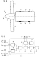
- Figure 1 shows a wind turbine of an inventive wind turbine arrangement as seen from above.
- the wind turbine comprises a nacelle 1 located on top of a wind turbine tower.
- the tower itself is not visible in the figure since it is located below the nacelle 1.
- the nacelle 1 houses an electrical generator the moving part of which is connected to the wind turbine rotor 5 by a shaft 3.
- the rotor 5 comprises a rotor hub 7 from which, in the present embodiment, three rotor blades 9 extend radially outwards (only two of three blades are visible in the figure). Note, that the number of blades may be different from three, for example two. However, three-bladed rotors are the most common for the time being.
- the axis A of the shaft 3 i.e. the rotor axis
- a yaw drive is located between the tower top and the nacelle 1 (the yaw drive is not visible in figure 1 ).
- a yaw alignment controller is present which produces control signals representing a turning of the wind turbines rotor axis A which leads the rotor axis A to align with the wind direction.
- the yaw alignment controller and the yaw drive are schematically shown in figure 2 .
- the yaw alignment controller 11 is connected to a first Pitot tube 13 and a second Pitot tube 15 which are located at a first side 17 and a second side 19 of the nacelle, respectively.
- the second side 19 is located opposite to the first side 17.
- the first Pitot tube 13 measures the dynamic pressure of the wind at a first side 17 of the nacelle 1 while the second Pitot tube 15 measures the dynamic pressure of the wind at the opposite side 19 of the nacelle 1.
- the first and second pressure gauges produce first and second pressure signals, respectively.
- Pitot tubes are only one possible kind of pressure gauges which may be used with the present invention. Other pressure gauges, also such pressure gauges measuring static pressure instead of dynamic pressure, may be used, as well. Examples of other pressure gauges are strain gauges, Piezoelectric pressure sensors, membrane pressure sensors, etc.
- the first and second pressure signals produced by the first and second Pitot tubes 13, 15 are received by a subtraction unit 21 which subtracts the first pressure signal from the second pressure signal, or vice versa and outputs a difference signal representative of a difference between the first and the second pressure signal, i.e. representing the pressure difference between both sides 17, 19 of the nacelle 1.
- the subtraction unit 21 can, for example, be realized as a differential amplifier. Note that, like all other units of the yaw alignment controller 11, the subtraction unit 21 can, in principle, be realized in form of hardware as well as in form of software running on a suitable hardware environment.
- the difference signal is received by a comparator 23 which is connected to the subtraction unit 21 for receiving the difference signal and which compares the difference signals with a defined maximum limit. In case the defined maximum limit is exceeded a yaw misalignment has occurred that is out of acceptance limits. In this case the comparator determines the extends by which the given maximum limit is exceeded and produces a comparation signal representing the extend by which the defined maximum limit is exceeded.
- the comparation signal is received by a control unit 25 which is connected to the comparator 23 and which produces, on the basis of the comparation signal, a control signal representing a turning of the rotor axis A in horizontal direction in order to realign the axis with the wind direction.
- This control signal is then output to the wind turbine's yaw drive 27.
- the comparator 23 receives the defined maximum limit from a calibration unit 29 which is connected to the subtraction unit 21, to a rotor speed sensor 31 and to a wind speed sensor 33.
- the calibration unit 29 is connected to a memory 35.
- the calibration unit 29 serves for calibrating the defined pressure difference maximum limit according to wind speed and rotor speed in order to account for minor non-symmetries in the air flow around the nacelle 1 which may be introduced by the rotation of the rotor 5.
- Such calibration can, for example, be repeatedly done in given time intervals or as soon as certain changes in rotor speed and/or wind speed are detected.
- the calibration unit 29 produces corrective values for the defined maximum limit used in the comparator.
- This correction values are stored in the memory 35, e.g. in form of a table assigning correction values to measurement values of wind speed and/or rotor speed.
- the calibration unit 29 retrieves, depending on the measured wind speed and/or rotor speed, a correction value corresponding to the measured wind speed and/or rotor speed and corrects the defined maximum limit with the retrieved correction value before the defined maximum limit is output to the comparator 23.
- the difference signal is received from the subtraction unit 21 only for performing the calibration process.
- the comparator 23 would not be directly connected to the subtraction unit 21, as it is in embodiment shown in figure 2 , but only via the calibration unit 29.
- the calibration unit 29 would then correct the difference signal received from the subtraction unit 21 with the correction value retrieved from the memory 35.
- the corrected difference signal would be output to the comparator 23.
- the comparator 23 would, in this case, contain or receive an unmodified defined maximum limit which it would compare with the corrected difference signal.
- the yaw alignment controller 11 produces and outputs a control signal which leads to a yawing motion of the nacelle until the defined maximum limit, whether modified or unmodified, is not exceeded anymore. Then, the yawing motion stops since the rotor axis A is realigned with the wind direction within acceptable limits.
- the defined maximum limit is used for starting and stopping the rotation in the present embodiment, a different limit than the maximum limit could be used for stopping the rotation. Such a limit called a minimum limit would, in particular, be smaller than the maximum limit.
- FIG. 3 A modification of the controller shown in figure 2 is depicted in figure 3 . Elements of the modified controller 11' which do not differ from the controller 11 of figure 2 are denominated with the same reference numerals and will not be described again to avoid redundancies.
- the modified controller 11' shown in figure 3 differs from the controller 11 shown in figure 2 in that the Pitot tubes 13, 15 are not directly connected to the subtraction unit 21. Instead, the first pressure senor 13 and the second pressure sensor 15 are connected to a fist integrator 37 and a second integrator 39, respectively. These integrators integrate the received pressure signals over a given time period for producing a first integrated pressure signal and a second integrated pressure signal, respectively. The fist integrated pressure signal and the second integrated pressure signal are then further processed in the same way as the fist pressure signal and the second pressure signal in the controller 11 shown in figure 2 . By integrating the pressure signals a more robust determination of the yaw misalignment of the rotor axis A is possible.
- a wind turbine of a second embodiment of the inventive wind turbine arrangement is shown in figure 4 .
- the second embodiment differs from the first embodiment in that additional pressure gauges 41, 43 are present on each side 17, 19 of the nacelle 1.
- These additional pressure gauges 41, 43 may be pressure gauges of the same kind as the first pressure gauge 13 and the second pressure gauge 15. However, different kinds of pressure gauges may be used as well.
- the second embodiment does not differ from the elements of the first embodiment shown in figure 1 . Therefore, elements which have already been described with respect to the first embodiment and do not differ from elements in the second embodiment are denominated with the same reference numerals and will not be explained again.
- the yaw alignment controller 111 of the second embodiment is schematically shown in figure 5 .
- the controller differs from the controller shown in figure 2 in that combination units 45, 47 are present.
- the yaw alignment controller 111 does not differ from the yaw alignment controller 11 of figure 2 .
- Elements which are identical with those of the yaw alignment controller of figure 2 are denominated with the same reference numerals as in figure 2 and will not be explained again.
- the first combination unit 45 is connected to the pressure gauges 13, 41 1 ...41 n at the first side 17 of the nacelle.
- the second combination unit 47 is connected to the pressure gauges 15, 43 1 ...43 n at the second side 19 of the nacelle.
- the combination units 45, 47 are used for combining the pressure signals of all pressure gauges at one side of the nacelle 1 and to output a first combined pressure signal and a second combined pressure signal, respectively, to the subtraction unit 21.
- Combining the pressure signals measured at one side 17, 19 of the nacelle 1 can be done in various ways which depend on the kinds of pressure gauges used for producing the pressure signals. In case all pressure gauges are of the same kind a mean value or a weighted mean value can be used as combined pressure signal. The weights may, e.g., depend on the location of the respective pressure gauges on the side of the nacelle 1.
- the first and second combined pressure signals resulting from combining the pressure signals of the pressure gauges are then further processed in the same way as the first and the second pressure signals in the yaw alignment controller 11 shown in figure 2 .
- the yaw alignment controller 111 may further comprise integration units as they have been described with respect to figure 3 .
- Such integration units may be located before or after the combination unit 45, 47. If they are located after the combination units 45, 47 only one integrator would be needed for each side of the nacelle 1. In the other case, an integrator would be needed for each single pressure signal which is to be integrated. Note that it would generally be possible to locate the integrators before the combination units 45, 47 but not integrating each single pressure signal.
- different kinds of pressure gauges are used at a side of the nacelle 1 it may be advantageous to integrate the signals produced by some kinds of pressure gauges while not integrating the signals of other kinds of pressure gauges, i.g. because some kinds of the used pressure gauges already produce integrated signals.
- individual difference signals can be produced for pressure signals delivered by corresponding pressure gauges at the first and second side of the nacelle 1.
- the individual difference signals are then combined to form a combined difference signal that will be compared to the defined limit.
- a number of subtraction units would be present which are located between the pressure gauges and a single combination unit.
- the combination unit would be further connected to the comparator 23, the calibration unit 29, and the control unit 25.
- a wind turbine of a third embodiment of the inventive wind turbine arrangement is shown in figure 6 .
- the third embodiment differs from the first embodiment in that only the pressure gauge at the first side 17 of the nacelle 1 is present.
- the second embodiment does not differ from the elements of the first embodiment shown in figure 1 . Therefore, elements which have already been described with respect to the first embodiment and do not differ from elements in the second embodiment are denominated with the same reference numerals and will not be explained again.
- the yaw alignment controller 211 of the third embodiment is schematically shown in figure 7 .
- the controller differs from the controller shown in figure 2 in that the subtraction unit 21 is connected to a reference pressure repository 22 containing a reference pressure which is calibrated to correspond to correct alignment of the wind turbine with the wind.
- the reference pressure is then used instead of the pressure measured by the second pressure gauge of the first embodiment for determining the difference signal.
- the yaw alignment controller 211 of the third embodiment does not differ from yaw alignment controller 11 of the first embodiment.
- the yaw alignment controller 211 of the third embodiment may comprise an integrator as it has been described with respect to figure 3 for integrating the pressure signal from the pressure gauge 13 over a given time period.
- the calibrated reference pressure may depend on the kind of wind turbine and on the location of the wind turbine. Therefore, a calibration procedure is preferably carried out for each wind turbine after erection. However, if wind turbines of the same kind are used at locations which are expected to show identical wind flow conditions a common reference pressure may be established for such wind turbines, by a single calibration procedure. The calibration procedure for a single wind turbine or a group of similar wind turbines may be repeated from time to time or if wind flow conditions at a wind turbine location have changed, for instance due to newly constructed buildings or new wind turbines in a wind farm which may lead to a wake changing the flow conditions.
- the difference signal does not represent the difference between pressures at both sides of the nacelle but the difference between the pressure at a single side of the nacelle and a pressure representing correct alignment of the wind turbine with the wind.
- More than one pressure gauge may be used at the first side 17 of the nacelle 1 also in the third embodiment.
- the yaw alignment controller 211 would comprise a combination unit as it has been described with respect to the yaw alignment controller 111 of the second embodiment.
- One or more integrators for integrating one or more of the pressure signals might also be present.
- the present invention as described exemplary with respect to the embodiments allows for a robust detection of yaw misalignments so that an improved alignment can be achieved.
- a better alignment leads to decreasing structural loads and to avoiding power reduction losses due to yaw misalignments.
Priority Applications (7)
| Application Number | Priority Date | Filing Date | Title |
|---|---|---|---|
| EP08018796.6A EP2182205B1 (fr) | 2008-10-28 | 2008-10-28 | Agencement d'éolienne et procédé d'alignement d'une éolienne avec la direction du vent |
| DK08018796.6T DK2182205T3 (en) | 2008-10-28 | 2008-10-28 | Wind turbine device and method for adjusting a wind turbine according to the wind direction |
| NZ580114A NZ580114A (en) | 2008-10-28 | 2009-10-01 | Wind turbine arrangement and method for aligning a wind turbine with the wind direction |
| US12/604,452 US8310073B2 (en) | 2008-10-28 | 2009-10-23 | Wind turbine arrangement and method for aligning a wind turbine with the wind direction |
| CA2683500A CA2683500C (fr) | 2008-10-28 | 2009-10-26 | Montage d'eolienne et methode d'alignement d'eolienne dans la direction du vent |
| JP2009246425A JP5743394B2 (ja) | 2008-10-28 | 2009-10-27 | 風車及び風車を風向に整合させる方法 |
| CN200910208133.7A CN101725468B (zh) | 2008-10-28 | 2009-10-28 | 使风力涡轮机对准风向的方法和风力涡轮机装置 |
Applications Claiming Priority (1)
| Application Number | Priority Date | Filing Date | Title |
|---|---|---|---|
| EP08018796.6A EP2182205B1 (fr) | 2008-10-28 | 2008-10-28 | Agencement d'éolienne et procédé d'alignement d'une éolienne avec la direction du vent |
Publications (2)
| Publication Number | Publication Date |
|---|---|
| EP2182205A1 true EP2182205A1 (fr) | 2010-05-05 |
| EP2182205B1 EP2182205B1 (fr) | 2016-03-09 |
Family
ID=41094440
Family Applications (1)
| Application Number | Title | Priority Date | Filing Date |
|---|---|---|---|
| EP08018796.6A Not-in-force EP2182205B1 (fr) | 2008-10-28 | 2008-10-28 | Agencement d'éolienne et procédé d'alignement d'une éolienne avec la direction du vent |
Country Status (7)
| Country | Link |
|---|---|
| US (1) | US8310073B2 (fr) |
| EP (1) | EP2182205B1 (fr) |
| JP (1) | JP5743394B2 (fr) |
| CN (1) | CN101725468B (fr) |
| CA (1) | CA2683500C (fr) |
| DK (1) | DK2182205T3 (fr) |
| NZ (1) | NZ580114A (fr) |
Cited By (3)
| Publication number | Priority date | Publication date | Assignee | Title |
|---|---|---|---|---|
| WO2012013195A3 (fr) * | 2010-07-26 | 2012-05-10 | Vestas Wind Systems A/S | Perfectionnement apportés aux éoliennes |
| WO2017167345A1 (fr) * | 2016-03-31 | 2017-10-05 | Vestas Wind Systems A/S | Procédé de commande pour une turbine éolienne |
| WO2018006849A1 (fr) * | 2016-07-06 | 2018-01-11 | Envision Energy (Jiangsu) Co., Ltd. | Éolienne et procédé d'exploitation d'une éolienne |
Families Citing this family (15)
| Publication number | Priority date | Publication date | Assignee | Title |
|---|---|---|---|---|
| EP2166223B1 (fr) * | 2008-09-17 | 2011-11-16 | Siemens Aktiengesellschaft | Procédé d'alignement d'un composant dans la direction du vent et capteur pour déterminer le désalignement du composant relatif à la direction du vent |
| EP2572426B1 (fr) * | 2010-08-13 | 2014-06-18 | Siemens Aktiengesellschaft | Système adapté pour générer un signal de commande dans le but de contrôler une puissance de production d'énergie d'un système de production d'énergie |
| CN102444543B (zh) * | 2010-09-30 | 2013-10-09 | 华锐风电科技(集团)股份有限公司 | 判断非必要迎风状况的方法和装置、对风跟踪的方法和系统 |
| CN102352814B (zh) * | 2011-06-21 | 2013-07-31 | 北京交通大学 | 一种大型直驱风电机组的最大功率跟踪方法 |
| KR101314811B1 (ko) * | 2011-09-23 | 2013-10-04 | 삼성중공업 주식회사 | 풍력 발전기의 풍향 풍속 측정장치 |
| CN103867382A (zh) * | 2012-12-18 | 2014-06-18 | 苏州工业园区新宏博通讯科技有限公司 | 风力发电系统 |
| CN104454350B (zh) | 2013-09-23 | 2019-01-08 | 通用电气公司 | 风力涡轮机及其降低转子不平衡载荷的控制方法 |
| CN103758700B (zh) * | 2014-02-24 | 2016-07-06 | 国电联合动力技术有限公司 | 一种校准风机对风偏差的方法 |
| CN103899481A (zh) * | 2014-04-08 | 2014-07-02 | 上海电机学院 | 一种风机偏航系统及偏航方法 |
| DK3225837T3 (da) | 2016-03-30 | 2022-10-31 | Siemens Gamesa Renewable Energy As | Fremgangsmåde og anordning til kontinuerlig kalibrering af en vindretningsmåling |
| CN106014878B (zh) * | 2016-06-30 | 2018-11-20 | 华北电力科学研究院有限责任公司 | 风力发电机组偏航系统动作误差的测试方法及系统 |
| CN110809672B (zh) * | 2017-07-07 | 2021-07-23 | 西门子歌美飒可再生能源公司 | 确定风速值 |
| DE102018001269A1 (de) | 2018-02-19 | 2019-08-22 | Senvion Gmbh | Verfahren und System zum Ermitteln einer Ausrichtungskorrekturfunktion |
| DE102018001270A1 (de) * | 2018-02-19 | 2019-08-22 | Senvion Gmbh | Verfahren und System zur Kalibrierung eines Anemotropometers |
| CN109324503B (zh) * | 2018-08-28 | 2022-02-15 | 南京理工大学 | 基于鲁棒积分的多层神经网络电机系统控制方法 |
Citations (5)
| Publication number | Priority date | Publication date | Assignee | Title |
|---|---|---|---|---|
| GB2067247A (en) | 1980-01-10 | 1981-07-22 | Erno Raumfahrttechnik Gmbh | A device for determining the wind energy in order to control wind generators |
| WO1997022804A1 (fr) | 1995-12-18 | 1997-06-26 | Kvaerner Turbin Aktiebolag | Systeme d'orientation pour une eolienne |
| EP1429025A1 (fr) | 2001-12-28 | 2004-06-16 | Mitsubishi Heavy Industries, Ltd. | Eolienne de type face au vent et procede de fonctionnement correspondant |
| JP2005188455A (ja) | 2003-12-26 | 2005-07-14 | Daiwa House Ind Co Ltd | プロペラ型風力発電システム |
| EP1559910A1 (fr) | 2004-01-29 | 2005-08-03 | Fuji Jukogyo Kabushiki Kaisha | Eolienne à axe horizontal et procédé pour contrôller une éolienne à axe horizontal |
Family Cites Families (7)
| Publication number | Priority date | Publication date | Assignee | Title |
|---|---|---|---|---|
| JPH0762471B2 (ja) * | 1987-09-18 | 1995-07-05 | 株式会社ユアサコーポレーション | 風力発電塔マスト・トップの方位制御装置 |
| CN1205762A (zh) * | 1995-12-18 | 1999-01-20 | 克瓦那涡轮机股份公司 | 风力涡轮机的偏转装置 |
| JP2006022792A (ja) * | 2004-07-09 | 2006-01-26 | Topy Ind Ltd | エネルギー効率を高めることができる風力発電システムおよび風力発電システム制御方法 |
| EP2017468A1 (fr) * | 2007-07-20 | 2009-01-21 | Siemens Aktiengesellschaft | Procédé pour le contrôle de lacet d'éolienne |
| US7895018B2 (en) * | 2007-08-10 | 2011-02-22 | General Electric Company | Event monitoring via combination of signals |
| US20100119370A1 (en) * | 2009-11-17 | 2010-05-13 | Modi Vivendi As | Intelligent and optimized wind turbine system for harsh environmental conditions |
| JP5449060B2 (ja) * | 2010-06-30 | 2014-03-19 | 三菱重工業株式会社 | 風力発電装置 |
-
2008
- 2008-10-28 DK DK08018796.6T patent/DK2182205T3/en active
- 2008-10-28 EP EP08018796.6A patent/EP2182205B1/fr not_active Not-in-force
-
2009
- 2009-10-01 NZ NZ580114A patent/NZ580114A/en not_active IP Right Cessation
- 2009-10-23 US US12/604,452 patent/US8310073B2/en not_active Expired - Fee Related
- 2009-10-26 CA CA2683500A patent/CA2683500C/fr not_active Expired - Fee Related
- 2009-10-27 JP JP2009246425A patent/JP5743394B2/ja not_active Expired - Fee Related
- 2009-10-28 CN CN200910208133.7A patent/CN101725468B/zh not_active Expired - Fee Related
Patent Citations (5)
| Publication number | Priority date | Publication date | Assignee | Title |
|---|---|---|---|---|
| GB2067247A (en) | 1980-01-10 | 1981-07-22 | Erno Raumfahrttechnik Gmbh | A device for determining the wind energy in order to control wind generators |
| WO1997022804A1 (fr) | 1995-12-18 | 1997-06-26 | Kvaerner Turbin Aktiebolag | Systeme d'orientation pour une eolienne |
| EP1429025A1 (fr) | 2001-12-28 | 2004-06-16 | Mitsubishi Heavy Industries, Ltd. | Eolienne de type face au vent et procede de fonctionnement correspondant |
| JP2005188455A (ja) | 2003-12-26 | 2005-07-14 | Daiwa House Ind Co Ltd | プロペラ型風力発電システム |
| EP1559910A1 (fr) | 2004-01-29 | 2005-08-03 | Fuji Jukogyo Kabushiki Kaisha | Eolienne à axe horizontal et procédé pour contrôller une éolienne à axe horizontal |
Cited By (6)
| Publication number | Priority date | Publication date | Assignee | Title |
|---|---|---|---|---|
| WO2012013195A3 (fr) * | 2010-07-26 | 2012-05-10 | Vestas Wind Systems A/S | Perfectionnement apportés aux éoliennes |
| US20130189102A1 (en) * | 2010-07-26 | 2013-07-25 | Jens Jakob Wedel-Heinen | Wind turbines |
| US9797374B2 (en) | 2010-07-26 | 2017-10-24 | Vestas Wind Systems A/S | Wind turbines |
| WO2017167345A1 (fr) * | 2016-03-31 | 2017-10-05 | Vestas Wind Systems A/S | Procédé de commande pour une turbine éolienne |
| US11168664B2 (en) | 2016-03-31 | 2021-11-09 | Vestas Wind Systems A/S | Control method for a wind turbine |
| WO2018006849A1 (fr) * | 2016-07-06 | 2018-01-11 | Envision Energy (Jiangsu) Co., Ltd. | Éolienne et procédé d'exploitation d'une éolienne |
Also Published As
| Publication number | Publication date |
|---|---|
| NZ580114A (en) | 2010-09-30 |
| US20100102559A1 (en) | 2010-04-29 |
| CN101725468B (zh) | 2015-07-22 |
| CA2683500A1 (fr) | 2010-04-28 |
| US8310073B2 (en) | 2012-11-13 |
| EP2182205B1 (fr) | 2016-03-09 |
| JP2010106838A (ja) | 2010-05-13 |
| CA2683500C (fr) | 2017-03-07 |
| CN101725468A (zh) | 2010-06-09 |
| DK2182205T3 (en) | 2016-06-06 |
| JP5743394B2 (ja) | 2015-07-01 |
Similar Documents
| Publication | Publication Date | Title |
|---|---|---|
| US8310073B2 (en) | Wind turbine arrangement and method for aligning a wind turbine with the wind direction | |
| CN107269473B (zh) | 用于风向测量的连续校准的方法和装置 | |
| US8360722B2 (en) | Method and system for validating wind turbine | |
| EP2017468A1 (fr) | Procédé pour le contrôle de lacet d'éolienne | |
| US7160083B2 (en) | Method and apparatus for wind turbine rotor load control | |
| US10012209B2 (en) | Method of detecting a degree of yaw error of a wind turbine | |
| EP2588755B1 (fr) | Etalonnage de capteur d'éolienne | |
| US20120183399A1 (en) | Method and apparatus for balancing wind turbines | |
| US8702388B2 (en) | Calibration of blade load sensors | |
| DK2547905T3 (en) | A method of operating a wind power installation | |
| EP2229530B1 (fr) | Système de compensation pour rotor | |
| CN107709763B (zh) | 防止风力涡轮机不对准的情况 | |
| EP1947329A1 (fr) | Éolienne et procédé pour remédier à des charges asymétriques subies par le rotor ou l'éolienne | |
| EP3619427A1 (fr) | Détermination d'une valeur de vitesse du vent | |
| WO2020259774A1 (fr) | Commande de puissance de sortie d'une éolienne au dessous de la vitesse nominale du vent | |
| US20220316442A1 (en) | Correcting blade pitch in a wind turbine | |
| CN115076026A (zh) | 考虑安装偏角的风力发电机组叶根载荷应变计标定计算方法 | |
| CN115682974A (zh) | 一种风电叶片中光纤传感器的标定方法 |
Legal Events
| Date | Code | Title | Description |
|---|---|---|---|
| PUAI | Public reference made under article 153(3) epc to a published international application that has entered the european phase |
Free format text: ORIGINAL CODE: 0009012 |
|
| AK | Designated contracting states |
Kind code of ref document: A1 Designated state(s): AT BE BG CH CY CZ DE DK EE ES FI FR GB GR HR HU IE IS IT LI LT LU LV MC MT NL NO PL PT RO SE SI SK TR |
|
| AX | Request for extension of the european patent |
Extension state: AL BA MK RS |
|
| 17P | Request for examination filed |
Effective date: 20100921 |
|
| 17Q | First examination report despatched |
Effective date: 20101103 |
|
| AKX | Designation fees paid |
Designated state(s): AT BE BG CH CY CZ DE DK EE ES FI FR GB GR HR HU IE IS IT LI LT LU LV MC MT NL NO PL PT RO SE SI SK TR |
|
| RAP1 | Party data changed (applicant data changed or rights of an application transferred) |
Owner name: SIEMENS AKTIENGESELLSCHAFT |
|
| GRAP | Despatch of communication of intention to grant a patent |
Free format text: ORIGINAL CODE: EPIDOSNIGR1 |
|
| INTG | Intention to grant announced |
Effective date: 20150911 |
|
| GRAS | Grant fee paid |
Free format text: ORIGINAL CODE: EPIDOSNIGR3 |
|
| GRAA | (expected) grant |
Free format text: ORIGINAL CODE: 0009210 |
|
| AK | Designated contracting states |
Kind code of ref document: B1 Designated state(s): AT BE BG CH CY CZ DE DK EE ES FI FR GB GR HR HU IE IS IT LI LT LU LV MC MT NL NO PL PT RO SE SI SK TR |
|
| REG | Reference to a national code |
Ref country code: GB Ref legal event code: FG4D |
|
| REG | Reference to a national code |
Ref country code: AT Ref legal event code: REF Ref document number: 779735 Country of ref document: AT Kind code of ref document: T Effective date: 20160315 Ref country code: CH Ref legal event code: EP |
|
| REG | Reference to a national code |
Ref country code: IE Ref legal event code: FG4D |
|
| REG | Reference to a national code |
Ref country code: DE Ref legal event code: R096 Ref document number: 602008042641 Country of ref document: DE |
|
| REG | Reference to a national code |
Ref country code: DK Ref legal event code: T3 Effective date: 20160530 |
|
| REG | Reference to a national code |
Ref country code: LT Ref legal event code: MG4D |
|
| REG | Reference to a national code |
Ref country code: NL Ref legal event code: MP Effective date: 20160309 |
|
| PG25 | Lapsed in a contracting state [announced via postgrant information from national office to epo] |
Ref country code: ES Free format text: LAPSE BECAUSE OF FAILURE TO SUBMIT A TRANSLATION OF THE DESCRIPTION OR TO PAY THE FEE WITHIN THE PRESCRIBED TIME-LIMIT Effective date: 20160309 Ref country code: NO Free format text: LAPSE BECAUSE OF FAILURE TO SUBMIT A TRANSLATION OF THE DESCRIPTION OR TO PAY THE FEE WITHIN THE PRESCRIBED TIME-LIMIT Effective date: 20160609 Ref country code: HR Free format text: LAPSE BECAUSE OF FAILURE TO SUBMIT A TRANSLATION OF THE DESCRIPTION OR TO PAY THE FEE WITHIN THE PRESCRIBED TIME-LIMIT Effective date: 20160309 Ref country code: GR Free format text: LAPSE BECAUSE OF FAILURE TO SUBMIT A TRANSLATION OF THE DESCRIPTION OR TO PAY THE FEE WITHIN THE PRESCRIBED TIME-LIMIT Effective date: 20160610 Ref country code: FI Free format text: LAPSE BECAUSE OF FAILURE TO SUBMIT A TRANSLATION OF THE DESCRIPTION OR TO PAY THE FEE WITHIN THE PRESCRIBED TIME-LIMIT Effective date: 20160309 |
|
| REG | Reference to a national code |
Ref country code: AT Ref legal event code: MK05 Ref document number: 779735 Country of ref document: AT Kind code of ref document: T Effective date: 20160309 |
|
| PG25 | Lapsed in a contracting state [announced via postgrant information from national office to epo] |
Ref country code: SE Free format text: LAPSE BECAUSE OF FAILURE TO SUBMIT A TRANSLATION OF THE DESCRIPTION OR TO PAY THE FEE WITHIN THE PRESCRIBED TIME-LIMIT Effective date: 20160309 Ref country code: PL Free format text: LAPSE BECAUSE OF FAILURE TO SUBMIT A TRANSLATION OF THE DESCRIPTION OR TO PAY THE FEE WITHIN THE PRESCRIBED TIME-LIMIT Effective date: 20160309 Ref country code: LV Free format text: LAPSE BECAUSE OF FAILURE TO SUBMIT A TRANSLATION OF THE DESCRIPTION OR TO PAY THE FEE WITHIN THE PRESCRIBED TIME-LIMIT Effective date: 20160309 Ref country code: NL Free format text: LAPSE BECAUSE OF FAILURE TO SUBMIT A TRANSLATION OF THE DESCRIPTION OR TO PAY THE FEE WITHIN THE PRESCRIBED TIME-LIMIT Effective date: 20160309 Ref country code: LT Free format text: LAPSE BECAUSE OF FAILURE TO SUBMIT A TRANSLATION OF THE DESCRIPTION OR TO PAY THE FEE WITHIN THE PRESCRIBED TIME-LIMIT Effective date: 20160309 |
|
| PG25 | Lapsed in a contracting state [announced via postgrant information from national office to epo] |
Ref country code: IS Free format text: LAPSE BECAUSE OF FAILURE TO SUBMIT A TRANSLATION OF THE DESCRIPTION OR TO PAY THE FEE WITHIN THE PRESCRIBED TIME-LIMIT Effective date: 20160709 Ref country code: EE Free format text: LAPSE BECAUSE OF FAILURE TO SUBMIT A TRANSLATION OF THE DESCRIPTION OR TO PAY THE FEE WITHIN THE PRESCRIBED TIME-LIMIT Effective date: 20160309 |
|
| PG25 | Lapsed in a contracting state [announced via postgrant information from national office to epo] |
Ref country code: PT Free format text: LAPSE BECAUSE OF FAILURE TO SUBMIT A TRANSLATION OF THE DESCRIPTION OR TO PAY THE FEE WITHIN THE PRESCRIBED TIME-LIMIT Effective date: 20160711 Ref country code: CZ Free format text: LAPSE BECAUSE OF FAILURE TO SUBMIT A TRANSLATION OF THE DESCRIPTION OR TO PAY THE FEE WITHIN THE PRESCRIBED TIME-LIMIT Effective date: 20160309 Ref country code: AT Free format text: LAPSE BECAUSE OF FAILURE TO SUBMIT A TRANSLATION OF THE DESCRIPTION OR TO PAY THE FEE WITHIN THE PRESCRIBED TIME-LIMIT Effective date: 20160309 Ref country code: RO Free format text: LAPSE BECAUSE OF FAILURE TO SUBMIT A TRANSLATION OF THE DESCRIPTION OR TO PAY THE FEE WITHIN THE PRESCRIBED TIME-LIMIT Effective date: 20160309 Ref country code: SK Free format text: LAPSE BECAUSE OF FAILURE TO SUBMIT A TRANSLATION OF THE DESCRIPTION OR TO PAY THE FEE WITHIN THE PRESCRIBED TIME-LIMIT Effective date: 20160309 |
|
| REG | Reference to a national code |
Ref country code: DE Ref legal event code: R097 Ref document number: 602008042641 Country of ref document: DE |
|
| PG25 | Lapsed in a contracting state [announced via postgrant information from national office to epo] |
Ref country code: IT Free format text: LAPSE BECAUSE OF FAILURE TO SUBMIT A TRANSLATION OF THE DESCRIPTION OR TO PAY THE FEE WITHIN THE PRESCRIBED TIME-LIMIT Effective date: 20160309 Ref country code: BE Free format text: LAPSE BECAUSE OF FAILURE TO SUBMIT A TRANSLATION OF THE DESCRIPTION OR TO PAY THE FEE WITHIN THE PRESCRIBED TIME-LIMIT Effective date: 20160309 |
|
| PLBE | No opposition filed within time limit |
Free format text: ORIGINAL CODE: 0009261 |
|
| STAA | Information on the status of an ep patent application or granted ep patent |
Free format text: STATUS: NO OPPOSITION FILED WITHIN TIME LIMIT |
|
| PGFP | Annual fee paid to national office [announced via postgrant information from national office to epo] |
Ref country code: GB Payment date: 20161013 Year of fee payment: 9 Ref country code: DK Payment date: 20161019 Year of fee payment: 9 |
|
| 26N | No opposition filed |
Effective date: 20161212 |
|
| PG25 | Lapsed in a contracting state [announced via postgrant information from national office to epo] |
Ref country code: BG Free format text: LAPSE BECAUSE OF FAILURE TO SUBMIT A TRANSLATION OF THE DESCRIPTION OR TO PAY THE FEE WITHIN THE PRESCRIBED TIME-LIMIT Effective date: 20160609 |
|
| PGFP | Annual fee paid to national office [announced via postgrant information from national office to epo] |
Ref country code: DE Payment date: 20161220 Year of fee payment: 9 |
|
| PG25 | Lapsed in a contracting state [announced via postgrant information from national office to epo] |
Ref country code: SI Free format text: LAPSE BECAUSE OF FAILURE TO SUBMIT A TRANSLATION OF THE DESCRIPTION OR TO PAY THE FEE WITHIN THE PRESCRIBED TIME-LIMIT Effective date: 20160309 |
|
| REG | Reference to a national code |
Ref country code: CH Ref legal event code: PL |
|
| REG | Reference to a national code |
Ref country code: IE Ref legal event code: MM4A |
|
| REG | Reference to a national code |
Ref country code: FR Ref legal event code: ST Effective date: 20170630 |
|
| PG25 | Lapsed in a contracting state [announced via postgrant information from national office to epo] |
Ref country code: LI Free format text: LAPSE BECAUSE OF NON-PAYMENT OF DUE FEES Effective date: 20161031 Ref country code: CH Free format text: LAPSE BECAUSE OF NON-PAYMENT OF DUE FEES Effective date: 20161031 Ref country code: FR Free format text: LAPSE BECAUSE OF NON-PAYMENT OF DUE FEES Effective date: 20161102 |
|
| PG25 | Lapsed in a contracting state [announced via postgrant information from national office to epo] |
Ref country code: LU Free format text: LAPSE BECAUSE OF NON-PAYMENT OF DUE FEES Effective date: 20161028 |
|
| PG25 | Lapsed in a contracting state [announced via postgrant information from national office to epo] |
Ref country code: IE Free format text: LAPSE BECAUSE OF NON-PAYMENT OF DUE FEES Effective date: 20161028 |
|
| REG | Reference to a national code |
Ref country code: DE Ref legal event code: R119 Ref document number: 602008042641 Country of ref document: DE |
|
| REG | Reference to a national code |
Ref country code: DK Ref legal event code: EBP Effective date: 20171031 |
|
| PG25 | Lapsed in a contracting state [announced via postgrant information from national office to epo] |
Ref country code: HU Free format text: LAPSE BECAUSE OF FAILURE TO SUBMIT A TRANSLATION OF THE DESCRIPTION OR TO PAY THE FEE WITHIN THE PRESCRIBED TIME-LIMIT; INVALID AB INITIO Effective date: 20081028 Ref country code: CY Free format text: LAPSE BECAUSE OF FAILURE TO SUBMIT A TRANSLATION OF THE DESCRIPTION OR TO PAY THE FEE WITHIN THE PRESCRIBED TIME-LIMIT Effective date: 20160309 |
|
| GBPC | Gb: european patent ceased through non-payment of renewal fee |
Effective date: 20171028 |
|
| PG25 | Lapsed in a contracting state [announced via postgrant information from national office to epo] |
Ref country code: MT Free format text: LAPSE BECAUSE OF NON-PAYMENT OF DUE FEES Effective date: 20161031 Ref country code: TR Free format text: LAPSE BECAUSE OF FAILURE TO SUBMIT A TRANSLATION OF THE DESCRIPTION OR TO PAY THE FEE WITHIN THE PRESCRIBED TIME-LIMIT Effective date: 20160309 Ref country code: MC Free format text: LAPSE BECAUSE OF FAILURE TO SUBMIT A TRANSLATION OF THE DESCRIPTION OR TO PAY THE FEE WITHIN THE PRESCRIBED TIME-LIMIT Effective date: 20160309 |
|
| PG25 | Lapsed in a contracting state [announced via postgrant information from national office to epo] |
Ref country code: DE Free format text: LAPSE BECAUSE OF NON-PAYMENT OF DUE FEES Effective date: 20180501 Ref country code: GB Free format text: LAPSE BECAUSE OF NON-PAYMENT OF DUE FEES Effective date: 20171028 |
|
| PG25 | Lapsed in a contracting state [announced via postgrant information from national office to epo] |
Ref country code: DK Free format text: LAPSE BECAUSE OF NON-PAYMENT OF DUE FEES Effective date: 20171031 |