EP2181639B1 - Zusammenklappbarer Korb, insbesondere zusammenklappbarer Spülmaschinenkorb - Google Patents
Zusammenklappbarer Korb, insbesondere zusammenklappbarer Spülmaschinenkorb Download PDFInfo
- Publication number
- EP2181639B1 EP2181639B1 EP08019219A EP08019219A EP2181639B1 EP 2181639 B1 EP2181639 B1 EP 2181639B1 EP 08019219 A EP08019219 A EP 08019219A EP 08019219 A EP08019219 A EP 08019219A EP 2181639 B1 EP2181639 B1 EP 2181639B1
- Authority
- EP
- European Patent Office
- Prior art keywords
- wire
- mesh
- base
- meshes
- side wire
- Prior art date
- Legal status (The legal status is an assumption and is not a legal conclusion. Google has not performed a legal analysis and makes no representation as to the accuracy of the status listed.)
- Not-in-force
Links
- 238000005452 bending Methods 0.000 description 4
- 238000004519 manufacturing process Methods 0.000 description 3
- 239000000463 material Substances 0.000 description 2
- 239000002184 metal Substances 0.000 description 2
- 239000004033 plastic Substances 0.000 description 2
- 229920003023 plastic Polymers 0.000 description 2
- 229910000831 Steel Inorganic materials 0.000 description 1
- 230000001419 dependent effect Effects 0.000 description 1
- 239000011521 glass Substances 0.000 description 1
- 239000006223 plastic coating Substances 0.000 description 1
- 239000010959 steel Substances 0.000 description 1
Images



Classifications
-
- A—HUMAN NECESSITIES
- A47—FURNITURE; DOMESTIC ARTICLES OR APPLIANCES; COFFEE MILLS; SPICE MILLS; SUCTION CLEANERS IN GENERAL
- A47L—DOMESTIC WASHING OR CLEANING; SUCTION CLEANERS IN GENERAL
- A47L15/00—Washing or rinsing machines for crockery or tableware
- A47L15/42—Details
- A47L15/50—Racks ; Baskets
- A47L15/503—Racks ; Baskets with foldable parts
Definitions
- the invention relates to a foldable basket, especially a foldable dishwasher basket.
- baskets especially dishwasher baskets
- dishwasher baskets are made of a wire mesh, which is entirely manufactured and assembled by the basket suppliers.
- the appearance of such baskets is comparable to an open box, which means that they take up very much room and thus are quite expensive for transportation.
- Some other baskets are designed to be stackable, but in case of dishwasher baskets it is, in the most cases, impossible due to the various number of prongs and racks integrated inside the baskets.
- DE 201 02 169 U1 discloses a basket, which is designated to hold the items to be washed in a dish washer for home use, especially with plates and glasses, and which comprises a bottom side and edges which consist of a large number of bars.
- IT 53045 discloses a dishwasher basket comprising a base mesh embossed in plastic and reinforced by steel bars, lateral wings of the same mesh type and hinged to the four sides of the base mesh.
- DE 10 2004 060 951 A1 discloses a dishwasher basket for a dishwasher with a base frame, consisting of a base plane with an edge protruding upwards at at least one side, where the edge protruding upwards extends at least the height of the spikes of the dishwasher basket showing upwards and, eventually, the height of the dish parts arranged in at least one dish basket towards the top.
- US 5,332,105 discloses a dish rack with a wire mesh frame that comprises two parallel wire mesh side walls, two parallel wire mesh end walls and a wire mesh bottom wall 14, wherein the frame can be collapsed by removing the bottom wall, loosening all corner bracket bolts between neighbouring side walls and end walls to allow for the pivoting of the end walls about the corner brackets in order to collapse the frame to save space during transportation.
- the foldable basket for a dishwasher comprises
- the foldable basket according to the invention allows to provide a basket design that allows flexibility and reduces transportation costs.
- the foldable basket according to the invention needs less space during storage and transportation, which saves costs, as storage and transportation costs depend on the required space.
- the foldable basket according to the invention can be unfolded at an largely arbitrary time, for example when mounting the basket into a dishwasher, so that it also has a high degree of flexibility.
- the foldable basket especially at least one side mesh and/or the base mesh, comprises at least one wire, where the at least one wire is made out of metal, plastics or metal with a plastic coating or another material or combination of different materials.
- the wire has a round, especially circular cross section.
- the hooking element is or comprises at least one fixation wire, wherein preferably the fixation wire is bent, preferably around 90°, wherein preferably the fixation wire has a first fixing element, preferably a hook, at its first end, wherein preferably the fixation wire has a second fixing element, preferably a hook or a clipping bow, at its second end for fixing a first side mesh and a second side mesh with each other.
- a fixation wire is at least relatively easy and cheap to produce and to handle, furthermore it at least substantially does not affect the functionality of the basket, for example as it at least normally needs only little space.
- the at least two side meshes comprise an upper side wire along their upper edges, where the at least two side meshes each comprise at least one vertical side wire extending, preferably perpendicularly, towards and/or beyond the upper side wire, wherein the upper side wire of the or a first side mesh is bent, preferably by 90°, at an outer end, wherein the upper side wire of the or a second side mesh is bent, preferably by 90°, at an outer end, so that, in the upright orientation, the bent upper side wire of the first side mesh and the bent upper side wire of the second side mesh are crossing, wherein the vertical side wire of the first side mesh is preferably arranged between the upper side wire of the first side mesh and the bent upper side wire end of the second side mesh, wherein the vertical side wire of the second side mesh is preferably arranged between the upper side wire of the second side mesh and the bent upper side wire end of the first side mesh to prevent the side meshes from falling onto the base mesh.
- This embodiment improves the stability of the basket, wherein no or at
- each side mesh comprises an upper side wire along its upper edge, wherein the upper side wire of the first side mesh has at least one hinged end, where a second side mesh comprises at least one vertical side wire extending, preferably perpendicularly, towards and/or beyond the upper side wire, wherein the hinged end is clippable over the vertical side wire of the second side mesh to fix the first side mesh and the second side mesh in their upright orientation.
- This embodiment improves the stability of the basket, wherein no or at least not many additional parts are necessary.
- the at least one side mesh is hold in its upright orientation by at least one snapping connection or clipping connection, wherein preferably at least one base wire or side wire is used as a snapping or clipping part.
- a snapping connection or clipping connection is an advantageous connection, as the parts, on the one hand are at least relatively easy to connect and, on the other hand, an at least relatively stable and/or durable connection is formed. Furthermore, it is normally at least relatively easy to separate the connection again.
- At least two side meshes are pushable over and/or into each other against a pre-tension at a mutual hooking point to form a mutual connection, wherein, in the mutual connection, the side meshes are mutually hooked under tension and/or wherein, in the mutual connection, the side meshes form a spring tension with respect to the base mesh, wherein the side meshes especially form an outwardly oriented tension, so that preferably the tension is usable for a rigid connection.
- the base mesh comprises
- the side mesh comprises a lower side wire at its lower edge opposite to its upper edge, wherein the lower side wire is clippable over at least one base wire end to fix the side mesh in the upright orientation at the base mesh, wherein preferably a further base wire works as a fixation point for the side mesh in its upright position and/or wherein preferably the lower side wire is fixed to another side wire extending perpendicularly towards or beyond the upper side wire,
- the foldable basket comprises four side meshes, wherein at least two side meshes, especially on opposite sides of the base mesh, are bendably connected with the base mesh and/or wherein at least two side meshes, especially on the remaining opposite sides of the base mesh, are rotatably connected to the base mesh.
- a bendable connection can establish a very stable connection, as usually, the at least one connecting element is a part which is fixed in both meshes.
- the angle between the meshes can normally adjusted very precisely, which can allow a very accurate manufacturing.
- At least two side meshes are arranged or arrangeble at least substantially in the same plane as the base mesh, preferably for storing or transporting, or angular with respect to the base mesh. This can help to reduce the transportation costs further, as the height of the package for the basket can be at least relatively low.
- the rotatable connection between the base mesh and the at least one side mesh is realized by a first and a second group of hinges, wherein the first group of hinges comprises' hinges which are open to the inside and the second group of hinges comprises hinges which are open to the outside of the base mesh.
- first group of hinges comprises' hinges which are open to the inside
- second group of hinges comprises hinges which are open to the outside of the base mesh.
- At least one side mesh comprises at least one side wire extending, preferably perpendicularly, towards and/or beyond the upper edge of the side mesh, wherein the side wire of the side mesh comprises at least one hinged end, wherein the hinged end is hingable or hinged between two base wires within an at least substantially parallel section, wherein preferably the two base wires have along their at least substantially parallel section such a distance that the hinged end fits in between them so that they form two stopping elements for the hinged end when arranged in the upright position, where the two base wires are preferably at least substantially directly adjacent to the hinged end on opposite sides.
- This embodiment also allows a manufacturing with at least relatively low costs, as, for the connection, no or at least not many additional parts are necessary.
- FIG 4 shows basic elements of a basket, especially of a dishwasher basket.
- the basket comprises a base mesh 2 and four side meshes 3 to 6.
- the base mesh 2 comprises at its first edge or edge area a first base wire 21. At its second edge, which is perpendicular to the first base wire 21, a third base wire 23 is arranged. At its third edge; which is perpendicular to the second base wire 23 and opposed to the first base wire 21, a forth base wire 24 is arranged. At its forth edge, which is perpendicular to the forth base wire 24 and opposed to the third base wire 23, a fifth base wire 25 is arranged. In addition, a second base wire 22 is arranged between and parallel to the third base wire 23 and the fifth base wire 25.
- the first side mesh 3 comprises at its first edge or edge area a first side wire 31.
- the first side wire 31 is the lower side wire and forms the lower edge of the side mesh, at least when the side mesh is in an upright orientation.
- a second side wire 32 is arranged.
- a third side wire 33 is arranged.
- the third side wire 33 is the upper side wire and forms the upper edge of the side mesh, at least when the side mesh is in an upright orientation.
- a forth side wire 34 is arranged at its forth edge, which is perpendicular to the third side wire 33 and opposed to the second side wire 32.
- the second side mesh 4 comprises at its first edge or edge area a first side wire 41.
- a second side wire 42 is arranged.
- a third side wire 43 is arranged.
- a forth side wire 44 is arranged.
- the third side mesh 5 comprises at its first edge or edge area a first side wire 51.
- a second side wire 52 is arranged.
- a third side wire 53 is arranged.
- a forth side wire 54 is arranged.
- the forth side mesh 6 comprises at its first edge or edge area a first side wire 61. At its second edge, which is perpendicular to the first side wire 61, a second side wire 62 is arranged. At its third edge, which is perpendicular to the second side wire 62 and opposed to the first side wire 61, a third side wire 63 is arranged. At its forth edge, which is perpendicular to the third side wire 63 and opposed to the second side wire 62, a forth side wire 64 is arranged.
- the four side meshes 3 to 6 are in their upright positions, whereas the base mesh 2 is in a horizontal position.
- the first side wire 31 of the first side mesh 3, which is horizontal and the lowest side wire in the upright, assembled position of the first side mesh 3 is arranged near or next to the third base wire 23.
- the first side wire 41 of the second side mesh 4 which is horizontal and the lowest side wire in the upright, assembled position of the second side mesh 4 is arranged near or next to the forth base wire 24.
- the first side wire 51 of the third side mesh 5, which is horizontal and the lowest side wire in the upright, assembled position of the third side mesh 5 is arranged near or next to the fifth base wire 25.
- the first side wire 61 of the forth side mesh 6, which is horizontal and the lowest side wire in the upright, assembled position of the forth side mesh 6 is arranged near or next to the first base wire 21.
- the third side wires 33, 43, 53 and 53 of the side meshes 3 to 6 are horizontal and the highest side wires of the respective side meshes in their upright positions.
- the second side wires 32, 42, 52 and 52 as well as the forth side wires 34, 44, 54 and 54 of the side meshes 3 to 6 are vertical in their upright positions.
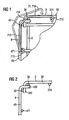
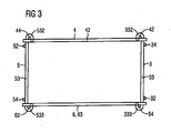
- FIG 1 and 2 show an embodiment of the invention, comprising a base mesh 2 and the side meshes 3 and 4, wherein from side mesh 3, the parallel outer side mesh 34 and inner side mesh 374 and its perpendicular upper side mesh 33 are shown. Furthermore, from side mesh 4, the parallel outer side mesh 42 and inner side mesh 471 and its perpendicular upper side mesh 43 are shown.
- the third side wire 33 of the first side mesh 3 has an end portion 332 which is bent inwards around at least substantially 90° with respect to the third side wire 33.
- the third side wire 43 of the second side mesh 4 has a bent end 432, which is also bent around 90°.
- An angled part 71 can be clipped with its hinged ends 712 and 711 around the forth side wire 34 of the side mesh 3 and the second side wire 42 of the side mesh 4 to hold the side meshes in their upright position.
- the angled part 71 is formed like an angled wire and comprises three at least substantially straight wire sections 713, 714 as well as 715, where the section 713 is at least substantially rectangular with respect to the section 715.
- the ends of section 714 are connected with the ends of sections 713 and 715 in an angle of about 45°.
- the section 713 has another, hinged end 712, whereas the section 715 has another, hinged end 711.
- the hinged end 711 can be clipped over the inner side wire 471 of the side mesh 4 and the second end 712 can be clipped over the inner side wire 374 of side mesh 3, when both side meshes 3 and 4 are in their upright positions.
- FIG 2 shows again, as a detail, a third side wire 33 of the first side mesh 3 which has an end portion 332 bend by 90°.
- the third side wire 43 of the second side mesh 4 has a bent end 432, which is also bent around 90°.
- the forth side wire 34 of the first side mesh 3 is arranged between the third side wire 33 of the first side mesh 3 and, in parallel, the end portion 432 of the third side wire 43 of the side mesh 4.
- the side mesh 42 is arranged between the side wire 43 of the side mesh 4 and, also in parallel, the end portion 332 of the third side wire 33 of the side mesh 3.
- Corresponding angled parts can be clipped over the other upper three edges of the basket.
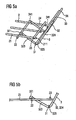
- FIG 3 shows another embodiment of a foldable basket according to the invention, wherein the upper side wires 33, 43, 53 and 63 of the side meshes 3 to 6 can be seen.
- side wires 32 and 34, 42 and 44, 52 and 54 as well as 62 and 64 are shown which are perpendicular and outwards with respect to the respective corresponding upper side wire and which are protruding away from the not shown base mesh 2.
- the upper, third side wire 33 of the first side mesh 3 comprises two looped ends 332 and 333 which are curved inwardly as a half-circle.
- the third, upper side wire 53 of the opposite side mesh 5 comprises two looped ends 532 and 533 which are also curved inwardly as a half-circle.
- the looped end 332 of the third side wire 33 of the first side mesh 3 is clippable over the upper end area of the second side wire 42 of the second side mesh 4.
- the looped end 333 of the third side wire 33 of the first side mesh 3 is clippable over the end area of the forth side wire 64 of the side mesh 6.
- the looped ends 532 and 533 of the third side wire 53 are clippable over the upper end area of the forth side wire 44 of the second side mesh 4 and the upper end area of the second side wire 62 of the second side mesh 6.
- the side meshes 3 and 4 are pushable over and/or into each other against a pre-tension at the side mesh 42 which works as a mutual hooking point to form a mutual connection between side meshes 3 and 4.
- the side meshes 3 and 4 are mutually hooked under tension, which is counterpressed by the connection between the looped side wire 332 and the side wire 42.
- the side meshes 3 and 4 form a spring tension with respect to the base mesh 2, wherein the side meshes 3 and 4 form an outwardly oriented tension, so that the tension is usable for a rigid connection.
- a corresponding connection is existing between the side meshes 3 and 6, 6 and 5 as well as between the side meshes 5 and 4.
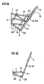
- FIG 5a to 7 show details of a foldable basket according to the invention.
- the figures show a part of a base mesh 2 and a part of a side mesh 3 which are in communication with each other.
- the base mesh 2 comprises a first base wire 21 which is perpendicular to a second base wire 22 and a third base wire 23.
- the base wires 22 and 23 are parallel to each other, whereas the third base wire 23 is, with respect to the not shown center of the base mesh 2, arranged outwards relative to the second base wire 22.
- the side mesh 3 comprises a first side wire 31, which is perpendicular to a second side wire 32.
- the second side wire 32 comprises two segments 323 and 324 between which a bending 325 with an angle of about 90° is arranged.
- the bending 325 surrounds the first side wire 31.
- the segment 323 has a hinged end 321 which encompasses the second base wire 22 when it is hooked over the second base wire 22.
- a forth side wire 34 which is parallel to the second side wire 32 can be seen in FIG 5a , where the forth side wire 34 is of the same form as the second side wire 32. Consequently, it also comprises a looped end 341 which also encompasses the second base wire 22 when it is hooked over the second base wire 22.
- the lower side wire 31 does not necessarily need to be directly adjacent to base wire 23.
- base wire 23 can be located closer to base wire 22 as well.
- Base wire 22 works as a vertical fixation point for the side mesh 3, it guarantees and/or enables the horizontal position of side wire 323.
- base wire 23 is as distant as possible from base wire 22, so that the lever formed by side wire 32 is as long as possible.
- wire 31 does not necessarily need to be bent around wire 31.
- the position of wire 31 regarding wire 324 is at least substantially depending on the geometry of wire end 211. It needs to be in the right position to be able to be clipped over wire end 211.
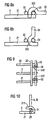
- FIG 5a and FIG 5b show a part of the side mesh 3 in a position, where its hinged side wire ends 321 and 341 are not hinged over the second base wire 22 of the base mesh 2.
- FIG 6a and FIG 6b show a part of the side mesh 3 in a position, where its hinged side wire ends 341 and, not shown, 321, are hinged over the second base wire 22 of the base mesh 2.
- FIG 7 shows parts of the side mesh 3 in an upright position with respect to the base mesh 2.
- the first side wire 31 is clipped over the end portion 211 of the first base wire 21 and the end portion 241 of the forth base wire 24.
- the first side wire 31 is arranged parallel and adjacent to the third base wire 23.
- the first side wire 31 In a tilted position, after clipping the first side wire 31 over the end portion 211 of the first base wire 21 and the end portion 241 of the forth base wire 24, the first side wire 31 could be arranged with distance to the third base wire 23.
- FIG 8a and 8b show a detail of another embodiment of a foldable basket according to the invention with a second side wire 32 of the side mesh 3 and a first base wire 21 of the base mesh 2 from the side of the base mesh 2.
- two parallel base wires 22 and 23 are shown, which are perpendicular with respect to the first base wire 21.
- the base wires 22 and 23 have a distance which is slightly more than the diameter of a side wire.
- the second side wire 32 comprises a hooked end 322 which is formed similar like a question mark with its lower part merging onto the second side wire 32.
- the outer part of the hooked end 322 is curved nearly like a half circle where the end area of the hooked end 322 is directed at least nearly perpendicular with respect to the second side wire 32.
- the hooked end 322 is intended, when a connection with base mesh 2 is to be formed, to be rotated around the third side wire 23 of base mesh 2.
- FIG 8a shows the second side wire 32 in parallel state with respect to the first base wire 21.
- the hooked end 322 can be hooked in between the second base wire 22 and the third base wire 23. Therefore, when the base wire 21 and the side wire 32 are pulled away from each other, the hooked end 322 will hold the two wires together. Substantially, in a translational movement, the side wire 32 can only be moved upwards with respect to the base mesh 2.
- FIG 8b shows the second side wire 32 in perpendicular, upright state with respect to the first base wire 21.
- the hook 322 is now clamped between the second base wire 22 and the third base wire 23 which means that the side wire 32 can be moved translationally in neither direction, only a rotational movement is possible.
- FIG 9 shows the arrangement according to FIG 8b from above the base mesh 2 where, as a further base wire, the forth base wire 24 can be seen which is parallel to the first base wire 21. Another base wire is arranged between the base wires 21 and 24.
- the forth side wire 34 can be seen. It comprises, at its lower end, a hook 342 which is formed like the hook 322.
- the hook 342 is surrounding the base mesh 23 in the same manner like the hook 322.
- FIG 10 shows a principle of another embodiment of the invention where the base mesh 2 is viewed from the side. It can be seen the first base mesh 21 and, perpendicular, the third base mesh 23. Furthermore, the perpendicular side wires 31 and 32 of side mesh 3 can be seen, where side wire 31 is parallel to base mesh 23.
- a hook 212 is arranged.
- the hook 212 starts perpendicular to the first base wire 21 and bends inwards towards the base wire 21, where its outest end is bent into the opposite direction away from the first base wire 21.
- the hook 212 grips around the side mesh 31 and therefore connects the base mesh 2 and the side mesh 3.
- FIG 11 shows a partly assembled basket 1 according to the invention with a base mesh 2 and two separate side meshes 3 and 5 on opposite sides.
- the two remaining opposite side meshes 4 and 6 are connected integrally and bendably or foldably with the base mesh 2.
- the opposite side meshes 3 and 5 are connected with the base mesh 2 by hooks 233 to 236 and well as 253 to 256, respectively.
- a first group 253, 254 of hinges are fixed to the fifth base wire 25 whose openings are oriented to the inside of the base mesh 2.
- the hinges are formed similar like the hinge 212 shown in FIG 10 .
- a second group 255 and 256 of hinges is arranged besides the first group of hinges whose openings are oriented to the outside of the base mesh 2.
- a first group 233, 234 of hinges is fixed to the third base wire 23 whose openings are oriented to the outside of the base mesh 2. Furthermore, a second group 235 and 236 of hinges is arranged beside the first group of hinges whose openings are oriented to the inside of the base mesh 2.
- the side mesh 3 is rotated with respect to base mesh 2.
- the side mesh 3 is positioned with upright orientation with the center of the first, lower side wire 31 over the center of base wire 23, where side wire 31 is rotated with respect to base wire 23 around a rotation axis M which is extending upwardly through the center of side mesh 3.
- the side mesh 5 and the base mesh 2 are connected in the same way.
- FIG 12 shows a part of the base mesh 2 according to FIG 11 with parts of the side meshes 3 and 6 and hinges 233 and 234.
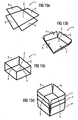
- FIG 13a to 13d show another embodiment of a foldable basket 1 which is, in FIG 13d , stapled with two other baskets 1' and 1''.
- FIG 13a shows a base mesh 2 and four side meshes 3 to 6 wherein the four side meshes 3 to 6 are arranged in a transporting and/or storing orientation.
- the four side meshes 3 to 6 are in the same plane as the base mesh 2.
- FIG 13b shows the foldable basket 1 in an unassembled state, where base 2 and side meshes 3 to 6 are already connected and each side mesh 3 to 6 is tilted with respect to the base mesh 2 from the upright position with an angle of about 30°.
- FIG 13d shows three unassembled baskets 1, 1' and 1'' in a stapled state.
- Each basket 1, 1', 1'' has its side meshes 3 to 6 tilted with respect to the base mesh 2 from the upright position with an angle of about 30° so that the baskets can be stapled easily and space-savingly.
Landscapes
- Rigid Containers With Two Or More Constituent Elements (AREA)
Claims (12)
- Zusammenklappbarer Korb (1) für eine Geschirrspülmaschine, aufweisenda) ein insbesondere im Wesentlichen rechteckiges Grundgitter (2) undb) mindestens zwei, insbesondere vier, klappbare, biegsame oder gelenkig angeordnete Seitengitter (3, 4, 5, 6),
dadurch gekennzeichnet, dassc) jedes zusammenklappbare, biegsame oder gelenkig angeordnete Seitengitter (3, 4, 5, 6) mit dem Grundgitter (2) drehbar, bevorzugt um mindestens ein Scharnierelement, klappbar oder biegsam verbunden oder verbindbar ist,d) wobei jedes Seitengitter (3), ausgehend von einer aufrechten Orientierung des Seitengitters (3), eine obere Kante aufweist, unde) wobei die Seitengitter in ihrer aufrechten Orientierung durch mindestens ein Hakenelement fixiert sind, welches an oder mindestens in der Nähe von mindestens einer oberen Kante der Seitengitter angeordnet ist. - Zusammenklappbarer Korb nach Anspruch 1,a) wobei das Hakenelement ein Befestigungsdraht (71) ist oder einen solchen aufweist,b) wobei bevorzugt der Befestigungsdraht (71) gebogen, bevorzugt um 90°, ist,c) wobei bevorzugt der Befestigungsdraht (71) ein erstes Befestigungselement, bevorzugt einen Haken, als erstes Ende (711) aufweist,d) wobei bevorzugt der Befestigungsdraht (71) ein zweites Befestigungselement, bevorzugt einen Haken oder eine Schnappbiegung, an seinem zweiten Ende (712) aufweist, um ein erstes Seitengitter (3) und ein zweites Seitengitter (4) aneinander zu befestigen.
- Zusammenklappbarer Korb nach einem der vorhergehenden Ansprüche,a) wobei die mindestens zwei Seitengitter (3) entlang ihrer oberen Kanten einen oberen Seitendraht aufweisen,b) wobei die mindestens zwei Seitengitter (3) jeweils mindestens einen senkrechten Seitendraht (371 bis 374) aufweisen, der sich, bevorzugt senkrecht, zum oberen Seitendraht hin und/oder über diesen hinaus erstrecken,c) wobei der obere Seitendraht (33) des oder eines ersten Seitengitters (3) an einem äußeren Ende (332), bevorzugt um 90°, gebogen ist,d) wobei der obere Seitendraht (43) des oder eines zweiten Seitengitters (4) an einem äußeren Ende (432), bevorzugt um 90°, gebogen ist,e) so dass, in der aufrechten Orientierung, der gebogene obere Seitendraht (33) des ersten Seitengitters (3) und der gebogene obere Seitendraht (43) des zweiten Seitengitters (4) einander kreuzen,f) wobei der senkrechte Seitendraht (34) des ersten Seitengitters (3) bevorzugt zwischen dem oberen Seitendraht (33) des ersten Seitengitters (3) und dem gebogenen oberen Seitendrahtende (432) des zweiten Seitengitters (4) angeordnet ist,g) wobei der senkrechte Seitendraht (42) des zweiten Seitengitters (4) bevorzugt zwischen dem oberen Seitendraht (43) des ersten Seitengitters (4) und dem gebogenen oberen Seitendrahtende (332) des ersten Seitengitters (3) angeordnet ist,h) um zu verhindern, dass die Seitengitter auf das Grundgitter (2) fallen.
- Zusammenklappbarer Korb nach einem der vorhergehenden Ansprüche,a) wobei jedes Seitengitter (3) einen oberen Seitendraht entlang seiner oberen Kante aufweist,b) wobei der obere Seitendraht (33) des ersten Seitengitters (3) mindestens ein gelenkig angeordnetes Ende (332) aufweist,c) wo ein zweites Seitengitter (3) mindestens einen senkrechten Seitendraht (42, 64) aufweist, der sich, bevorzugt senkrecht, zum oberen Seitendraht hin und/oder über diesen hinaus erstreckt,d) wobei das gelenkig angeordnete Ende (332) schnappbar über den senkrechten Seitendraht (42) des zweiten Seitengitters (4) ist, um das erste Seitengitter (3) und das zweite Seitengitter (4) in deren aufrechter Orientierung zu fixieren.
- Zusammenklappbarer Korb nach einem der vorhergehenden Ansprüche,a) wobei das mindestens eine Seitengitter (3, 4, 5, 6) in seiner aufrechten Orientierung durch mindestens eine Rastverbindung oder Schnappverbindung gehalten wird,b) wobei bevorzugt mindestens ein Grunddraht oder Seitendraht (31) als Einrast- oder Schnappteil benutzt wird.
- Zusammenklappbarer Korb nach einem der vorhergehenden Ansprüche,a) wobei mindestens zwei Seitengitter (3, 4, 5, 6) über und/oder in einander gegen eine Vorspannung an einem gegenseitigen Einhakpunkt gedrückt werden können, um eine gegenseitige Verbindung zu bilden,b) wobei, in der gegenseitigen Verbindung, die Seitengitter (3, 4, 5, 6) unter Spannung miteinander verhakt sind und/oderc) wobei, in der gegenseitigen Verbindung, die Seitengitter (3, 4, 5, 6) bezogen auf das Grundgitter (2) eine Federspannung erzeugen, wobei die Seitengitter insbesondere eine nach außen gerichtete Spannung bilden, so dass die Spannung bevorzugt für eine starre Verbindung ausgenutzt werden kann.
- Zusammenklappbarer Korb nach einem der vorhergehenden Ansprüche,a) wobei das Grundgitter (2) Folgendes aufweist:a1) einen ersten Grunddraht (21) an einer ersten Kante des Grundgitters (2) mit einem ersten Grunddrahtende (211),a2) einen zweiten Grunddraht (22), der senkrecht zum ersten Grunddraht (21) angeordnet ist,a3) einen dritten Grunddraht (23) an einer zweiten Kante gegenüber der ersten Kante des Grundgitters (2), der parallel zum zweiten Grunddraht (22) verläuft,a4) wobei der dritte Grunddraht, bezogen auf das Grundgitter (2), im Hinblick auf den zweiten Grunddraht (22) nach außen angeordnet ist,b) wobei das mindestens eine Seitengitter (3) Folgendes aufweist:b1) einen ersten, unteren Seitendraht (31) an einer ersten, unteren Kante des Seitengitters (3),b2) einen zweiten Seitendraht (32) an einer zweiten Kante des Seitengitters (3),b3) einen dritten, oberen Seitendraht (33) an einer dritten, oberen Kante des Seitengitters, parallel und gegenüber liegend zum ersten Seitendraht (31) und senkrecht zum zweiten Seitendraht (32),b3) einen vierten Seitendraht (34) an einer vierten Kante des Seitengitters, senkrecht zum ersten Seitendraht (31) und bevorzugt parallel und gegenüber liegend zum zweiten Seitendraht (32),c) wobei bevorzugt der zusammenklappbare Korb mindestens ein erstes (3) und ein zweites (4) Seitengitter aufweist, wobei das erste Seitengitter (3), im zusammengesetzten Zustand, mindestens im Wesentlichen senkrecht in Bezug auf das zweite Seitengitter (4) und in Bezug auf das Grundgitter (2) ist, und/oderd) wobei bevorzugt der erste Seitendraht (31) des ersten Seitengitters (3) drehbar oder klappbar oder biegbar mit dem dritten Grunddraht (23) des Grundgitters (2) verbunden ist.
- Zusammenklappbarer Korb nach einem der vorhergehenden Ansprüche,a) wobei das Seitengitter einen unteren Seitendraht (31) an seiner unteren, seiner oberen gegenüber liegenden Kante aufweist,b) wobei der untere Seitendraht (31) schnappbar über mindestens ein Grunddrahtende (211) zur Befestigung des Seitengitters in der aufrechten Orientierung sm Grundgitter (2) angeordnet ist,c) wobei bevorzugt ein weiterer Grunddraht (22) als ein Befestigungspunkt für das Seitengitter (3) in dessen aufrechter Position dient, und/oderd) wobei bevorzugt der untere Seitendraht (31) an einem anderen Seitendraht (32) befestigt ist, welcher sich senkrecht zum oberen Seitendraht (33) hin oder hinter denselben erstreckt,d1) wobei bevorzugt der andere Seitendraht (32) in einem Winkel, insbesondere mindestens im Wesentlichen senkrecht, gebogen ist, und/oderd2) wobei bevorzugt der andere Seitendraht (32) ein gelenkig angeordnetes Ende (321) aufweist, welches einen oder den weiteren Grunddraht (22) umschließt, welcher sich bevorzugt parallel zu einem anderen Grunddraht (23) erstreckt.
- Zusammenklappbarer Korb nach einem der vorhergehenden Ansprüche,a) wobei der zusammenklappbare Korb (1) vier Seitengitter (3, 4, 5, 6) aufweist,b) wobei mindestens zwei Seitengitter (4, 6), insbesondere auf einander gegenüber liegenden Seiten des Grundgitters (2), biegbar mit dem Grundgitter (2) verbunden sind, und/oderc) wobei mindestens zwei Seitengitter (3, 5), insbesondere auf den verbliebenen, einander gegenüber liegenden Seiten des Grundgitters (2), drehbar mit dem Grundgitter verbunden sind.
- Zusammenklappbarer Korb nach einem der vorhergehenden Ansprüche, wobei mindestens zwei Seitengitter (4, 6) wie folgt angeordnet sind oder angeordnet werden könnena) mindestens im Wesentlichen in der gleichen Ebene wie das Grundgitter (2), bevorzugt für Lagerung und Transport, oderb) gewinkelt in Bezug auf das Grundgitter (2).
- Zusammenklappbarer Korb nach einem der vorhergehenden Ansprüche,a) wobei die drehbare Verbindung zwischen dem Grundgitter (2) und dem mindestens einen Seitengitter (3, 5) ausgeführt ist durch eine erste (253, 254) und eine zweite (255, 256) Gruppe von Scharnieren,b) wobei die erste Gruppe von Scharnieren (253, 254) Scharniere aufweist, die zur Innenseite des Grundgitters (2) hin offen sind, und die zweite Gruppe von Scharnieren (255, 256) Scharniere aufweist, die zur Außenseite des Grundgitters (2) hin offen sind.
- Zusammenklappbarer Korb nach einem der vorhergehenden Ansprüche,a) wobei mindestens ein Seitengitter (3) mindestens einen Seitendraht (32, 34) aufweist, der sich, bevorzugt senkrecht, zur oberen Kante des Seitengitters (3) hin und/oder über diese hinaus erstreckt,b) wobei der Seitendraht (32) des Seitengitters (3) mindestens ein gelenkig angeordnetes Ende (322) aufweist,c) wobei das gelenkig angeordnete Ende (322) gelenkt oder lenkbar zwischen zwei Grunddrähten (22, 23) innerhalb eines mindestens im Wesentlichen parallelen Bereichs angeordnet ist,d) wobei bevorzugt die zwei Grunddrähte (22, 23) entlang ihres mindestens im Wesentlichen parallelen Bereichs einen solchen Abstand zueinander aufweisen, dass das gelenkig angeordnete Ende (322) zwischen diese hinein passt, so dass sie zwei Anschlagelemente für das gelenkig angeordnete Ende (322) bilden, wenn sie in der aufrechten Position angeordnet werden, wo sich die zwei Grunddrähte (22, 23) bevorzugt mindestens im Wesentlichen direkt neben dem gelenkig angeordneten Ende (322) auf gegenüber einander liegenden Seiten befinden.
Priority Applications (2)
| Application Number | Priority Date | Filing Date | Title |
|---|---|---|---|
| PL08019219T PL2181639T3 (pl) | 2008-11-03 | 2008-11-03 | Składany kosz, w szczególności składany kosz do zmywarki |
| EP08019219A EP2181639B1 (de) | 2008-11-03 | 2008-11-03 | Zusammenklappbarer Korb, insbesondere zusammenklappbarer Spülmaschinenkorb |
Applications Claiming Priority (1)
| Application Number | Priority Date | Filing Date | Title |
|---|---|---|---|
| EP08019219A EP2181639B1 (de) | 2008-11-03 | 2008-11-03 | Zusammenklappbarer Korb, insbesondere zusammenklappbarer Spülmaschinenkorb |
Publications (2)
| Publication Number | Publication Date |
|---|---|
| EP2181639A1 EP2181639A1 (de) | 2010-05-05 |
| EP2181639B1 true EP2181639B1 (de) | 2012-10-17 |
Family
ID=40613140
Family Applications (1)
| Application Number | Title | Priority Date | Filing Date |
|---|---|---|---|
| EP08019219A Not-in-force EP2181639B1 (de) | 2008-11-03 | 2008-11-03 | Zusammenklappbarer Korb, insbesondere zusammenklappbarer Spülmaschinenkorb |
Country Status (2)
| Country | Link |
|---|---|
| EP (1) | EP2181639B1 (de) |
| PL (1) | PL2181639T3 (de) |
Families Citing this family (5)
| Publication number | Priority date | Publication date | Assignee | Title |
|---|---|---|---|---|
| CN105996951B (zh) * | 2016-07-08 | 2019-01-29 | 珠海格力电器股份有限公司 | 筷篮组件及洗碗机 |
| DE102017201227B3 (de) | 2017-01-26 | 2018-03-29 | BSH Hausgeräte GmbH | Haushaltsgeschirrspülmaschine |
| CN106859567B (zh) * | 2017-03-07 | 2020-02-07 | 佛山市顺德区美的洗涤电器制造有限公司 | 家用电器、用于洗碗机的碗篮及收纳装置 |
| CN108185947A (zh) * | 2018-02-07 | 2018-06-22 | 宁波美高厨具有限公司 | 带果蔬篮的水槽式洗碗机 |
| KR102313446B1 (ko) * | 2019-12-13 | 2021-10-14 | 이유림 | 식기 안착부의 승강 기능을 구비한 초음파 식기세척기 |
Family Cites Families (5)
| Publication number | Priority date | Publication date | Assignee | Title |
|---|---|---|---|---|
| US2524900A (en) * | 1947-05-19 | 1950-10-10 | Einhorn Fannie | Collapsible wire basket |
| US5332105A (en) * | 1992-10-13 | 1994-07-26 | John Stanfield | Portable dish rack |
| IT251280Y1 (it) | 2000-02-21 | 2003-11-19 | Electrolux Zanussi Elettrodome | Cesto perfezionato per articoli da lavare in una lavastoviglie comepiatti e bicchieri |
| US7383846B2 (en) * | 2003-07-01 | 2008-06-10 | General Electric Company | Dishwasher basket |
| DE102004060951A1 (de) | 2004-12-17 | 2006-06-29 | BSH Bosch und Siemens Hausgeräte GmbH | Geschirrkorb für eine Geschirrspülmaschine |
-
2008
- 2008-11-03 EP EP08019219A patent/EP2181639B1/de not_active Not-in-force
- 2008-11-03 PL PL08019219T patent/PL2181639T3/pl unknown
Also Published As
| Publication number | Publication date |
|---|---|
| PL2181639T3 (pl) | 2013-03-29 |
| EP2181639A1 (de) | 2010-05-05 |
Similar Documents
| Publication | Publication Date | Title |
|---|---|---|
| EP2181639A1 (de) | Zusammenklappbarer Korb, insbesondere zusammenklappbarer Spülmaschinenkorb | |
| US8757419B2 (en) | Crockery basket comprising height-adjustable racks | |
| RU2479901C2 (ru) | Кабелепрокладочное устройство | |
| US10806258B2 (en) | Utility rack having end supports with folding cross-members | |
| US5097971A (en) | Stackable and collapsible shelf assembly | |
| US20150305297A1 (en) | Collapsible animal enclosure | |
| EP2181638B1 (de) | Zusammenklappbarer Spülmaschinenkorb | |
| CN104825112A (zh) | 用于洗碗机的碗篮组件及具有其的洗碗机 | |
| US20150196189A1 (en) | Dishwasher appliance | |
| WO2009062052A1 (en) | Shelf accessory for a dishwasher rack | |
| EP2554095B1 (de) | Geschirrkorb einer Geschirrspülmaschine, mit verschwenkbaren, zusammenklappbaren Anlageelementen | |
| CN107024087B (zh) | 折叠式干燥装置 | |
| US20110017246A1 (en) | Crockery basket and dishwasher | |
| CN204618160U (zh) | 用于洗碗机的碗篮组件及具有其的洗碗机 | |
| US20060289711A1 (en) | Plastic pot hanger and mould for manufacture thereof | |
| US8123049B2 (en) | Pot stand | |
| US6892895B2 (en) | Collapsible container | |
| KR101865581B1 (ko) | 조립식 책상 프레임 | |
| EP2067431B1 (de) | Geschirrkorb für Geschirrspülmaschine mit Flaschenhalter | |
| EP2770873B1 (de) | Trägerstruktur für tische und tisch mit dieser trägerstruktur | |
| KR101262079B1 (ko) | 에어컨 실외기 설치대 | |
| EP2373944B1 (de) | Einen flaschenträger umfassende kühlvorrichtung | |
| KR20040023110A (ko) | 식기세척기용 랙어셈블리 | |
| US20110012487A1 (en) | Crockery basket and dishwasher | |
| AU2009253831B2 (en) | Wine rack |
Legal Events
| Date | Code | Title | Description |
|---|---|---|---|
| PUAI | Public reference made under article 153(3) epc to a published international application that has entered the european phase |
Free format text: ORIGINAL CODE: 0009012 |
|
| AK | Designated contracting states |
Kind code of ref document: A1 Designated state(s): AT BE BG CH CY CZ DE DK EE ES FI FR GB GR HR HU IE IS IT LI LT LU LV MC MT NL NO PL PT RO SE SI SK TR |
|
| AX | Request for extension of the european patent |
Extension state: AL BA MK RS |
|
| 17P | Request for examination filed |
Effective date: 20101104 |
|
| AKX | Designation fees paid |
Designated state(s): AT BE BG CH CY CZ DE DK EE ES FI FR GB GR HR HU IE IS IT LI LT LU LV MC MT NL NO PL PT RO SE SI SK TR |
|
| 17Q | First examination report despatched |
Effective date: 20110111 |
|
| RAP1 | Party data changed (applicant data changed or rights of an application transferred) |
Owner name: ELECTROLUX HOME PRODUCTS CORPORATION N.V. |
|
| RAP1 | Party data changed (applicant data changed or rights of an application transferred) |
Owner name: ELECTROLUX HOME PRODUCTS CORPORATION N.V. |
|
| GRAP | Despatch of communication of intention to grant a patent |
Free format text: ORIGINAL CODE: EPIDOSNIGR1 |
|
| GRAS | Grant fee paid |
Free format text: ORIGINAL CODE: EPIDOSNIGR3 |
|
| GRAA | (expected) grant |
Free format text: ORIGINAL CODE: 0009210 |
|
| AK | Designated contracting states |
Kind code of ref document: B1 Designated state(s): AT BE BG CH CY CZ DE DK EE ES FI FR GB GR HR HU IE IS IT LI LT LU LV MC MT NL NO PL PT RO SE SI SK TR |
|
| REG | Reference to a national code |
Ref country code: GB Ref legal event code: FG4D |
|
| REG | Reference to a national code |
Ref country code: CH Ref legal event code: EP |
|
| REG | Reference to a national code |
Ref country code: IE Ref legal event code: FG4D |
|
| REG | Reference to a national code |
Ref country code: AT Ref legal event code: REF Ref document number: 579500 Country of ref document: AT Kind code of ref document: T Effective date: 20121115 |
|
| REG | Reference to a national code |
Ref country code: DE Ref legal event code: R096 Ref document number: 602008019383 Country of ref document: DE Effective date: 20121213 |
|
| REG | Reference to a national code |
Ref country code: AT Ref legal event code: MK05 Ref document number: 579500 Country of ref document: AT Kind code of ref document: T Effective date: 20121017 |
|
| REG | Reference to a national code |
Ref country code: NL Ref legal event code: VDEP Effective date: 20121017 |
|
| REG | Reference to a national code |
Ref country code: LT Ref legal event code: MG4D |
|
| REG | Reference to a national code |
Ref country code: PL Ref legal event code: T3 |
|
| PG25 | Lapsed in a contracting state [announced via postgrant information from national office to epo] |
Ref country code: HR Free format text: LAPSE BECAUSE OF FAILURE TO SUBMIT A TRANSLATION OF THE DESCRIPTION OR TO PAY THE FEE WITHIN THE PRESCRIBED TIME-LIMIT Effective date: 20121017 Ref country code: LT Free format text: LAPSE BECAUSE OF FAILURE TO SUBMIT A TRANSLATION OF THE DESCRIPTION OR TO PAY THE FEE WITHIN THE PRESCRIBED TIME-LIMIT Effective date: 20121017 Ref country code: IS Free format text: LAPSE BECAUSE OF FAILURE TO SUBMIT A TRANSLATION OF THE DESCRIPTION OR TO PAY THE FEE WITHIN THE PRESCRIBED TIME-LIMIT Effective date: 20130217 Ref country code: SE Free format text: LAPSE BECAUSE OF FAILURE TO SUBMIT A TRANSLATION OF THE DESCRIPTION OR TO PAY THE FEE WITHIN THE PRESCRIBED TIME-LIMIT Effective date: 20121017 Ref country code: NL Free format text: LAPSE BECAUSE OF FAILURE TO SUBMIT A TRANSLATION OF THE DESCRIPTION OR TO PAY THE FEE WITHIN THE PRESCRIBED TIME-LIMIT Effective date: 20121017 Ref country code: FI Free format text: LAPSE BECAUSE OF FAILURE TO SUBMIT A TRANSLATION OF THE DESCRIPTION OR TO PAY THE FEE WITHIN THE PRESCRIBED TIME-LIMIT Effective date: 20121017 Ref country code: ES Free format text: LAPSE BECAUSE OF FAILURE TO SUBMIT A TRANSLATION OF THE DESCRIPTION OR TO PAY THE FEE WITHIN THE PRESCRIBED TIME-LIMIT Effective date: 20130128 Ref country code: NO Free format text: LAPSE BECAUSE OF FAILURE TO SUBMIT A TRANSLATION OF THE DESCRIPTION OR TO PAY THE FEE WITHIN THE PRESCRIBED TIME-LIMIT Effective date: 20130117 |
|
| PG25 | Lapsed in a contracting state [announced via postgrant information from national office to epo] |
Ref country code: GR Free format text: LAPSE BECAUSE OF FAILURE TO SUBMIT A TRANSLATION OF THE DESCRIPTION OR TO PAY THE FEE WITHIN THE PRESCRIBED TIME-LIMIT Effective date: 20130118 Ref country code: PT Free format text: LAPSE BECAUSE OF FAILURE TO SUBMIT A TRANSLATION OF THE DESCRIPTION OR TO PAY THE FEE WITHIN THE PRESCRIBED TIME-LIMIT Effective date: 20130218 Ref country code: SI Free format text: LAPSE BECAUSE OF FAILURE TO SUBMIT A TRANSLATION OF THE DESCRIPTION OR TO PAY THE FEE WITHIN THE PRESCRIBED TIME-LIMIT Effective date: 20121017 Ref country code: BE Free format text: LAPSE BECAUSE OF FAILURE TO SUBMIT A TRANSLATION OF THE DESCRIPTION OR TO PAY THE FEE WITHIN THE PRESCRIBED TIME-LIMIT Effective date: 20121017 Ref country code: LV Free format text: LAPSE BECAUSE OF FAILURE TO SUBMIT A TRANSLATION OF THE DESCRIPTION OR TO PAY THE FEE WITHIN THE PRESCRIBED TIME-LIMIT Effective date: 20121017 |
|
| PG25 | Lapsed in a contracting state [announced via postgrant information from national office to epo] |
Ref country code: AT Free format text: LAPSE BECAUSE OF FAILURE TO SUBMIT A TRANSLATION OF THE DESCRIPTION OR TO PAY THE FEE WITHIN THE PRESCRIBED TIME-LIMIT Effective date: 20121017 |
|
| PG25 | Lapsed in a contracting state [announced via postgrant information from national office to epo] |
Ref country code: BG Free format text: LAPSE BECAUSE OF FAILURE TO SUBMIT A TRANSLATION OF THE DESCRIPTION OR TO PAY THE FEE WITHIN THE PRESCRIBED TIME-LIMIT Effective date: 20130117 Ref country code: CZ Free format text: LAPSE BECAUSE OF FAILURE TO SUBMIT A TRANSLATION OF THE DESCRIPTION OR TO PAY THE FEE WITHIN THE PRESCRIBED TIME-LIMIT Effective date: 20121017 Ref country code: SK Free format text: LAPSE BECAUSE OF FAILURE TO SUBMIT A TRANSLATION OF THE DESCRIPTION OR TO PAY THE FEE WITHIN THE PRESCRIBED TIME-LIMIT Effective date: 20121017 Ref country code: DK Free format text: LAPSE BECAUSE OF FAILURE TO SUBMIT A TRANSLATION OF THE DESCRIPTION OR TO PAY THE FEE WITHIN THE PRESCRIBED TIME-LIMIT Effective date: 20121017 Ref country code: EE Free format text: LAPSE BECAUSE OF FAILURE TO SUBMIT A TRANSLATION OF THE DESCRIPTION OR TO PAY THE FEE WITHIN THE PRESCRIBED TIME-LIMIT Effective date: 20121017 |
|
| REG | Reference to a national code |
Ref country code: IE Ref legal event code: MM4A |
|
| PLBE | No opposition filed within time limit |
Free format text: ORIGINAL CODE: 0009261 |
|
| STAA | Information on the status of an ep patent application or granted ep patent |
Free format text: STATUS: NO OPPOSITION FILED WITHIN TIME LIMIT |
|
| PG25 | Lapsed in a contracting state [announced via postgrant information from national office to epo] |
Ref country code: RO Free format text: LAPSE BECAUSE OF FAILURE TO SUBMIT A TRANSLATION OF THE DESCRIPTION OR TO PAY THE FEE WITHIN THE PRESCRIBED TIME-LIMIT Effective date: 20121017 |
|
| 26N | No opposition filed |
Effective date: 20130718 |
|
| PG25 | Lapsed in a contracting state [announced via postgrant information from national office to epo] |
Ref country code: IE Free format text: LAPSE BECAUSE OF NON-PAYMENT OF DUE FEES Effective date: 20121103 |
|
| REG | Reference to a national code |
Ref country code: DE Ref legal event code: R097 Ref document number: 602008019383 Country of ref document: DE Effective date: 20130718 |
|
| PG25 | Lapsed in a contracting state [announced via postgrant information from national office to epo] |
Ref country code: CY Free format text: LAPSE BECAUSE OF FAILURE TO SUBMIT A TRANSLATION OF THE DESCRIPTION OR TO PAY THE FEE WITHIN THE PRESCRIBED TIME-LIMIT Effective date: 20121017 Ref country code: MT Free format text: LAPSE BECAUSE OF FAILURE TO SUBMIT A TRANSLATION OF THE DESCRIPTION OR TO PAY THE FEE WITHIN THE PRESCRIBED TIME-LIMIT Effective date: 20121017 |
|
| PG25 | Lapsed in a contracting state [announced via postgrant information from national office to epo] |
Ref country code: MC Free format text: LAPSE BECAUSE OF NON-PAYMENT OF DUE FEES Effective date: 20121130 |
|
| PG25 | Lapsed in a contracting state [announced via postgrant information from national office to epo] |
Ref country code: LU Free format text: LAPSE BECAUSE OF NON-PAYMENT OF DUE FEES Effective date: 20121103 |
|
| PG25 | Lapsed in a contracting state [announced via postgrant information from national office to epo] |
Ref country code: HU Free format text: LAPSE BECAUSE OF FAILURE TO SUBMIT A TRANSLATION OF THE DESCRIPTION OR TO PAY THE FEE WITHIN THE PRESCRIBED TIME-LIMIT Effective date: 20081103 |
|
| PGFP | Annual fee paid to national office [announced via postgrant information from national office to epo] |
Ref country code: FR Payment date: 20141119 Year of fee payment: 7 Ref country code: GB Payment date: 20141119 Year of fee payment: 7 |
|
| GBPC | Gb: european patent ceased through non-payment of renewal fee |
Effective date: 20151103 |
|
| REG | Reference to a national code |
Ref country code: FR Ref legal event code: ST Effective date: 20160729 |
|
| PG25 | Lapsed in a contracting state [announced via postgrant information from national office to epo] |
Ref country code: GB Free format text: LAPSE BECAUSE OF NON-PAYMENT OF DUE FEES Effective date: 20151103 |
|
| PG25 | Lapsed in a contracting state [announced via postgrant information from national office to epo] |
Ref country code: FR Free format text: LAPSE BECAUSE OF NON-PAYMENT OF DUE FEES Effective date: 20151130 |
|
| PGFP | Annual fee paid to national office [announced via postgrant information from national office to epo] |
Ref country code: DE Payment date: 20191121 Year of fee payment: 12 |
|
| PGFP | Annual fee paid to national office [announced via postgrant information from national office to epo] |
Ref country code: PL Payment date: 20191024 Year of fee payment: 12 Ref country code: IT Payment date: 20191128 Year of fee payment: 12 |
|
| PGFP | Annual fee paid to national office [announced via postgrant information from national office to epo] |
Ref country code: CH Payment date: 20191121 Year of fee payment: 12 Ref country code: TR Payment date: 20191028 Year of fee payment: 12 |
|
| REG | Reference to a national code |
Ref country code: DE Ref legal event code: R119 Ref document number: 602008019383 Country of ref document: DE |
|
| REG | Reference to a national code |
Ref country code: CH Ref legal event code: PL |
|
| PG25 | Lapsed in a contracting state [announced via postgrant information from national office to epo] |
Ref country code: LI Free format text: LAPSE BECAUSE OF NON-PAYMENT OF DUE FEES Effective date: 20201130 Ref country code: CH Free format text: LAPSE BECAUSE OF NON-PAYMENT OF DUE FEES Effective date: 20201130 |
|
| PG25 | Lapsed in a contracting state [announced via postgrant information from national office to epo] |
Ref country code: IT Free format text: LAPSE BECAUSE OF NON-PAYMENT OF DUE FEES Effective date: 20201103 |
|
| PG25 | Lapsed in a contracting state [announced via postgrant information from national office to epo] |
Ref country code: DE Free format text: LAPSE BECAUSE OF NON-PAYMENT OF DUE FEES Effective date: 20210601 |
|
| PG25 | Lapsed in a contracting state [announced via postgrant information from national office to epo] |
Ref country code: TR Free format text: LAPSE BECAUSE OF NON-PAYMENT OF DUE FEES Effective date: 20201103 |
|
| PG25 | Lapsed in a contracting state [announced via postgrant information from national office to epo] |
Ref country code: PL Free format text: LAPSE BECAUSE OF NON-PAYMENT OF DUE FEES Effective date: 20201103 |