EP2180739A1 - Coordination d'allocation de resources radio dans dans un système radio macro-/microcellulaire - Google Patents
Coordination d'allocation de resources radio dans dans un système radio macro-/microcellulaire Download PDFInfo
- Publication number
- EP2180739A1 EP2180739A1 EP08018665A EP08018665A EP2180739A1 EP 2180739 A1 EP2180739 A1 EP 2180739A1 EP 08018665 A EP08018665 A EP 08018665A EP 08018665 A EP08018665 A EP 08018665A EP 2180739 A1 EP2180739 A1 EP 2180739A1
- Authority
- EP
- European Patent Office
- Prior art keywords
- base
- station transceiver
- radio resources
- information
- radio
- Prior art date
- Legal status (The legal status is an assumption and is not a legal conclusion. Google has not performed a legal analysis and makes no representation as to the accuracy of the status listed.)
- Granted
Links
Images


Classifications
-
- H—ELECTRICITY
- H04—ELECTRIC COMMUNICATION TECHNIQUE
- H04W—WIRELESS COMMUNICATION NETWORKS
- H04W16/00—Network planning, e.g. coverage or traffic planning tools; Network deployment, e.g. resource partitioning or cells structures
- H04W16/24—Cell structures
- H04W16/32—Hierarchical cell structures
-
- H—ELECTRICITY
- H04—ELECTRIC COMMUNICATION TECHNIQUE
- H04W—WIRELESS COMMUNICATION NETWORKS
- H04W16/00—Network planning, e.g. coverage or traffic planning tools; Network deployment, e.g. resource partitioning or cells structures
- H04W16/02—Resource partitioning among network components, e.g. reuse partitioning
- H04W16/10—Dynamic resource partitioning
-
- H—ELECTRICITY
- H04—ELECTRIC COMMUNICATION TECHNIQUE
- H04W—WIRELESS COMMUNICATION NETWORKS
- H04W84/00—Network topologies
- H04W84/02—Hierarchically pre-organised networks, e.g. paging networks, cellular networks, WLAN [Wireless Local Area Network] or WLL [Wireless Local Loop]
- H04W84/04—Large scale networks; Deep hierarchical networks
- H04W84/042—Public Land Mobile systems, e.g. cellular systems
- H04W84/045—Public Land Mobile systems, e.g. cellular systems using private Base Stations, e.g. femto Base Stations, home Node B
-
- H—ELECTRICITY
- H04—ELECTRIC COMMUNICATION TECHNIQUE
- H04W—WIRELESS COMMUNICATION NETWORKS
- H04W84/00—Network topologies
- H04W84/02—Hierarchically pre-organised networks, e.g. paging networks, cellular networks, WLAN [Wireless Local Area Network] or WLL [Wireless Local Loop]
- H04W84/10—Small scale networks; Flat hierarchical networks
- H04W84/105—PBS [Private Base Station] network
Definitions
- the present invention is in the field of mobile communication systems, especially in networks utilizing hierarchical cell structures.
- Radio resources for example, frequencies in terms of carriers or subcarriers, time slots, spreading codes or sequences, interleaving sequences, spatial subchannels, etc.
- frequencies in terms of carriers or subcarriers for example, frequencies in terms of carriers or subcarriers, time slots, spreading codes or sequences, interleaving sequences, spatial subchannels, etc.
- network topology is changing or advancing to hierarchical structures.
- Present systems also allow a deployment of so-called micro, pico and/or femto cells which are small radio cells deployed on top of regular radio cells, for example for covering home environments.
- FUE Femto-cell User Equipment
- MUE Macro-cell User Equipment
- FUE Femto-cell User Equipment
- modern networks allow deployment of small base-stations, i.e. FUEs, which can be used in home environments. This enables usage of regular cell phones or mobile devices in the home environment as well.
- FUEs cannot be efficiently coordinated by the operators of mobile communication systems, problems with interference coordination and mitigation arise.
- FUEs are not directly connected to the backbone of mobile communication systems, preventing seamless connection to, for example, the control plane of the communication network.
- Femto-cells are mini plug-and-play home base-stations that share radio resources with macro-cells.
- MBS Femto-cell Base-Station
- MBS Macro-cell Base-Station
- the object is achieved by a base-station transceiver according to claim 1, a method for communicating according to claim 7, a base-station transceiver according to claim 10 and a method for communicating according to claim 15.
- the present invention is based on the finding that resource allocation between macro- and femto-cells can be coordinated.
- Direct signalling may be employed in embodiments, by, for example, using conventional messages which may be extended. Signalling may for example be carried out through a backbone network or through the air-interface. In other embodiments indirect signalling may be utilized, based on the finding that femto-cell base-stations may overhear or eavesdrop interference coordination messages between macro-cell base-stations.
- interference coordination or mitigation between macro- and femto-cells can be carried out by providing femto-cells with an information on which resources it shall use or which resources are occupied by either other femto-cells or a macro-cell. Provision of such information may by dedicated and/or explicit, i.e. a message containing such information may be directed directly to a femto-cell, e.g. by means of an unambiguous addressing.
- Provision of such information may be implicit and/or broadcast or addressed to a third cell, the femto-cell may then overhear, eavesdrop or sniff on a communication between a macro-cell and any other cell and determine interference coordination between them, based on which it may coordinate the resources it uses by its own.
- the other cell, to which the information may actually be addressed can be another macro-cell or another femto-cell.
- femto-cells may still share resources with macro-cells and can still be used to enhance, for example, the coverage of LTE or LTE-A in home environments. Interference due to femto-cells can be coordinated by embodiments with advantages arising from a higher system capacity and better service quality.
- Embodiments are based on the finding that spatial separation between MUEs and FUEs sharing the same resources is beneficial for interference reduction. Spatial separation can therefore be utilized for interference coordination.
- the spatial separation can, for example, be achieved by allocating the resources with the assistance of signalling messages from MBS to FBS, in which resources that are e.g. used by MUEs close to specific FBS are indicated so to prevent FBS from reusing such resources.
- Embodiments may have minimal or limited impact on existing standards, for example, in terms of messages or messaging within LTE.
- embodiments may be employed in cellular systems, which utilize femto-cells.
- Embodiments may address resource allocation in the uplink, as well as in the downlink.
- interference coordination may be carried out by embodiments for both transmission directions, i.e., for the uplink and the downlink, the reverse link or the forward link respectively. Interference coordination can be established between femto- and macro-cells and between FUE and MUE.
- base-station and base station transceiver as well as mobile, mobile terminal, transceiver station, user equipment are used synonymously.
- base-station transceiver 100 or other base-station transceiver 100 refers to a macro-cell or MBS and the term base-station transceiver 200 or second base-station transceiver 200 refers to a femto-cell or FBS.
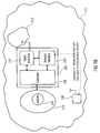
- Fig. 1a illustrates an embodiment of a base-station transceiver 100 being operative in a mobile communication system.
- GSM Global System for Mobile Communications
- 3GPP Third Generation Partnership Project
- UMTS Universal Mobile Communication System
- WCDMA Wideband CDMA
- LTE Long Term Evolution-A, etc.
- the base-station transceiver 100 of Fig. 1a comprises a radio interface 110 adapted for having a first coverage area 112 surrounding a second coverage area 212 of a second base-station transceiver 200.
- a hierarchical cell structure may be established and the embodiment may be adapted for establishing an umbrella cell, i.e., a macro-cell that overlays at least one femto-cell according to coverage areas 112 and 212.
- the embodiment of the base-station transceiver 100 further comprises communication unit 120 being adapted for communicating within the mobile communication system using the radio interface 110 and a first portion 141 of the radio resources from a pool 140 of radio resources of the mobile communication system, the communication unit 120 being further adapted for receiving an information on an identification and an information on an accessibility of the second base-station transceiver 200.
- the communication unit 120 communicates using the radio interface 110 within the mobile communication system.
- radio resources all kinds of radio resources may be utilized in embodiments, i.e., one of the group of e.g. a transmission power, a carrier, a subcarrier, a frequency, a code, timeslot, a spatial subchannel, a transmit or receive antenna, a spreading or channelization code, a scrambling code, an interleaving sequence etc., may be utilized by the base-station transceiver 100 for communicating through the radio interface 110 in the mobile communication system.
- radio resources are summarized in the pool 140 of radio resources, where all radio resources used by the mobile communication system may be gathered. In order to prevent critical interference conditions in the mobile communication system, the radio resources from the pool 140 of radio resources may be coordinated.
- the communication unit 120 is adapted for receiving information on an identification that may identify another network node, for example, a FBS and/or an FUE as the second base-station transceiver 200.
- the information may be directly received from the device identified, in embodiments, however, other devices as for example mobile devices may be configured for carrying out measurements within the mobile communication system, which in turn are, for example, reported to the present base-station transceiver 100.
- the base-station transceiver 100 further comprises a controller 130, which is adapted for the controlling of the first portion 141 of radio resources and for determining a second portion 142 of radio resources based on the pool 140 of radio resources, the information on the identification and the information on the accessibility.
- the second portion 142 of radio resources is such that a mutual interference between the second base-station transceiver 200 using the second portion 142 of radio resources and the base-station transceiver 100 using the first portion 141 of the radio resources is reduced.
- the communication unit 120 is further adapted for communicating an information on the first portion 141 and/or the second portion 142 of radio resources to the second base-station transceiver 200.
- femto-cells or second base-station transceivers 200 there may be open-access femto-cells or second base-station transceivers 200, to which mobile stations are allowed to establish and to hand-over to.
- Other femto-cells or second base-station transceivers 200 may be closed-access femto-cells as e.g. in home environments, i.e. only selected mobile stations may be able to establish with a closed-access femto-cell.
- both kinds of femto-cells or second base-station transceivers 200 may be interference or resource coordinated by a base-station transceiver 100, i.e. an MBS or macro-cell.
- interference coordination with closed-access femto-cells may be more critical as a MUE being close to a FBS is not able to hand-over to the FBS. Therewith, interference is more severe when the MUE uses the same radio resource as a FUE. If such a FBS was an open-access FBS, said MUE could hand-over to the FBS and interference at the FBS caused by a close-by MUE could be avoided. Therefore focus of embodiments may be on closed-access FBS, however, embodiments are not limited thereto.
- the information on the accessibility may be provided implicitly with the information on the identification, in other words, once an information on an identification of a femto-cell or second base-station transceiver 200 is available at the base-station transceiver 100, the information on accessibility could be derived from a list of femto-cells or second base-station transceivers 200.
- second base-station transceivers 200 may have a certain form of identification, which may be unique, however, identifies the FBS or second base-station transceiver 200 as an open-access or closed-access FBS.
- the MBS may receive measurement reports for example from MUEs, which are configured thereto and receive reference signals from a FBS. The MUE may try to access the FBS or establish and report if such attempt has failed, i.e. the information on accessibility may be, in some embodiments, a report on a failed access attempt of a MUE.
- the controller 130 is adapted for coordinating interference by determining a first portion 141 and a second portion 142 of radio resources.
- the first portion 141 and the second portion 142 may be such that an interference is reduced when the base-station transceiver 100, using the first portion 141 of radio resources, communicates simultaneously with the second base-station transceiver 200, using the second portion 142 of radio resources. Such communication may be in the uplink and/or in the downlink.
- the first portion 141 of radio resources and the second portion 142 of radio resources may be such that they are orthogonal, i.e., that no interference or collisions may be created.
- they may, to an extent, overlap or collide, however, in a way which is controlled such that a system capacity of the entire system is still optimized.
- reducing the interference may lead to the minimizing of simultaneous usage of radio resources, or coordinating collisions of radio resources in a way that a system capacity is optimized.
- the base-station transceiver 100 may be adapted for using the pool 140 of resources entirely, i.e. the first portion 141 of resources may extend to the complete pool 140 of radio resources.
- the base-station transceiver 100 may operate all subcarriers of the system, comprised by the pool 140 and the first portion 141 of radio resources, when the second base-station transceiver 200 is detected, based on the information on the identity of the second base-station transceiver 200 and the information on accessibility of the second base-station transceiver 200.
- OFDM Orthogonal Frequency Division Multiplexing
- the base-station transceiver 100 may utilize all subcarriers for communicating in the mobile communication system, however it may not use its entire transmission power and it may not use the maximum data rate and/or the most complex modulation alphabet on each subcarrier.
- the controller 130 may then determine the second portion 142 of radio resources in terms of a number of subcarriers, the number of subcarriers may be a subset of all subcarriers and communicate an information on the second portion 142, i.e. on the subset of subcarriers to the second base-station transceiver 200.
- the controller 130 may also control the first portion 141 so to use subcarriers not being comprised in the subset, i.e. other subcarriers than those which were communicated to the second base-station transceiver 200.
- the base-station transceiver 100 may utilize higher data rates, i.e. higher transmission power and a more complex modulation alphabet, for the other subcarriers, i.e. in terms of the first portion 141 of radio resources.
- the above scenario shall serve as an example of an embodiment, in other embodiments the first portion 141 and the second portion 142 may overlap, i.e. subcarriers may be used by the base-station transceiver 100 and the second base-station transceiver 200, however, collisions being coordinated by the controller 130.
- other radio resources may be used as mentioned above, e.g. time slots, codes, frequencies etc.
- the communication unit 120 communicates an information on the first portion 141 and/or the second portion 142 to the second base-station transceiver 200.
- the base-station transceiver 100 may comprise a network interface for communicating with the second base-station transceiver 200, and the communication unit 120 may be adapted for communicating the information on the first portion 141 and/or the second portion 142 of radio resources to the second base-station transceiver 200 through the network interface, based on the information on the identification.
- Such communication may be carried out on a frequent time basis, i.e., the controller 130 may be adapted for controlling the first portion 141 and the second portion 142 of radio resources in a repetitive or continuous manner, so to adapt said portions to an interference condition in the network.
- interference coordination or control may be carried out adaptively, e.g. based on instantaneous interference or load conditions in the network.
- an MBS in terms of a base-station transceiver 100 can be adapted for determining the resource utilization in the macro-cell served by said MBS.
- a mobile terminal may receive reference signals from the second base-station transceiver 200, the mobile terminal being configured for taking reference signal measurements.
- the UE may report measurements on a reference signal from the second base-station transceiver 200 to the base-station transceiver 100, i.e., the MBS may be determining the FBS based on MUE or FUE measurements.
- the MBS may then coordinate the resources of the FBS within its coverage area by explicit signalling, which may be carried out through a network interface.
- a network interface may in an embodiment be a radio interface, for example a similar radio interface.
- it may be a wired interface, i.e., a signalling may be carried out through the backbone or backhaul or wired network part of the mobile communication system into another communication system, to which the FBS is attached.
- the base-station transceiver 100 may determine an address of the second base-station transceiver 200 for carrying out said communication of the information on the second portion 142 of radio resources. Said address may, in some embodiments, be derived from the information on the identification.
- the second base-station transceiver 200 may register, e.g. once it is plugged in, with a central network node, e.g. a server or provider e.g. in the internet. The base-station transceiver 100 may then determine e.g. an IP-address from the central node on the basis of the information on the identity.
- the second base station transceiver 200 may be adapted for overhearing or receiving downlink signals from the base-station transceiver 100, e.g. in terms of reference signals or broadcast signals comprising system information.
- the second base-station transceiver 200 may then detect the mobile communication system the base-station transceiver 100 belongs to and register itself with the mobile communication system, e.g. through the internet.
- the base-station transceiver 100 may then communicate the information on the second portion 142 through the backbone of the mobile communication system, to which the second base-station transceiver 200 made itself known to.
- Fig. 1b shows another embodiment of a base-station transceiver 200 being operative in a mobile communication system.
- the embodiment of the base-station transceiver 200 depicted in Fig. 1b may correspond to a FBS.
- the base-station transceiver 200 depicted in Fig. 1b comprises a radio interface 210 being adapted for having a first coverage area 212 being surrounded by a second coverage area 112 of the other base-station transceiver 100.
- the base-station transceiver 200 may correspond to the second base-station transceiver 200 in the embodiments explained with the assistance of Fig. 1a .
- the base-station transceiver 100 of Fig. 1a may correspond to the other base-station transceiver 100 of Fig. 1b .
- the base-station transceiver 200 depicted in Fig. 1b comprises a radio interface 210 which may be further adapted for communicating within the mobile communication system using a portion 242 of radio resources from a pool 240 of radio resources of the mobile communication system.
- the pool 240 may correspond to the pool 140, i.e., MBS and FBS may operate on the same radio resources.
- the pool 240 for FBS and FUE may comprise less radio resources as the pool 140 for MBS and MUE.
- femto resources may be restricted in advance in some embodiments.
- the base-station transceiver 200 further comprises a network interface 220 being adapted for receiving an information on an identity of a network node and an information on a radio resource utilization.
- the network interface 220 may be adapted for receiving the information through the radio interface 210, e.g. in terms of downlink signals from the other transceiver 100, and/or through a backbone or backhaul or wired network it is connected to.
- the base-station transceiver 200 comprises a controller 230, being adapted for controlling the portion 242 of radio resources based on the information on the identity of the network node, the information on the radio resource utilization and the pool 240 of radio resources.
- the base-station transceiver 200 can be adapted for receiving such information for example from the MBS and the controller 230 may be adapted for controlling the portion 242 on the basis of such information.
- the controller 230 may be adapted for controlling the portion 242, such that if the information of the identity is associated with the base-station transceiver 200 itself, further comprising an indication that it originated at the other base-station transceiver 100, the portion 242 may be controlled such that mutual interference between the other base-station transceiver 100, using radio resources according to the radio resource utilization and the base station transceiver 200 utilizing the portion 242 of radio resources, is reduced.
- the other base-station transceiver 100 may create a message to the base-station transceiver 200, informing the base-station transceiver 200 on a resource utilization. In embodiments this can be carried out by informing the base-station transceiver 200 on the resources used by the other base-station transceiver 100 so to coordinate the base-station transceiver 200 to use other resources.
- the other base-station transceiver 100 i.e. the MBS
- a message may be received through a wired interface or a network interface. In other embodiments it may be received through the radio interface.
- the base-station transceiver 200 may receive multiple messages comprising information on a radio resource utilization of multiple other network nodes, as e.g. multiple MBS and/or FBS.
- the base-station transceiver 200 can be adapted to prioritize information provided by an MBS to information provided by an FBS.
- inter-FBS interference coordination may be dominated by macro-to-femto-cell interference coordination.
- information from multiple MBS as for example one information from a MBS in which's coverage area the respective base-station transceiver 200 or FBS is located and one from another MBS, may be received and taken into account.
- information from multiple MBS may be considered as e.g.
- Embodiments therewith provide the advantage that especially in cell edge areas, where interference coordination can be particularly critical, information from multiple neighboring MBSs may be taken into account by FBSs, base-station transceivers 200 respectively.
- the following embodiment allows for uplink interference coordination between femto and macro-cells.
- the embodiment utilizes existing LTE signalling and provides the further advantage that no significant changes in existing 3GPP standards.
- femto-cells are mini plug-and-play home base-stations that share the resources with macro-cells. They are intended to enhance the coverage of for example LTE and LTE-A in the home environment.
- Fig. 1c illustrates a network scenario with a macro-cell and multiple femto-cells.
- Fig. 1c shows an MBS 180 which could for example operate in an embodiment of the base-station transceiver 100.
- Fig. 1c shows an FBS or femto-cell 190.
- the macro-cell 180 has a MUE 182 attached, i.e., communication signals are exchanged between the base-station transceiver 180 and the UE 182 indicated by the double-sided arrow 184.
- the FBS 190 which can for example correspond to an embodiment of the base-station transceiver 200, has attached to it a femto-UE 192.
- the FBS 190 communicates with the femto-UE 192 which is indicated by the double-sided arrow 194.
- the scenario depicted in Fig. 1c shows a number of other macro UEs and a number of other femto-cells, which are for exemplary purposes. If the macro-UE 182 and the femto-UE 192 use the same radio resources for communicating with their respective base-stations, interference is created. This is indicated by the interference arrows 186 and 196 in Fig. 1c .
- Fig. 1c illustrates the useful signal and interference situation in a femto-cell deployed within a macro-cell.
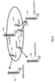
- Fig. 2 shows a table at the top and a network illustration at the bottom.
- the network illustration at the bottom of Fig. 2 shows a macro-cell 250, a femto-cell 260 which corresponds for example to an apartment A, another femto-cell 270 which corresponds, for example, to another apartment B, and another macro-cell 280.
- Within the macro-cell 250 there is a macro-UE 251 which is communicating with the corresponding MBS 259.
- the femto-cell 260 in which there is a femto-UE 261 communicating with the corresponding FBS 269.
- the femto-UE 261 transmits signals to the FBS 269
- interference for the macro-UE 251 is created at the base-station transceiver 259 which is indicated by the arrow 291, and to which the first row of the table at the top of Fig. 2 corresponds.
- the UE attached to the Home NodeB or the FBS 269 acts as aggressor, as creating interference to the victim, which corresponds in this scenario to the macro-nodeB in the uplink, i.e., to the MBS 259.
- the femto-cell 270 there is a femto-UE 271 communicating to a FBS 279.
- the macro-cell 280 in which a macro-UE 281 communicates with the MBS 289.
- the FBS 271 communicates with the femto-UE 271, it creates interference in the downlink for the macro-UE 281, which is indicated by the arrow 292 to which the second row of the table at the top of Fig. 2 corresponds.
- the Home NodeB i.e., the femto-base-station 279 is the aggressor creating an interference for the victim, in this case the MBS 289.
- the macro-UE 28 when transmitting to its MBS 289, creates interference at the FBS 279.
- the third row of the table corresponds to the scenario, in which the macro-UE 281 attached to the macro-nodeB or base-station transceiver 289 is the aggressor creating interference to the Home NodeB or FBS 279.
- the arrow 293 shows the interference that macro-UE 281 attached to the macro-nodeB 289 creates at the Home NodeB 279.
- the arrow 294 indicates interference which is created by a MBS 259 to a femto-UE 269 in the downlink.
- the fifth row of the table at the top of Fig.
- arrow 295 indicates the interference which is created by a femto-UE 271 to a FBS 269 in the uplink.
- the arrow 296 indicates interference which is created by a Home NodeB or FBS 279 to another FBS 269 in the downlink.
- 3GPP has prioritized two interference scenarios which are given by the arrows 291 and 293 in the corresponding rows in the table.
- the illustration of interference scenarios can also be found in the 3G Home NodeB Study Item in the technical report 3GPP TR 25.820, cf. "3G Home NodeB Study Item Technical Report", May 2008.
- Fig. 3 shows a MBS 310 which receives the signals of a macro-UE 312.
- the signals transmitted by the macro-UE 312 to the MBS 310 are indicated by the arrow 314.
- Fig. 3 shows a FBS 320 creating a femto-cell to which a femto-UE 322 is attached.
- Fig. 3 shows another FBS 330 to which a femto-UE 332 is attached.
- the femto-UE 332 transmits a signal to the FBS 330 which is indicated by the arrow 334.
- uplink transmission i.e., transmission from a UE to a base-station is considered.
- the macro-UE 312 transmits to MBS 310 using the same radio resources which femto-UE 332 uses to transmit the signals to the FBS 330.
- the macro-UE 312 creates an interference at the FBS 330 indicated by the arrow 316
- the femto-UE 332 creates an interference at the MBS 310 indicated by the arrow 336 respectively.
- the uplink radio resources are chosen in a manner that resources being reused in a femto-cell are spatially separated from MUEs using similar resources. Spatial separation as understood here as a radio distance, where radio distance refers to a certain attenuation. Generally, attenuation grows with a larger distance of transmitters, i.e., due to the so-called free space propagation loss.
- spatial separation evokes a higher attenuation and therewith corresponds to a large radio distance.
- this may also correspond to a large attenuation between the two radio devices, which may be evoked by e.g. walls or other obstacles on the radio paths.
- FIG. 4 shows a MBS 410 communicating with a macro-UE 412. Again, uplink communication is considered, i.e., the macro-UE 412 transmits a signal to the MBS 410 which is indicated by the arrow 414. Moreover, in the scenario there is a FBS 420 communicating with the femto-UE 422. The femto-UE 422 transmits a signal to the FBS indicated by the arrow 424. As opposed to the scenario depicted in Fig.
- macro-UE 412 using the same uplink resources as femto-UE 422 are not spatially separated, i.e., the attenuation between the macro-UE 412 and the FBS 420 is rather low. Therefore, the macro-UE 412 creates significant interference at the FBS 420 which is indicated by the arrow 416. In turn, the femto-UE 422 creates interference at the MBS 410 indicated by the arrow 426. In this scenario, the femto-cell-UE 222 is close to the macro-cell-UE 412 and therefore the attenuation in between is low. The drawbacks of the scenario are that high interference from the macro-UE 412 is created at the FBS 420.
- the femto-UE 422 requires high transmission power to achieve reasonable SIR at the FBS 420, which shortens battery life and is not green ITC. Moreover, a high femto-UE 422 interference is created at the MBS 410 due to the high femto-UE 422 transmission power. To maintain its SIR, the macro-UE 412 may have to further increase its transmission power, etc. From the consideration of benefits and drawbacks, which have been explained with the assistance of Figs. 3 and 4 , it follows that it is beneficial that FUEs reuse the resources of MUEs which are not close to their FBSs. This is once again illustrated in Fig. 5 .
- Fig. 5 shows a scenario with a MBS 510 communicating with a first macro-UE 512 and a second macro-UE 513. For better illustration purposes, the communication arrows are not depicted in Fig. 5 .
- a first FBS 520 communicating with a femto-UE 522
- a second FBS 530 communicating with a second femto-UE 532.
- the macro-UE 512 is spatially separated from the second femto-UE 532 and correspondingly uses the same resources, which is indicated by the arrow 514.
- Fig. 5 depicts an embodiment of beneficial resource assignment as the same resources are assigned to spatially separated entities.
- spatially separated means that the attenuation between such entities is high, in other words, the attenuation for example between the macro-UE 512 and the FBS 530, which is where the interference in the uplink is created, is high.
- the attenuation between the macro-UE 513 and the FBS 520 is high.
- Fig. 6 illustrates simulation results that show the benefits of spatial separation as described above.
- Fig. 6 illustrates SIR at a FBS versus relative femto-UE to macro-UE transmit power.
- the results depicted in Fig. 6 are determined for multiple scenarios, which are given in the legend of Fig. 6 , i.e. for indoor and outdoor scenarios for different spatial separations.
- the parameters varied are the spatial separation which translates to a higher attenuation, as explained above.
- indoor and outdoor scenarios are considered, where the indoor attenuation is higher than the outdoor attenuation.
- internal and external walls (buildings) are considered, which also model the respective attenuation.
- a wall in between two network entities may increase the attenuation and may correspond to a certain radio distance, which could equivalently by achieved by a spatial separation.
- SIR at the FBS mainly depends on three factors which are, first the relative femto-UE to macro-UE transmit power, second the distance between the macro-UE and the FBS, and third whether it is an indoor or an outdoor situation.
- the femto-UE could emit with high power and second, the spatial separation of a macro-UE and a femto-UE using the same resources could be utilized.
- the first solution in which the femto-UE emits with high power has two drawbacks. Firstly, an increase in the overall transmission power can be observed, which translates to a low battery life and non-green ITC. Moreover, the SIR of the MBS is decreased.
- Fig. 7 shows simulation results for the SIR at the MBS versus the relative femto-UE to macro-UE base-station distance. Again, simulations have been carried out for different parameters, wherein in Fig. 7 the transmission power of the femto-UE was varied according to the legend.
- the SIR at the MBS due to sixteen active FUEs assuming indoor MUEs of arbitrary precision in the cell is shown in Fig. 7 .
- a received power at the MBS equals that of a cell-edge MUE transmitting with full power. It can be noted that if FUEs transmit with - 30dBm then the SIR at the MBS is always sufficient. This is indicated in Fig.
- ICIC Inter-Cell Interference Coordination
- Embodiments may for example use the existing uplink ICIC messages of LTE.
- a resource block may comprise all kinds of radio resources in this context. According to the above description, a resource block may correspond to any predetermined radio resource from a resource pool.
- Another uplink ICIC message is for example the uplink interference overload indication which indicates the interference level experienced by a sending MBS on some resource blocks. This value may also be valid until reception of a new message carrying an update.
- Fig. 8 shows four MBSs 801, 802, 803 and 804. Furthermore, Fig. 8 illustrates a MUE 811 connected to MBS 801, a MUE 812 connected to MBS 802 and two MUEs 813 and 814 connected to the MBS 803. As two MUEs are connected to the MBS 803, interference coordination may be carried out in the uplink, i.e. the MBS 803 may send an HII to the neighboring MBSs 802 and 804. Therewith, the neighboring MBSs 802 and 804 may avoid reusing the radio resources indicated in the HII in their respective uplinks.
- a serving MBS may exchange uplink ICIC messages only with a neighboring MBSs. For example, for HII it is required that a cell-edge MUEs are detected so that an HII is sent to appropriate MBSs.
- RSRP Reference Signal Received Power
- a mobile communication system established by the MBSs and macro-cells may configure the MUEs to report certain reference signals measured with a certain reception power.
- the mobile communications system is aware of MUEs which are getting closer to FBSs, i.e. approach a FBS coverage area.
- a base-station transceiver 100 may comprise a communication unit 120 which is adapted for receiving the information through the radio interface from a mobile terminal in the mobile communication system, e.g. in terms of a measurement report.
- a report may include the identification of FBS for which the reference signal was measured, as well as an indication on the strength of the measured signal.
- the corresponding information on the identity which may be a FBS ID can be noted at the serving MBS.
- a MUE could try to connect to the FBS. If the nearby MUE is not allowed to connect to the femto-cell in its proximity, as is for example happens in the case of a closed-access femto-cells, as they are frequently used in homes, then at a serving MBS a new HII message may be prepared in one embodiment for the corresponding FBS based on the new information, and also on the valid existing HII information for this FBS, in case such information exists.
- a MBS may collect the reports from the MUEs, therewith detecting a FBS by another report, which informs the MBS that a connection to the FBS could not be established by a MUE, identifying said FBS. Then, the MBS may create a message for the FBS, informing it on the second portion 142 of radio resources, which it is supposed to use. Based on the received HII or any other message, the FBS may decide which resources to schedule to its FUEs. In embodiments, if possible, the FBS will avoid assigning resources assigned to MUEs in its proximity.
- the HII message as specified for LTE may be used.
- PRB Physical Resource Block
- a binary value is present, wherefore, value "1" indicates high interference sensitivity, and value "0" indicates low interference sensitivity, in embodiments this may be implemented vice versa.
- the messages may be directed directly to the corresponding FBS without broadcasting through the backhaul or backbone network, thus keeping the signalling effort at a reasonable level.
- the FBS for example, corresponding to a base-station transceiver 200 may receive its own cell-ID, corresponding to the information on an identity of the network node, which in this embodiment may be its own identity.
- the radio resource utilization may be determined and thus the base-station transceiver 200 can coordinate its own resources, i.e. the portion of the resources.
- the base-station transceiver 100 may comprise a communication unit 120 which is adapted for receiving another information on an identification and another information on an accessibility of a third base-station, the third base-station having a coverage area being surrounded by the coverage area 112 of the radio phase 110.
- the controller 130 may then be adapted for controlling the first portion 141 and the second portion 142 of radio resources and for determining a third portion of radio resources based on the pool 140 of radio sources, the other information on the identification and the other information on the accessibility.
- the base-station transceiver 100 may be adapted for coordinating the radio resources used by multiple FBSs within its coverage area.
- Fig. 9 shows a scenario, wherein a serving MBS 910 coordinates resource utilization for the uplink through HII messages.
- Fig. 9 shows three MBSs 910, 920 and 930.
- Fig. 9 shows three FBSs 940, 950 and 960.
- the arrows 970, 980, 985 and 990 illustrate HII messages, which are sent out by the serving MBS 910 in order to coordinate the uplink interference. Since these HII messages are dedicated, different resources can be utilized for the femto-cells 940, 950 and 960, as well as for the neighboring MBSs 920 and 930.
- HII may be used for neighbor MBSs of a the serving MBS. Embodiments may also use HII for femto-cells located within the serving MBSs.
- a communication unit 120 may be adapted for exploiting a multiplicity of measurement reports as for example for the RSRP of multiple UEs and therewith coordinate a multiplicity of femto-cells within its coverage.
- a similar mechanism may also be used for coordinating the downlink resources, i.e. a base-station transceiver 100 may utilize the first portion 141 for transmitting information to a mobile terminal.
- a base-station transceiver 200 i.e. a FBS may exploit existing RSRP measurements of FUEs which may be configured in the same manner as MUEs. The RSRP measurements or reports may then be used in embodiments to determine whether said FUE is in a cell-edge area.
- the controller 230 may be adapted for determining a measure on a radio or spatial distance between the base-station transceiver 200 and the other base-station transceiver 100, and the controller 230 may be adapted for controlling the portion 242 based on the radio or spatial distance.
- the radio distance may be due to a spatial distance or any attenuation between the FBS and a MUE, or vice-versa.
- a FBS or a base-station transceiver 200 may determine whether it is located near to a MBS or rather far away.
- the base-station transceiver 200 may operate means for receiving signals from the other base-station transceiver 100, e.g. in terms of reference signals, on the basis of which the attenuation, the radio or spatial distance can be determined.
- the means for receiving may correspond to a radio interface.
- the controller 230 may be adapted for determining whether it is located at a close range or at a far range based on the radio or spatial distance and for controlling the portion 242 of radio resources such that radio resources utilized by the other base-station transceiver 100 in the uplink and/or the downlink are avoided when the base-station transceiver 200 determined the far range.
- the base-station transceiver 200 may use uplink resources, which are not critical for the uplink of the MBS.
- the FBS should try to avoid reusing resources used between the MBS and such MUE in embodiments.
- the femto-cells may in one embodiment determine whether they are in a cell-edge area or in a cell-interior area.
- FBSs i.e. base-station transceiver 200
- RSRP measurements to establish the position in the macro-cell may thus very rarely be exploited, for example only at the power on or on a very coarse time basis.
- a base-station transceiver 200 or a FBS may react similar to a neighbor MBS in an embodiment. Generally, it may try to avoid scheduling its FUEs, for example, in the frequency range indicated by HII, i.e. it may try to minimize femto-cell to macro-cell uplink interference in this sensitive frequency range. In this embodiment, it is prevented that FUEs that are the same cell area, e.g. in the cell-edge or cell interior area, as MUEs use the same resource, and by this concept, FUEs and MUEs are inherently separated spatially or in terms of radio distance or attenuation, which share the same resources.
- femto-cells in cell-edge areas could also receive HII directed to the serving macro-cell assuming that they belong to the corresponding cell-edge area.
- the base station transceiver 200 may be adapted for overhearing or eavesdropping HII messages which are directed to neighboring MBSs. This may be carried out in the backbone network, e.g. by overhearing, eavesdropping or sniffing data packets, as e.g. TCP/IP data packets.
- the HII message may be constructed for determining the resource blocks, which are not marked as high interference blocks in any of the HII messages meant for neighboring MBSs. That is, a base-station transceiver 200 may comprise a controller 230, which is adapted for controlling the portion 242 of radio resources such that radio resources utilized by the base-station transceiver 100 in the uplink and/or in the downlink are reused when the base-station transceiver 200 determined the close range.
- the FBS can reuse resources used between the MBS and such MUE in embodiments, as they are not as critical as resources used for the far range.
- an FBS still tries to not reuse resource of a nearby MUE, in either uplink or downlink.
- the controller 230 can be adapted for controlling the portion 242 such that if the information on the identity is associated with a different base-station, the different base-station being different from the second base-station transceiver 100 as e.g. a neighbouring MBS, and further comprises an indication that it originated at the other base-station transceiver 100, the portion 242 is controlled such that mutual interference between the other base-station transceiver 100 using the radio resources according to the radio resource utilization and the base-station transceiver 200 utilizing the portion 242 of radio resources is reduced.
- resources used for interior MUEs of the serving cell may be marked as HII resource blocks for cell interior FBSs.
- Fig. 10 illustrates such an embodiment.
- Fig. 10 shows four MBSs 1010, 1011, 1012, and 1013, of which the base-station transceiver 1010 shall be considered the serving base-station.
- the serving base-station transceiver 1010 there is the cell interior area 1020 having cell interior FBSs as for example 1021 and 1022.
- the serving cell 1010 has three cell-edge areas 1031, 1032, and 1033, having for example a cell-edge FBS 1034, or a cell-edge MUE 1035.
- embodiments may subdivide a macro-cell in a multiplicity of cell areas, which may be located in a radial manner around a MBS.
- Fig. 11 illustrates how an HII message can be used to coordinate resources utilized by FBSs in the cell-edge part.
- Fig. 11 shows the serving base-station transceiver 1010 communicating an HII message to the neighbouring MBS 1011.
- the arrow 1060 indicating the HII message dedicated for the neighbouring MBS 1011 indicates that the FBSs may overhear said message.
- the HII message may be provided in a dedicated and/or individual manner.
- an HII message is sent from the serving MBS 1010 to the neighbouring MBS 1011 and to the FBSs 1051, 1052, 1053 and 1054 in the cell-edge area 1031.
- the same HII message from the neighbouring MBS 1011 may be sent to the serving MBS 1010 and to FBSs in the cell-edge area of the MBS 1011.
- the FBSs in the cell-edge area of the MBS 1011 may decide, based on the received HIIs, how to assign resources to their FUEs.
- an uplink interference overload indication signalling may be utilized in embodiments for interference coordination with femto-cells.
- This message is also part of the LTE specifications and may also be sent to all femto-cells. Then, the femto-cells using the highly interfered resource blocks of MUEs may stop using them and chose the others in embodiments. Alternatively, femto-cells may reduce their transmission power in embodiments over these resource blocks.
- the cell interior area could also be split in a cell center and a cell area between the cell center and cell-edge.
- a macro-cell may be subdivided into multiple different areas which could for example be determined by the RSRP measurements.
- the cell center area could be recognized by RSRP measurements of FUEs, for example detecting strong signals from the MBSs in which they are geographically situated.
- a more targeted resource assignment with the cell areas split as illustrated in Figs. 10 and 11 may also be carried out, principally using a multiplicity of different cell areas.
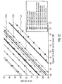
- Fig. 12 shows simulation results of the embodiments in terms of a view graph illustrating SIR at the FBS versus relative FUE to MUE transmission power.
- Fig. 12 illustrates a similar view graph as Fig. 6 .
- the improvements of the average SIR due to embodiments are illustrated.
- Embodiments may force spatial separation of the macro and the femto entities that use the same frequencies or radio resources, and therewith significantly improve the average SIR for a given relative FUE to MUE transmit power.
- Fig. 12 illustrates the average SIR at a FBS for the conventional method, i.e. if no resource coordination is carried out which is indicated by arrow 1201 in Fig. 12 .
- Fig. 12 shows simulation results of the embodiments in terms of a view graph illustrating SIR at the FBS versus relative FUE to MUE transmission power.
- Fig. 12 illustrates a similar view graph as Fig. 6 .
- the improvements of the average SIR due to embodiments are illustrated.
- FIG. 12 shows, by the arrow 1202, the average SIR at a FBS for a conventional method when no coordination is carried out but the most critical femto-cells are switched off.
- arrow 1203 shows the average SIR at the FBS for an embodiment, where a coordination between femto and macro resources is carried out according to the above-described embodiments. The SIR improvements are significant.
- Embodiments were regarded mainly in the light of uplink transmission and therewith in the light of uplink interference coordination.
- Embodiments may also carry out downlink interference coordination.
- Embodiments may follow the similar line of reasoning as for uplink transmission.
- a FBS reuses the resources of a MBS which are intended for MUEs far away from the specific FBS.
- Existing downlink ICIC messages in e.g. LTE indicate for each PRB if the transmission power is above a threshold value or not. This information may not be sufficient for femto-to-macro cell downlink interference coordination.
- embodiments may introduce a new message for the downlink interference coordination between femto and macro cells.
- LTE serving MBSs exchange downlink ICIC messages only with neighboring MBSs.
- the MUE may establish or attach accordingly if they are in close proximity of a femto cell. This may for example in embodiments be done by carrying out measurements of RSRPs by MUEs in the same manner as done to establish if MUEs are in a cell-edge area.
- the FBS identifications may be noted by the MBS.
- a new message may be prepared for the corresponding FBS.
- the new message may be based on new information and/or on still existing information for this FBS, if any such information exists.
- the base-station transceiver 200 i.e. the FBS may decide which resources to schedule for its downlink transmission for FUEs. If possible, it may avoid assigning resources which the corresponding MBS assigned for transmission to MUEs in the proximity of this FBS.
- the downlink message may contain a target femto-cell ID and a string in which each position represents a PRB, for which a value of, for example, "1" indicates a high interference sensitivity and a value of, for example, "0" indicates a low interference sensitivity, and vice versa respectively.
- Embodiments provide the advantage that a femto cell may share resources with macro cells more efficiently enhancing the coverage of LTE and/or LTE-A in the home environment.
- Embodiments may enable interference coordination in femto cell deployment and enable efficient interference mitigation techniques.
- Embodiments may reuse existing LTE / LTE-A intercell interference coordination methods and signalling to coordinate interference between femto and macro cells.
- Embodiments may therewith provide the advantage that they have only minimal impact on the existing LTE standard. By lowering the mutual interference and the overall transmission power, the system capacity may be significantly enhanced by the embodiments of the present invention.
- the inventive methods can be implemented in hardware or in software.
- the implementation can be performed using a digital storage medium, in particular a disc, a DVD or a CD having electronically readable control signals stored thereon which cooperate with a programmable computer system such that the inventive methods are performed.
- the present invention is, therefore, a computer program product with a program code stored on a machine readable carrier, the program code being operative for performing the inventive methods when the computer program product runs on a computer.
- the inventive methods are, therefore, a computer program having a program code for performing at least one of the inventive methods when the computer program runs on a computer.
Priority Applications (3)
| Application Number | Priority Date | Filing Date | Title |
|---|---|---|---|
| DE200860001803 DE602008001803D1 (de) | 2008-10-24 | 2008-10-24 | Koordination der Funkressourcenzuteilung in einem Makro-/Mikrozellen-Funkkommunikationssystem |
| EP20080018665 EP2180739B1 (fr) | 2008-10-24 | 2008-10-24 | Coordination d'allocation de resources radio dans dans un système radio macro-/microcellulaire |
| JP2009245215A JP4923093B2 (ja) | 2008-10-24 | 2009-10-26 | 基地局トランシーバ |
Applications Claiming Priority (1)
| Application Number | Priority Date | Filing Date | Title |
|---|---|---|---|
| EP20080018665 EP2180739B1 (fr) | 2008-10-24 | 2008-10-24 | Coordination d'allocation de resources radio dans dans un système radio macro-/microcellulaire |
Publications (2)
| Publication Number | Publication Date |
|---|---|
| EP2180739A1 true EP2180739A1 (fr) | 2010-04-28 |
| EP2180739B1 EP2180739B1 (fr) | 2010-07-14 |
Family
ID=40474817
Family Applications (1)
| Application Number | Title | Priority Date | Filing Date |
|---|---|---|---|
| EP20080018665 Expired - Fee Related EP2180739B1 (fr) | 2008-10-24 | 2008-10-24 | Coordination d'allocation de resources radio dans dans un système radio macro-/microcellulaire |
Country Status (3)
| Country | Link |
|---|---|
| EP (1) | EP2180739B1 (fr) |
| JP (1) | JP4923093B2 (fr) |
| DE (1) | DE602008001803D1 (fr) |
Cited By (16)
| Publication number | Priority date | Publication date | Assignee | Title |
|---|---|---|---|---|
| WO2012079757A1 (fr) | 2010-12-15 | 2012-06-21 | Telefonaktiebolaget L M Ericsson (Publ) | Technique de coordination de brouillage entre cellules dans un réseau de communication hétérogène |
| EP2538741A1 (fr) * | 2011-06-22 | 2012-12-26 | NTT DoCoMo, Inc. | Coordination des interférences entre des stations de base |
| FR2986687A1 (fr) * | 2012-02-08 | 2013-08-09 | Commissariat Energie Atomique | Gestion dynamique de petites cellules pour optimiser la consommation energetique d'un reseau |
| US20130324136A1 (en) * | 2011-02-17 | 2013-12-05 | Sharp Kabushiki Kaisha | Communication system, base station apparatuses, and terminal devices |
| CN103597895A (zh) * | 2011-06-10 | 2014-02-19 | 瑞典爱立信有限公司 | 针对小区基站的动态载波选择 |
| US20140295872A1 (en) * | 2013-03-29 | 2014-10-02 | Intellectual Discovery Co., Ltd. | SYSTEM AND METHOD TO ALLOCATE FREQUENCY DYNAMICALLY BASED ON PRIORITY OF QUALITY OF EXPERIENCE (QoE) IN 3GPP LTE HETEROGENEOUS NETWORK |
| WO2014186124A1 (fr) * | 2013-05-16 | 2014-11-20 | Alcatel Lucent | Procédés et systèmes d'ordonnancement de communication dans un réseau à canal commun |
| US9014707B2 (en) | 2011-02-22 | 2015-04-21 | Samsung Electronics Co., Ltd. | Apparatus and method for hierarchical rate splitting in hierarchical cell communication system |
| US9094848B2 (en) | 2010-08-23 | 2015-07-28 | Panasonic Intellectual Property Corporation Of America | Base station apparatus and transmission control method |
| EP2824955A4 (fr) * | 2012-03-05 | 2016-01-27 | Sony Corp | Dispositif de commande de communication, procédé de commande de communication et station de base |
| WO2016022912A1 (fr) * | 2014-08-08 | 2016-02-11 | Sprint Spectrum Lp | Systèmes et procédés de planification d'une communication au niveau d'un nœud d'accès |
| US9332510B2 (en) | 2010-08-17 | 2016-05-03 | Qualcomm Incorporated | Apparatus and method for controlling inter-cell interference between femtocells and macrocells |
| US9572064B2 (en) | 2014-08-08 | 2017-02-14 | Sprint Spectrum L.P. | Systems and methods for scheduling transmissions from an access node |
| US9608794B2 (en) | 2014-08-08 | 2017-03-28 | Sprint Spectrum L.P. | Systems and methods for scheduling transmissions between an access node and wireless devices |
| US9706473B2 (en) | 2010-06-29 | 2017-07-11 | Qualcomm Incorporated | Method and apparatus for mitigating interference in femtocell deployments |
| US9730191B2 (en) | 2010-12-02 | 2017-08-08 | Fujitsu Limited | Wireless communication system, base station, mobile station and wireless communication method |
Families Citing this family (4)
| Publication number | Priority date | Publication date | Assignee | Title |
|---|---|---|---|---|
| JP2013005248A (ja) * | 2011-06-17 | 2013-01-07 | Sharp Corp | 集中制御局装置、制御局装置、端末装置、通信システム及び通信方法 |
| US10212701B2 (en) | 2013-04-10 | 2019-02-19 | Nec Corporation | Wireless communication system, base station and wireless communication method |
| US20150264552A1 (en) * | 2014-03-14 | 2015-09-17 | Gang Xiong | Systems, methods, and devices for device-to-device discovery and communication |
| JP6308328B2 (ja) * | 2014-09-23 | 2018-04-11 | 富士通株式会社 | アンライセンスバンドにおける通信方法、装置及びシステム |
Citations (2)
| Publication number | Priority date | Publication date | Assignee | Title |
|---|---|---|---|---|
| US5920819A (en) | 1996-03-01 | 1999-07-06 | Kabushiki Kaisha Toshiba | Overlay cell type mobile communication system |
| GB2446196A (en) | 2007-02-02 | 2008-08-06 | Ubiquisys Ltd | Basestation measurement modes |
Family Cites Families (3)
| Publication number | Priority date | Publication date | Assignee | Title |
|---|---|---|---|---|
| JP2937995B1 (ja) * | 1998-03-06 | 1999-08-23 | 株式会社ワイ・アール・ピー移動通信基盤技術研究所 | チャネル割当て方法および移動通信網 |
| JP4708162B2 (ja) * | 2005-11-02 | 2011-06-22 | Kddi株式会社 | 無線通信システム及び無線通信制御方法 |
| EP2130400B1 (fr) * | 2007-03-30 | 2016-03-09 | Telefonaktiebolaget LM Ericsson (publ) | Procédé et dispositif pour l'utilisation de fréquence dynamique dans un réseau cellulaire |
-
2008
- 2008-10-24 DE DE200860001803 patent/DE602008001803D1/de active Active
- 2008-10-24 EP EP20080018665 patent/EP2180739B1/fr not_active Expired - Fee Related
-
2009
- 2009-10-26 JP JP2009245215A patent/JP4923093B2/ja not_active Expired - Fee Related
Patent Citations (2)
| Publication number | Priority date | Publication date | Assignee | Title |
|---|---|---|---|---|
| US5920819A (en) | 1996-03-01 | 1999-07-06 | Kabushiki Kaisha Toshiba | Overlay cell type mobile communication system |
| GB2446196A (en) | 2007-02-02 | 2008-08-06 | Ubiquisys Ltd | Basestation measurement modes |
Non-Patent Citations (3)
| Title |
|---|
| 3RD GENERATION PARTNERSHIP PROJECT; TECHNICAL SPECIFICATION GROUP RADIO ACCESS NETWORK (E-UTRAN): "X2 general aspects and principles (Release 8)", 3GPP TS 36.420 V8.0.0 (2007-12), 1 December 2007 (2007-12-01), XP002522290 * |
| MOTOROLA: "Text proposal for TR3.020", 3GPP DRAFT; R3-071981, 3RD GENERATION PARTNERSHIP PROJECT (3GPP), MOBILE COMPETENCE CENTRE ; 650, ROUTE DES LUCIOLES ; F-06921 SOPHIA-ANTIPOLIS CEDEX ; FRANCE, vol. tsg_ran\WG3_Iu\TSGR3_57bis\docs, no. Sophia Antipolis, France; 20071008, 10 October 2007 (2007-10-10), XP050162762 * |
| NORTEL: "Macro-Home eNB neighboring Paradigm", 3GPP DRAFT; R3-071577_MACRO-HOME ENB NEIGHBORING PARADIGM_13.2.5C_HNBNEIGH.REV0, 3RD GENERATION PARTNERSHIP PROJECT (3GPP), MOBILE COMPETENCE CENTRE ; 650, ROUTE DES LUCIOLES ; F-06921 SOPHIA-ANTIPOLIS CEDEX ; FRANCE, vol. tsg_ran\WG3_Iu\TSGR3_57\docs, no. Athens, Greece; 20070820, 15 August 2007 (2007-08-15), XP050162392 * |
Cited By (30)
| Publication number | Priority date | Publication date | Assignee | Title |
|---|---|---|---|---|
| US9706473B2 (en) | 2010-06-29 | 2017-07-11 | Qualcomm Incorporated | Method and apparatus for mitigating interference in femtocell deployments |
| US9332510B2 (en) | 2010-08-17 | 2016-05-03 | Qualcomm Incorporated | Apparatus and method for controlling inter-cell interference between femtocells and macrocells |
| US9094848B2 (en) | 2010-08-23 | 2015-07-28 | Panasonic Intellectual Property Corporation Of America | Base station apparatus and transmission control method |
| US9730191B2 (en) | 2010-12-02 | 2017-08-08 | Fujitsu Limited | Wireless communication system, base station, mobile station and wireless communication method |
| US8559961B2 (en) | 2010-12-15 | 2013-10-15 | Telefonaktiebolaget L M Ericsson (Publ) | Fractional frequency reuse in heterogeneous networks |
| WO2012080800A1 (fr) * | 2010-12-15 | 2012-06-21 | Telefonaktiebolaget Lm Ericsson (Publ) | Réutilisation de fréquences fractionnaires dans des réseaux hétérogènes |
| WO2012079604A1 (fr) * | 2010-12-15 | 2012-06-21 | Telefonaktiebolaget L M Ericsson (Publ) | Technique de coordination de brouillage entre cellules dans un réseau de communication hétérogène |
| WO2012079757A1 (fr) | 2010-12-15 | 2012-06-21 | Telefonaktiebolaget L M Ericsson (Publ) | Technique de coordination de brouillage entre cellules dans un réseau de communication hétérogène |
| US20130310060A1 (en) * | 2010-12-15 | 2013-11-21 | Telefonaktiebolaget L M Ericsson (Publ) | Fractional frequency reuse in heterogeneous networks |
| US9319167B2 (en) | 2010-12-15 | 2016-04-19 | Telefonaktiebolaget Lm Ericsson (Publ) | Technique for inter-cell interference coordination in a heterogeneous communication network |
| US10097300B2 (en) | 2010-12-15 | 2018-10-09 | Telefonaktiebolaget Lm Ericsson (Publ) | Fractional frequency reuse in heterogeneous networks |
| US20130324136A1 (en) * | 2011-02-17 | 2013-12-05 | Sharp Kabushiki Kaisha | Communication system, base station apparatuses, and terminal devices |
| US9014707B2 (en) | 2011-02-22 | 2015-04-21 | Samsung Electronics Co., Ltd. | Apparatus and method for hierarchical rate splitting in hierarchical cell communication system |
| CN103597895B (zh) * | 2011-06-10 | 2018-05-01 | 瑞典爱立信有限公司 | 针对小区基站的动态载波选择 |
| CN103597895A (zh) * | 2011-06-10 | 2014-02-19 | 瑞典爱立信有限公司 | 针对小区基站的动态载波选择 |
| WO2012175496A1 (fr) * | 2011-06-22 | 2012-12-27 | Ntt Docomo, Inc. | Coordination d'interférences entre stations de base |
| EP2538741A1 (fr) * | 2011-06-22 | 2012-12-26 | NTT DoCoMo, Inc. | Coordination des interférences entre des stations de base |
| FR2986687A1 (fr) * | 2012-02-08 | 2013-08-09 | Commissariat Energie Atomique | Gestion dynamique de petites cellules pour optimiser la consommation energetique d'un reseau |
| US9319892B2 (en) | 2012-02-08 | 2016-04-19 | Commissariat A L'energie Atomique Et Aux Energies Alternatives | Dynamic management of small cells for optimizing the energy consumption of a network |
| EP2627111A1 (fr) * | 2012-02-08 | 2013-08-14 | Commissariat A L'energie Atomique Et Aux Energies Alternatives | Gestion dynamique de petites cellules pour optimiser la consommation énergétique d'un réseau |
| EP2824955A4 (fr) * | 2012-03-05 | 2016-01-27 | Sony Corp | Dispositif de commande de communication, procédé de commande de communication et station de base |
| US9794948B2 (en) | 2012-03-05 | 2017-10-17 | Sony Corporation | Communication control device, communication control method, and base station |
| US9374830B2 (en) | 2012-03-05 | 2016-06-21 | Sony Corporation | Communication control device, communication control method, and base station |
| US9313793B2 (en) * | 2013-03-29 | 2016-04-12 | Intellectual Discovery Co., Ltd. | System and method to allocate frequency dynamically based on priority of quality of experience (QoE) in 3GPP LTE heterogeneous network |
| US20140295872A1 (en) * | 2013-03-29 | 2014-10-02 | Intellectual Discovery Co., Ltd. | SYSTEM AND METHOD TO ALLOCATE FREQUENCY DYNAMICALLY BASED ON PRIORITY OF QUALITY OF EXPERIENCE (QoE) IN 3GPP LTE HETEROGENEOUS NETWORK |
| US9370020B2 (en) | 2013-05-16 | 2016-06-14 | Alcatel Lucent | Methods and systems for scheduling communications in a co-channel network |
| WO2014186124A1 (fr) * | 2013-05-16 | 2014-11-20 | Alcatel Lucent | Procédés et systèmes d'ordonnancement de communication dans un réseau à canal commun |
| US9608794B2 (en) | 2014-08-08 | 2017-03-28 | Sprint Spectrum L.P. | Systems and methods for scheduling transmissions between an access node and wireless devices |
| US9572064B2 (en) | 2014-08-08 | 2017-02-14 | Sprint Spectrum L.P. | Systems and methods for scheduling transmissions from an access node |
| WO2016022912A1 (fr) * | 2014-08-08 | 2016-02-11 | Sprint Spectrum Lp | Systèmes et procédés de planification d'une communication au niveau d'un nœud d'accès |
Also Published As
| Publication number | Publication date |
|---|---|
| EP2180739B1 (fr) | 2010-07-14 |
| JP4923093B2 (ja) | 2012-04-25 |
| DE602008001803D1 (de) | 2010-08-26 |
| JP2010124462A (ja) | 2010-06-03 |
Similar Documents
| Publication | Publication Date | Title |
|---|---|---|
| EP2180739B1 (fr) | Coordination d'allocation de resources radio dans dans un système radio macro-/microcellulaire | |
| CN107318125B (zh) | 用于配置abs传输模式以及对应测量模式的方法和网络节点 | |
| US10321465B2 (en) | Mobile communication system and mobile communication method | |
| US9281932B2 (en) | Methods and apparatus for subframe interlacing in heterogeneous networks | |
| EP2928235B1 (fr) | Procédés pour faire fonctionner une première station de base et une seconde station de base dans un système de communication radio, une première station de base et la seconde station de base correspondante | |
| KR101876884B1 (ko) | 전기통신시스템에서 채널 상태 정보를 보고하기 위한 방법 및 배열 | |
| KR101510090B1 (ko) | 셀룰러 통신 네트워크에서 셀간 간섭 조정을 위한 방법, 셀룰러 통신 네트워크의 네트워크 구성요소, 및 셀룰러 통신 네트워크 | |
| KR101636663B1 (ko) | 소형 기지국들 또는 ue 디바이스들에 의한 파일롯 신호들의 송신을 위한 자원들의 할당을 위한 방법들 및 장치 | |
| JP2013504984A5 (fr) | ||
| EP2384595B1 (fr) | Régulation de puissance dans un système de communication cellulaire multicouche | |
| US20120082047A1 (en) | User equipment measurement for interference management in heterogeneous networks with femto cells | |
| EP2975898A1 (fr) | Système et procédé pour une coordination de brouillage entre des noeuds de communication | |
| US20230269611A1 (en) | Cross link interference measurement configuration | |
| CN110662253B (zh) | 用于载波分配的方法和设备 | |
| WO2014185695A1 (fr) | Procédé et appareil permettant l'allocation d'identifiants de cellules physiques dans un système de communication sans fil | |
| JP2011097372A (ja) | 大セル基地局及び通信制御方法 | |
| US20230164610A1 (en) | Cross link interference (cli) measurement adaptation | |
| EP2490497A1 (fr) | Émetteur-récepteur de station mobile et de base, procédés et programmes informations pour la fourniture d'une configuration de mesure et d'un résultat de mesure | |
| Chhetri et al. | Intercell Interference Mitigation in LTE-Advanced Heterogeneous Network | |
| JP5366907B2 (ja) | 大セル基地局及び通信制御方法 | |
| Khwandah et al. | Interference management in LTE co-channel femtocells | |
| RU2575702C2 (ru) | Способы и сетевые узлы для конфигурации шаблонов передачи почти пустого подкадра и соответствующих шаблонов измерений для снижения помех между сотами в гетерогенной системе сотовой радиосвязи | |
| Hussain | Interference Alignment in Heterogeneous Cellular Networks | |
| KR20130026361A (ko) | 이기종 망간에 ec의 pdsch 시작심볼 결정 방법 및 그를 위한 이동통신 시스템 |
Legal Events
| Date | Code | Title | Description |
|---|---|---|---|
| GRAP | Despatch of communication of intention to grant a patent |
Free format text: ORIGINAL CODE: EPIDOSNIGR1 |
|
| PUAI | Public reference made under article 153(3) epc to a published international application that has entered the european phase |
Free format text: ORIGINAL CODE: 0009012 |
|
| 17P | Request for examination filed |
Effective date: 20091007 |
|
| AK | Designated contracting states |
Kind code of ref document: A1 Designated state(s): AT BE BG CH CY CZ DE DK EE ES FI FR GB GR HR HU IE IS IT LI LT LU LV MC MT NL NO PL PT RO SE SI SK TR |
|
| AX | Request for extension of the european patent |
Extension state: AL BA MK RS |
|
| GRAS | Grant fee paid |
Free format text: ORIGINAL CODE: EPIDOSNIGR3 |
|
| GRAA | (expected) grant |
Free format text: ORIGINAL CODE: 0009210 |
|
| AK | Designated contracting states |
Kind code of ref document: B1 Designated state(s): DE GB |
|
| REG | Reference to a national code |
Ref country code: GB Ref legal event code: FG4D |
|
| REF | Corresponds to: |
Ref document number: 602008001803 Country of ref document: DE Date of ref document: 20100826 Kind code of ref document: P |
|
| AKX | Designation fees paid |
Designated state(s): DE GB |
|
| PLBE | No opposition filed within time limit |
Free format text: ORIGINAL CODE: 0009261 |
|
| STAA | Information on the status of an ep patent application or granted ep patent |
Free format text: STATUS: NO OPPOSITION FILED WITHIN TIME LIMIT |
|
| 26N | No opposition filed |
Effective date: 20110415 |
|
| REG | Reference to a national code |
Ref country code: DE Ref legal event code: R097 Ref document number: 602008001803 Country of ref document: DE Effective date: 20110415 |
|
| PGFP | Annual fee paid to national office [announced via postgrant information from national office to epo] |
Ref country code: GB Payment date: 20131023 Year of fee payment: 6 Ref country code: DE Payment date: 20131016 Year of fee payment: 6 |
|
| REG | Reference to a national code |
Ref country code: DE Ref legal event code: R119 Ref document number: 602008001803 Country of ref document: DE |
|
| GBPC | Gb: european patent ceased through non-payment of renewal fee |
Effective date: 20141024 |
|
| PG25 | Lapsed in a contracting state [announced via postgrant information from national office to epo] |
Ref country code: GB Free format text: LAPSE BECAUSE OF NON-PAYMENT OF DUE FEES Effective date: 20141024 Ref country code: DE Free format text: LAPSE BECAUSE OF NON-PAYMENT OF DUE FEES Effective date: 20150501 |