EP2180668B1 - Gehäuseanwendung für tragbare elektronische Vorrichtung - Google Patents
Gehäuseanwendung für tragbare elektronische Vorrichtung Download PDFInfo
- Publication number
- EP2180668B1 EP2180668B1 EP09174028A EP09174028A EP2180668B1 EP 2180668 B1 EP2180668 B1 EP 2180668B1 EP 09174028 A EP09174028 A EP 09174028A EP 09174028 A EP09174028 A EP 09174028A EP 2180668 B1 EP2180668 B1 EP 2180668B1
- Authority
- EP
- European Patent Office
- Prior art keywords
- engaging
- housing
- guiding
- force receiving
- engaging member
- Prior art date
- Legal status (The legal status is an assumption and is not a legal conclusion. Google has not performed a legal analysis and makes no representation as to the accuracy of the status listed.)
- Active
Links
Images


Classifications
-
- H—ELECTRICITY
- H04—ELECTRIC COMMUNICATION TECHNIQUE
- H04M—TELEPHONIC COMMUNICATION
- H04M1/00—Substation equipment, e.g. for use by subscribers
- H04M1/02—Constructional features of telephone sets
- H04M1/0202—Portable telephone sets, e.g. cordless phones, mobile phones or bar type handsets
- H04M1/0249—Details of the mechanical connection between the housing parts or relating to the method of assembly
- H04M1/0252—Details of the mechanical connection between the housing parts or relating to the method of assembly by means of a snap-on mechanism
-
- H—ELECTRICITY
- H04—ELECTRIC COMMUNICATION TECHNIQUE
- H04M—TELEPHONIC COMMUNICATION
- H04M1/00—Substation equipment, e.g. for use by subscribers
- H04M1/02—Constructional features of telephone sets
- H04M1/0202—Portable telephone sets, e.g. cordless phones, mobile phones or bar type handsets
- H04M1/0249—Details of the mechanical connection between the housing parts or relating to the method of assembly
-
- Y—GENERAL TAGGING OF NEW TECHNOLOGICAL DEVELOPMENTS; GENERAL TAGGING OF CROSS-SECTIONAL TECHNOLOGIES SPANNING OVER SEVERAL SECTIONS OF THE IPC; TECHNICAL SUBJECTS COVERED BY FORMER USPC CROSS-REFERENCE ART COLLECTIONS [XRACs] AND DIGESTS
- Y02—TECHNOLOGIES OR APPLICATIONS FOR MITIGATION OR ADAPTATION AGAINST CLIMATE CHANGE
- Y02P—CLIMATE CHANGE MITIGATION TECHNOLOGIES IN THE PRODUCTION OR PROCESSING OF GOODS
- Y02P20/00—Technologies relating to chemical industry
- Y02P20/141—Feedstock
Definitions
- the present invention relates to a housing assembly, and more particularly, to a housing assembly for a portable electronic device.
- housing assembly for an electrical device depends on screws to connect the housing assembly together and the quality of assembly for the electrical device, such as the connection between the parts of the housing assembly depends on the proper installation of the screws.
- U.S. Patent No. 5,946,395 to Petrella et al. discloses a "Housing assembly for an electronic device"
- U.S. Patent No. 7,116,780 to Sun discloses a "Housing assembly for a portable electronic device”
- U.S. Patent No. 7,149,306 to Pan discloses a "Housing assembly of portable electronic device" all of the prior art are hereby disclosed for reference.
- the housing assembly disclosed by Petrella et al. includes a first housing having multiple hooks on a side thereof and a second housing with multiple hook acceptors on a side thereof, the hooks are engaged with the hook acceptors.
- Multiple tabs and a slidable element are located between the first and second housings.
- the slidable element includes multiple notches so as to be engaged with protrusions on the first and second housings to connect the first and second housings together.
- the housing assembly disclosed by Sun includes multiple parts and each part includes multiple protrusions and a U-shaped slidable element so as to connect the multiple parts together.
- the slidable elements include multiple protrusions which are engaged with the protrusions on the parts. However, when disengaging these protrusions, the parts are separated so that this type of assembly is not suitable for the housing assembly that allows the user to replace a single part.
- the housing assembly by Pan discloses a similar structure as that of Sun.
- U.S. Patent Application No. 2004/0203518 to Zheng et al. discloses an "Enclosure assembly for portable electronic device"
- U.S. Patent Application No. 2005/037717 to Oin et al. discloses a "Latching assembly for a removable cover of a wireless communication device”
- U.S. Patent No. 5,469,982 to Gordecki et al. discloses a "Four-sided housing latch”
- U.S. Patent Application No. 2003/219117 to Sun discloses a "Device for fastening body of cellular phone or PDA to its base", all of the prior art are hereby disclosed for reference.
- the enclosure assembly disclosed by Zheng et al. includes a cover, a plurality of latching elements and a housing.
- the cover has a plurality of hooks at a lower end and a plurality of tabs defining grooves therein extending from sidewalls thereof.
- Each latching element comprises a plurality of protrusions and a detaching means.
- the housing has a plurality of slots at its sides and projections at its lower end.
- the wireless communication device disclosed by Oin et al. includes a removable panel, a base cover and a latching assembly.
- the removable panel has a first mounting portion.
- the base cover has a second mounting portion corresponding to the first mounting portion of the removable panel.
- the housing latch disclosed by Gordecki et al. is a resilient latch attached to a pair of interlocked housings having a recessed border and mating cavities in the recessed border. Placed around the border of the paired housings, the latch having protrusions engages with the cavities of the paired housings, as the latch is slid around the border.
- the body includes a lower peripheral flange
- the base includes an upper peripheral flange
- the arrangement is shaped like a closed loop with a substantially T-shaped cross-section.
- the arrangement comprises an upper peripheral groove and a lower peripheral groove wherein the lower peripheral flange is aligned with the upper peripheral groove and the upper peripheral flange is aligned with the lower peripheral groove respectively prior to threadedly securing the base, the arrangement, and the body together.
- the present invention intends to provide a housing assembly for a portable electronic device and the housing assembly can be quickly assembled and manufactured at low cost, the users can conveniently replace the housings of the housing assembly.
- the present invention relates to a housing assembly for a portable electronic device and comprises a mounting assembly having a first part and a second part which is connected to the first part.
- the combination of the first and second parts defines a slot and multiple accommodating rooms, and each accommodating room has an opening.
- Multiple engaging assemblies each have a first elastic member and a first engaging member received in the accommodating room of the mounting assembly.
- the first engaging member includes a first force receiving portion and a first engaging portion located corresponding to the opening of the accommodating room.
- a first housing is connected to the mounting assembly and includes multiple assembling portions and each assembling portion is located corresponding to the first engaging portion of the first engaging member.
- Multiple guiding members each have a first guiding portion corresponding to the first force receiving portion of the first engaging member.
- a connection member is connected with the guiding members and includes a release portion which is located corresponding to the slot of the mounting assembly.
- the first engaging portion of the first engaging member is engaged with the assembling portion of the first housing by a force of the first elastic member.
- the first force receiving portion of the first engaging member is moved to a position, and the first engaging member is disengaged from the assembling portion of the first housing.
- the first and second parts define multiple side rooms and a path, wherein the multiple side rooms are located corresponding to the accommodating rooms and the path is located corresponding to the side rooms.
- the guiding members are installed in the side rooms and the connection member is installed in the path.
- the first part includes a board and multiple lugs extend from the board.
- the second part includes multiple reception holes with which the lugs are engaged.
- each engaging assembly further comprises a second engaging member mounted in the accommodating room of the mounting assembly.
- the second engaging member includes a second force receiving portion and a second engaging portion located corresponding to the opening of the accommodating room.
- a second elastic member is located between the accommodating room and the second engaging member.
- the guiding member includes a second guiding portion which is located corresponding to the second force receiving portion of the second engaging member.
- a second housing is connected to the second part of the mounting assembly and includes multiple connection portions. Each connection portion is located corresponding to the second engaging portion of the second engaging member.
- connection portion of the second housing includes an engaging hole and the second engaging portion of the second engaging member includes a second engaging inclined surface which guides the connection portion of the second housing to be connected with the second engaging portion of the second engaging member.
- the first force receiving portion of the first engaging member has a first force receiving inclined surface and the first guiding portion of the guiding member has a first guiding inclined surface which is slidably engaged with the first force receiving inclined surface to move the first engaging member relative to the guiding member.
- the second force receiving portion of the second engaging member has a second force receiving inclined surface and the second guiding portion of the guiding member has a second guiding inclined surface which is slidably engaged with the second force receiving inclined surface to move the second engaging member relative to the guiding member.
- the assembling portion of the first housing has an engaging hole and the first engaging portion of the first engaging member has a first engaging inclined surface which is located corresponding to the assembling portion of the first housing so as to guide the assembling portion of the first housing to be connected with the first engaging portion of the first engaging member.
- a third elastic member is located between the first part and the first housing.
- a fourth elastic member is located between the second part and the second housing.
- the first and second engaging members include first and second guiding slots and first and second force receiving portions respectively.
- a guiding member is movably connected to the connection member and includes a first cam and a second cam, wherein the first cam is located corresponding to the first force receiving portion of the first engaging member and the second cam is located corresponding to the second force receiving portion of the second engaging member.
- the first and second cams include first and second shafts which respectively extend through the first and second guiding slots of the first and second engaging members and are pivotally connected to the mounting assembly.
- the release portion includes a pivoted end and an operation end opposite to the pivoted end.
- the release portion includes a first portion and a second portion
- a sliding member is connected to the connection member and includes a first inclined surface which is located corresponding to the first portion and a second inclined portion which is located corresponding to the second portion.
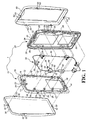
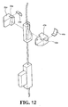
- a housing assembly according to a first embodiment of the present invention comprises a mounting assembly 1, multiple engaging assemblies 30, a first housing 50, a second housing 60, multiple guiding members 70, and a connection member 80.
- the mounting assembly 1 has a first part 10 and a second part 20 which is connected to the first part 10.
- the first part 10 includes a first wall 11, a second wall 12 located corresponding to the first wall 11, a third wall 13 connected between the first and second walls 11, 12, and a fourth wall 14 located corresponding to the third wall 13 and connected between the first and second walls 1 l, 12.
- the first and second walls 11, 12 are located on two sides of the first part 10 and the third and fourth walls 13, 14 are located on two ends of the first part 10.
- a board 16 is connected with the first, second, third and fourth walls 11, 12, 13, 14, and multiple lugs 18 extend from the board 16.
- the second part 20 and the first to fourth walls 11 to 14 of the first part 10 define multiple accommodating rooms 22.
- At least one pair of the walls of the mounting assembly 1 is formed with the accommodating rooms 22.
- Each accommodating room 22 has an opening 23 and multiple side rooms 24 located corresponding to the accommodating rooms 22 and a slot 26.
- a path 28 is defined between the first and second parts 10, 20 and the path 28 is located corresponding to the side rooms 24.
- the second part 20 includes multiple reception holes 29 with which the lugs 18 are engaged.
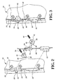
- Each engaging assembly 30 has a first elastic member 34 and a first engaging member 32 received in the accommodating room 22 of the mounting assembly 1.
- the first elastic member 34 is located between the first engaging member 32 and the accommodating room 22.
- a second engaging member 42 is received in the accommodating room 22 of the mounting assembly 1 and a second elastic member 44 is located between the second engaging member 42 and the accommodating room 22.
- the first engaging member 32 includes a first force receiving portion 36 and a first engaging portion 38 located corresponding to the opening 23 of the accommodating room 22.
- the first engaging portion 38 is pushed toward the opening 23 of the accommodating room 22 by the force of the first elastic member 34.
- the second engaging member 42 includes a second force receiving portion 46 and a second engaging portion 48 located corresponding to the opening 23 of the accommodating room 22.
- the second engaging portion 48 is pushed toward the opening 23 of the accommodating room 22 by the force of the second elastic member 44.
- the first force receiving portion 36 of the first engaging member 32 includes a first force receiving inclined surface
- the second force receiving portion 46 includes a second force receiving inclined surface.
- the first and second elastic members 34, 44 are compression springs.
- the first and second elastic members 34a, 44a are plate springs
- the first and second engaging members 32a, 42a have an insertion hole 33a, 43a so as to receive an end of the first and second springs 34a, 44a respectively.
- the first and second springs 34b, 44b are integral to the first and second engaging members 32b, 42b.
- the first housing 50 is connected to first part 10 of the mounting assembly 1 and includes multiple assembling portions 52. Each assembling portion 52 is located corresponding to the first engaging portion 38 of the first engaging member 32 so as to be connected to the first engaging member 32, as shown in Figs. 4 and 5 .
- the assembling portion 52 of the first housing 50 has an engaging hole 53, and the first engaging portion 38 of the first engaging member 32 has a first engaging inclined surface 39 which is located corresponding to the assembling portion 52 of the first housing 50 so as to guide the assembling portion 52 of the first housing 50 to be connected with the first engaging portion 38 of the first engaging member 32.
- the second housing 60 is connected to the second part 20 of the mounting assembly 1 and includes multiple connection portions 62. Each connection portion 62 is located corresponding to the second engaging portion 48 of the second engaging member 42 and is connected with the second engaging member 42, as shown in Figs. 4 and 5 .
- the connection portion 62 of the second housing 60 has an engaging hole 63 and the second engaging portion 48 of the second engaging member 42 has a second engaging inclined surface 49 which guides the connection portion 62 of the second housing 60 to be connected with the second engaging portion 48 of the second engaging member 42.
- the guiding members 70 are located in the side rooms 24 respectively and each guiding member 70 has a first guiding portion 72 and a second guiding portion 74.
- the first guiding portion 72 is located corresponding to the first force receiving portion 36.
- the first engaging member 32 is moved and compresses the first elastic member 34, such that the first engaging portion 38 is disengaged from the assembling portion 52 of the first housing 50.
- the second guiding portion 74 is located corresponding to the second force receiving portion 46 of the second engaging member 42.
- the second engaging member 42 When the second guiding portion 74 is guided along the second force receiving portion 46 and moved to a second position, the second engaging member 42 is moved and compresses the second elastic member 44, so that the second engaging portion 48 is disengaged from the connection portion 62 of the second housing 60.
- the first guiding portion 72 of the guiding member 70 has a first guiding inclined surface which is slidably engaged with the first force receiving inclined surface of the first engaging member 32 to move the first engaging member 32 relative to the guiding member 70.
- the second guiding portion 74 of the guiding member 70 includes a second guiding inclined surface which is slidably engaged with the second force receiving inclined surface of the second engaging member 42 to move the second engaging member 42 relative to the guiding member 70.
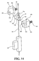
- connection member 80 is connected with the guiding members 70 and includes a release portion 82 which is located corresponding to the slot 26 of the mounting assembly 1. When the user operates the release portion 82, the connection member 80 is moved to move the guiding members 70.
- the connection member 80 is a rope located in the path 28 of the mounting assembly 1.
- the force of the first elastic member 34 pushes the first engaging member 32 so that the first engaging portion 38 of the first engaging member 32 is engaged with the assembling portion 52 of the first housing 50.
- the force of the second elastic member 44 pushes the second engaging member 42 so that the second engaging portion 48 is engaged with the assembling portion 62 of the second housing 60.
- the first housing 50 can be disengaged from the first part 10 of the mounting assembly 1.
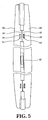
- the user operates the release portion 82 or the connection member 80 from an initial position toward a first direction as indicated by F1, and moves it to a first position, the connection member 80 moves the guiding member 70 so that the first guiding portion 72 of the guiding member 70 is guided along the first force receiving portion 36 and the first engaging member 32 is moved and compresses the first elastic member 34, such that the first engaging portion 38 of the first engaging member 32 is disengaged from the assembling portion 52 of the first housing 50. Therefore, the first housing 50 can be easily disengaged from the first part 10 of the mounting assembly 1, or a new first housing 50 can be replaced.
- the first engaging member 32 is disengaged from the assembling portion 52 of the first housing 50.
- the connection member 80 as a loop is connected to the guiding members 70 which are moved with the first engaging members 32.
- the second housing 60 can be disengaged from the second part 20 of the mounting assembly 1.
- the user operates the release portion 82 or the connection member 80 from an initial position toward a second direction as indicated by F2, and moves it to a second position, the connection member 80 moves the guiding member 70 so that the second guiding portion 74 of the guiding member 70 is guided along the second force receiving portion 46 and the second engaging member 42 is moved and compresses the second elastic member 44, such that the second engaging portion 48 of the second engaging member 42 is disengaged from the assembling portion 62 of the second housing 60. Therefore, the second housing 60 can be easily disengaged from the second part 20 of the mounting assembly 1, or a new second housing 60 can be replaced. As shown in Fig. 9 , the connection member 80 as a loop is connected to the guiding members 70 which are moved with the second engaging members 42.
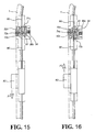
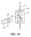
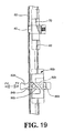
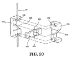
- Figs. 14 to 16 show a fourth embodiment of the present invention, which includes a first engaging member 32c and a second engaging member 42c.
- the first and second engaging members 32c, 42c include first and second guiding slots 33c, 43c and first and second force receiving portions 36c, 46c, respectively.
- the first force receiving portion 36c tilts towards the same direction as that of the first engaging portion 38c.
- the second force receiving portion 46c tilts towards the same direction as that of the second engaging portion 48c.
- a guiding member 70c is movably connected to the connection member 80.
- the connection member 80 has a connecting block 81 which is movably connected to the guiding member 70c.
- the guiding member 70c includes a first cam 71c and a second cam 72c.
- the first cam 71 c is located corresponding to the first force receiving portion 36c of the first engaging member 32c
- the second cam 72c is located corresponding to the second force receiving portion 46c of the second engaging member 42c.
- the first and second cams 71 c, 72c include first and second shafts 73c, 74c which respectively extend through the first and second guiding slots 33c, 43c of the first and second engaging members 32c, 42c and are pivotally connected to the mounting assembly 1.
- the first and second shafts 73c, 74c can be two ends of a single shaft which extends through the guiding member 70c.
- the first and second guiding slots 33c, 43c provide the first and second engaging member 32c, 42c a travel distance relative to the first and second shafts 73c, 74c of the guiding member 70c.
- connection member 80 rotates the guiding member 70c whose second cam 72c pushes the second force receiving portion 46c of the second engaging member 42c, so that the second engaging member 42c moves and compresses the second elastic member 44 to release the second engaging member 42c.
- the release portion 82a includes a pivoted end and an operation end opposite to the pivoted end, so that the release portion 82a can be operated to swing toward the first direction F1 or the second direction F2 so as to move the connection member 80.
- the guiding member 70 moves the second engaging member 42 or the first engaging member 32 to be engaged with the second housing 60 or the first housing 50.
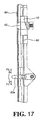
- the release portion 82b includes a first portion 84b and a second portion 86b, and a sliding member 88b connected to the connection member 80.
- the sliding member 88b includes a first inclined surface 90b which is located corresponding to the first portion 84b and a second inclined portion 92b is located corresponding to the second portion 86b.
- first portion 84b will be moved along the first inclined surface 90b of the sliding member 88b to move the sliding member 88b upward and then to move the connection member 80.
- second portion 86b will be moved along the second inclined surface 92b of the sliding member 88b to move the sliding member 86b downward and then to move the connection member 80.
- the sliding member 88b includes a first piece 89b and a second piece 91 b.
- the first piece 89b includes a first inclined surface 90b and multiple protrusions 93b.
- the second piece 91b includes a second inclined surface 92b and multiple recesses 94b which are located corresponding to the protrusions 93b. The engagement between the protrusions 93b and the recesses 94b connects the first and second pieces 89b, 91 b.
- the housing assembly of the present invention allows the manufacturers to assemble the housing assembly without using tools especially the screw drives and can assemble the housing assembly quickly to reduce the time required and to reduce the assembling cost. Especially, the users can easily replace the first and second housings.
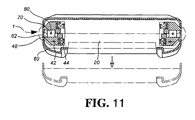
- An electronic unit (not shown) can be installed between the first and second parts 10, 20.
- a third elastic member 96 is provided between the first part 10 and the first housing 50 to securely connect the first housing 50.
- the first housing 50 can be separated from the first part 10 by the force of the third elastic member 96.
- a fourth elastic member 98 is provided between the second part 20 and the second housing 60 to securely connect the second housing 60.
- the second housing 60 can be separated from the second part 20 by the force of the fourth elastic member 98.
- the present invention allows the users to replace or disassemble the first and second housing and the electronic unit is an electronic communication unit, especially to the cellular phone.
- the replaceable first and second housings the users can enjoy the change of the facing plate of the cellular phones to show the variety of appearances of the portable communication products.
Landscapes
- Engineering & Computer Science (AREA)
- Signal Processing (AREA)
- Telephone Set Structure (AREA)
- Casings For Electric Apparatus (AREA)
- Electrophonic Musical Instruments (AREA)
- Fittings On The Vehicle Exterior For Carrying Loads, And Devices For Holding Or Mounting Articles (AREA)
- Coupling Device And Connection With Printed Circuit (AREA)
- Brushes (AREA)
Claims (13)
- Ein Gehäusezusammenbau für ein Elektronikgerät, aufgebaut aus:einem Montagegehäuse (1) aus einem ersten Gehäuseteil (10), an dem ein zweites Gehäuseteil (20) befestigt ist, und das mit mehreren Aufnahmelücken (22) versehen ist, wobei diese Aufnahmelücken (22) zwischen dem ersten und zweiten Gehäuseteil (10, 20) gebildet sind und diese Aufnahmelücken (22) je eine Öffnung (23) aufweisen;einem ersten Gehäuse (50), das mit dem Montagegehäuse (1) befestigt ist, wobei dieses erste Gehäuse (50) mit mehreren Befestigungslaschen (52) versehen ist;dadurch gekennzeichnet, dass:zwischen dem ersten und zweiten Gehäuseteil (10, 20) eine Einkerbung (26) gebildet ist;mehrere Einrückelemente (30) mit je einem ersten elastischen Element (34) und einem ersten Einrückteil (32) versehen sind, wobei dieses erste Einrückteil (32) in eine der Aufnahmelücken (22) des Montagegehäuses (1) eingerückt und mit einem ersten kräfteaufnehmenden Element (36) und einer ersten Einrücklasche (38) an eine der Öffnung (23) an übereinstimmender Stelle mit eine der Aufnahmelücken (22) gebildet ist;mehrere Führungselemente (70) mit einem ersten Führungsteil (72) versehen sind, das an einer mit dem ersten kräfteaufnehmenden Element (36) des ersten Einrückteils (32) an übereinstimmender Stelle mit mehreren Einrückelementen (30) gebildet ist; undan einem Verbundelement (80) mehrere Führungselemente (70) befestigt sind, wobei dieses Verbundelement (80) an eine der Einkerbung (26) des Montagegehäuses (1) an einer übereinstimmenden Stelle mit einem Ausrückelement (82) versehen ist;dadurch gekennzeichnet, dass die Befestigungslaschen (52) an eine der ersten Einrücklaschen (38) des ersten Einrückteils (32) an eine der Einrückelementen (30) entsprechenden Stelle gebildet sind;dadurch gekennzeichnet, dass die erste Einrücklasche (38) des ersten Einrückteils (32) durch eine Kraft des ersten elastischen Elements (34) in eine der Befestigungslaschen (52) des ersten Gehäuses (50) eingerückt wird;dadurch gekennzeichnet, dass auf das erste Führungsteil (72) der Führungselemente (70) eine Kraft ausgeübt wird, um das erste kräfteaufnehmende Element (36) des ersten Einrückteils (32) in eine Position zu bewegen, so dass das erste Einrückteil (32) aus einer der Befestigungslaschen (52) des ersten Gehäuses (50) ausgerückt wird.
- Der Gehäusezusammenbau nach Anspruch 1, dadurch gekennzeichnet, dass mit dem ersten und zweiten Gehäuseteil (10, 20) mehrere Seitenlücken (24) und ein Durchlass (28) gebildet werden, wobei sich diese Seitenlücken (24) an einer mit den Aufnahmelücken (22) übereinstimmenden Stelle befinden und der Durchlass (28) an eine mit der Seitenlücken (24) übereinstimmenden Stelle gebildet ist; die Führungselemente (70) in einer jeweiligen Seitenlücke (24) dieser Seitenlücken (24) angeordnet sind und das Verbundelement (80) im Durchlass (28) aufgenommen ist.
- Der Gehäusezusammenbau nach Anspruch 1, dadurch gekennzeichnet, dass das erste Gehäuseteil (10) mit einer Platte (16) aufgebaut ist, von der mehrere Laschen (18) hervorstehen, während das zweite Gehäuseteil (20) mit mehreren Aufnahmelöchern (29) versehen ist, in die die Laschen (18) einrücken.
- Der Gehäusezusammenbau nach Anspruch 1, dadurch gekennzeichnet, dass das erste kräfteaufnehmende Element (36) des ersten Einrückteils (32) eine erste kräfteaufnehmende abgeschrägte Fläche und das erste Führungsteil (72) der Führungselemente (70) je eine erste abgeschrägte Führungsfläche aufweisen, wobei letztere gleitbar mit der ersten kräfteaufnehmenden abgeschrägten Fläche in Berührung kommt, um das erste Einrückteil (32) entsprechend mit einer der Befestigungslaschen (52) des ersten Gehäuses (50) zu verschieben.
- Der Gehäusezusammenbau nach Anspruch 1, dadurch gekennzeichnet, dass die Befestigungslaschen (52) des ersten Gehäuses (50) je mit einem Einrückschlitz (53) versehen ist, während die erste Einrücklasche (38) des ersten Einrückteils (32) der Einrückelementen (30) je eine erste abgeschrägte Einrückfläche (39) aufweist, die sich an einer übereinstimmenden Stelle mit einer Fläche der Befestigungslaschen (52) des ersten Gehäuses (50) befindet, damit diese entsprechende Fläche der Befestigungslaschen (52) des ersten Gehäuses (50) mit der ersten Einrücklasche (38) des ersten Einrückteils (32) der Einrückelementen (30) in Berührung kommt.
- Der Gehäusezusammenbau nach Anspruch 1, dadurch gekennzeichnet, dass das Ausrückteil (82b) mit einem ersten Zapfen (84b) und einem zweiten Zapfen (86b) versehen ist, ein Gleitelement (88b) mit dem Verbundelement (80) befestigt und das Gleitelement (88b) mit einer ersten abgeschrägten Fläche (90b) gebildet ist, die sich mit einer übereinstimmenden Stelle des ersten Zapfens (84b) befindet, während eine zweite abgeschrägte Fläche (92b) mit einer an übereinstimmender Stelle des zweiten Zapfens (86b) befindet.
- Der Gehäusezusammenbau nach Anspruch 1, dadurch gekennzeichnet, dass die Einrückelemente (30) aus einem zweiten elastischen Element (44) und einem zweiten Einrückteil (42) in eine der Aufnahmelücken (22) des Montagegehäuses (1) besteht; das zweite Einrückteil (42) mit einem zweiten kräfteaufnehmenden Element (46) und einer zweiten Einrücklasche (38) gebildet ist, wobei sich die zweite Einrücklasche (38) mit einer übereinstimmenden Stelle der Öffnung (23) eine der Aufnahmelücken (22) befindet; die Führungselemente (70) mit einem zweiten Führungsteil (74) versehen sind, das sich mit einer übereinstimmenden Stelle des zweiten kräfteaufnehmenden Elements (46) des zweiten Einrückteils (42) befindet, während ein zweites Gehäuse (60) mit dem zweiten Gehäuseteil (20) des Montagegehäuses (1) befestigt ist und mehrere Befestigungslaschen (62) aufweist, die sich mit einer übereinstimmenden Stelle der zweiten Einrücklaschen (48) des zweiten Einrückteils (42) gebildet sind.
- Der Gehäusezusammenbau nach Anspruch 7, dadurch gekennzeichnet, dass die Befestigungslaschen (62) des zweiten Gehäuses (60) mit je einem Einrückschlitz (63) versehen sind, während die zweite Einrücklasche (48) des zweiten Einrückteils (42) der Einrückelemente (30) mit einer zweiten abgeschrägten Einrückfläche (49) gebildet sind, mit der die Befestigungslaschen (62) des zweiten Gehäuses (60) geführt werden, damit diese Befestigungslaschen (62) mit der zweiten Einrücklasche (48) des zweiten Einrückteils (42) eines der Einrückelemente (30) in Berührung kommen.
- Der Gehäusezusammenbau nach Anspruch 7, dadurch gekennzeichnet, dass das zweite kräfteaufnehmende Element (46) des zweiten Einrückteils (42) mit einer zweiten abgeschrägten kräfteaufnehmenden Fläche gebildet ist, während das zweite Führungsteil (74) der Führungselemente (70) mit einer zweiten abgeschrägten Führungsfläche versehen ist, die gleitbar mit der zweiten abgeschrägten kräfteaufnehmenden Fläche in Berührung kommt, um das zweite Einrückteil (42) übereinstimmend mit einer der Befestigungslaschen (62) des zweiten Gehäuses (60) zu verschieben.
- Der Gehäusezusammenbau nach Anspruch 7, dadurch gekennzeichnet, dass die ersten und zweiten Einrückteile (32c, 42c) der Einrückelemente (30) mit einem ersten bzw. zweiten Führungsschlitz (33c, 43c) und einem ersten bzw. zweiten kräfteaufnehmenden Element (36c, 46c) versehen sind, wobei die Führungselemente (70c) beweglich mit dem Verbundelement (80) in Berührung sind. Die Führungselemente (70c) sind mit einer ersten Nocke (71c) und einer zweiten Nocke (72c) versehen, wobei sich die erste Nocke (71c) an einer übereinstimmenden Stelle mit dem ersten kräfteaufnehmenden Element (36c) des ersten Einrückteils (32c) und die zweite Nocke (72c) an übereinstimmender Stelle mit dem zweiten kräfteaufnehmenden Element (46c) des zweiten Einrückteils (42c) befinden; die erste und zweite Nocke (71c, 72c) mit einem ersten und zweiten Zapfen (73c, 74c) versehen sind, die durch den ersten und zweiten Führungsschlitz (33c, 43c) des ersten und zweiten Einrückteils (32c, 42c) geschoben und drehbar mit dem Montagegehäuse (1) befestigt sind.
- Der Gehäusezusammenbau nach Anspruch 7, weiter aufgebaut aus einem dritten elastischen Element (96), das zwischen dem ersten Gehäuseteil (10) und dem ersten Gehäuse (50) montiert ist.
- Der Gehäusezusammenbau nach Anspruch 1, dadurch gekennzeichnet, dass das Ausrückteil (82a) mit einem drehbaren Ende und diesem gegenüber mit einem betätigenden Ende gebildet ist.
- Der Gehäusezusammenbau nach Anspruch 11, weiter aufgebaut aus einem vierten elastischen Element (98), das zwischen dem zweiten Gehäusteil (20) und dem zweiten Gehäuse (60) montiert ist.
Applications Claiming Priority (1)
| Application Number | Priority Date | Filing Date | Title |
|---|---|---|---|
| TW097141277A TWI347814B (en) | 2008-10-27 | 2008-10-27 | Housing assembly for an electrical device and assembly method thereof |
Publications (2)
| Publication Number | Publication Date |
|---|---|
| EP2180668A1 EP2180668A1 (de) | 2010-04-28 |
| EP2180668B1 true EP2180668B1 (de) | 2011-05-04 |
Family
ID=41611191
Family Applications (1)
| Application Number | Title | Priority Date | Filing Date |
|---|---|---|---|
| EP09174028A Active EP2180668B1 (de) | 2008-10-27 | 2009-10-26 | Gehäuseanwendung für tragbare elektronische Vorrichtung |
Country Status (7)
| Country | Link |
|---|---|
| US (1) | US8164898B2 (de) |
| EP (1) | EP2180668B1 (de) |
| JP (1) | JP3156572U (de) |
| AT (1) | ATE508576T1 (de) |
| DE (1) | DE602009001231D1 (de) |
| ES (1) | ES2366145T3 (de) |
| TW (1) | TWI347814B (de) |
Cited By (1)
| Publication number | Priority date | Publication date | Assignee | Title |
|---|---|---|---|---|
| EP2597843A1 (de) | 2011-11-28 | 2013-05-29 | King Slide Works Co., Ltd. | Verriegelungsvorrichtung für Gehäuse einer tragbaren elektronischen Vorrichtung |
Families Citing this family (32)
| Publication number | Priority date | Publication date | Assignee | Title |
|---|---|---|---|---|
| US8264837B2 (en) * | 2010-04-19 | 2012-09-11 | Apple Inc. | Systems and methods for cover assembly retention of a portable electronic device |
| US8801050B2 (en) * | 2011-03-09 | 2014-08-12 | King Slide Works Co., Ltd. | Locking device for case of portable electronic device |
| US8885355B2 (en) * | 2011-07-06 | 2014-11-11 | Apple Inc. | Device having snaps with soldered snap members |
| CN102958304A (zh) * | 2011-08-16 | 2013-03-06 | 华硕电脑股份有限公司 | 可携式电子装置 |
| TWI455674B (zh) * | 2011-10-27 | 2014-10-01 | King Slide Works Co Ltd | 可攜式電子裝置的殼體鎖定構造 |
| US8646818B2 (en) | 2011-11-25 | 2014-02-11 | King Slide Works Co., Ltd. | Locking device for case of portable electronic device |
| CN103491734A (zh) * | 2012-06-11 | 2014-01-01 | 深圳富泰宏精密工业有限公司 | 锁持结构及应用该锁持结构的电子装置 |
| TWI505070B (zh) * | 2013-05-20 | 2015-10-21 | King Slide Technology Co Ltd | 可攜式電子裝置的殼體裝配構造 |
| CN104184849B (zh) * | 2013-05-23 | 2017-03-01 | 川益科技股份有限公司 | 可携式电子装置的壳体总成及壳体装配构造 |
| US9072163B2 (en) * | 2013-06-19 | 2015-06-30 | King Slide Technology Co., Ltd. | Housing assembly for portable electronic device |
| WO2015008368A1 (ja) * | 2013-07-19 | 2015-01-22 | キヤノン株式会社 | 部品の留合せ構造 |
| JP6191338B2 (ja) * | 2013-09-04 | 2017-09-06 | ソニー株式会社 | 筐体および筐体部品 |
| US10133314B2 (en) | 2014-05-26 | 2018-11-20 | Apple Inc. | Portable computing system |
| US10228721B2 (en) | 2014-05-26 | 2019-03-12 | Apple Inc. | Portable computing system |
| US9575514B2 (en) * | 2015-01-09 | 2017-02-21 | Apple Inc. | Enclosure features of a portable computing device |
| CN207586791U (zh) | 2014-09-30 | 2018-07-06 | 苹果公司 | 便携式计算系统 |
| US9955570B2 (en) | 2015-01-09 | 2018-04-24 | Apple Inc. | Features of a flexible connector in a portable computing device |
| US10162390B2 (en) | 2015-01-16 | 2018-12-25 | Apple Inc. | Hybrid acoustic EMI foam for use in a personal computer |
| US11678445B2 (en) | 2017-01-25 | 2023-06-13 | Apple Inc. | Spatial composites |
| KR102826303B1 (ko) | 2017-03-29 | 2025-06-30 | 애플 인크. | 통합형 인터페이스 시스템을 갖는 디바이스 |
| TWI732137B (zh) * | 2017-09-29 | 2021-07-01 | 美商蘋果公司 | 多部件裝置外殼 |
| EP3685253A1 (de) | 2018-05-25 | 2020-07-29 | Apple Inc. | Tragbarer rechner mit dynamischer anzeigeschnittstelle |
| US11175769B2 (en) | 2018-08-16 | 2021-11-16 | Apple Inc. | Electronic device with glass enclosure |
| US10705570B2 (en) | 2018-08-30 | 2020-07-07 | Apple Inc. | Electronic device housing with integrated antenna |
| US11189909B2 (en) | 2018-08-30 | 2021-11-30 | Apple Inc. | Housing and antenna architecture for mobile device |
| US11133572B2 (en) | 2018-08-30 | 2021-09-28 | Apple Inc. | Electronic device with segmented housing having molded splits |
| US11258163B2 (en) | 2018-08-30 | 2022-02-22 | Apple Inc. | Housing and antenna architecture for mobile device |
| CN114399013B (zh) | 2019-04-17 | 2024-11-29 | 苹果公司 | 无线可定位标签 |
| US11838432B2 (en) * | 2019-12-03 | 2023-12-05 | Apple Inc. | Handheld electronic device |
| US12009576B2 (en) | 2019-12-03 | 2024-06-11 | Apple Inc. | Handheld electronic device |
| CN210896389U (zh) * | 2020-03-10 | 2020-06-30 | 京东方科技集团股份有限公司 | 一种显示装置 |
| US12193839B2 (en) | 2020-05-13 | 2025-01-14 | Apple Inc. | Wearable electronic device with glass shell |
Family Cites Families (8)
| Publication number | Priority date | Publication date | Assignee | Title |
|---|---|---|---|---|
| US5469982A (en) * | 1994-08-23 | 1995-11-28 | Motorola, Inc. | Four-sided housing latch |
| US5946395A (en) * | 1997-08-29 | 1999-08-31 | Motorola, Inc. | Housing assembly for an electronic device |
| US20030219117A1 (en) * | 2002-05-22 | 2003-11-27 | Huei-Hsin Sun | Device for fastening body of cellular phone or PDA to its base |
| TW524423U (en) * | 2002-06-28 | 2003-03-11 | Hon Hai Prec Ind Co Ltd | An enclosure assembly for portable electronic device |
| TW534572U (en) * | 2002-09-11 | 2003-05-21 | Benq Corp | Housing assembly of portable electronic device |
| TW534574U (en) * | 2002-09-18 | 2003-05-21 | Benq Corp | House assembly of portable electronic device |
| US6876543B2 (en) * | 2003-03-07 | 2005-04-05 | Motorola, Inc. | Housing for a communication device and method assembling the same |
| TWM243896U (en) * | 2003-08-15 | 2004-09-11 | Hon Hai Prec Ind Co Ltd | Repalceable panel for handset |
-
2008
- 2008-10-27 TW TW097141277A patent/TWI347814B/zh active
-
2009
- 2009-10-23 JP JP2009007533U patent/JP3156572U/ja not_active Expired - Lifetime
- 2009-10-26 US US12/605,494 patent/US8164898B2/en active Active
- 2009-10-26 DE DE602009001231T patent/DE602009001231D1/de active Active
- 2009-10-26 EP EP09174028A patent/EP2180668B1/de active Active
- 2009-10-26 AT AT09174028T patent/ATE508576T1/de not_active IP Right Cessation
- 2009-10-26 ES ES09174028T patent/ES2366145T3/es active Active
Cited By (1)
| Publication number | Priority date | Publication date | Assignee | Title |
|---|---|---|---|---|
| EP2597843A1 (de) | 2011-11-28 | 2013-05-29 | King Slide Works Co., Ltd. | Verriegelungsvorrichtung für Gehäuse einer tragbaren elektronischen Vorrichtung |
Also Published As
| Publication number | Publication date |
|---|---|
| US8164898B2 (en) | 2012-04-24 |
| ES2366145T3 (es) | 2011-10-17 |
| TWI347814B (en) | 2011-08-21 |
| US20100103600A1 (en) | 2010-04-29 |
| JP3156572U (ja) | 2010-01-07 |
| EP2180668A1 (de) | 2010-04-28 |
| ATE508576T1 (de) | 2011-05-15 |
| DE602009001231D1 (de) | 2011-06-16 |
| TW201018354A (en) | 2010-05-01 |
Similar Documents
| Publication | Publication Date | Title |
|---|---|---|
| EP2180668B1 (de) | Gehäuseanwendung für tragbare elektronische Vorrichtung | |
| EP2262204B1 (de) | Gehäuseanordnung für elektronische Vorrichtung | |
| US8614897B2 (en) | Chip card holding mechanism and portable electronic device using the same | |
| US6071640A (en) | Battery mounting assembly for a radio | |
| US20100092847A1 (en) | Battery cover latching mechanism and portable electronic device using same | |
| US20090246609A1 (en) | Battery cover latch mechanism and portable electronic device using same | |
| US7914919B2 (en) | Battery fastening assembly | |
| US20070205010A1 (en) | Mounting apparatus for data storage device | |
| US20100130268A1 (en) | Battery cover latch mechanism and portable electronic device using same | |
| US8205310B2 (en) | Battery cover latch assembly | |
| US20090258287A1 (en) | Battery cover assembly for electronic device | |
| US8252444B2 (en) | Portable electronic device with battery cover | |
| KR101850150B1 (ko) | 휴대용 통신 장치 | |
| US7550226B2 (en) | Battery cover assembly for portable electronic device | |
| US20100081043A1 (en) | Battery cover latching mechanism | |
| US20110095547A1 (en) | Battery cover latching mechanism | |
| US20100119925A1 (en) | Battery cover assembly for portable electronic device | |
| US20090059482A1 (en) | Electronic device | |
| US8165650B2 (en) | Portable electronic device | |
| US8218316B2 (en) | Portable electronic device with battery cover | |
| US20100320200A1 (en) | Sliding mechanism for portable electronic device | |
| CN101730405B (zh) | 电子装置的壳体组件 | |
| US7991445B2 (en) | Battery cover latching mechanism and portable electronic device using the same | |
| US8247104B2 (en) | Battery cover mechanism | |
| JP2009044041A (ja) | 電子機器用筺体の構造 |
Legal Events
| Date | Code | Title | Description |
|---|---|---|---|
| PUAI | Public reference made under article 153(3) epc to a published international application that has entered the european phase |
Free format text: ORIGINAL CODE: 0009012 |
|
| AK | Designated contracting states |
Kind code of ref document: A1 Designated state(s): AT BE BG CH CY CZ DE DK EE ES FI FR GB GR HR HU IE IS IT LI LT LU LV MC MK MT NL NO PL PT RO SE SI SK SM TR |
|
| AX | Request for extension of the european patent |
Extension state: AL BA RS |
|
| GRAP | Despatch of communication of intention to grant a patent |
Free format text: ORIGINAL CODE: EPIDOSNIGR1 |
|
| GRAC | Information related to communication of intention to grant a patent modified |
Free format text: ORIGINAL CODE: EPIDOSCIGR1 |
|
| 17P | Request for examination filed |
Effective date: 20100906 |
|
| GRAC | Information related to communication of intention to grant a patent modified |
Free format text: ORIGINAL CODE: EPIDOSCIGR1 |
|
| GRAS | Grant fee paid |
Free format text: ORIGINAL CODE: EPIDOSNIGR3 |
|
| GRAA | (expected) grant |
Free format text: ORIGINAL CODE: 0009210 |
|
| AK | Designated contracting states |
Kind code of ref document: B1 Designated state(s): AT BE BG CH CY CZ DE DK EE ES FI FR GB GR HR HU IE IS IT LI LT LU LV MC MK MT NL NO PL PT RO SE SI SK SM TR |
|
| REG | Reference to a national code |
Ref country code: GB Ref legal event code: FG4D |
|
| REG | Reference to a national code |
Ref country code: CH Ref legal event code: EP |
|
| REG | Reference to a national code |
Ref country code: IE Ref legal event code: FG4D |
|
| REF | Corresponds to: |
Ref document number: 602009001231 Country of ref document: DE Date of ref document: 20110616 Kind code of ref document: P |
|
| REG | Reference to a national code |
Ref country code: DE Ref legal event code: R096 Ref document number: 602009001231 Country of ref document: DE Effective date: 20110616 |
|
| REG | Reference to a national code |
Ref country code: NL Ref legal event code: VDEP Effective date: 20110504 |
|
| REG | Reference to a national code |
Ref country code: ES Ref legal event code: FG2A Ref document number: 2366145 Country of ref document: ES Kind code of ref document: T3 Effective date: 20111017 |
|
| PG25 | Lapsed in a contracting state [announced via postgrant information from national office to epo] |
Ref country code: NO Free format text: LAPSE BECAUSE OF FAILURE TO SUBMIT A TRANSLATION OF THE DESCRIPTION OR TO PAY THE FEE WITHIN THE PRESCRIBED TIME-LIMIT Effective date: 20110804 Ref country code: SE Free format text: LAPSE BECAUSE OF FAILURE TO SUBMIT A TRANSLATION OF THE DESCRIPTION OR TO PAY THE FEE WITHIN THE PRESCRIBED TIME-LIMIT Effective date: 20110504 Ref country code: LT Free format text: LAPSE BECAUSE OF FAILURE TO SUBMIT A TRANSLATION OF THE DESCRIPTION OR TO PAY THE FEE WITHIN THE PRESCRIBED TIME-LIMIT Effective date: 20110504 Ref country code: PT Free format text: LAPSE BECAUSE OF FAILURE TO SUBMIT A TRANSLATION OF THE DESCRIPTION OR TO PAY THE FEE WITHIN THE PRESCRIBED TIME-LIMIT Effective date: 20110905 |
|
| PG25 | Lapsed in a contracting state [announced via postgrant information from national office to epo] |
Ref country code: BE Free format text: LAPSE BECAUSE OF FAILURE TO SUBMIT A TRANSLATION OF THE DESCRIPTION OR TO PAY THE FEE WITHIN THE PRESCRIBED TIME-LIMIT Effective date: 20110504 Ref country code: AT Free format text: LAPSE BECAUSE OF FAILURE TO SUBMIT A TRANSLATION OF THE DESCRIPTION OR TO PAY THE FEE WITHIN THE PRESCRIBED TIME-LIMIT Effective date: 20110504 Ref country code: CY Free format text: LAPSE BECAUSE OF FAILURE TO SUBMIT A TRANSLATION OF THE DESCRIPTION OR TO PAY THE FEE WITHIN THE PRESCRIBED TIME-LIMIT Effective date: 20110504 Ref country code: FI Free format text: LAPSE BECAUSE OF FAILURE TO SUBMIT A TRANSLATION OF THE DESCRIPTION OR TO PAY THE FEE WITHIN THE PRESCRIBED TIME-LIMIT Effective date: 20110504 Ref country code: SI Free format text: LAPSE BECAUSE OF FAILURE TO SUBMIT A TRANSLATION OF THE DESCRIPTION OR TO PAY THE FEE WITHIN THE PRESCRIBED TIME-LIMIT Effective date: 20110504 Ref country code: IS Free format text: LAPSE BECAUSE OF FAILURE TO SUBMIT A TRANSLATION OF THE DESCRIPTION OR TO PAY THE FEE WITHIN THE PRESCRIBED TIME-LIMIT Effective date: 20110904 Ref country code: LV Free format text: LAPSE BECAUSE OF FAILURE TO SUBMIT A TRANSLATION OF THE DESCRIPTION OR TO PAY THE FEE WITHIN THE PRESCRIBED TIME-LIMIT Effective date: 20110504 |
|
| PG25 | Lapsed in a contracting state [announced via postgrant information from national office to epo] |
Ref country code: NL Free format text: LAPSE BECAUSE OF FAILURE TO SUBMIT A TRANSLATION OF THE DESCRIPTION OR TO PAY THE FEE WITHIN THE PRESCRIBED TIME-LIMIT Effective date: 20110504 |
|
| PG25 | Lapsed in a contracting state [announced via postgrant information from national office to epo] |
Ref country code: CZ Free format text: LAPSE BECAUSE OF FAILURE TO SUBMIT A TRANSLATION OF THE DESCRIPTION OR TO PAY THE FEE WITHIN THE PRESCRIBED TIME-LIMIT Effective date: 20110504 Ref country code: EE Free format text: LAPSE BECAUSE OF FAILURE TO SUBMIT A TRANSLATION OF THE DESCRIPTION OR TO PAY THE FEE WITHIN THE PRESCRIBED TIME-LIMIT Effective date: 20110504 |
|
| PG25 | Lapsed in a contracting state [announced via postgrant information from national office to epo] |
Ref country code: SK Free format text: LAPSE BECAUSE OF FAILURE TO SUBMIT A TRANSLATION OF THE DESCRIPTION OR TO PAY THE FEE WITHIN THE PRESCRIBED TIME-LIMIT Effective date: 20110504 Ref country code: PL Free format text: LAPSE BECAUSE OF FAILURE TO SUBMIT A TRANSLATION OF THE DESCRIPTION OR TO PAY THE FEE WITHIN THE PRESCRIBED TIME-LIMIT Effective date: 20110504 |
|
| PLBE | No opposition filed within time limit |
Free format text: ORIGINAL CODE: 0009261 |
|
| STAA | Information on the status of an ep patent application or granted ep patent |
Free format text: STATUS: NO OPPOSITION FILED WITHIN TIME LIMIT |
|
| 26N | No opposition filed |
Effective date: 20120207 |
|
| PG25 | Lapsed in a contracting state [announced via postgrant information from national office to epo] |
Ref country code: MC Free format text: LAPSE BECAUSE OF NON-PAYMENT OF DUE FEES Effective date: 20111031 Ref country code: HR Free format text: LAPSE BECAUSE OF FAILURE TO SUBMIT A TRANSLATION OF THE DESCRIPTION OR TO PAY THE FEE WITHIN THE PRESCRIBED TIME-LIMIT Effective date: 20111123 Ref country code: IT Free format text: LAPSE BECAUSE OF FAILURE TO SUBMIT A TRANSLATION OF THE DESCRIPTION OR TO PAY THE FEE WITHIN THE PRESCRIBED TIME-LIMIT Effective date: 20110504 |
|
| REG | Reference to a national code |
Ref country code: DE Ref legal event code: R097 Ref document number: 602009001231 Country of ref document: DE Effective date: 20120207 |
|
| REG | Reference to a national code |
Ref country code: FR Ref legal event code: ST Effective date: 20120629 |
|
| REG | Reference to a national code |
Ref country code: IE Ref legal event code: MM4A |
|
| PG25 | Lapsed in a contracting state [announced via postgrant information from national office to epo] |
Ref country code: FR Free format text: LAPSE BECAUSE OF NON-PAYMENT OF DUE FEES Effective date: 20111102 |
|
| PG25 | Lapsed in a contracting state [announced via postgrant information from national office to epo] |
Ref country code: IE Free format text: LAPSE BECAUSE OF NON-PAYMENT OF DUE FEES Effective date: 20111026 |
|
| PG25 | Lapsed in a contracting state [announced via postgrant information from national office to epo] |
Ref country code: MK Free format text: LAPSE BECAUSE OF FAILURE TO SUBMIT A TRANSLATION OF THE DESCRIPTION OR TO PAY THE FEE WITHIN THE PRESCRIBED TIME-LIMIT Effective date: 20110504 Ref country code: MT Free format text: LAPSE BECAUSE OF FAILURE TO SUBMIT A TRANSLATION OF THE DESCRIPTION OR TO PAY THE FEE WITHIN THE PRESCRIBED TIME-LIMIT Effective date: 20110504 |
|
| PG25 | Lapsed in a contracting state [announced via postgrant information from national office to epo] |
Ref country code: SM Free format text: LAPSE BECAUSE OF FAILURE TO SUBMIT A TRANSLATION OF THE DESCRIPTION OR TO PAY THE FEE WITHIN THE PRESCRIBED TIME-LIMIT Effective date: 20110504 |
|
| PG25 | Lapsed in a contracting state [announced via postgrant information from national office to epo] |
Ref country code: LU Free format text: LAPSE BECAUSE OF NON-PAYMENT OF DUE FEES Effective date: 20111026 |
|
| PG25 | Lapsed in a contracting state [announced via postgrant information from national office to epo] |
Ref country code: BG Free format text: LAPSE BECAUSE OF FAILURE TO SUBMIT A TRANSLATION OF THE DESCRIPTION OR TO PAY THE FEE WITHIN THE PRESCRIBED TIME-LIMIT Effective date: 20110804 |
|
| PG25 | Lapsed in a contracting state [announced via postgrant information from national office to epo] |
Ref country code: TR Free format text: LAPSE BECAUSE OF FAILURE TO SUBMIT A TRANSLATION OF THE DESCRIPTION OR TO PAY THE FEE WITHIN THE PRESCRIBED TIME-LIMIT Effective date: 20110504 |
|
| PG25 | Lapsed in a contracting state [announced via postgrant information from national office to epo] |
Ref country code: HU Free format text: LAPSE BECAUSE OF FAILURE TO SUBMIT A TRANSLATION OF THE DESCRIPTION OR TO PAY THE FEE WITHIN THE PRESCRIBED TIME-LIMIT Effective date: 20110504 |
|
| PG25 | Lapsed in a contracting state [announced via postgrant information from national office to epo] |
Ref country code: HR Free format text: LAPSE BECAUSE OF FAILURE TO SUBMIT A TRANSLATION OF THE DESCRIPTION OR TO PAY THE FEE WITHIN THE PRESCRIBED TIME-LIMIT Effective date: 20110504 |
|
| REG | Reference to a national code |
Ref country code: CH Ref legal event code: PL |
|
| PG25 | Lapsed in a contracting state [announced via postgrant information from national office to epo] |
Ref country code: LI Free format text: LAPSE BECAUSE OF NON-PAYMENT OF DUE FEES Effective date: 20131031 Ref country code: CH Free format text: LAPSE BECAUSE OF NON-PAYMENT OF DUE FEES Effective date: 20131031 |
|
| PG25 | Lapsed in a contracting state [announced via postgrant information from national office to epo] |
Ref country code: GR Free format text: LAPSE BECAUSE OF FAILURE TO SUBMIT A TRANSLATION OF THE DESCRIPTION OR TO PAY THE FEE WITHIN THE PRESCRIBED TIME-LIMIT Effective date: 20110504 |
|
| PGFP | Annual fee paid to national office [announced via postgrant information from national office to epo] |
Ref country code: DE Payment date: 20210810 Year of fee payment: 13 |
|
| REG | Reference to a national code |
Ref country code: DE Ref legal event code: R119 Ref document number: 602009001231 Country of ref document: DE |
|
| PG25 | Lapsed in a contracting state [announced via postgrant information from national office to epo] |
Ref country code: DE Free format text: LAPSE BECAUSE OF NON-PAYMENT OF DUE FEES Effective date: 20230503 |
|
| PGFP | Annual fee paid to national office [announced via postgrant information from national office to epo] |
Ref country code: GB Payment date: 20231011 Year of fee payment: 15 |
|
| PGFP | Annual fee paid to national office [announced via postgrant information from national office to epo] |
Ref country code: ES Payment date: 20231102 Year of fee payment: 15 |
|
| GBPC | Gb: european patent ceased through non-payment of renewal fee |
Effective date: 20241026 |
|
| PG25 | Lapsed in a contracting state [announced via postgrant information from national office to epo] |
Ref country code: GB Free format text: LAPSE BECAUSE OF NON-PAYMENT OF DUE FEES Effective date: 20241026 |
|
| REG | Reference to a national code |
Ref country code: ES Ref legal event code: FD2A Effective date: 20251203 |