EP2180647B1 - Method and apparatus for implementing space frequency block coding in an orthogonal frequency division multiplexing wireless communication system - Google Patents
Method and apparatus for implementing space frequency block coding in an orthogonal frequency division multiplexing wireless communication system Download PDFInfo
- Publication number
- EP2180647B1 EP2180647B1 EP10150446A EP10150446A EP2180647B1 EP 2180647 B1 EP2180647 B1 EP 2180647B1 EP 10150446 A EP10150446 A EP 10150446A EP 10150446 A EP10150446 A EP 10150446A EP 2180647 B1 EP2180647 B1 EP 2180647B1
- Authority
- EP
- European Patent Office
- Prior art keywords
- eigenbeams
- pair
- snr
- channel
- data
- Prior art date
- Legal status (The legal status is an assumption and is not a legal conclusion. Google has not performed a legal analysis and makes no representation as to the accuracy of the status listed.)
- Active
Links
- 238000000034 method Methods 0.000 title claims description 19
- 238000004891 communication Methods 0.000 title claims description 11
- 230000005540 biological transmission Effects 0.000 claims description 10
- 239000000969 carrier Substances 0.000 description 15
- 239000011159 matrix material Substances 0.000 description 13
- 238000010586 diagram Methods 0.000 description 9
- 230000008901 benefit Effects 0.000 description 6
- 238000013507 mapping Methods 0.000 description 6
- 230000003044 adaptive effect Effects 0.000 description 4
- 238000000354 decomposition reaction Methods 0.000 description 4
- 238000012545 processing Methods 0.000 description 4
- 238000000926 separation method Methods 0.000 description 4
- 238000005259 measurement Methods 0.000 description 3
- 238000005457 optimization Methods 0.000 description 3
- 238000007781 pre-processing Methods 0.000 description 2
- 230000003247 decreasing effect Effects 0.000 description 1
- 238000001514 detection method Methods 0.000 description 1
- 230000009977 dual effect Effects 0.000 description 1
- 239000000284 extract Substances 0.000 description 1
- 238000005562 fading Methods 0.000 description 1
- 238000001914 filtration Methods 0.000 description 1
- 238000010606 normalization Methods 0.000 description 1
- 230000002459 sustained effect Effects 0.000 description 1
- 238000012549 training Methods 0.000 description 1
Images

Classifications
-
- H—ELECTRICITY
- H04—ELECTRIC COMMUNICATION TECHNIQUE
- H04L—TRANSMISSION OF DIGITAL INFORMATION, e.g. TELEGRAPHIC COMMUNICATION
- H04L1/00—Arrangements for detecting or preventing errors in the information received
- H04L1/02—Arrangements for detecting or preventing errors in the information received by diversity reception
- H04L1/06—Arrangements for detecting or preventing errors in the information received by diversity reception using space diversity
- H04L1/0606—Space-frequency coding
-
- H—ELECTRICITY
- H04—ELECTRIC COMMUNICATION TECHNIQUE
- H04B—TRANSMISSION
- H04B7/00—Radio transmission systems, i.e. using radiation field
- H04B7/02—Diversity systems; Multi-antenna system, i.e. transmission or reception using multiple antennas
- H04B7/04—Diversity systems; Multi-antenna system, i.e. transmission or reception using multiple antennas using two or more spaced independent antennas
- H04B7/0413—MIMO systems
- H04B7/0417—Feedback systems
-
- H—ELECTRICITY
- H04—ELECTRIC COMMUNICATION TECHNIQUE
- H04B—TRANSMISSION
- H04B7/00—Radio transmission systems, i.e. using radiation field
- H04B7/02—Diversity systems; Multi-antenna system, i.e. transmission or reception using multiple antennas
- H04B7/04—Diversity systems; Multi-antenna system, i.e. transmission or reception using multiple antennas using two or more spaced independent antennas
- H04B7/06—Diversity systems; Multi-antenna system, i.e. transmission or reception using multiple antennas using two or more spaced independent antennas at the transmitting station
- H04B7/0613—Diversity systems; Multi-antenna system, i.e. transmission or reception using multiple antennas using two or more spaced independent antennas at the transmitting station using simultaneous transmission
- H04B7/0615—Diversity systems; Multi-antenna system, i.e. transmission or reception using multiple antennas using two or more spaced independent antennas at the transmitting station using simultaneous transmission of weighted versions of same signal
- H04B7/0619—Diversity systems; Multi-antenna system, i.e. transmission or reception using multiple antennas using two or more spaced independent antennas at the transmitting station using simultaneous transmission of weighted versions of same signal using feedback from receiving side
- H04B7/0621—Feedback content
- H04B7/0626—Channel coefficients, e.g. channel state information [CSI]
-
- H—ELECTRICITY
- H04—ELECTRIC COMMUNICATION TECHNIQUE
- H04B—TRANSMISSION
- H04B7/00—Radio transmission systems, i.e. using radiation field
- H04B7/02—Diversity systems; Multi-antenna system, i.e. transmission or reception using multiple antennas
- H04B7/04—Diversity systems; Multi-antenna system, i.e. transmission or reception using multiple antennas using two or more spaced independent antennas
- H04B7/06—Diversity systems; Multi-antenna system, i.e. transmission or reception using multiple antennas using two or more spaced independent antennas at the transmitting station
- H04B7/0613—Diversity systems; Multi-antenna system, i.e. transmission or reception using multiple antennas using two or more spaced independent antennas at the transmitting station using simultaneous transmission
- H04B7/0615—Diversity systems; Multi-antenna system, i.e. transmission or reception using multiple antennas using two or more spaced independent antennas at the transmitting station using simultaneous transmission of weighted versions of same signal
- H04B7/0619—Diversity systems; Multi-antenna system, i.e. transmission or reception using multiple antennas using two or more spaced independent antennas at the transmitting station using simultaneous transmission of weighted versions of same signal using feedback from receiving side
- H04B7/0621—Feedback content
- H04B7/0632—Channel quality parameters, e.g. channel quality indicator [CQI]
-
- H—ELECTRICITY
- H04—ELECTRIC COMMUNICATION TECHNIQUE
- H04B—TRANSMISSION
- H04B7/00—Radio transmission systems, i.e. using radiation field
- H04B7/02—Diversity systems; Multi-antenna system, i.e. transmission or reception using multiple antennas
- H04B7/04—Diversity systems; Multi-antenna system, i.e. transmission or reception using multiple antennas using two or more spaced independent antennas
- H04B7/06—Diversity systems; Multi-antenna system, i.e. transmission or reception using multiple antennas using two or more spaced independent antennas at the transmitting station
- H04B7/0613—Diversity systems; Multi-antenna system, i.e. transmission or reception using multiple antennas using two or more spaced independent antennas at the transmitting station using simultaneous transmission
- H04B7/0615—Diversity systems; Multi-antenna system, i.e. transmission or reception using multiple antennas using two or more spaced independent antennas at the transmitting station using simultaneous transmission of weighted versions of same signal
- H04B7/0619—Diversity systems; Multi-antenna system, i.e. transmission or reception using multiple antennas using two or more spaced independent antennas at the transmitting station using simultaneous transmission of weighted versions of same signal using feedback from receiving side
- H04B7/0658—Feedback reduction
- H04B7/066—Combined feedback for a number of channels, e.g. over several subcarriers like in orthogonal frequency division multiplexing [OFDM]
-
- H—ELECTRICITY
- H04—ELECTRIC COMMUNICATION TECHNIQUE
- H04L—TRANSMISSION OF DIGITAL INFORMATION, e.g. TELEGRAPHIC COMMUNICATION
- H04L1/00—Arrangements for detecting or preventing errors in the information received
- H04L1/0001—Systems modifying transmission characteristics according to link quality, e.g. power backoff
- H04L1/0002—Systems modifying transmission characteristics according to link quality, e.g. power backoff by adapting the transmission rate
- H04L1/0003—Systems modifying transmission characteristics according to link quality, e.g. power backoff by adapting the transmission rate by switching between different modulation schemes
-
- H—ELECTRICITY
- H04—ELECTRIC COMMUNICATION TECHNIQUE
- H04L—TRANSMISSION OF DIGITAL INFORMATION, e.g. TELEGRAPHIC COMMUNICATION
- H04L1/00—Arrangements for detecting or preventing errors in the information received
- H04L1/0001—Systems modifying transmission characteristics according to link quality, e.g. power backoff
- H04L1/0009—Systems modifying transmission characteristics according to link quality, e.g. power backoff by adapting the channel coding
-
- H—ELECTRICITY
- H04—ELECTRIC COMMUNICATION TECHNIQUE
- H04L—TRANSMISSION OF DIGITAL INFORMATION, e.g. TELEGRAPHIC COMMUNICATION
- H04L1/00—Arrangements for detecting or preventing errors in the information received
- H04L1/0001—Systems modifying transmission characteristics according to link quality, e.g. power backoff
- H04L1/0023—Systems modifying transmission characteristics according to link quality, e.g. power backoff characterised by the signalling
- H04L1/0026—Transmission of channel quality indication
-
- H—ELECTRICITY
- H04—ELECTRIC COMMUNICATION TECHNIQUE
- H04L—TRANSMISSION OF DIGITAL INFORMATION, e.g. TELEGRAPHIC COMMUNICATION
- H04L27/00—Modulated-carrier systems
- H04L27/10—Frequency-modulated carrier systems, i.e. using frequency-shift keying
- H04L27/14—Demodulator circuits; Receiver circuits
- H04L27/156—Demodulator circuits; Receiver circuits with demodulation using temporal properties of the received signal, e.g. detecting pulse width
-
- H—ELECTRICITY
- H04—ELECTRIC COMMUNICATION TECHNIQUE
- H04L—TRANSMISSION OF DIGITAL INFORMATION, e.g. TELEGRAPHIC COMMUNICATION
- H04L27/00—Modulated-carrier systems
- H04L27/26—Systems using multi-frequency codes
- H04L27/2601—Multicarrier modulation systems
- H04L27/2626—Arrangements specific to the transmitter only
- H04L27/2646—Arrangements specific to the transmitter only using feedback from receiver for adjusting OFDM transmission parameters, e.g. transmission timing or guard interval length
-
- H—ELECTRICITY
- H04—ELECTRIC COMMUNICATION TECHNIQUE
- H04L—TRANSMISSION OF DIGITAL INFORMATION, e.g. TELEGRAPHIC COMMUNICATION
- H04L5/00—Arrangements affording multiple use of the transmission path
- H04L5/0001—Arrangements for dividing the transmission path
- H04L5/0003—Two-dimensional division
- H04L5/0005—Time-frequency
- H04L5/0007—Time-frequency the frequencies being orthogonal, e.g. OFDM(A), DMT
-
- H—ELECTRICITY
- H04—ELECTRIC COMMUNICATION TECHNIQUE
- H04L—TRANSMISSION OF DIGITAL INFORMATION, e.g. TELEGRAPHIC COMMUNICATION
- H04L5/00—Arrangements affording multiple use of the transmission path
- H04L5/003—Arrangements for allocating sub-channels of the transmission path
- H04L5/0058—Allocation criteria
- H04L5/006—Quality of the received signal, e.g. BER, SNR, water filling
-
- H—ELECTRICITY
- H04—ELECTRIC COMMUNICATION TECHNIQUE
- H04L—TRANSMISSION OF DIGITAL INFORMATION, e.g. TELEGRAPHIC COMMUNICATION
- H04L27/00—Modulated-carrier systems
- H04L27/0014—Carrier regulation
- H04L2027/0044—Control loops for carrier regulation
- H04L2027/0046—Open loops
-
- H—ELECTRICITY
- H04—ELECTRIC COMMUNICATION TECHNIQUE
- H04L—TRANSMISSION OF DIGITAL INFORMATION, e.g. TELEGRAPHIC COMMUNICATION
- H04L5/00—Arrangements affording multiple use of the transmission path
- H04L5/0001—Arrangements for dividing the transmission path
- H04L5/0014—Three-dimensional division
- H04L5/0023—Time-frequency-space
-
- Y—GENERAL TAGGING OF NEW TECHNOLOGICAL DEVELOPMENTS; GENERAL TAGGING OF CROSS-SECTIONAL TECHNOLOGIES SPANNING OVER SEVERAL SECTIONS OF THE IPC; TECHNICAL SUBJECTS COVERED BY FORMER USPC CROSS-REFERENCE ART COLLECTIONS [XRACs] AND DIGESTS
- Y02—TECHNOLOGIES OR APPLICATIONS FOR MITIGATION OR ADAPTATION AGAINST CLIMATE CHANGE
- Y02B—CLIMATE CHANGE MITIGATION TECHNOLOGIES RELATED TO BUILDINGS, e.g. HOUSING, HOUSE APPLIANCES OR RELATED END-USER APPLICATIONS
- Y02B70/00—Technologies for an efficient end-user side electric power management and consumption
- Y02B70/30—Systems integrating technologies related to power network operation and communication or information technologies for improving the carbon footprint of the management of residential or tertiary loads, i.e. smart grids as climate change mitigation technology in the buildings sector, including also the last stages of power distribution and the control, monitoring or operating management systems at local level
-
- Y—GENERAL TAGGING OF NEW TECHNOLOGICAL DEVELOPMENTS; GENERAL TAGGING OF CROSS-SECTIONAL TECHNOLOGIES SPANNING OVER SEVERAL SECTIONS OF THE IPC; TECHNICAL SUBJECTS COVERED BY FORMER USPC CROSS-REFERENCE ART COLLECTIONS [XRACs] AND DIGESTS
- Y02—TECHNOLOGIES OR APPLICATIONS FOR MITIGATION OR ADAPTATION AGAINST CLIMATE CHANGE
- Y02D—CLIMATE CHANGE MITIGATION TECHNOLOGIES IN INFORMATION AND COMMUNICATION TECHNOLOGIES [ICT], I.E. INFORMATION AND COMMUNICATION TECHNOLOGIES AIMING AT THE REDUCTION OF THEIR OWN ENERGY USE
- Y02D30/00—Reducing energy consumption in communication networks
- Y02D30/50—Reducing energy consumption in communication networks in wire-line communication networks, e.g. low power modes or reduced link rate
Definitions
- the present invention is related to wireless communication systems. More particularly, the present invention is related to a method and apparatus for implementing space frequency block coding (SFBC) in an orthogonal frequency division multiplexing (OFDM) wireless communication system.
- SFBC space frequency block coding
- OFDM orthogonal frequency division multiplexing
- OFDM is a data transmission scheme where data is split into a plurality of smaller streams and each stream is transmitted using a sub-carrier with a smaller bandwidth than the total available transmission bandwidth.
- the efficiency of OFDM depends on choosing these sub-carriers orthogonal to each other. The sub-carriers do not interfere with each other while each is carrying portion of the total user data.
- OFDM systems have advantages over other wireless communication systems.
- the effective data rate on each subcarrier is much smaller. Therefore, the symbol duration is much larger.
- a large symbol duration can tolerate larger delay, and thus is not affected by multipath as severely. Therefore, OFDM symbols can tolerate delay spreads without complicated receiver designs.
- typical wireless systems need complex channel equalization schemes to combat multipath fading.
- OFDM orthogonal subcarriers at the transmitter and receiver can be done by using inverse fast Fourier transform (IFFT) and fast Fourier transform (FFT) engines. Since the IFFT and FFT implementations are well known, OFDM can be implemented easily and does not require complicated receivers.
- IFFT inverse fast Fourier transform
- FFT fast Fourier transform
- MIMO Multiple-input multiple-output
- SNR signal-to-noise ratio
- SFBC is a scheme for transmitting symbols of a space diversity coding on neighboring subcarriers rather than on the same subcarier in the successive time slots.
- the SFBC avoids the problem of fast time variations in space time block coding.
- the channel needs to be constant over the subcarriers that combining takes place.
- US 2003/218973 discloses a method and apparatus combining SFBC and beamforming in MJMO-OFDM systems.
- the present invention is related to a method and apparatus for implementing space frequency block coding (SFBC) in an orthogonal frequency division multiplexing (OFDM) wireless communication system.
- the present invention is applicable to both a closed loop mode and an open loop mode.
- power loading and eigen-beamforming are performed based on channel state information (CSI).
- CSI channel state information
- a channel coded data stream is multiplexed into two or more data streams.
- Power loading is performed based on the CSI on each of the multiplexed data streams.
- SFBC encoding is performed on the data streams for each of the paired subcarriers.
- eigen-beamforming is performed based on the CSI to calculate eigenbeams over multiple transmit antennas.
- the power loading may be performed on two or more SFBC encoding blocks or on each of the eigenmodes. Additionally, the power loading may be performed across subcarriers or subcarrier groups for weak eigenmodes.
- a robust channel estimation can be provided under all channel conditions, with or without channel information feedback, and low complexity is achieved at both transmitter and receiver.
- scalable solutions can be used with any antenna configuration and backward compatibility is provided with enhanced performance with 802.11a/g.
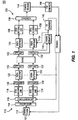
- Figure 1 is a block diagram of an OFDM-MIMO system implementing a closed loop mode.
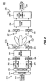
- Figure 2 is a block diagram of a system implementing open loop.
- Figure 3 is a block diagram of a transmitter for depicting power loading.
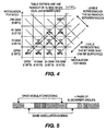
- Figure 4 is a diagram of an exemplary power loading and adaptive modulation and coding mapping between two pairs of modes.
- Figure 5 shows an example of pairing of subcarrier groups for power/bit loading.
- the terminology “station” includes but is not limited to a user equipment, a wireless transmit/receive unit, a fixed or mobile subscriber unit, a pager, or any other type of device capable of operating in a wireless environment.
- the terminology “access point” includes but is not limited to a Node-B, a base station, a site controller or any other type of interfacing device in a wireless environment.
- Embodiments of the present invention provide a transmitter implementing SFBC MIMO coding and receiver matched filtering. Embodiments also provide transmitter channel precoding and receiver antenna processing as well as channel decomposition functions.
- the closed loop is used when channel state information (CSI) is available to the transmitter.
- the open loop is used when CSI is not available.
- a variant may be used for transmission to legacy STA where it provides diversity benefits.
- CSI is used to create virtual independent channels by decomposing and diagonalizing the channel matrix and by precoding at the transmitter.
- the present invention employs a space-frequency orthogonal MIMO coding in the transmitter at the input to the channel precoder to increase robustness at the cost of decreasing data rate.
- Any coding scheme in MIMO has to deal with the diversity versus multiplexing gain trade off. It is desirable to have a trade off scheme that is best suited to particular channel statistics.
- An SFBC is chosen due to low mobility and the long coherence time of the channel. This scheme allows for receiver implementation simpler than an MMSE receiver. The combined solution enables higher throughput over a larger range.
- Embodiments of the present invention allow for per subcarrier power/bit loading and maintains a sustained robust link through closed loop operation with channel state feedback. Another potential benefit is that it is easily scalable to any number of antennas at both transmitter and receiver.
- the CSI can be obtained at the transmitter either by feedback from the receiver or through exploiting channel reciprocity.
- Channel reciprocity is useful for mainly TDD based systems. In this case it is possible for the transmitter and receiver to independently estimate and decompose the channel.
- the channel update rate can be lowered when the SNR is high resulting in a reduced feedback bandwidth load. Latency requirements and feedback data rates are typically not significant to the inherent frequency non-selectivity of eigenvalues.
- the closed loop mode requires calibrations of the transmitter to compensate for amplitude and phase differences of the estimated channels in the uplink and downlink directions. This is done infrequently, for example during STA association or under application control, and can use channel reciprocity for the estimation of the channel at both ends.
- a CQI (or SNR) per eigen-beam is fed back to the transmitter to support adaptive rate control.
- FIG. 1 is a block diagram of an OFDM-MIMO system 100 implementing a closed loop mode.
- the system 100 comprises a transmitter 110 and a receiver 130.
- the transmitter 110 comprises a channel encoder 112, a multiplexer 114, a power loading unit 116, a plurality of SFBC encoding units 118, a plurality of serial-to-parallel (S/P) converters 120, a plurality of eigen-beamformers 122, a plurality of IFFT units 124 and a plurality of transmit antennas (not shown).
- the channel encoder 112 encodes data preferably in accordance with a channel quality indicator (CQI) which is sent from the receiver 130.
- the CQI is used to determine a coding rate and modulation scheme per subcarrier or group of sub-carriers.
- the coded data stream is multiplexed by the multiplexer 114 into two or more data streams.
- CQI channel quality indicator
- the transmit power level of each data stream is adjusted by the power loading unit 116 based on feedback.
- the power loading unit 116 adjusts power levels with respect to the data rate of each eigenbeam to balance the total transmit power over all eigenbeams (or sub-carriers), which will be explained in detail below.
- the SFBC encoding units 118 perform SFBC encoding on the data streams. SFBC encoding is done over eigen-beams and sub-carriers for each data rate that is transmitted. Eigen-beam and sub-carrier pairs are selected to ensure independent channels. OFDM symbols are carried on K sub-carriers. To accommodate SFBC, the sub-carriers are divided into L pairs of sub-carriers (or group of sub-carriers). The bandwidth of each group of sub-carriers should be less than the coherence bandwidth of the channel. However, when combined with eigen-beamforming this restriction is relaxed due to the frequency insensitivity of the eigen-beams.
- the pairs of sub-carrier groups used by the block code are considered independent.
- the coded blocks are multiplexed by the S/P converters 120 and input to the eigen-beamformers 122.
- the eigen-beamformers 122 distribute the eigenbeams to the transmit antennas.
- the IFFT units 124 convert the data in frequency domain to the data in time domain.
- the receiver 130 comprises a plurality of receive antennas (not shown), a plurality of FFT units 132, eigen-beamformers 134, SFBC decoding units 136, a combiner 138, a channel decoder 144, a channel estimator 140, a CSI generator 142 and a CQI generator 146.
- the FFT units 132 convert the received samples to frequency domain and the eigen-beamformer 134, the SFBC decoding unit 136 and a channel decoder 144 perform the opposite operation which is performed at the transmitter 110.
- the combiner 138 combines the SFBC decoding results using maximal ratio combining (MRC).
- the channel estimator 140 generates a channel matrix using a training sequence transmitted from the transmitter and decomposes the channel matrix into two beam-forming unitary matrices U and V , ( U for transmit and V for receive), and a diagonal matrix D per sub-carrier (or per sub-carrier group) by singular value decomposition (SVD) or eigenvalue decomposition.
- the CSI generator 142 generates CSI from the channel estimation results and the CQI generator generates a CQI based on the decoding results. The CSI and the CQI are sent back to the transmitter 110.
- H h 11 h 21 ... h 1 , nT h 21 h 22 ... h 2 , nT ⁇ ⁇ h nR , 1 h nR , 2 ... h nR , nT
- U are eigenvectors of HH H
- V are eigenvectors of H H H
- D is a diagonal matrix of singular values of H (square roots of eigenvalues of HH H ).
- FIG. 2 is a block diagram of a system 200 implementing open loop mode in accordance with the present invention.
- the system 200 comprises a transmitter 210 and a receiver 230.
- a combination of space-frequency coding and spatial spreading in the transmitter 210 provides diversity without requiring CSI.
- a variant of this scheme can be used when operating with legacy 802.11 a/g STAs.
- the transmitter 210 comprises a channel encoder 212, a multiplexer 214, a power loading unit 216, a plurality of SFBC encoding units 218, a plurality of serial-to-parallel (S/P) converters 220, a beamformer network (BFN) 222, a plurality of IFFT units 224 and a plurality of transmit antennas 226.
- the channel encoder 212 uses CQI to determine coding rate and modulation per sub-carrier or group of sub-carriers.
- the coded data stream is multiplexed by the multiplexer 214 into two or more data streams.
- the eigen-beamformer is replaced with the Beam Forming Network (BFN) 222.
- BFN Beam Forming Network
- the BFN 222 forms N beams in space, where N is the number of antennas 226.
- the beams are pseudo-randomly constructed by the BFN matrix operation.
- the independent sub-carrier groups used for the SFBC coding are transmitted on individual beams.
- SFBC coding may not be performed. Instead diversity through beam permutation is performed which improves diversity and therefore the performance of legacy 802.11a/g equipment.
- the receiver 230 comprises receive antennas 231, FFT units 232, a BFN 234, an SFBC decoding and combining unit 236 and a channel decoder 238.
- the FFT units 232 convert the received signal in time domain to the signal in frequency domain.
- the SFBC decoding and combining unit 236 decodes and combines symbols received from subcarrier groups/eigen-beams and converts them from parallel to serial using a priori-knowledge of the constellation size. Symbols are combined using MRC.
- the channel decoder 238 decodes the combined symbol and generates a CQI.
- the spatial processing is a combination of space-frequency coding and eigen-beamforming. This is performed to give the best compromise between the redundancy gains that SFBC affords and the spatial multiplexing that the eigen-beamformer provides.
- the power loading scheme operates across the eigen-modes of the channel matrix.
- SFBC also introduces the constraint that the outputs of the coder have the same power loading no matter what the input power loading is due to the cross-operation inside the coder.
- Figure 3 is a block diagram of a transmitter 110 for depicting power loading.
- Figure 3 illustrates 4x4 case as an example and the first embodiment of the power loading scheme will be explained with reference to 4x4 case.
- the 4x4 case can be extended to any other cases.
- each stream of data is mapped to 2 pairs of power loading/AMC modes.
- the modulation order is selected to be the same for each pair of inputs. This is later mapped to pairs of eigenmodes.
- Output of the power loading unit 116 is applied to the dual 2x2 SFBC encoding units 118 and then passed on to the eigen-beamformer 122.
- the eigen-beamformer 122 maps the inputs to the eigen-modes of the channel through the preprocessing.
- the eigenvalues of the channel matrix are known at the transmitter.
- the eigenmodes are grouped such that half of the eigenmodes with the largest channel energy (or SNIR) are in one group and the other half with the weakest channel energies are in the other. Therefore, the harmonic SNIRs represent the total channel energy of the stronger and weaker eigenmodes. Channel energy is an indication of how robust the eigenmodes are and hence the signal that is carried over these eigenmodes would be. This information is used to apply different adaptive modulation and coding (AMC) and/or different power loading for each half as is explained in more detail subsequently.
- AMC adaptive modulation and coding
- the transmitter 110 has the knowledge of current CSI from which it extracts the eigenvalues and preprocessing matrix. The transmitter 110 also infers the data rate that can be supported in the link, Rb, from the CSI. Then, power loading for a given, acceptable, CQI is an optimization between the number of bits that can be sent per OFDM symbol and the type of modulation that is to be used for each mode.
- Figure 4 is a diagram of an exemplary power loading and adaptive modulation and coding mapping between two pairs of modes.
- the bit rate that can be supported is 24 bits per OFDM symbol for the particular sub-carrier.
- the lowest modulation order satisfying the bit rate is found in Figure 4 as indicated by the dashed arrow.
- first and second modes first pair of coupled modes
- third and fourth modes second pair of coupled modes
- mapping is described for one CQI that is acceptable and for one subcarrier.
- alternative MIMO configurations such as 2x4, 2x2, etc, the same power loading scheme is applicable except that the total number of bits in the table entries are scaled down to represent the transmit capability and that power loading can be done on a single pair of modes.
- the eigenvalues per subcarrier ( ⁇ 1 (k) > ⁇ 2 (k) > ... > ⁇ nT (k)) are ranked and eigenbeams (E 1 , E 2 , ...
- the eigenbeams are paired to create Alamouti space-frequency blocks, such as ⁇ E 1 , E 2 ⁇ 1 , ⁇ E 3 , E 4 ⁇ 2 ,..., ⁇ E 2i-1 , E 2i ⁇ i ... ⁇ E nT-1 , E nT ⁇ nT/2 .
- SNR max the SNR of a pair is greater than SNR max
- the second eigenbeam of the pair is replaced with the eigenbeam with the next lower eigenvalue average until its SNR is less than or equal to SNR min .
- a data rate for each pair of eigenbeams is determined by mapping the SNR of a pair to the data rate for a given quality.
- the required SNRs may be adjusted for all pairs of eigenbeams to compensate for the measurement errors and make the total transmit power be constant.
- another power loading is applied across the sub-carriers or group of subcarriers for weak eigen-modes.
- power loading instead of power loading being applied to all eigenmodes it can be applied only to those that are weaker and hence can benefit from the power loading the most.
- those eigenmodes that are not power loaded can still have SFBC or other coding or can have different AMC settings individually, whereas those eigenmodes that are power loaded share the same AMC setting for instance.
- the eigenmodes of the channel are always ordered in power, from strongest to weakest. By pairing eigenmodes of similar power one may improve the power loading of the channel.
- a spatial processing scheme is configurable to any number of receive and transmit antenna combinations. Depending on the number of antennas on each side, a combination of SFBC and eigen-beamforming options are used.
- the table below summarizes the various configurations supported and the state of the spatial processing and power loading that is applicable to each scenario.
Description
- FIELD OF INVENTION
- The present invention is related to wireless communication systems. More particularly, the present invention is related to a method and apparatus for implementing space frequency block coding (SFBC) in an orthogonal frequency division multiplexing (OFDM) wireless communication system.
- BACKGROUND
- OFDM is a data transmission scheme where data is split into a plurality of smaller streams and each stream is transmitted using a sub-carrier with a smaller bandwidth than the total available transmission bandwidth. The efficiency of OFDM depends on choosing these sub-carriers orthogonal to each other. The sub-carriers do not interfere with each other while each is carrying portion of the total user data.
- OFDM systems have advantages over other wireless communication systems. When the user data is split into streams carried by different sub-carriers, the effective data rate on each subcarrier is much smaller. Therefore, the symbol duration is much larger. A large symbol duration can tolerate larger delay, and thus is not affected by multipath as severely. Therefore, OFDM symbols can tolerate delay spreads without complicated receiver designs. However, typical wireless systems need complex channel equalization schemes to combat multipath fading.
- Another advantage of OFDM is that the generation of orthogonal subcarriers at the transmitter and receiver can be done by using inverse fast Fourier transform (IFFT) and fast Fourier transform (FFT) engines. Since the IFFT and FFT implementations are well known, OFDM can be implemented easily and does not require complicated receivers.
- Multiple-input multiple-output (MIMO) refers to the type of wireless transmission and reception scheme where both a transmitter and a receiver employ more than one antenna. A MIMO system takes advantage of the spatial diversity or spatial multiplexing and improves signal-to-noise ratio (SNR) and increases throughput.
- SFBC is a scheme for transmitting symbols of a space diversity coding on neighboring subcarriers rather than on the same subcarier in the successive time slots. The SFBC avoids the problem of fast time variations in space time block coding. However, the channel needs to be constant over the subcarriers that combining takes place.
The patent documentUS 2003/218973 discloses a method and apparatus combining SFBC and beamforming in MJMO-OFDM systems. - SUMMARY
- The present invention is related to a method and apparatus for implementing space frequency block coding (SFBC) in an orthogonal frequency division multiplexing (OFDM) wireless communication system. The present invention is applicable to both a closed loop mode and an open loop mode. In the closed loop mode, power loading and eigen-beamforming are performed based on channel state information (CSI). A channel coded data stream is multiplexed into two or more data streams. Power loading is performed based on the CSI on each of the multiplexed data streams. SFBC encoding is performed on the data streams for each of the paired subcarriers. Then, eigen-beamforming is performed based on the CSI to calculate eigenbeams over multiple transmit antennas. The power loading may be performed on two or more SFBC encoding blocks or on each of the eigenmodes. Additionally, the power loading may be performed across subcarriers or subcarrier groups for weak eigenmodes.
- in accordance with the present invention, a robust channel estimation can be provided under all channel conditions, with or without channel information feedback, and low complexity is achieved at both transmitter and receiver. In addition, scalable solutions can be used with any antenna configuration and backward compatibility is provided with enhanced performance with 802.11a/g.
- BRIEF DESCRIPTION OF THE DRAWINGS
-
Figure 1 is a block diagram of an OFDM-MIMO system implementing a closed loop mode. -
Figure 2 is a block diagram of a system implementing open loop. -
Figure 3 is a block diagram of a transmitter for depicting power loading. -
Figure 4 is a diagram of an exemplary power loading and adaptive modulation and coding mapping between two pairs of modes. -
Figure 5 shows an example of pairing of subcarrier groups for power/bit loading. - DETAILED DESCRIPTION OF THE PREFERRED EMBODIMENTS
- Hereafter, the terminology "station" (STA) includes but is not limited to a user equipment, a wireless transmit/receive unit, a fixed or mobile subscriber unit, a pager, or any other type of device capable of operating in a wireless environment. When referred to hereafter, the terminology "access point" (AP) includes but is not limited to a Node-B, a base station, a site controller or any other type of interfacing device in a wireless environment.
- The present invention will be described with reference to the drawing figures wherein like numerals represent like elements throughout. It should be noted that figures provided in the present invention are high level functional block diagrams and the functions implemented by the functional blocks may be implemented by more or less blocks. The features of the present invention may be incorporated into an integrated circuit (IC) or be configured in a circuit comprising a multitude of interconnecting components.
- Embodiments of the present invention provide a transmitter implementing SFBC MIMO coding and receiver matched filtering. Embodiments also provide transmitter channel precoding and receiver antenna processing as well as channel decomposition functions.
- There are two modes of operation of the system: a closed loop and an open loop. The closed loop is used when channel state information (CSI) is available to the transmitter. The open loop is used when CSI is not available. A variant may be used for transmission to legacy STA where it provides diversity benefits.
- In the closed loop mode, CSI is used to create virtual independent channels by decomposing and diagonalizing the channel matrix and by precoding at the transmitter. Given the eigenvalue spread of TGn channels the present invention employs a space-frequency orthogonal MIMO coding in the transmitter at the input to the channel precoder to increase robustness at the cost of decreasing data rate. Any coding scheme in MIMO has to deal with the diversity versus multiplexing gain trade off. It is desirable to have a trade off scheme that is best suited to particular channel statistics. An SFBC is chosen due to low mobility and the long coherence time of the channel. This scheme allows for receiver implementation simpler than an MMSE receiver. The combined solution enables higher throughput over a larger range. Embodiments of the present invention allow for per subcarrier power/bit loading and maintains a sustained robust link through closed loop operation with channel state feedback. Another potential benefit is that it is easily scalable to any number of antennas at both transmitter and receiver.
- The CSI can be obtained at the transmitter either by feedback from the receiver or through exploiting channel reciprocity. Channel reciprocity is useful for mainly TDD based systems. In this case it is possible for the transmitter and receiver to independently estimate and decompose the channel. The channel update rate can be lowered when the SNR is high resulting in a reduced feedback bandwidth load. Latency requirements and feedback data rates are typically not significant to the inherent frequency non-selectivity of eigenvalues.
- The closed loop mode requires calibrations of the transmitter to compensate for amplitude and phase differences of the estimated channels in the uplink and downlink directions. This is done infrequently, for example during STA association or under application control, and can use channel reciprocity for the estimation of the channel at both ends. In addition, a CQI (or SNR) per eigen-beam is fed back to the transmitter to support adaptive rate control.
-
Figure 1 is a block diagram of an OFDM-MIMO system 100 implementing a closed loop mode. Thesystem 100 comprises atransmitter 110 and areceiver 130. Thetransmitter 110 comprises achannel encoder 112, amultiplexer 114, apower loading unit 116, a plurality ofSFBC encoding units 118, a plurality of serial-to-parallel (S/P)converters 120, a plurality of eigen-beamformers 122, a plurality ofIFFT units 124 and a plurality of transmit antennas (not shown). Thechannel encoder 112 encodes data preferably in accordance with a channel quality indicator (CQI) which is sent from thereceiver 130. The CQI is used to determine a coding rate and modulation scheme per subcarrier or group of sub-carriers. The coded data stream is multiplexed by themultiplexer 114 into two or more data streams. - The transmit power level of each data stream is adjusted by the
power loading unit 116 based on feedback. Thepower loading unit 116 adjusts power levels with respect to the data rate of each eigenbeam to balance the total transmit power over all eigenbeams (or sub-carriers), which will be explained in detail below. - The
SFBC encoding units 118 perform SFBC encoding on the data streams. SFBC encoding is done over eigen-beams and sub-carriers for each data rate that is transmitted. Eigen-beam and sub-carrier pairs are selected to ensure independent channels. OFDM symbols are carried on K sub-carriers. To accommodate SFBC, the sub-carriers are divided into L pairs of sub-carriers (or group of sub-carriers). The bandwidth of each group of sub-carriers should be less than the coherence bandwidth of the channel. However, when combined with eigen-beamforming this restriction is relaxed due to the frequency insensitivity of the eigen-beams. - The pairs of sub-carrier groups used by the block code are considered independent. The following is an example of the Alamouti type SFBC applied to an OFDM symbol:
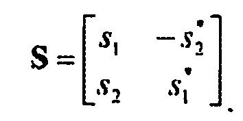
- Once the
SFBC encoding units 118 construct OFDM symbols for all subcarriers, the coded blocks are multiplexed by the S/P converters 120 and input to the eigen-beamformers 122. The eigen-beamformers 122 distribute the eigenbeams to the transmit antennas. TheIFFT units 124 convert the data in frequency domain to the data in time domain. - The
receiver 130 comprises a plurality of receive antennas (not shown), a plurality ofFFT units 132, eigen-beamformers 134,SFBC decoding units 136, acombiner 138, achannel decoder 144, achannel estimator 140, aCSI generator 142 and aCQI generator 146. - The
FFT units 132 convert the received samples to frequency domain and the eigen-beamformer 134, theSFBC decoding unit 136 and achannel decoder 144 perform the opposite operation which is performed at thetransmitter 110. Thecombiner 138 combines the SFBC decoding results using maximal ratio combining (MRC). - The
channel estimator 140 generates a channel matrix using a training sequence transmitted from the transmitter and decomposes the channel matrix into two beam-forming unitary matrices U and V, (U for transmit and V for receive), and a diagonal matrix D per sub-carrier (or per sub-carrier group) by singular value decomposition (SVD) or eigenvalue decomposition. TheCSI generator 142 generates CSI from the channel estimation results and the CQI generator generates a CQI based on the decoding results. The CSI and the CQI are sent back to thetransmitter 110. - The channel matrix H between nT transmit antennas and nR receive antennas can be written as follows:

- The channel matrix H is decomposed by SVD as follows:

where U and V are unitary matrices and D is a diagonal matrix. U ∈ CnRxnR and V ∈ CnTxnT . Then, for transmit symbol vector s, transmit precoding is simply performed as follows:
- The received signal becomes as follows:

where n is the noise introduced in the channel. The receiver completes the decomposition by using a matched filter:
- After normalizing channel gain for eigenbeams, the estimate of the transmit symbols becomes

- s is detected without having to perform successive interference cancellation or MMSE type detection D"D is a diagonal matrix that is formed by eigenvalues of H across the diagonal. Therefore, the normalization factor α = D -2. U are eigenvectors of HH H, V are eigenvectors of H H H and D is a diagonal matrix of singular values of H (square roots of eigenvalues of HH H).
-
Figure 2 is a block diagram of asystem 200 implementing open loop mode in accordance with the present invention. Thesystem 200 comprises atransmitter 210 and areceiver 230. In the open loop mode, a combination of space-frequency coding and spatial spreading in thetransmitter 210 provides diversity without requiring CSI. A variant of this scheme can be used when operating with legacy 802.11 a/g STAs. - The
transmitter 210 comprises achannel encoder 212, amultiplexer 214, apower loading unit 216, a plurality ofSFBC encoding units 218, a plurality of serial-to-parallel (S/P)converters 220, a beamformer network (BFN) 222, a plurality ofIFFT units 224 and a plurality of transmit antennas 226. As in the closed loop mode, thechannel encoder 212 uses CQI to determine coding rate and modulation per sub-carrier or group of sub-carriers. The coded data stream is multiplexed by themultiplexer 214 into two or more data streams. - In the open loop, the eigen-beamformer is replaced with the Beam Forming Network (BFN) 222. The
BFN 222 forms N beams in space, where N is the number of antennas 226. The beams are pseudo-randomly constructed by the BFN matrix operation. The independent sub-carrier groups used for the SFBC coding are transmitted on individual beams. - For legacy support, SFBC coding may not be performed. Instead diversity through beam permutation is performed which improves diversity and therefore the performance of legacy 802.11a/g equipment.
- The
receiver 230 comprises receiveantennas 231,FFT units 232, aBFN 234, an SFBC decoding and combining unit 236 and achannel decoder 238. TheFFT units 232 convert the received signal in time domain to the signal in frequency domain. The SFBC decoding and combining unit 236 decodes and combines symbols received from subcarrier groups/eigen-beams and converts them from parallel to serial using a priori-knowledge of the constellation size. Symbols are combined using MRC. Thechannel decoder 238 decodes the combined symbol and generates a CQI. - A first embodiment of power loading is explained hereinafter. The spatial processing is a combination of space-frequency coding and eigen-beamforming. This is performed to give the best compromise between the redundancy gains that SFBC affords and the spatial multiplexing that the eigen-beamformer provides. The power loading scheme operates across the eigen-modes of the channel matrix. However, SFBC also introduces the constraint that the outputs of the coder have the same power loading no matter what the input power loading is due to the cross-operation inside the coder.
-
Figure 3 is a block diagram of atransmitter 110 for depicting power loading.Figure 3 illustrates 4x4 case as an example and the first embodiment of the power loading scheme will be explained with reference to 4x4 case. However, it should be noted that the 4x4 case can be extended to any other cases. - For a particular subcarrier k, four streams of data are mapped to 2 pairs of power loading/AMC modes. In other words the modulation order is selected to be the same for each pair of inputs. This is later mapped to pairs of eigenmodes. Output of the
power loading unit 116 is applied to the dual 2x2SFBC encoding units 118 and then passed on to the eigen-beamformer 122. The eigen-beamformer 122 maps the inputs to the eigen-modes of the channel through the preprocessing. - For all k subcarriers, the eigenvalues of the channel matrix are known at the transmitter. The channel energy for each eigenmode is defined as follows:

where λ l,k is the i-th eigenvalue for the k-th subcarrier's channel. Two SNIRs are defined for two coupled eigenmodes as follows:
where M is the number of eigenmodes. In other words, the eigenmodes are grouped such that half of the eigenmodes with the largest channel energy (or SNIR) are in one group and the other half with the weakest channel energies are in the other. Therefore, the harmonic SNIRs represent the total channel energy of the stronger and weaker eigenmodes. Channel energy is an indication of how robust the eigenmodes are and hence the signal that is carried over these eigenmodes would be. This information is used to apply different adaptive modulation and coding (AMC) and/or different power loading for each half as is explained in more detail subsequently. The separation of the coupled SNIRs are defined as follows:
- During the closed loop operation the
transmitter 110 has the knowledge of current CSI from which it extracts the eigenvalues and preprocessing matrix. Thetransmitter 110 also infers the data rate that can be supported in the link, Rb, from the CSI. Then, power loading for a given, acceptable, CQI is an optimization between the number of bits that can be sent per OFDM symbol and the type of modulation that is to be used for each mode. - Using the channel energy calculated for eigenmode i as explained above, the maximum bit rate that can be supported for the channel condition is determined. Then, using the mode separation calculation above it is determined how the bit rate needs to be distributed between the two pairs of modes.
Figure 4 is a diagram of an exemplary power loading and adaptive modulation and coding mapping between two pairs of modes. In this example, the bit rate that can be supported is 24 bits per OFDM symbol for the particular sub-carrier. The lowest modulation order satisfying the bit rate is found inFigure 4 as indicated by the dashed arrow. In this example, first and second modes (first pair of coupled modes) will be using 16 QAM and third and fourth modes (second pair of coupled modes) will be using 256 QAM. - Note that this mapping is described for one CQI that is acceptable and for one subcarrier. In the case of alternative MIMO configurations, such as 2x4, 2x2, etc, the same power loading scheme is applicable except that the total number of bits in the table entries are scaled down to represent the transmit capability and that power loading can be done on a single pair of modes.
- A power loading scheme in accordance with a second embodiment is explained hereinafter. The eigenvalues per subcarrier (λ1(k) > λ2(k) > ... > λnT(k)) are ranked and eigenbeams (E1, E2, ... , EnT) are created by grouping the same ranked eigenvalues for all subcarriers as follows:

- The average of the eigenvalues per eigenbearn are computed as follows:

- The eigenbeams are paired to create Alamouti space-frequency blocks, such as {E1, E2}1, {E3, E4}2,...,{E2i-1, E2i}i ... {EnT-1, EnT}nT/2. However, if the SNR of a pair is greater than SNRmax, then the second eigenbeam of the pair is replaced with the eigenbeam with the next lower eigenvalue average until its SNR is less than or equal to SNRmin.

where
Figure 5 shows an example of pairing of subcarrier groups for power/bit loading. - A data rate for each pair of eigenbeams is determined by mapping the SNR of a pair to the data rate for a given quality. The required SNRs may be adjusted for all pairs of eigenbeams to compensate for the measurement errors and make the total transmit power be constant.
- A weight vector per pair of eigenbeams per subcarrier may be computed as follows:

where i is the i-th pair of eigenbeams, j is the j-th subcarrier. - In accordance with the third embodiment, in addition to the first or second embodiment, another power loading is applied across the sub-carriers or group of subcarriers for weak eigen-modes. In other words instead of power loading being applied to all eigenmodes it can be applied only to those that are weaker and hence can benefit from the power loading the most. In such a case, those eigenmodes that are not power loaded can still have SFBC or other coding or can have different AMC settings individually, whereas those eigenmodes that are power loaded share the same AMC setting for instance. Also, the eigenmodes of the channel are always ordered in power, from strongest to weakest. By pairing eigenmodes of similar power one may improve the power loading of the channel.
- A spatial processing scheme is configurable to any number of receive and transmit antenna combinations. Depending on the number of antennas on each side, a combination of SFBC and eigen-beamforming options are used. The table below summarizes the various configurations supported and the state of the spatial processing and power loading that is applicable to each scenario.
Table I Antenna Configuration Space Frequency (Tx X Rx) Block Code Eigen-Beamforming M beams at Tx M X N (M, N ≠ 1) M/2 block codes N beams at Rcv To be determined by re 1 X N (N≠1) not used ceiver vendor M X 1 (M≠1) M/2 block codes M beams at Tx -
- A1. A method for implementing space frequency block coding (SFBC) in an orthogonal frequency division multiplexing (OFDM) wireless communication system, the method comprising:
- performing a channel coding on input data stream;
- multiplexing the coded data stream to two or more data streams;
- obtaining channel state information (CSI);
- performing power loading based on the CSI on each of the multiplexed data streams,
- pairing subcarriers for SFBC encoding;
- performing SFBC encoding on the data streams;
- performing eigen-beamforming based on the CSI to distribute eigenbeams to a plurality of transmit antennas; and
- performing inverse fast Fourier transform (IFFT) for converting the data stream to data in time domain for transmission.
- A2. The method of embodiment A1 wherein the subcarriers are divided into a plurality of groups of subcarriers.
- A3. The method of embodiment A2 wherein bandwidth of the group of subcarriers is less than coherence bandwidth of a channel.
- A4. The method of embodiment A1 further comprising:
- calculating channel energy for each eigenmode for all subcarriers;
- calculating harmonic signal-to-noise ratios (SNRs) for a plurality of modes from the channel energy;
- calculating separation of the harmonic SNRs;
- determining a data rate that can be supported from the CSI;
- determining bit rates distributed between the modes.
- A5. The method of embodiment A4 further comprising the step of applying power optimization across each subcarrier or subcarrier group for weak eigenmodes.
- A6. The method of embodiment A1 further comprising:
- ranking the eigenvalues per subcarrier,
- generating eigenbeams by grouping the same ranked eigenvalues for all sub carriers;
- calculating average of the eigenvalues per eigenbeams;
- generating space-frequency blocks by pairing the eigenbeams; and
- determining a data rate for each pair of eigenbeams by mapping required signal-to-noise ratios (SNRs) of the pair of eigenbeams to data rates.
- A7. The method of embodiment A6 further comprising a step of adjusting the required SNRs for all pairs of eigenbeams to compensate for measurement errors and make a total transmit power be constant.
- A8. The method of embodiment A6 further comprising a step of applying a weight vector per pair of eigenbeams.
- A9. The method of embodiment A1 wherein the CSI is generated by and sent back from a receiver.
- A10. The method of embodiment A1 wherein the CSI is generated by a transmitter through channel reciprocity.
- A11. A method for implementing space frequency block coding (SFBC) in an orthogonal frequency division multiplexing (OFDM) wireless communication system, the method comprising:
- performing a channel coding on input data stream;
- multiplexing the coded data stream to two or more data streams;
- pairing subcarriers for SFBC encoding;
- performing SFBC encoding on the data streams;
- generating a plurality of beams by a beamforming network and permuting the generated beams; and
- performing inverse fast Fourier transform (IFFT) for converting the data stream to data in time domain for transmission.
- A12. An apparatus for implementing space frequency block coding (SFBC) in an orthogonal frequency division multiplexing (OFDM) wireless communication system, the apparatus comprising:
- a channel coder configured to perform a channel coding on input data stream;
- a multiplexer configured to multiplex the coded data stream in to two or more data streams;
- a power loading unit configured to perform power loading based on channel state information (CSI) on each of the multiplexed data streams;
- a plurality of SFBC encoding units configured to perform SFBC encoding on the data streams for each pair of subcarriers;
- a plurality of eigen-beamformers configured to perform eigen-beamforming based on the CSI to distribute eigenbeams to a plurality of transmit antennas;
- a plurality of inverse fast Fourier transform (IFFT) units configured to perform IFFT for converting the data stream to data in time domain for transmission; and
- a plurality of antennas.
- A13. The apparatus of embodiment A12 wherein the subcarricrs are divided into a plurality of groups of subcarriers.
- A14. The apparatus of embodiment A13 wherein bandwidth of the group of subcarriers is less than coherence bandwidth of a channel.
- A15. The apparatus of embodiment A12 wherein the power loading unit comprises:
- means for calculating channel energy for each eigenmodes for all subcarriers;
- means for calculating harmonic signal-to-noise ratios (SNRs) for a plurality of modes from the channel energy;
- means for calculating separation of the harmonic SNRs;
- means for determining a data rate that can be supported from the CSI; and
- means for determining bit rates distributed between the modes.
- A16. The apparatus of embodiment A15 wherein the power loading unit further comprises means for applying power optimization across each subcarrier or subcarrier group for weak eigenmodes.
- A17. The apparatus of embodiment A12 wherein the power loading unit comprises:
- means for ranking the eigenvalues per subcarrier;
- means for generating eigenbeam by grouping the same ranked eigenvalues for all sub carriers;
- means for calculating average of the eigenvalues per eigenbeam;
- means for generating space-frequency blocks by pairing the eigenbeams; and
- means for determining a data rate for each pair of eigenbeams by mapping required signal-to-noise ratios (SNRs) of the pair of eigenbeams to data rates.
- A18. The apparatus of embodiment A17 wherein the power loading unit further comprises a means for adjusting the required SNRs for all pairs of eigenbeams to compensate for measurement errors and make a total transmit power be constant.
- A19. The apparatus of embodiment A17 wherein the power loading unit further comprises a means for applying a weight vector per pair of eigenbeams.
- A20. The apparatus of embodiment A12 wherein the CSI is generated by and sent back from a receiver.
- A21. The apparatus of embodiment A12 wherein the CSI is generated by a transmitter through channel reciprocity.
- A22. An apparatus for implementing space frequency block coding (SFBC) in an orthogonal frequency division multiplexing (OFDM) wireless communication system, the apparatus comprising:
- a channel coder configured to perform a channel coding on input data stream;
- a multiplexer configured to multiplex the coded data stream in to two or more data streams;
- a power loading unit configured to perform power loading based on channel state information (CSI) on each of the multiplexed data streams;
- a plurality of SFBC encoding units configured to perform SFBC encoding on the data streams for each pair of subcarriers;
- a beamforming network configured to generate a plurality of beams and permuting the generated beams;
- a plurality of inverse fast Fourier transform (IFFT) units configured to perform IFFT for converting the data stream to data in time domain for transmission; and
- a plurality of antennas.
Claims (2)
- A method for transmitting data using multiple-input multiple-output MIMO space frequency block coding SFBC, and eigen-beamforming in an OFDM communication system, the method comprising:performing a channel coding on an input data stream;multiplexing the coded data stream in to least two data streams;obtaining channel state information, CSI,;ranking eigenvalues per subcarrier;creating eigenbeams by grouping the same ranked eigenvalues for all subcarriers;calculating an average eigenvalue of each of the eigenbeams;pairing eigenbeams starting from an eigenbeam with a greatest average eigenvalue such that if a signal-to-noise ratio, SNR, of a pair is greater than an SNR maximum, a second eigenbeam of the pair is replaced with an eigenbeam with the next lower average eigenvalue as far as the SNR of the pair is greater than an SNR minimum;determining a data rate for each pair of eigenbeams based on the SNR of the pair;performing SFBC encoding on the data streams with a pair of eigenbeams;performing eigen-beamforming to distribute eigenbeams to a plurality of transmit antennas; andperforming inverse Fourier transform for converting the data stream to data in time domain for transmission.
- An apparatus for transmitting data using multiple-input multiple-output , MIMO, space frequency block coding, SFBC, and eigen-beamforming in an OFDM communication system, the apparatus comprising:a channel coder configured to perform a channel coding on an input data stream;a multiplexer configured to multiplex the coded data stream in to at least two data streams;a power loading unit configured to rank eigenvalues per subcarrier, create eigenbeams by grouping the same ranked eigenvalues for all subcarriers, calculate an average eigenvalue of each of the eigenbeams, pair eigenbeams starting from an eigenbeam with a greatest average eigenvalue such that if a signal-to-noise ratio, SNR, of a pair is greater than an SNR maximum, a second eigenbeam of the pair is replaced with an eigenbeam with the next lower average eigenvalue as far as the SNR of the pair is greater than an SNR minimum, and determine a data rate for each pair of eigenbeams based on the SNR of the pair;an SFBC encoding unit configured to perform SFBC encoding on the data streams with a pair of eigenbeams;an eigen-beamforming unit configured to perform eigen-beamforming to distribute eigenbeams to a plurality of transmit antennas; and
an inverse Fourier transform unit configured to perform inverse Fourier transform for converting the data stream to data in time domain for transmission
Applications Claiming Priority (2)
| Application Number | Priority Date | Filing Date | Title |
|---|---|---|---|
| US60133804P | 2004-08-12 | 2004-08-12 | |
| EP05785474A EP1779623B1 (en) | 2004-08-12 | 2005-08-11 | Method and apparatus for implementing space frequency block coding in an orthogonal frequency division multiplexing wireless communication system |
Related Parent Applications (1)
| Application Number | Title | Priority Date | Filing Date |
|---|---|---|---|
| EP05785474.7 Division | 2005-08-11 |
Publications (2)
| Publication Number | Publication Date |
|---|---|
| EP2180647A1 EP2180647A1 (en) | 2010-04-28 |
| EP2180647B1 true EP2180647B1 (en) | 2011-10-05 |
Family
ID=35908129
Family Applications (2)
| Application Number | Title | Priority Date | Filing Date |
|---|---|---|---|
| EP05785474A Active EP1779623B1 (en) | 2004-08-12 | 2005-08-11 | Method and apparatus for implementing space frequency block coding in an orthogonal frequency division multiplexing wireless communication system |
| EP10150446A Active EP2180647B1 (en) | 2004-08-12 | 2005-08-11 | Method and apparatus for implementing space frequency block coding in an orthogonal frequency division multiplexing wireless communication system |
Family Applications Before (1)
| Application Number | Title | Priority Date | Filing Date |
|---|---|---|---|
| EP05785474A Active EP1779623B1 (en) | 2004-08-12 | 2005-08-11 | Method and apparatus for implementing space frequency block coding in an orthogonal frequency division multiplexing wireless communication system |
Country Status (20)
| Country | Link |
|---|---|
| US (7) | US7505529B2 (en) |
| EP (2) | EP1779623B1 (en) |
| JP (6) | JP2008510386A (en) |
| KR (4) | KR101282592B1 (en) |
| CN (4) | CN102664661A (en) |
| AR (3) | AR050455A1 (en) |
| AT (2) | ATE527794T1 (en) |
| AU (2) | AU2005272789B2 (en) |
| BR (1) | BRPI0515010A (en) |
| CA (2) | CA2771267C (en) |
| DE (2) | DE602005019062D1 (en) |
| DK (1) | DK1779623T3 (en) |
| ES (1) | ES2339788T3 (en) |
| HK (1) | HK1175040A1 (en) |
| IL (1) | IL181113A0 (en) |
| MX (1) | MX2007001764A (en) |
| MY (2) | MY154510A (en) |
| NO (1) | NO339219B1 (en) |
| TW (5) | TWI455535B (en) |
| WO (1) | WO2006020741A2 (en) |
Families Citing this family (96)
| Publication number | Priority date | Publication date | Assignee | Title |
|---|---|---|---|---|
| US7864659B2 (en) * | 2004-08-02 | 2011-01-04 | Interdigital Technology Corporation | Quality control scheme for multiple-input multiple-output (MIMO) orthogonal frequency division multiplexing (OFDM) systems |
| JP4744965B2 (en) * | 2004-08-09 | 2011-08-10 | パナソニック株式会社 | Wireless communication device |
| GB2419786C (en) * | 2004-10-27 | 2009-10-07 | Toshiba Res Europ Ltd | Multiple list link adaption |
| KR100909539B1 (en) * | 2004-11-09 | 2009-07-27 | 삼성전자주식회사 | Apparatus and method for supporting various multi-antenna technologies in a broadband wireless access system using multiple antennas |
| US8130855B2 (en) | 2004-11-12 | 2012-03-06 | Interdigital Technology Corporation | Method and apparatus for combining space-frequency block coding, spatial multiplexing and beamforming in a MIMO-OFDM system |
| CN1780278A (en) * | 2004-11-19 | 2006-05-31 | 松下电器产业株式会社 | Self adaptable modification and encode method and apparatus in sub-carrier communication system |
| US7649861B2 (en) * | 2004-11-30 | 2010-01-19 | Intel Corporation | Multiple antenna multicarrier communication system and method with reduced mobile-station processing |
| US7822128B2 (en) * | 2004-12-03 | 2010-10-26 | Intel Corporation | Multiple antenna multicarrier transmitter and method for adaptive beamforming with transmit-power normalization |
| KR100782925B1 (en) * | 2004-12-15 | 2007-12-07 | 삼성전자주식회사 | Multiple Antenna Telecommunication System |
| JP4746420B2 (en) * | 2004-12-27 | 2011-08-10 | 株式会社東芝 | Wireless communication apparatus and method |
| US7602855B2 (en) * | 2005-04-01 | 2009-10-13 | Interdigital Technology Corporation | Method and apparatus for singular value decomposition of a channel matrix |
| CA2627401C (en) | 2005-10-27 | 2015-05-05 | Qualcomm Incorporated | Precoding for segment sensitive scheduling in wireless communication systems |
| US8594207B2 (en) | 2005-10-31 | 2013-11-26 | Motorola Mobility Llc | Method and apparatus for providing channel quality feedback in an orthogonal frequency division multiplexing communication system |
| KR100705448B1 (en) * | 2005-12-09 | 2007-04-09 | 한국전자통신연구원 | Method and system for allocation of transmission power using channel information of code-book in ofdm with multiple transmission antennas |
| US7609774B2 (en) * | 2005-12-20 | 2009-10-27 | Samsung Electronics Co., Ltd. | Beamforming transceiver architecture with enhanced channel estimation and frequency offset estimation capabilities in high throughput WLAN systems |
| US7715803B2 (en) * | 2005-12-20 | 2010-05-11 | Samsung Electronics Co., Ltd. | Methods and apparatus for constant-power loading asymmetric antenna configuration |
| US7697621B2 (en) * | 2005-12-22 | 2010-04-13 | Samsung Electronics Co., Ltd. | Method and system for power loading implementation detection in beamforming systems |
| US20070153934A1 (en) * | 2005-12-29 | 2007-07-05 | Samsung Electronics Co., Ltd. | Constant uneven power loading in beamforming systems for high throughput wireless communications |
| EP1821444B1 (en) * | 2006-02-21 | 2018-09-19 | Samsung Electronics Co., Ltd. | Apparatus and method for transmission and reception in a multi-user MIMO communication system |
| JP4753750B2 (en) * | 2006-03-06 | 2011-08-24 | 株式会社日立製作所 | Wireless communication system and wireless base station apparatus |
| KR100925733B1 (en) * | 2006-04-21 | 2009-11-11 | 엘지전자 주식회사 | Method for transmitting information in wireless communication system and terminal supporting the method |
| CN101783698A (en) * | 2006-05-30 | 2010-07-21 | 交互数字技术公司 | Method and apparatus for scaling a signal for improving performance of a receiver in a mimo system |
| KR101274871B1 (en) * | 2006-06-14 | 2013-06-17 | 삼성전자주식회사 | Method and apparatus for transceiving data in a multi antenna system of closed loop scheme |
| US8107552B2 (en) | 2006-06-28 | 2012-01-31 | Samsung Electronics Co., Ltd. | System and method of wireless communication of uncompressed video having a fast fourier transform-based channel interleaver |
| US8189627B2 (en) | 2006-06-28 | 2012-05-29 | Samsung & Electronics Co., Ltd. | System and method for digital communications using multiple parallel encoders |
| US8234552B2 (en) * | 2007-11-06 | 2012-07-31 | Qualcomm Incorporated | Method and apparatus for preamble creation and communication in a wireless communication network |
| KR101484464B1 (en) | 2006-08-21 | 2015-01-20 | 코닌클리케 필립스 엔.브이. | Efficient cqi signaling in multi-beam mimo systems |
| US7944985B2 (en) * | 2006-08-24 | 2011-05-17 | Interdigital Technology Corporation | MIMO transmitter and receiver for supporting downlink communication of single channel codewords |
| DK2060021T3 (en) | 2006-08-28 | 2019-07-01 | Koninklijke Philips Nv | EFFICIENT CQI SIGNALING IN MIMO SYSTEMS WITH VARIABLE NUMBER OF RAYS |
| US8374650B2 (en) * | 2006-09-27 | 2013-02-12 | Apple, Inc. | Methods for optimal collaborative MIMO-SDMA |
| US8626104B2 (en) | 2006-09-28 | 2014-01-07 | Apple Inc. | Generalized codebook design method for limited feedback systems |
| KR100800668B1 (en) * | 2006-09-29 | 2008-02-01 | 삼성전자주식회사 | Channel estimation method and apparutus in a ofdm wireless communication system |
| EP2067332A4 (en) * | 2006-09-29 | 2014-03-26 | Samsung Electronics Co Ltd | Channel estimation method and apparatus in an ofdm wireless communication system |
| US7702029B2 (en) | 2006-10-02 | 2010-04-20 | Freescale Semiconductor, Inc. | MIMO precoding enabling spatial multiplexing, power allocation and adaptive modulation and coding |
| US8194750B2 (en) * | 2006-10-16 | 2012-06-05 | Samsung Electronics Co., Ltd. | System and method for digital communication having a circulant bit interleaver for equal error protection (EEP) and unequal error protection (UEP) |
| TW200822603A (en) * | 2006-10-31 | 2008-05-16 | Interdigital Tech Corp | Transmit diversity of broadcast channel in OFDMA based evolved UTRA |
| US20080101494A1 (en) * | 2006-10-31 | 2008-05-01 | Freescale Semiconductor, Inc. | System and method for generating MIMO signals |
| WO2008069579A1 (en) * | 2006-12-05 | 2008-06-12 | Electronics And Telecommunications Research Institute | Method for transmitting signal and information on antenna, and method for estimating the number of antennas |
| US8073069B2 (en) * | 2007-01-05 | 2011-12-06 | Apple Inc. | Multi-user MIMO-SDMA for finite rate feedback systems |
| US8111670B2 (en) | 2007-03-12 | 2012-02-07 | Samsung Electronics Co., Ltd. | System and method for processing wireless high definition video data using remainder bytes |
| US7809074B2 (en) * | 2007-03-16 | 2010-10-05 | Freescale Semiconductor, Inc. | Generalized reference signaling scheme for multi-user, multiple input, multiple output (MU-MIMO) using arbitrarily precoded reference signals |
| US8020075B2 (en) | 2007-03-16 | 2011-09-13 | Apple Inc. | Channel quality index feedback reduction for broadband systems |
| US7961807B2 (en) * | 2007-03-16 | 2011-06-14 | Freescale Semiconductor, Inc. | Reference signaling scheme using compressed feedforward codebooks for multi-user, multiple input, multiple output (MU-MIMO) systems |
| US8831116B2 (en) | 2007-03-20 | 2014-09-09 | Motorola Mobility Llc | Method and apparatus for providing channel quality and precoding metric feedback in an orthogonal frequency division multiplexing communication system |
| US8130864B1 (en) * | 2007-04-03 | 2012-03-06 | Marvell International Ltd. | System and method of beamforming with reduced feedback |
| KR20080090707A (en) * | 2007-04-05 | 2008-10-09 | 엘지전자 주식회사 | Method for signal transmitting and apparatus for the same, method for signal receiving and apparatus for the same |
| US7843990B2 (en) * | 2007-04-09 | 2010-11-30 | Alcatel-Lucent Usa Inc. | Determining a channel matrix by measuring interference |
| US8547986B2 (en) * | 2007-04-30 | 2013-10-01 | Apple Inc. | System and method for resource block-specific control signaling |
| KR101365565B1 (en) * | 2007-08-08 | 2014-02-21 | 포항공과대학교 산학협력단 | Space frequency block code signal processing system |
| EP3293905B1 (en) | 2007-08-14 | 2021-02-17 | LG Electronics Inc. | Method for acquiring resource region information for phich |
| KR101455981B1 (en) * | 2007-08-14 | 2014-11-03 | 엘지전자 주식회사 | Method For Adaptively Generating Channel Quality Indicator According To The Downlink Status, And User Equipment For The Same |
| US8098755B2 (en) * | 2007-09-07 | 2012-01-17 | Broadcom Corporation | Method and system for beamforming in a multiple user multiple input multiple output (MIMO) communication system using a codebook |
| KR101358991B1 (en) * | 2007-09-14 | 2014-02-06 | 삼성전자주식회사 | Method and apparatus for multiple beamforming |
| US7916081B2 (en) * | 2007-12-19 | 2011-03-29 | Qualcomm Incorporated | Beamforming in MIMO systems |
| US8081110B2 (en) * | 2007-11-06 | 2011-12-20 | Qualcomm Incorporated | Association in contention access period |
| US8054223B2 (en) * | 2007-11-06 | 2011-11-08 | Qualcomm Incorporated | Quasi-omni training in channel time allocation period |
| GB2458324B (en) * | 2008-03-14 | 2010-12-08 | Toshiba Res Europ Ltd | Wireless communications apparatus |
| US7978623B1 (en) | 2008-03-22 | 2011-07-12 | Freescale Semiconductor, Inc. | Channel rank updates in multiple-input multiple-output communication systems |
| WO2009125591A1 (en) * | 2008-04-09 | 2009-10-15 | パナソニック株式会社 | Wireless receiver, wireless transmitter, and feedback method |
| US8320492B2 (en) * | 2008-07-07 | 2012-11-27 | Wi-Lan Inc. | Closed form singular value decomposition |
| EP2169888A1 (en) * | 2008-09-30 | 2010-03-31 | NTT DoCoMo Inc. | A three dimensional pilot aided radio channel estimator |
| CN101944978B (en) * | 2009-07-03 | 2013-01-16 | 中兴通讯股份有限公司 | Data demodulation method and device based on downlink emission diversity mode of LTE (Long Term Evolution) system |
| US8861629B2 (en) * | 2009-07-31 | 2014-10-14 | Cisco Technology, Inc. | Power allocation of spatial streams in MIMO wireless communication system |
| US8295335B2 (en) | 2009-12-31 | 2012-10-23 | Intel Corporation | Techniques to control uplink power |
| KR101567018B1 (en) * | 2010-02-09 | 2015-11-06 | 삼성전자주식회사 | System for determining mimo/dsm operating mode based on network backhaul link environment and cooperation level between base stations |
| EP2553823B1 (en) * | 2010-04-01 | 2014-06-04 | Telefonaktiebolaget LM Ericsson (publ) | Precoder codebooks for effective channels with structured frequency-selectivity |
| US8422543B2 (en) * | 2010-05-28 | 2013-04-16 | Echostar Technologies L.L.C. | Apparatus, systems and methods of signal compensation for different signals communicated over a coaxial cable system |
| KR101462427B1 (en) * | 2010-11-10 | 2014-11-17 | 서울대학교산학협력단 | System and method for delivering information in sound wave communication based on preserving of audio signal, and apparatus applied to the same |
| KR101967252B1 (en) * | 2010-12-10 | 2019-04-10 | 선 페이턴트 트러스트 | Transmitting device |
| US9288691B2 (en) * | 2011-01-24 | 2016-03-15 | Lg Electronics Inc. | Method for reporting channel state information in wireless communication system and apparatus therefor |
| JP5777092B2 (en) * | 2011-06-10 | 2015-09-09 | ソフトバンク株式会社 | Wireless communication device, wireless transmission system, and wireless transmission method |
| US8553800B1 (en) * | 2012-05-09 | 2013-10-08 | Metanoia Communications Inc. | LTE-advanced transmit diversity decoders |
| US9461855B2 (en) * | 2012-07-05 | 2016-10-04 | Intel Corporation | Methods and arrangements for selecting channel updates in wireless networks |
| US9215622B1 (en) * | 2012-07-30 | 2015-12-15 | GoNet Systems Ltd. | Method and systems for associating wireless transmission with directions-of-arrival thereof |
| US9673881B2 (en) * | 2012-10-10 | 2017-06-06 | Sharp Kabushiki Kaisha | Terminal device, base station device, wireless communication system, reception method, and integrated circuit |
| US8842764B2 (en) * | 2012-12-14 | 2014-09-23 | Telefonaktiebolaget L M Ericsson (Publ) | Precoder weight selection for MIMO communications when multiplicative noise limited |
| US8831127B2 (en) | 2012-12-14 | 2014-09-09 | Telefonaktiebolaget L M Ericsson (Publ) | Antenna reconfiguration for MIMO communications when multiplicative noise limited |
| US8891657B2 (en) | 2012-12-14 | 2014-11-18 | Telefonaktiebolaget L M Ericsson(Publ) | Transmission power distribution for MIMO communications when multiplicative noise limited |
| GB2514174B (en) * | 2013-05-17 | 2015-12-02 | Cambium Networks Ltd | Improvements to adaptive modulation |
| KR101486148B1 (en) * | 2013-07-10 | 2015-01-26 | 포항공과대학교 산학협력단 | Method for cancelling inter-subcarrier interference in wireless communication systems and apparatus for performing the same |
| WO2015038141A1 (en) * | 2013-09-13 | 2015-03-19 | Hewlett-Packard Development Company, L.P. | Subcarrier power reallocation |
| EP3114568A4 (en) | 2014-03-07 | 2017-10-18 | Trustees of Boston University | System and method for embedding phase and amplitude into a real-valued unipolar signal |
| JP2015201804A (en) * | 2014-04-10 | 2015-11-12 | 富士通株式会社 | Receiver, reception method, transmitter, transmission method, and radio communication system |
| US9860099B1 (en) * | 2015-02-18 | 2018-01-02 | Newracom, Inc. | Support of frequency diversity mode for block code based transmission in OFDMA |
| JP6679830B2 (en) * | 2015-03-11 | 2020-04-15 | 日本電気株式会社 | Receiving device and receiving method |
| US10103799B2 (en) * | 2015-03-16 | 2018-10-16 | Lockheed Martin Corporation | Apparatus and method for increased data rates in underwater communications using orbital angular momentum |
| WO2016156765A1 (en) * | 2015-03-30 | 2016-10-06 | Toshiba Research Europe Limited | Wireless communication methods and apparatus |
| US9509381B1 (en) * | 2015-09-18 | 2016-11-29 | Samsung Electronics Co., Ltd | Apparatus and method of blind detection of interference rank information in wireless communication system |
| US9876552B2 (en) | 2016-02-01 | 2018-01-23 | Qualcomm Incorporated | Beamforming techniques for single-stream communications |
| WO2017134273A1 (en) * | 2016-02-05 | 2017-08-10 | Sony Corporation | Terminal device, infrastructure equipment, methods and integratedid50000076049732 ro/101 2017-02-08 circuitry |
| TWI634768B (en) * | 2016-10-05 | 2018-09-01 | 國立中山大學 | Space frequency block code orthogonal frequency division multiplexing system |
| CN112788767B (en) * | 2016-12-19 | 2023-06-02 | 华为技术有限公司 | Transmission method, base station and terminal for dynamically adjusting beam set |
| CN109565754B (en) * | 2016-12-29 | 2021-02-23 | 华为技术有限公司 | Coding method and device |
| CN110235384B (en) | 2017-01-06 | 2022-02-08 | 天工方案公司 | Harmonic beamforming |
| US9942020B1 (en) * | 2017-04-26 | 2018-04-10 | Cisco Technology, Inc. | Minimum delay spatio-temporal filtering for interference rejection |
| CN111108706B (en) * | 2017-09-28 | 2021-09-21 | 华为技术有限公司 | Apparatus and method for compressing and/or decompressing channel state information |
Family Cites Families (101)
| Publication number | Priority date | Publication date | Assignee | Title |
|---|---|---|---|---|
| US5666378A (en) | 1994-03-18 | 1997-09-09 | Glenayre Electronics, Inc. | High performance modem using pilot symbols for equalization and frame synchronization |
| CA2302289C (en) * | 1996-08-29 | 2005-11-08 | Gregory G. Raleigh | Spatio-temporal processing for communication |
| DE19909243C1 (en) | 1999-02-22 | 2000-11-23 | Siemens Ag | Method for transmitting a control signal to a vehicle and a receiving device for receiving the control signal |
| US6594473B1 (en) * | 1999-05-28 | 2003-07-15 | Texas Instruments Incorporated | Wireless system with transmitter having multiple transmit antennas and combining open loop and closed loop transmit diversities |
| US7004936B2 (en) | 2000-08-09 | 2006-02-28 | Cryocor, Inc. | Refrigeration source for a cryoablation catheter |
| US6067290A (en) * | 1999-07-30 | 2000-05-23 | Gigabit Wireless, Inc. | Spatial multiplexing in a cellular network |
| US6351499B1 (en) * | 1999-12-15 | 2002-02-26 | Iospan Wireless, Inc. | Method and wireless systems using multiple antennas and adaptive control for maximizing a communication parameter |
| US6519279B1 (en) * | 2000-01-05 | 2003-02-11 | Motorola, Inc. | Transceiver circuitry, portable communication device and method for performing radio communication |
| US7149253B2 (en) * | 2000-03-21 | 2006-12-12 | Texas Instruments Incorporated | Wireless communication |
| US6473467B1 (en) | 2000-03-22 | 2002-10-29 | Qualcomm Incorporated | Method and apparatus for measuring reporting channel state information in a high efficiency, high performance communications system |
| US6493331B1 (en) | 2000-03-30 | 2002-12-10 | Qualcomm Incorporated | Method and apparatus for controlling transmissions of a communications systems |
| US7139324B1 (en) * | 2000-06-02 | 2006-11-21 | Nokia Networks Oy | Closed loop feedback system for improved down link performance |
| US6452546B1 (en) | 2000-06-14 | 2002-09-17 | Hrl Laboratories, Llc | Wavelength division multiplexing methods and apparatus for constructing photonic beamforming networks |
| ES2701182T3 (en) | 2000-07-12 | 2019-02-21 | Qualcomm Inc | Procedure and apparatus to generate pilot signals in a MIMO system |
| CA2415632C (en) | 2000-07-14 | 2011-12-13 | At&T Wireless Services, Inc. | Adaptive dual-polarization communication of orthogonal frequency division multiplexed signals |
| US6985434B2 (en) * | 2000-09-01 | 2006-01-10 | Nortel Networks Limited | Adaptive time diversity and spatial diversity for OFDM |
| EP2259480A3 (en) * | 2000-11-20 | 2012-05-02 | Sony Deutschland Gmbh | Adaptive subcarrier loading |
| CN100456758C (en) * | 2000-12-15 | 2009-01-28 | 昂达博思公司 | Multi-carrier communications with group-based subcarrier allocation |
| EP1241824A1 (en) | 2001-03-14 | 2002-09-18 | TELEFONAKTIEBOLAGET LM ERICSSON (publ) | Multiplexing method in a multicarrier transmit diversity system |
| US6771706B2 (en) | 2001-03-23 | 2004-08-03 | Qualcomm Incorporated | Method and apparatus for utilizing channel state information in a wireless communication system |
| US6859503B2 (en) * | 2001-04-07 | 2005-02-22 | Motorola, Inc. | Method and system in a transceiver for controlling a multiple-input, multiple-output communications channel |
| KR100510434B1 (en) * | 2001-04-09 | 2005-08-26 | 니폰덴신뎅와 가부시키가이샤 | OFDM signal transmission system, OFDM signal transmission apparatus and OFDM signal receiver |
| EP1255369A1 (en) * | 2001-05-04 | 2002-11-06 | TELEFONAKTIEBOLAGET LM ERICSSON (publ) | Link adaptation for wireless MIMO transmission schemes |
| US7688899B2 (en) * | 2001-05-17 | 2010-03-30 | Qualcomm Incorporated | Method and apparatus for processing data for transmission in a multi-channel communication system using selective channel inversion |
| JP4387791B2 (en) * | 2001-05-25 | 2009-12-24 | リージェンツ オブ ザ ユニバーシティ オブ ミネソタ | Space-time coded transmission method in a wireless communication network |
| FR2825448B1 (en) | 2001-05-30 | 2003-09-12 | Inst Francais Du Petrole | THERMAL GENERATOR FOR LIMITING EMISSIONS OF NITROGEN OXIDES BY RECOMBUSTION OF FUMES AND METHOD FOR IMPLEMENTING SUCH A GENERATOR |
| JP2003018127A (en) * | 2001-07-03 | 2003-01-17 | Fujitsu Ltd | Transmitter and receiver |
| KR100747524B1 (en) | 2001-07-07 | 2007-08-08 | 엘지전자 주식회사 | Method for controlling signal power in variable data rate mode |
| EP1282245A1 (en) | 2001-07-30 | 2003-02-05 | Telefonaktiebolaget L M Ericsson (Publ) | Channel estimation in a multi carrier transmit diversity system |
| EP1283614A1 (en) | 2001-08-10 | 2003-02-12 | TELEFONAKTIEBOLAGET L M ERICSSON (publ) | Channel estimation in a multicarrier transmit diversity system |
| EP1284545B1 (en) * | 2001-08-13 | 2008-07-02 | Motorola, Inc. | Transmit diversity wireless communication |
| US20030043071A1 (en) * | 2001-08-27 | 2003-03-06 | E-Tenna Corporation | Electro-mechanical scanned array system and method |
| CA2407242C (en) | 2001-10-10 | 2011-05-31 | David I. Havelock | Aggregate beamformer for use in a directional receiving array |
| JP3607238B2 (en) | 2001-10-22 | 2005-01-05 | 株式会社東芝 | OFDM signal receiving system |
| JP3875086B2 (en) | 2001-11-30 | 2007-01-31 | ソフトバンクテレコム株式会社 | Orthogonal frequency division multiplexing system and transmitter / receiver |
| US7154936B2 (en) | 2001-12-03 | 2006-12-26 | Qualcomm, Incorporated | Iterative detection and decoding for a MIMO-OFDM system |
| US6760388B2 (en) * | 2001-12-07 | 2004-07-06 | Qualcomm Incorporated | Time-domain transmit and receive processing with channel eigen-mode decomposition for MIMO systems |
| DE10162546A1 (en) | 2001-12-19 | 2003-07-10 | Siemens Ag | Device for sending/receiving data signals using several transmission modes has memory for storing association table that associates set of modulation types with each transmission mode |
| DE10162548A1 (en) | 2001-12-19 | 2003-07-17 | Siemens Ag | Combination of adaptive modulation and space frequency block coding or antenna weighting for efficient encoded data transmission |
| EP1775873A3 (en) * | 2002-01-04 | 2012-12-26 | Nokia Corporation | Reception of signals in a high rate transmission diversity system |
| US6980614B2 (en) | 2002-01-14 | 2005-12-27 | Raytheon Company | System and method for subband beamforming using adaptive weight normalization |
| US7499709B2 (en) * | 2002-02-07 | 2009-03-03 | Alcatel-Lucent Usa Inc. | Method and apparatus for closed loop transmit diversity in a wireless communications system |
| US7116944B2 (en) * | 2002-02-07 | 2006-10-03 | Lucent Technologies Inc. | Method and apparatus for feedback error detection in a wireless communications systems |
| US7298717B2 (en) * | 2002-02-15 | 2007-11-20 | Texas Instruments Incorporated | Method and apparatus for providing transmit diversity with adaptive basis |
| US6862271B2 (en) * | 2002-02-26 | 2005-03-01 | Qualcomm Incorporated | Multiple-input, multiple-output (MIMO) systems with multiple transmission modes |
| US7197084B2 (en) * | 2002-03-27 | 2007-03-27 | Qualcomm Incorporated | Precoding for a multipath channel in a MIMO system |
| TW522639B (en) * | 2002-03-28 | 2003-03-01 | Accton Technology Corp | Orthogonally-multiplexed orthogonal amplitude modulation method and device |
| US7103325B1 (en) * | 2002-04-05 | 2006-09-05 | Nortel Networks Limited | Adaptive modulation and coding |
| US7522673B2 (en) * | 2002-04-22 | 2009-04-21 | Regents Of The University Of Minnesota | Space-time coding using estimated channel information |
| JP4125913B2 (en) * | 2002-05-24 | 2008-07-30 | 松下電器産業株式会社 | Wireless transmission device, wireless reception device, and wireless communication system |
| JP4140816B2 (en) | 2002-05-24 | 2008-08-27 | 富士通株式会社 | Micro mirror element |
| US7327800B2 (en) * | 2002-05-24 | 2008-02-05 | Vecima Networks Inc. | System and method for data detection in wireless communication systems |
| EP1367760B1 (en) * | 2002-05-27 | 2009-11-18 | Nokia Corporation | Transmit/receive diversity wireless communication |
| US7181246B2 (en) * | 2002-06-05 | 2007-02-20 | Neocific, Inc. | Adaptive communications system and method |
| KR100498326B1 (en) | 2002-06-18 | 2005-07-01 | 엘지전자 주식회사 | Adaptive modulation coding apparatus and method for mobile communication device |
| TW567696B (en) | 2002-07-19 | 2003-12-21 | Silicon Integrated Sys Corp | Channel estimator for WLAN |
| JP2004064108A (en) * | 2002-07-24 | 2004-02-26 | Natl Univ Of Singapore | Wireless communication apparatus and method |
| US20040032910A1 (en) * | 2002-08-13 | 2004-02-19 | Jyhchau Horng | MIMO systems with STTD encoding and dynamic power allocation |
| US6940917B2 (en) * | 2002-08-27 | 2005-09-06 | Qualcomm, Incorporated | Beam-steering and beam-forming for wideband MIMO/MISO systems |
| EP1408623B1 (en) | 2002-10-10 | 2010-12-15 | Samsung Electronics Co., Ltd. | Transmitting and receiving apparatus for supporting transmit antenna diversity using space-time block code. |
| KR100630108B1 (en) * | 2002-10-10 | 2006-09-27 | 삼성전자주식회사 | Transmitting and receiving apparatus for supporting transmission antenna diversity using space-time block code |
| US20040121730A1 (en) * | 2002-10-16 | 2004-06-24 | Tamer Kadous | Transmission scheme for multi-carrier MIMO systems |
| US7002900B2 (en) | 2002-10-25 | 2006-02-21 | Qualcomm Incorporated | Transmit diversity processing for a multi-antenna communication system |
| US8320301B2 (en) | 2002-10-25 | 2012-11-27 | Qualcomm Incorporated | MIMO WLAN system |
| US8218609B2 (en) * | 2002-10-25 | 2012-07-10 | Qualcomm Incorporated | Closed-loop rate control for a multi-channel communication system |
| AU2003280627A1 (en) | 2002-11-01 | 2004-05-25 | Matsushita Electric Industrial Co., Ltd. | Multi-carrier communication method and multi-carrier communication method |
| JP4291669B2 (en) * | 2002-11-01 | 2009-07-08 | パナソニック株式会社 | Multi-carrier communication apparatus and multi-carrier communication method |
| JP4091827B2 (en) * | 2002-11-26 | 2008-05-28 | 松下電器産業株式会社 | Wireless transmission device and wireless reception device |
| KR100511559B1 (en) | 2002-11-28 | 2005-08-31 | 한국전자통신연구원 | Transmitting and Receiving Method having Distortion Reduction Caused by a Time-varying Channel in an Orthogonal Frequency Division Multiplex System |
| KR100494844B1 (en) * | 2002-12-21 | 2005-06-14 | 한국전자통신연구원 | Method for Adaptive Resource Allocation for Communication System |
| JP4163941B2 (en) | 2002-12-24 | 2008-10-08 | 松下電器産業株式会社 | Wireless transmission apparatus and wireless transmission method |
| JP4256158B2 (en) * | 2002-12-26 | 2009-04-22 | パナソニック株式会社 | Wireless communication apparatus and wireless communication method |
| KR100552669B1 (en) * | 2002-12-26 | 2006-02-20 | 한국전자통신연구원 | Adaptive Modulation Method for MIMO System using Layered Time-Space detector |
| US7813440B2 (en) * | 2003-01-31 | 2010-10-12 | Ntt Docomo, Inc. | Multiple-output multiple-input (MIMO) communication system, MIMO receiver and MIMO receiving method |
| US7782970B2 (en) * | 2003-02-27 | 2010-08-24 | Intel Corporation | Apparatus and associated methods to introduce diversity in a multicarrier communication channel |
| US7983355B2 (en) * | 2003-07-09 | 2011-07-19 | Broadcom Corporation | System and method for RF signal combining and adaptive bit loading for data rate maximization in multi-antenna communication systems |
| US20040192218A1 (en) * | 2003-03-31 | 2004-09-30 | Oprea Alexandru M. | System and method for channel data transmission in wireless communication systems |
| KR100591890B1 (en) * | 2003-04-01 | 2006-06-20 | 한국전자통신연구원 | Method for adaptive transmission and receiving in a wireless communication system with multiple antennas |
| CA2427403C (en) * | 2003-04-21 | 2008-10-28 | Regents Of The University Of Minnesota | Space-time-frequency coded ofdm over frequency-selective fading channels |
| FI20031079A0 (en) * | 2003-07-16 | 2003-07-16 | Nokia Corp | A method for controlling communication resources, and a controller |
| KR100731824B1 (en) * | 2003-07-16 | 2007-06-25 | 노키아 코포레이션 | Method, controller and computer-readable medium for controlling communication resources |
| US20050047517A1 (en) | 2003-09-03 | 2005-03-03 | Georgios Giannakis B. | Adaptive modulation for multi-antenna transmissions with partial channel knowledge |
| WO2005029758A2 (en) * | 2003-09-15 | 2005-03-31 | Intel Corporation | Multiple antenna systems and methods using high-throughput space-frequency block codes |
| US7440510B2 (en) * | 2003-09-15 | 2008-10-21 | Intel Corporation | Multicarrier transmitter, multicarrier receiver, and methods for communicating multiple spatial signal streams |
| CN1849769B (en) | 2003-09-15 | 2010-06-16 | 英特尔公司 | Multiple antenna systems and methods using high-throughput space-frequency block codes |
| US7315577B2 (en) * | 2003-09-15 | 2008-01-01 | Intel Corporation | Multiple antenna systems and method using high-throughput space-frequency block codes |
| GB2416465A (en) * | 2004-05-12 | 2006-01-25 | Toshiba Res Europ Ltd | Transmitting a signal using Alamouti encoding and receiving the signal using ordered successive interference cancellation (OSIC) |
| US7724835B2 (en) | 2004-05-17 | 2010-05-25 | Qualcomm Incorporated | Space-time block coding in orthogonal frequency division communication systems |
| WO2005125020A1 (en) * | 2004-06-22 | 2005-12-29 | Nortel Networks Limited | Methods and systems for enabling feedback in wireless communication networks |
| US7570696B2 (en) * | 2004-06-25 | 2009-08-04 | Intel Corporation | Multiple input multiple output multicarrier communication system and methods with quantized beamforming feedback |
| CN102264160B (en) * | 2004-08-11 | 2015-01-14 | 松下电器产业株式会社 | Base Station Device and Transmission Signal Forming Method |
| US8130855B2 (en) | 2004-11-12 | 2012-03-06 | Interdigital Technology Corporation | Method and apparatus for combining space-frequency block coding, spatial multiplexing and beamforming in a MIMO-OFDM system |
| US7599419B2 (en) * | 2005-01-14 | 2009-10-06 | The Regents Of The University Of California | Method and apparatus for use of space time trellis codes based on channel phase feedback |
| US20060173977A1 (en) * | 2005-02-03 | 2006-08-03 | Next Generation Broadband | A process for dynamic user control on always-on ip network |
| KR100662184B1 (en) * | 2005-07-22 | 2006-12-27 | 제일모직주식회사 | Halogen-free flameproof thermoplastic resin composition |
| US7548730B2 (en) * | 2006-03-16 | 2009-06-16 | Intel Corporation | Systems and methods for improving performance of multiple spatial communication channels |
| US7944985B2 (en) * | 2006-08-24 | 2011-05-17 | Interdigital Technology Corporation | MIMO transmitter and receiver for supporting downlink communication of single channel codewords |
| US7715485B1 (en) * | 2007-01-08 | 2010-05-11 | L-3 Communications, Corp. | MIMO communication using interference cancellation and unequal transmit power distribution |
| US8254429B1 (en) * | 2007-10-02 | 2012-08-28 | Apple Inc. | Communication systems and methods |
| US7826853B2 (en) * | 2007-11-02 | 2010-11-02 | Mitsubishi Electric Research Laboratories, Inc. | Cooperative base stations in wireless networks |
| KR100925440B1 (en) * | 2008-01-28 | 2009-11-06 | 엘지전자 주식회사 | Method for allocating physical hybrid ARQ indicator channel |
-
2005
- 2005-08-11 MY MYPI20090274A patent/MY154510A/en unknown
- 2005-08-11 CN CN2012101249440A patent/CN102664661A/en active Pending
- 2005-08-11 TW TW094127401A patent/TWI455535B/en active
- 2005-08-11 AU AU2005272789A patent/AU2005272789B2/en not_active Ceased
- 2005-08-11 TW TW102102720A patent/TWI543572B/en active
- 2005-08-11 WO PCT/US2005/028487 patent/WO2006020741A2/en active Application Filing
- 2005-08-11 ES ES05785474T patent/ES2339788T3/en active Active
- 2005-08-11 AT AT10150446T patent/ATE527794T1/en not_active IP Right Cessation
- 2005-08-11 EP EP05785474A patent/EP1779623B1/en active Active
- 2005-08-11 CA CA2771267A patent/CA2771267C/en not_active Expired - Fee Related
- 2005-08-11 AT AT05785474T patent/ATE456232T1/en not_active IP Right Cessation
- 2005-08-11 DK DK05785474.7T patent/DK1779623T3/en active
- 2005-08-11 BR BRPI0515010-8A patent/BRPI0515010A/en not_active Application Discontinuation
- 2005-08-11 CN CN201210124013.0A patent/CN102638298B/en active Active
- 2005-08-11 MX MX2007001764A patent/MX2007001764A/en active IP Right Grant
- 2005-08-11 CN CNA2005800273883A patent/CN101002447A/en active Pending
- 2005-08-11 MY MYPI20053749A patent/MY143899A/en unknown
- 2005-08-11 TW TW101121628A patent/TWI517638B/en active
- 2005-08-11 JP JP2007525777A patent/JP2008510386A/en not_active Ceased
- 2005-08-11 CA CA002576842A patent/CA2576842A1/en not_active Abandoned
- 2005-08-11 TW TW095104280A patent/TWI379560B/en active
- 2005-08-11 TW TW094213763U patent/TWM287552U/en not_active IP Right Cessation
- 2005-08-11 DE DE602005019062T patent/DE602005019062D1/en active Active
- 2005-08-11 US US11/201,695 patent/US7505529B2/en not_active Expired - Fee Related
- 2005-08-11 EP EP10150446A patent/EP2180647B1/en active Active
- 2005-08-12 KR KR1020050074255A patent/KR101282592B1/en active IP Right Grant
- 2005-08-12 DE DE202005012766U patent/DE202005012766U1/en not_active Expired - Lifetime
- 2005-08-12 AR ARP050103396A patent/AR050455A1/en not_active Application Discontinuation
- 2005-08-12 CN CNU2005201051492U patent/CN200973110Y/en not_active Expired - Lifetime
-
2007
- 2007-02-01 IL IL181113A patent/IL181113A0/en unknown
- 2007-03-12 NO NO20071317A patent/NO339219B1/en not_active IP Right Cessation
- 2007-10-10 HK HK13101882.4A patent/HK1175040A1/en not_active IP Right Cessation
-
2008
- 2008-04-29 AR ARP080101805A patent/AR066342A2/en not_active Application Discontinuation
-
2009
- 2009-01-27 US US12/360,351 patent/US8532210B2/en active Active
- 2009-04-03 AU AU2009201306A patent/AU2009201306B8/en not_active Ceased
-
2010
- 2010-04-14 AR ARP100101243A patent/AR076294A2/en active IP Right Grant
-
2011
- 2011-10-03 JP JP2011219396A patent/JP2012070382A/en active Pending
-
2012
- 2012-02-21 KR KR1020120017688A patent/KR101314423B1/en active IP Right Grant
- 2012-09-12 KR KR1020120101169A patent/KR101251931B1/en active IP Right Grant
- 2012-10-22 JP JP2012232993A patent/JP2013048468A/en active Pending
-
2013
- 2013-03-27 KR KR1020130032844A patent/KR20130053423A/en active IP Right Grant
- 2013-06-26 JP JP2013133686A patent/JP5916664B2/en active Active
- 2013-09-09 US US14/021,783 patent/US9054924B2/en active Active
-
2015
- 2015-03-04 JP JP2015042965A patent/JP6263488B2/en active Active
- 2015-04-24 US US14/695,989 patent/US9306702B2/en active Active
-
2016
- 2016-03-04 US US15/061,703 patent/US9608772B2/en active Active
- 2016-08-09 JP JP2016156504A patent/JP2016195464A/en active Pending
-
2017
- 2017-02-15 US US15/433,011 patent/US9887808B2/en active Active
- 2017-12-28 US US15/856,991 patent/US10630427B2/en active Active
Also Published As
Similar Documents
| Publication | Publication Date | Title |
|---|---|---|
| US10630427B2 (en) | Method and apparatus for implementing space frequency block coding in an orthogonal frequency division multiplexing wireless communication system | |
| US10135574B2 (en) | Space-frequency block coding and spatial multiplexing for wireless communications | |
| KR200402027Y1 (en) | Wireless transmit/receive unit and base station for implementing space frequency block coding for orthogonal frequency division multiplexing communications | |
| AU2011265400B2 (en) | Method and apparatus for implementing space frequency block coding in an orthogonal frequency division multiplexing wireless communication system |
Legal Events
| Date | Code | Title | Description |
|---|---|---|---|
| PUAI | Public reference made under article 153(3) epc to a published international application that has entered the european phase |
Free format text: ORIGINAL CODE: 0009012 |
|
| 17P | Request for examination filed |
Effective date: 20100111 |
|
| AC | Divisional application: reference to earlier application |
Ref document number: 1779623 Country of ref document: EP Kind code of ref document: P |
|
| AK | Designated contracting states |
Kind code of ref document: A1 Designated state(s): AT BE BG CH CY CZ DE DK EE ES FI FR GB GR HU IE IS IT LI LT LU LV MC NL PL PT RO SE SI SK TR |
|
| RIC1 | Information provided on ipc code assigned before grant |
Ipc: H04B 7/06 20060101ALI20100831BHEP Ipc: H04L 27/08 20060101AFI20100831BHEP Ipc: H04L 1/06 20060101ALI20100831BHEP |
|
| RTI1 | Title (correction) |
Free format text: METHOD AND APPARATUS FOR IMPLEMENTING SPACE FREQUENCY BLOCK CODING IN AN ORTHOGONAL FREQUENCY DIVISION MULTIPLEXING WIRELESS COMMUNICATION SYSTEM |
|
| GRAP | Despatch of communication of intention to grant a patent |
Free format text: ORIGINAL CODE: EPIDOSNIGR1 |
|
| GRAS | Grant fee paid |
Free format text: ORIGINAL CODE: EPIDOSNIGR3 |
|
| GRAA | (expected) grant |
Free format text: ORIGINAL CODE: 0009210 |
|
| AC | Divisional application: reference to earlier application |
Ref document number: 1779623 Country of ref document: EP Kind code of ref document: P |
|
| AK | Designated contracting states |
Kind code of ref document: B1 Designated state(s): AT BE BG CH CY CZ DE DK EE ES FI FR GB GR HU IE IS IT LI LT LU LV MC NL PL PT RO SE SI SK TR |
|
| REG | Reference to a national code |
Ref country code: GB Ref legal event code: FG4D |
|
| REG | Reference to a national code |
Ref country code: CH Ref legal event code: EP |
|
| REG | Reference to a national code |
Ref country code: IE Ref legal event code: FG4D |
|
| REG | Reference to a national code |
Ref country code: DE Ref legal event code: R096 Ref document number: 602005030527 Country of ref document: DE Effective date: 20120112 |
|
| REG | Reference to a national code |
Ref country code: NL Ref legal event code: T3 |
|
| PG25 | Lapsed in a contracting state [announced via postgrant information from national office to epo] |
Ref country code: SI Free format text: LAPSE BECAUSE OF FAILURE TO SUBMIT A TRANSLATION OF THE DESCRIPTION OR TO PAY THE FEE WITHIN THE PRESCRIBED TIME-LIMIT Effective date: 20111005 |
|
| LTIE | Lt: invalidation of european patent or patent extension |
Effective date: 20111005 |
|
| REG | Reference to a national code |
Ref country code: AT Ref legal event code: MK05 Ref document number: 527794 Country of ref document: AT Kind code of ref document: T Effective date: 20111005 |
|
| PG25 | Lapsed in a contracting state [announced via postgrant information from national office to epo] |
Ref country code: BE Free format text: LAPSE BECAUSE OF FAILURE TO SUBMIT A TRANSLATION OF THE DESCRIPTION OR TO PAY THE FEE WITHIN THE PRESCRIBED TIME-LIMIT Effective date: 20111005 Ref country code: IS Free format text: LAPSE BECAUSE OF FAILURE TO SUBMIT A TRANSLATION OF THE DESCRIPTION OR TO PAY THE FEE WITHIN THE PRESCRIBED TIME-LIMIT Effective date: 20120205 Ref country code: LT Free format text: LAPSE BECAUSE OF FAILURE TO SUBMIT A TRANSLATION OF THE DESCRIPTION OR TO PAY THE FEE WITHIN THE PRESCRIBED TIME-LIMIT Effective date: 20111005 |
|
| PG25 | Lapsed in a contracting state [announced via postgrant information from national office to epo] |
Ref country code: LV Free format text: LAPSE BECAUSE OF FAILURE TO SUBMIT A TRANSLATION OF THE DESCRIPTION OR TO PAY THE FEE WITHIN THE PRESCRIBED TIME-LIMIT Effective date: 20111005 Ref country code: GR Free format text: LAPSE BECAUSE OF FAILURE TO SUBMIT A TRANSLATION OF THE DESCRIPTION OR TO PAY THE FEE WITHIN THE PRESCRIBED TIME-LIMIT Effective date: 20120106 Ref country code: SE Free format text: LAPSE BECAUSE OF FAILURE TO SUBMIT A TRANSLATION OF THE DESCRIPTION OR TO PAY THE FEE WITHIN THE PRESCRIBED TIME-LIMIT Effective date: 20111005 Ref country code: PT Free format text: LAPSE BECAUSE OF FAILURE TO SUBMIT A TRANSLATION OF THE DESCRIPTION OR TO PAY THE FEE WITHIN THE PRESCRIBED TIME-LIMIT Effective date: 20120206 |
|
| PG25 | Lapsed in a contracting state [announced via postgrant information from national office to epo] |
Ref country code: CY Free format text: LAPSE BECAUSE OF FAILURE TO SUBMIT A TRANSLATION OF THE DESCRIPTION OR TO PAY THE FEE WITHIN THE PRESCRIBED TIME-LIMIT Effective date: 20111005 |
|
| PG25 | Lapsed in a contracting state [announced via postgrant information from national office to epo] |
Ref country code: DK Free format text: LAPSE BECAUSE OF FAILURE TO SUBMIT A TRANSLATION OF THE DESCRIPTION OR TO PAY THE FEE WITHIN THE PRESCRIBED TIME-LIMIT Effective date: 20111005 Ref country code: EE Free format text: LAPSE BECAUSE OF FAILURE TO SUBMIT A TRANSLATION OF THE DESCRIPTION OR TO PAY THE FEE WITHIN THE PRESCRIBED TIME-LIMIT Effective date: 20111005 Ref country code: BG Free format text: LAPSE BECAUSE OF FAILURE TO SUBMIT A TRANSLATION OF THE DESCRIPTION OR TO PAY THE FEE WITHIN THE PRESCRIBED TIME-LIMIT Effective date: 20120105 Ref country code: CZ Free format text: LAPSE BECAUSE OF FAILURE TO SUBMIT A TRANSLATION OF THE DESCRIPTION OR TO PAY THE FEE WITHIN THE PRESCRIBED TIME-LIMIT Effective date: 20111005 Ref country code: SK Free format text: LAPSE BECAUSE OF FAILURE TO SUBMIT A TRANSLATION OF THE DESCRIPTION OR TO PAY THE FEE WITHIN THE PRESCRIBED TIME-LIMIT Effective date: 20111005 |
|
| PLBE | No opposition filed within time limit |
Free format text: ORIGINAL CODE: 0009261 |
|
| STAA | Information on the status of an ep patent application or granted ep patent |
Free format text: STATUS: NO OPPOSITION FILED WITHIN TIME LIMIT |
|
| PG25 | Lapsed in a contracting state [announced via postgrant information from national office to epo] |
Ref country code: IT Free format text: LAPSE BECAUSE OF FAILURE TO SUBMIT A TRANSLATION OF THE DESCRIPTION OR TO PAY THE FEE WITHIN THE PRESCRIBED TIME-LIMIT Effective date: 20111005 Ref country code: PL Free format text: LAPSE BECAUSE OF FAILURE TO SUBMIT A TRANSLATION OF THE DESCRIPTION OR TO PAY THE FEE WITHIN THE PRESCRIBED TIME-LIMIT Effective date: 20111005 Ref country code: RO Free format text: LAPSE BECAUSE OF FAILURE TO SUBMIT A TRANSLATION OF THE DESCRIPTION OR TO PAY THE FEE WITHIN THE PRESCRIBED TIME-LIMIT Effective date: 20111005 |
|
| 26N | No opposition filed |
Effective date: 20120706 |
|
| REG | Reference to a national code |
Ref country code: DE Ref legal event code: R097 Ref document number: 602005030527 Country of ref document: DE Effective date: 20120706 |
|
| PG25 | Lapsed in a contracting state [announced via postgrant information from national office to epo] |
Ref country code: AT Free format text: LAPSE BECAUSE OF FAILURE TO SUBMIT A TRANSLATION OF THE DESCRIPTION OR TO PAY THE FEE WITHIN THE PRESCRIBED TIME-LIMIT Effective date: 20111005 |
|
| REG | Reference to a national code |
Ref country code: CH Ref legal event code: PL |
|
| PG25 | Lapsed in a contracting state [announced via postgrant information from national office to epo] |
Ref country code: MC Free format text: LAPSE BECAUSE OF NON-PAYMENT OF DUE FEES Effective date: 20120831 |
|
| PG25 | Lapsed in a contracting state [announced via postgrant information from national office to epo] |
Ref country code: CH Free format text: LAPSE BECAUSE OF NON-PAYMENT OF DUE FEES Effective date: 20120831 Ref country code: ES Free format text: LAPSE BECAUSE OF FAILURE TO SUBMIT A TRANSLATION OF THE DESCRIPTION OR TO PAY THE FEE WITHIN THE PRESCRIBED TIME-LIMIT Effective date: 20120116 Ref country code: LI Free format text: LAPSE BECAUSE OF NON-PAYMENT OF DUE FEES Effective date: 20120831 |
|
| PG25 | Lapsed in a contracting state [announced via postgrant information from national office to epo] |
Ref country code: TR Free format text: LAPSE BECAUSE OF FAILURE TO SUBMIT A TRANSLATION OF THE DESCRIPTION OR TO PAY THE FEE WITHIN THE PRESCRIBED TIME-LIMIT Effective date: 20111005 |
|
| PG25 | Lapsed in a contracting state [announced via postgrant information from national office to epo] |
Ref country code: LU Free format text: LAPSE BECAUSE OF NON-PAYMENT OF DUE FEES Effective date: 20120811 |
|
| PG25 | Lapsed in a contracting state [announced via postgrant information from national office to epo] |
Ref country code: HU Free format text: LAPSE BECAUSE OF FAILURE TO SUBMIT A TRANSLATION OF THE DESCRIPTION OR TO PAY THE FEE WITHIN THE PRESCRIBED TIME-LIMIT Effective date: 20050811 |
|
| REG | Reference to a national code |
Ref country code: FR Ref legal event code: PLFP Year of fee payment: 12 |
|
| PGFP | Annual fee paid to national office [announced via postgrant information from national office to epo] |
Ref country code: NL Payment date: 20160721 Year of fee payment: 12 |
|
| PGFP | Annual fee paid to national office [announced via postgrant information from national office to epo] |
Ref country code: FI Payment date: 20160721 Year of fee payment: 12 Ref country code: IE Payment date: 20160721 Year of fee payment: 12 |
|
| REG | Reference to a national code |
Ref country code: FR Ref legal event code: PLFP Year of fee payment: 13 |
|
| REG | Reference to a national code |
Ref country code: NL Ref legal event code: MM Effective date: 20170901 |
|
| PG25 | Lapsed in a contracting state [announced via postgrant information from national office to epo] |
Ref country code: FI Free format text: LAPSE BECAUSE OF NON-PAYMENT OF DUE FEES Effective date: 20170811 |
|
| REG | Reference to a national code |
Ref country code: IE Ref legal event code: MM4A |
|
| PG25 | Lapsed in a contracting state [announced via postgrant information from national office to epo] |
Ref country code: NL Free format text: LAPSE BECAUSE OF NON-PAYMENT OF DUE FEES Effective date: 20170901 |
|
| REG | Reference to a national code |
Ref country code: FR Ref legal event code: PLFP Year of fee payment: 14 |
|
| PG25 | Lapsed in a contracting state [announced via postgrant information from national office to epo] |
Ref country code: IE Free format text: LAPSE BECAUSE OF NON-PAYMENT OF DUE FEES Effective date: 20170811 |
|
| P01 | Opt-out of the competence of the unified patent court (upc) registered |
Effective date: 20230514 |
|
| PGFP | Annual fee paid to national office [announced via postgrant information from national office to epo] |
Ref country code: GB Payment date: 20230822 Year of fee payment: 19 |
|
| PGFP | Annual fee paid to national office [announced via postgrant information from national office to epo] |
Ref country code: FR Payment date: 20230824 Year of fee payment: 19 Ref country code: DE Payment date: 20230828 Year of fee payment: 19 |