CN110235384B - Harmonic beamforming - Google Patents
Harmonic beamforming Download PDFInfo
- Publication number
- CN110235384B CN110235384B CN201880009000.4A CN201880009000A CN110235384B CN 110235384 B CN110235384 B CN 110235384B CN 201880009000 A CN201880009000 A CN 201880009000A CN 110235384 B CN110235384 B CN 110235384B
- Authority
- CN
- China
- Prior art keywords
- harmonic
- beam steering
- receive
- test
- signal conditioning
- Prior art date
- Legal status (The legal status is an assumption and is not a legal conclusion. Google has not performed a legal analysis and makes no representation as to the accuracy of the status listed.)
- Active
Links
Images


Classifications
-
- G—PHYSICS
- G01—MEASURING; TESTING
- G01R—MEASURING ELECTRIC VARIABLES; MEASURING MAGNETIC VARIABLES
- G01R29/00—Arrangements for measuring or indicating electric quantities not covered by groups G01R19/00 - G01R27/00
- G01R29/08—Measuring electromagnetic field characteristics
- G01R29/10—Radiation diagrams of antennas
-
- H—ELECTRICITY
- H04—ELECTRIC COMMUNICATION TECHNIQUE
- H04B—TRANSMISSION
- H04B7/00—Radio transmission systems, i.e. using radiation field
- H04B7/02—Diversity systems; Multi-antenna system, i.e. transmission or reception using multiple antennas
- H04B7/04—Diversity systems; Multi-antenna system, i.e. transmission or reception using multiple antennas using two or more spaced independent antennas
- H04B7/0408—Diversity systems; Multi-antenna system, i.e. transmission or reception using multiple antennas using two or more spaced independent antennas using two or more beams, i.e. beam diversity
-
- H—ELECTRICITY
- H01—ELECTRIC ELEMENTS
- H01Q—ANTENNAS, i.e. RADIO AERIALS
- H01Q3/00—Arrangements for changing or varying the orientation or the shape of the directional pattern of the waves radiated from an antenna or antenna system
- H01Q3/26—Arrangements for changing or varying the orientation or the shape of the directional pattern of the waves radiated from an antenna or antenna system varying the relative phase or relative amplitude of energisation between two or more active radiating elements; varying the distribution of energy across a radiating aperture
- H01Q3/30—Arrangements for changing or varying the orientation or the shape of the directional pattern of the waves radiated from an antenna or antenna system varying the relative phase or relative amplitude of energisation between two or more active radiating elements; varying the distribution of energy across a radiating aperture varying the relative phase between the radiating elements of an array
- H01Q3/34—Arrangements for changing or varying the orientation or the shape of the directional pattern of the waves radiated from an antenna or antenna system varying the relative phase or relative amplitude of energisation between two or more active radiating elements; varying the distribution of energy across a radiating aperture varying the relative phase between the radiating elements of an array by electrical means
- H01Q3/36—Arrangements for changing or varying the orientation or the shape of the directional pattern of the waves radiated from an antenna or antenna system varying the relative phase or relative amplitude of energisation between two or more active radiating elements; varying the distribution of energy across a radiating aperture varying the relative phase between the radiating elements of an array by electrical means with variable phase-shifters
-
- G—PHYSICS
- G01—MEASURING; TESTING
- G01R—MEASURING ELECTRIC VARIABLES; MEASURING MAGNETIC VARIABLES
- G01R31/00—Arrangements for testing electric properties; Arrangements for locating electric faults; Arrangements for electrical testing characterised by what is being tested not provided for elsewhere
- G01R31/001—Measuring interference from external sources to, or emission from, the device under test, e.g. EMC, EMI, EMP or ESD testing
-
- G—PHYSICS
- G01—MEASURING; TESTING
- G01S—RADIO DIRECTION-FINDING; RADIO NAVIGATION; DETERMINING DISTANCE OR VELOCITY BY USE OF RADIO WAVES; LOCATING OR PRESENCE-DETECTING BY USE OF THE REFLECTION OR RERADIATION OF RADIO WAVES; ANALOGOUS ARRANGEMENTS USING OTHER WAVES
- G01S3/00—Direction-finders for determining the direction from which infrasonic, sonic, ultrasonic, or electromagnetic waves, or particle emission, not having a directional significance, are being received
- G01S3/02—Direction-finders for determining the direction from which infrasonic, sonic, ultrasonic, or electromagnetic waves, or particle emission, not having a directional significance, are being received using radio waves
-
- H—ELECTRICITY
- H01—ELECTRIC ELEMENTS
- H01Q—ANTENNAS, i.e. RADIO AERIALS
- H01Q1/00—Details of, or arrangements associated with, antennas
- H01Q1/12—Supports; Mounting means
- H01Q1/125—Means for positioning
-
- H—ELECTRICITY
- H01—ELECTRIC ELEMENTS
- H01Q—ANTENNAS, i.e. RADIO AERIALS
- H01Q1/00—Details of, or arrangements associated with, antennas
- H01Q1/12—Supports; Mounting means
- H01Q1/22—Supports; Mounting means by structural association with other equipment or articles
- H01Q1/24—Supports; Mounting means by structural association with other equipment or articles with receiving set
- H01Q1/241—Supports; Mounting means by structural association with other equipment or articles with receiving set used in mobile communications, e.g. GSM
- H01Q1/246—Supports; Mounting means by structural association with other equipment or articles with receiving set used in mobile communications, e.g. GSM specially adapted for base stations
-
- H—ELECTRICITY
- H04—ELECTRIC COMMUNICATION TECHNIQUE
- H04B—TRANSMISSION
- H04B17/00—Monitoring; Testing
- H04B17/10—Monitoring; Testing of transmitters
- H04B17/15—Performance testing
- H04B17/17—Detection of non-compliance or faulty performance, e.g. response deviations
-
- H—ELECTRICITY
- H04—ELECTRIC COMMUNICATION TECHNIQUE
- H04B—TRANSMISSION
- H04B7/00—Radio transmission systems, i.e. using radiation field
- H04B7/02—Diversity systems; Multi-antenna system, i.e. transmission or reception using multiple antennas
- H04B7/04—Diversity systems; Multi-antenna system, i.e. transmission or reception using multiple antennas using two or more spaced independent antennas
- H04B7/0404—Diversity systems; Multi-antenna system, i.e. transmission or reception using multiple antennas using two or more spaced independent antennas the mobile station comprising multiple antennas, e.g. to provide uplink diversity
-
- H—ELECTRICITY
- H04—ELECTRIC COMMUNICATION TECHNIQUE
- H04B—TRANSMISSION
- H04B7/00—Radio transmission systems, i.e. using radiation field
- H04B7/02—Diversity systems; Multi-antenna system, i.e. transmission or reception using multiple antennas
- H04B7/04—Diversity systems; Multi-antenna system, i.e. transmission or reception using multiple antennas using two or more spaced independent antennas
- H04B7/06—Diversity systems; Multi-antenna system, i.e. transmission or reception using multiple antennas using two or more spaced independent antennas at the transmitting station
- H04B7/0613—Diversity systems; Multi-antenna system, i.e. transmission or reception using multiple antennas using two or more spaced independent antennas at the transmitting station using simultaneous transmission
- H04B7/0615—Diversity systems; Multi-antenna system, i.e. transmission or reception using multiple antennas using two or more spaced independent antennas at the transmitting station using simultaneous transmission of weighted versions of same signal
- H04B7/0617—Diversity systems; Multi-antenna system, i.e. transmission or reception using multiple antennas using two or more spaced independent antennas at the transmitting station using simultaneous transmission of weighted versions of same signal for beam forming
-
- H—ELECTRICITY
- H04—ELECTRIC COMMUNICATION TECHNIQUE
- H04B—TRANSMISSION
- H04B7/00—Radio transmission systems, i.e. using radiation field
- H04B7/02—Diversity systems; Multi-antenna system, i.e. transmission or reception using multiple antennas
- H04B7/04—Diversity systems; Multi-antenna system, i.e. transmission or reception using multiple antennas using two or more spaced independent antennas
- H04B7/08—Diversity systems; Multi-antenna system, i.e. transmission or reception using multiple antennas using two or more spaced independent antennas at the receiving station
- H04B7/0837—Diversity systems; Multi-antenna system, i.e. transmission or reception using multiple antennas using two or more spaced independent antennas at the receiving station using pre-detection combining
- H04B7/0842—Weighted combining
- H04B7/086—Weighted combining using weights depending on external parameters, e.g. direction of arrival [DOA], predetermined weights or beamforming
-
- H—ELECTRICITY
- H04—ELECTRIC COMMUNICATION TECHNIQUE
- H04W—WIRELESS COMMUNICATION NETWORKS
- H04W24/00—Supervisory, monitoring or testing arrangements
- H04W24/08—Testing, supervising or monitoring using real traffic
Abstract
Apparatus and methods are provided herein for beamforming of harmonics. In some embodiments, a communications apparatus for operating in a wireless network is provided. The communication apparatus includes: an antenna array including a plurality of antenna elements that generate a plurality of reception signals in response to radio waves; a plurality of signal conditioning circuits operatively associated with a plurality of antenna elements and conditioning the plurality of receive signals to provide beamforming of receive beams; and beam steering circuitry that controls the plurality of signal conditioning circuitry to provide beam steering of the receive beam based on a direction of one or more harmonic lobes of the receive beam.
Description
Technical Field
Embodiments of the present invention relate to electronic systems, and in particular, to Radio Frequency (RF) electronic devices.
Background
A Radio Frequency (RF) communication system may include a transceiver, a front end, and one or more antennas for wirelessly transmitting and/or receiving signals. The front-end may include a low noise amplifier for amplifying relatively weak signals received via the antenna, and a power amplifier for enhancing signals transmitted via the antenna.
Examples of radio frequency communication systems include, but are not limited to, mobile phones, tablets, base stations, network access points, client-premise equipment (CPE), laptops, and wearable electronics.
Disclosure of Invention
In certain embodiments, the present application relates to a radio frequency system for a cellular network. The radio frequency system includes: an antenna array comprising a plurality of antenna elements configured to generate a plurality of received signals in response to radio waves, each of the plurality of antenna elements configured to generate a respective one of the plurality of received signals; a plurality of signal conditioning circuits, each operatively associated with a respective one of the plurality of antenna elements, the plurality of signal conditioning circuits configured to process the plurality of receive signals to form receive beams; and beam steering circuitry configured to control the plurality of signal conditioning circuitry to provide beam steering (beam steering) of the receive beam based on a direction of one or more harmonic lobes of the receive beam.
In some embodiments, the beam steering circuitry is further configured to detune a fundamental lobe of the receive beam based on a direction of the one or more harmonic lobes. According to a number of embodiments, the one or more harmonic lobes include harmonic lobes that point in substantially the same direction as the fundamental lobe and have a narrower beamwidth than the fundamental lobe. According to various embodiments, the beam steering circuitry is further configured to direct the receive beam within a beamwidth of the fundamental lobe but outside a beamwidth of the one or more harmonic lobes.
In several embodiments, the beam steering circuit is operable to periodically adjust the angle of the receive beam.
In various embodiments, at least one of the plurality of signal conditioning circuits comprises a harmonic power detector configured to detect a harmonic power magnitude, the beam steering circuit further configured to provide beam steering based on the harmonic power magnitude.
In a number of embodiments, the radio frequency system further includes a harmonic power detector configured to detect a harmonic power magnitude of the receive beam, the beam steering circuit further configured to provide beam steering based on the harmonic power magnitude.
In some embodiments, each of the plurality of signal conditioning circuits comprises a variable phase shifter controlled by the beam steering circuit.
In several embodiments, the plurality of antenna elements comprises at least one of a plurality of patch antenna elements, a plurality of dipole antenna elements, a plurality of ceramic resonators, a plurality of stamped metal antennas, or a plurality of laser direct structuring (structuring) antennas.
In certain embodiments, the present application relates to a module for implementing a user equipment for use in a cellular network. The module comprises: laminating the substrate; an antenna array formed on the laminate substrate and including a plurality of antenna elements configured to generate a plurality of reception signals in response to radio waves, each of the plurality of antenna elements configured to generate a respective one of the plurality of reception signals; and a semiconductor wafer attached to the laminate substrate. The semiconductor wafer includes a plurality of signal conditioning circuits, each operatively associated with a respective one of the plurality of antenna elements, the plurality of signal conditioning circuits configured to process the plurality of receive signals to form a receive beam. The semiconductor wafer also includes beam steering circuitry configured to control the plurality of signal conditioning circuitry to provide beam steering of the receive beam based on a direction of one or more harmonic lobes of the receive beam.
In several embodiments, the beam steering circuit is further configured to detune (detune) a fundamental lobe of the receive beam based on a direction of the one or more harmonic lobes. According to some embodiments, the one or more harmonic lobes include harmonic lobes that point in substantially the same direction as the fundamental lobe and have a narrower beamwidth than the fundamental lobe. According to various embodiments, the beam steering circuitry is further configured to direct the receive beam within a beamwidth of the fundamental lobe but outside a beamwidth of the one or more harmonic lobes.
In various embodiments, the beam steering circuit is operable to periodically adjust the angle of the receive beam.
In various embodiments, at least one of the plurality of signal conditioning circuits comprises a harmonic power detector configured to detect a harmonic power magnitude, the beam steering circuit further configured to provide beam steering based on the harmonic power magnitude.
In some embodiments, the module further comprises a harmonic power detector configured to detect a harmonic power magnitude of the receive beam, the beam steering circuit further configured to provide beam steering based on the harmonic power magnitude.
In several embodiments, each of the plurality of signal conditioning circuits includes a variable phase shifter controlled by the beam steering circuit.
In certain embodiments, the present application relates to a method of beam steering in a radio frequency system. The method comprises the following steps: receiving a plurality of receive signals on a plurality of antenna elements of an antenna array, each of the plurality of receive signals being received by a respective one of the plurality of antenna elements; adjusting the plurality of received signals using a plurality of signal conditioning circuits, each of the plurality of signal conditioning circuits being operatively associated with a respective one of the plurality of antenna elements; generating a receive beam by processing the plurality of receive signals using the plurality of signal conditioning circuits; and directing the receive beam in a selected direction based on a direction of one or more harmonic lobes of the receive beam.
In several embodiments, the method further comprises detuning a fundamental lobe of the receive beam based on a direction of the one or more harmonic lobes. In various embodiments, the method further includes directing the receive beam within a beamwidth of the fundamental lobe but outside a beamwidth of the one or more harmonic lobes.
In certain embodiments, the present application relates to a harmonic testing method for radiating compliant cellular communication components. The method comprises the following steps: transmitting a signal beam using an antenna array of a respective cellular communication assembly after manufacturing the cellular communication assembly, the signal beam comprising a fundamental lobe and one or more harmonic lobes; determining, using a testing device, one or more test locations of the signal beam based on detecting a direction of the fundamental lobe, the one or more test locations corresponding to locations associated with the one or more harmonic lobes; evaluating a harmonic radiation level at each of the one or more test locations using the test equipment; and determining that the respective cellular communication component is compliant with a radiation test when the harmonic radiation level at each test location is determined to be below a predetermined threshold.
In several embodiments, the respective cellular communication component is determined to be not compliant with the radiation test when the harmonic radiation level at one or more test locations is above the predetermined threshold.
In some embodiments, the method further comprises omitting testing at locations remote from the one or more harmonic lobes.
In various embodiments, the harmonic test includes a stray radiation test.
In various embodiments, the harmonic testing includes detecting second harmonic radiation from the respective cellular communication component.
In several embodiments, the harmonic testing includes detecting third harmonic radiation from the respective cellular communication component.
In some embodiments, the method is implemented using automated test equipment.
In certain embodiments, the present application relates to an automatic test equipment for harmonic testing of cellular communication components for radiated compliance. The automatic test equipment includes: one or more measurement antennas configured to generate a receive signal in response to receiving a signal beam transmitted from an antenna array of a cellular communication assembly, the signal beam comprising a fundamental lobe and one or more harmonic lobes; a signal analyzer configured to analyze the received signal to detect a direction of the fundamental lobe; and a test location determination system configured to determine one or more test locations of the signal beam based on the detected direction of the fundamental lobe, the one or more test locations corresponding to locations associated with the one or more harmonic lobes. The test position determination system is further configured to control the automated test equipment to evaluate a harmonic radiation level at each of the one or more test positions.
In various embodiments, the automatic test equipment is further configured to compare the harmonic radiation level at each of the one or more test locations to a predetermined threshold.
In some embodiments, the automatic test equipment further comprises a handler (handler) configured to move the cellular communication component.
In several embodiments, the automatic test equipment further comprises a platform configured to receive the cellular communication component, the platform configured to be at least one of movable or rotatable relative to the one or more measurement antennas.
In various embodiments, the one or more measurement antennas are implemented at least one of movable or rotatable relative to the cellular communication component.
In various embodiments, the test position determination system is further configured to omit testing at a location remote from the one or more harmonic lobes.
In certain embodiments, the present application relates to a method of harmonic testing of cellular communication components using automated test equipment. The method comprises the following steps: generating a receive signal using one or more measurement antennas of the automatic test equipment in response to receiving a signal beam from an antenna array of a cellular communications assembly, the signal beam comprising a fundamental lobe and one or more harmonic lobes; analyzing the received signal using a signal analyzer of the automatic test equipment to detect a direction of the fundamental lobe; determining, using a test location determination system of the automatic test equipment, one or more test locations of the signal beam based on the direction of the detection of the fundamental lobe, the one or more test locations corresponding to locations associated with the one or more harmonic lobes; and evaluating a harmonic radiation level of each of the one or more test locations using the automated test equipment.
In several embodiments, the method further comprises comparing the harmonic radiation level at each of the one or more test locations to a predetermined threshold.
In various embodiments, the method further comprises moving the cellular communication component onto a test platform using a carrier of the automated test equipment.
In various embodiments, the method further comprises at least one of moving or rotating the test platform to control the relative position between the cellular communication assembly and the one or more measurement antennas.
In several embodiments, the method further comprises moving or rotating at least one of the one or more measurement antennas to control the relative position between the cellular communication assembly and the one or more measurement antennas.
In some embodiments, the method further comprises omitting testing at locations remote from the one or more harmonic lobes.
In various embodiments, evaluating the level of harmonic radiation includes evaluating at least one of second harmonic radiation or third harmonic radiation of the cellular communication component.
In certain embodiments, a communication apparatus for a wireless network is provided. The communication apparatus includes: an antenna array comprising a plurality of antenna elements; a plurality of signal conditioning circuits operatively associated with the plurality of antenna elements; and beam steering circuitry configured to control the plurality of signal conditioning circuitry so as to dynamically manage the beam formed by the antenna array, the beam steering circuitry being operable to control the direction of the beam based on at least one consideration relating to one or more harmonic lobes of the beam.
In several embodiments, the beam steering circuit is operable to control the direction of the beam based on a position of the one or more harmonic lobes relative to at least one other communication device of the wireless network.
In various embodiments, the one or more harmonic lobes include a first harmonic lobe that is directed in substantially the same direction as a fundamental lobe of the beam, the first harmonic lobe having a narrower beamwidth than the fundamental lobe. According to various embodiments, the beam steering circuitry is operable to direct the direction of the beam such that another communication device of the wireless network is within a beamwidth of the fundamental lobe but outside the beamwidth of the first harmonic lobe.
In some embodiments, the beam steering circuitry is further operable to control the intensity of the beam.
In various embodiments, each of the plurality of signal conditioning circuits includes a variable phase shifter cascaded with a power amplifier.
In various embodiments, the plurality of antenna elements includes a plurality of patch antenna elements.
In several embodiments, the beam steering circuit is operable to periodically update the direction of the beam.
In various embodiments, the beam steering circuitry receives one or more inputs indicative of at least one of a communications link of the antenna array or an operating environment of the communications device. According to some embodiments, the one or more inputs comprise an indicator of a geographic location of at least one other communication device in the wireless network. According to several embodiments, the one or more inputs comprise an achieved data rate of the communication link. According to various embodiments, the one or more inputs include an observed error rate of the communication link. According to some embodiments, the one or more inputs comprise a received signal strength indicator. According to a number of embodiments, the one or more inputs include an indicator of a blocker (blocker) signal level.
In various embodiments, the one or more harmonic lobes include a second harmonic lobe.
In several embodiments, the one or more harmonic lobes include a third harmonic lobe.
In certain embodiments, the present application relates to a module for a communication device for a wireless network. The module comprises: a laminate; an antenna array formed on a first surface of the laminate sheet and including a plurality of antenna elements; and one or more semiconductor wafers on a second surface of the laminate opposite the first surface; the one or more semiconductor die include a plurality of signal conditioning circuits operatively associated with the plurality of antenna elements and beam steering circuitry configured to control the plurality of signal conditioning circuits to dynamically manage beams formed by the antenna array. The beam steering circuit is operable to steer the direction of the beam based on at least one consideration related to one or more harmonic lobes of the beam.
In various embodiments, the beam steering circuit is operable to steer the beam based on a position of the one or more harmonic lobes relative to at least one other communication device of the wireless network.
In several embodiments, the one or more harmonic lobes include a first harmonic lobe that is directed in substantially the same direction as a fundamental lobe of the beam, the first harmonic lobe having a narrower beamwidth than the fundamental lobe. According to various embodiments, the beam steering circuitry is operable to direct the direction of the beam such that another communication device of the wireless network is within a beamwidth of the fundamental lobe but outside the beamwidth of the first harmonic lobe.
In various embodiments, the beam steering circuitry is further operable to control the intensity of the beam.
In some embodiments, each of the plurality of signal conditioning circuits includes a variable phase shifter cascaded with a power amplifier.
In several embodiments, the plurality of antenna elements comprises a plurality of patch antenna elements.
In various embodiments, the beam steering circuit is operable to periodically update the direction of the beam.
In various embodiments, the beam steering circuitry receives one or more inputs indicative of at least one of a communications link of the antenna array or an operating environment of the communications device. According to some embodiments, the one or more inputs comprise an indicator of a geographic location of at least one other communication device in the wireless network. According to several embodiments, the one or more inputs comprise an achieved data rate of the communication link. According to various embodiments, the one or more inputs include an observed error rate of the communication link. According to some embodiments, the one or more inputs comprise a received signal strength indicator. According to a number of embodiments, the one or more inputs comprise an indicator of a blocker signal level.
In some embodiments, the one or more harmonic lobes include a second harmonic lobe.
In several embodiments, the one or more harmonic lobes include a third harmonic lobe.
In certain embodiments, the present application relates to a method of dynamic beam steering in a communication device of a wireless network. The method comprises the following steps: adjusting the plurality of transmit signals using a plurality of signal conditioning circuits; generating a beam by beamforming a plurality of transmit signals using a plurality of antenna elements of an antenna array; and dynamically controlling a direction of the beam using a beam steering circuit based on at least one consideration related to one or more harmonic lobes of the beam.
In various embodiments, dynamically controlling the direction of the beam comprises directing the direction of the beam based on a position of the one or more harmonic lobes relative to at least one other communication device of the wireless network.
In several embodiments, the one or more harmonic lobes include a first harmonic lobe that is directed in substantially the same direction as a fundamental lobe of the beam, the first harmonic lobe having a narrower beamwidth than the fundamental lobe. According to various embodiments, dynamically controlling the direction of the beam comprises directing the beam such that another communication device of the wireless network is within a beamwidth of the fundamental lobe but outside the beamwidth of the first harmonic lobe.
In various embodiments, the method further comprises controlling the intensity of the beam using the beam steering circuit.
In several embodiments, the method further comprises periodically updating the direction of the beam using the beam steering circuit.
In various embodiments, the method further comprises receiving one or more inputs to the beam steering circuitry, the one or more inputs indicative of at least one of a communications link of the antenna array or an operating environment of the communications device. According to some embodiments, the one or more inputs comprise an indicator of a geographic location of at least one other communication device in the wireless network. According to several embodiments, the one or more inputs comprise an achieved data rate of the communication link. According to various embodiments, the one or more inputs include an observed error rate of the communication link. According to some embodiments, the one or more inputs comprise a received signal strength indicator. According to a number of embodiments, the one or more inputs comprise an indicator of a blocking signal level.
In various embodiments, the one or more harmonic lobes include a second harmonic lobe.
In several embodiments, the one or more harmonic lobes include a third harmonic lobe.
In certain embodiments, the present application relates to a communication device for a wireless network. The communication apparatus includes: one or more antennas configured to receive a signal beam from another communication device of a wireless network over a communication link, the signal beam including a fundamental beam and one or more harmonic beams generated by beamforming; and a receiver configured to process the fundamental beam to receive data over the communication link, the receiver further operable to evaluate one or more characteristics of the communication link based on at least one harmonic beam directed in substantially the same direction as the fundamental beam.
In certain embodiments, the present application relates to a harmonic testing method. The method comprises the following steps: beamforming a signal beam using an antenna array of a communication device; determining a location of one or more harmonic lobes of the signal beam based on a direction of a fundamental lobe of the signal beam; and performing a harmonic test at one or more test locations based on the determination.
In some embodiments, the method further comprises omitting testing at locations remote from the one or more harmonic lobes.
In various embodiments, the harmonic test includes a stray radiation test.
In several embodiments, the harmonic testing includes detecting second harmonic radiation from the communication device.
In various embodiments, the harmonic test includes detecting third harmonic radiation from the communication device.
In some embodiments, the method is implemented using automated test equipment.
In certain embodiments, the present application relates to a communication apparatus for operating as a user equipment in a wireless network. The communication apparatus includes: an antenna array comprising a plurality of antenna elements configured to generate a plurality of received signals in response to radio waves; a plurality of signal conditioning circuits operatively associated with the plurality of antenna elements and configured to condition the plurality of receive signals to provide beamforming of a receive beam; and beam steering circuitry configured to control the plurality of signal conditioning circuitry to provide beam steering of the receive beam based on a direction of one or more harmonic lobes of the receive beam.
In various embodiments, the beam steering circuitry is further configured to detune a fundamental lobe of the receive beam based on a direction of the one or more harmonic lobes. According to several embodiments, the one or more harmonic lobes include harmonic lobes that point in substantially the same direction as the fundamental lobe and have a narrower beamwidth than the fundamental lobe. According to some embodiments, the beam steering circuitry is further configured to direct the receive beam such that another communication device of the wireless network is within a beam width of the fundamental lobe but outside the beam width of the harmonic lobe.
In various embodiments, the beam steering circuit is operable to steer the direction of the beam based on a location of the one or more harmonic lobes relative to at least one other communication device of the wireless network.
In several embodiments, the beam steering circuit is operable to periodically adjust the angle of the receive beam.
In various embodiments, the beam steering circuitry further controls beam steering based on one or more input signals indicative of at least one of a communications link of the antenna array or an operating environment of the communications device. According to various embodiments, the one or more inputs include an indicator of a geographic location of at least one other communication device in the wireless network. According to some embodiments, the one or more inputs comprise an achieved data rate of the communication link. According to several embodiments, the one or more inputs comprise an observed error rate of the communication link. According to various embodiments, the one or more inputs include a received signal strength indicator. According to some embodiments, the one or more inputs comprise an indicator of a blocker signal level.
In some embodiments, the one or more harmonic lobes include a second harmonic lobe.
In several embodiments, the one or more harmonic lobes include a third harmonic lobe.
In various embodiments, each of the plurality of signal conditioning circuits includes a variable phase shifter controlled by the beam steering circuit.
In various embodiments, the antenna array is implemented as a linear array.
In some embodiments, the antenna array is implemented as a multi-dimensional array.
In several embodiments, the radio waves have a frequency of at least 10 GHz. According to various embodiments, the radio waves have a frequency of at least 24 GHz.
In various embodiments, the plurality of antenna elements includes a plurality of patch antenna elements, a plurality of dipole antenna elements, a plurality of ceramic resonators, a plurality of stamped metal antennas, or a plurality of laser direct structuring antennas.
In certain embodiments, the present application relates to a module for a communication device for a wireless network. The module comprises: laminating the substrate; an antenna array formed on a first surface of the laminate substrate and including a plurality of antenna elements configured to generate a plurality of reception signals in response to radio waves; and one or more semiconductor wafers attached to the laminate substrate. The one or more semiconductor wafers include: a plurality of signal conditioning circuits operatively associated with a plurality of antenna elements and configured to condition the plurality of receive signals to provide beamforming of a receive beam; and beam steering circuitry configured to control the plurality of signal conditioning circuitry to provide beam steering of the receive beam based on a direction of one or more harmonic lobes of the receive beam.
In some embodiments, the one or more semiconductor wafers include at least one wafer on a second surface of the laminate substrate opposite the first surface.
In various embodiments, the one or more semiconductor wafers include at least one wafer inside the laminate substrate.
In various embodiments, the beam steering circuitry is further configured to detune a fundamental lobe of the receive beam based on a direction of the one or more harmonic lobes. According to some embodiments, the one or more harmonic lobes include harmonic lobes that point in substantially the same direction as the fundamental lobe and have a narrower beamwidth than the fundamental lobe. According to several embodiments, the beam steering circuitry is further configured to direct the receive beam such that another communication device of the wireless network is within a beam width of the fundamental lobe but outside the beam width of the harmonic lobe.
In several embodiments, the beam steering circuit is operable to periodically adjust the angle of the receive beam.
In some embodiments, the beam steering circuitry further controls beam steering based on one or more input signals indicative of at least one of a communications link of the antenna array or an operating environment of the communications device. According to various embodiments, the one or more inputs include an indicator of a geographic location of at least one other communication device in the wireless network. According to several embodiments, the one or more inputs comprise an achieved data rate of the communication link. According to various embodiments, the one or more inputs comprise an observed error rate of the communication link. According to various embodiments, the one or more inputs include a received signal strength indicator. According to a number of embodiments, the one or more inputs comprise an indicator of a blocker signal level.
In several embodiments, the one or more harmonic lobes include a second harmonic lobe.
In various embodiments, the one or more harmonic lobes include a third harmonic lobe.
In various embodiments, each of the plurality of signal conditioning circuits includes a variable phase shifter controlled by the beam steering circuit.
In some embodiments, the antenna array is implemented as a linear array.
In various embodiments, the antenna array is implemented as a multi-dimensional array.
In several embodiments, the radio waves have a frequency of at least 10 GHz. According to various embodiments, the radio waves have a frequency of at least 24 GHz.
In some embodiments, the plurality of antenna elements comprises a plurality of patch antenna elements, a plurality of dipole antenna elements, a plurality of ceramic resonators, a plurality of stamped metal antennas, or a plurality of laser direct structuring antennas.
In certain embodiments, the present application relates to a base station for a wireless network. The base station includes: an antenna array comprising a plurality of antenna elements configured to generate a plurality of received signals in response to radio waves; a plurality of signal conditioning circuits operatively associated with a plurality of antenna elements and configured to condition the plurality of receive signals to provide beamforming of a receive beam; and beam steering circuitry configured to control the plurality of signal conditioning circuitry to provide beam steering of a receive beam based on a direction of one or more harmonic lobes of the receive beam.
In various embodiments, the beam steering circuitry is further configured to detune a fundamental lobe of the receive beam based on a direction of the one or more harmonic lobes. According to several embodiments, the one or more harmonic lobes include harmonic lobes that point in substantially the same direction as the fundamental lobe and have a narrower beamwidth than the fundamental lobe.
In several embodiments, the beam steering circuit is operable to periodically adjust the angle of the receive beam.
In various embodiments, the beam steering circuitry further controls beam steering based on one or more input signals indicative of at least one of a communications link of the antenna array or an operating environment of the base station. According to various embodiments, the one or more inputs include an indicator of a geographic location of at least one communication device in the wireless network. According to some embodiments, the one or more inputs comprise an achieved data rate of the communication link. According to several embodiments, the one or more inputs comprise an observed error rate of the communication link. According to various embodiments, the one or more inputs include a received signal strength indicator. According to some embodiments, the one or more inputs comprise an indicator of a blocker signal level.
In some embodiments, the one or more harmonic lobes include a second harmonic lobe.
In several embodiments, the one or more harmonic lobes include a third harmonic lobe.
In various embodiments, each of the plurality of signal conditioning circuits includes a variable phase shifter controlled by the beam steering circuit.
In various embodiments, the antenna array is implemented as a linear array.
In some embodiments, the antenna array is implemented as a multi-dimensional array.
In several embodiments, the radio waves have a frequency of at least 10 GHz. According to various embodiments, the radio waves have a frequency of at least 24 GHz.
In various embodiments, the plurality of antenna elements includes a plurality of patch antenna elements, a plurality of dipole antenna elements, a plurality of ceramic resonators, a plurality of stamped metal antennas, or a plurality of laser direct structuring antennas.
In some embodiments, the radio waves have a frequency of less than 6 GHz.
Drawings
Embodiments of the present application will now be described, by way of non-limiting example, with reference to the accompanying drawings.
Fig. 1 is a schematic diagram of one example of a communication network.
FIG. 2 is a schematic diagram of one embodiment of a Radio Frequency (RF) system with beam steering.
Fig. 3A is a schematic diagram of one example of beamforming for providing a transmit beam.
Fig. 3B is a schematic diagram of one example of beamforming for providing receive beams.
Fig. 3C is a schematic diagram of another example of beamforming for providing a transmit beam.
Fig. 3D is a schematic diagram of another example of beamforming for providing receive beams.
Fig. 3E is a schematic diagram of another example of beamforming.
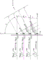
Fig. 4 is a diagram of one example of beamforming between a base station and a user equipment.
Fig. 5 is a diagram of one example of fundamental wave beamforming between a user equipment and a base station.
Fig. 6A is a two-dimensional plot of simulation results for one example of fundamental beamforming at 90 ° using a 2x 2 antenna array.
Fig. 6B is a two-dimensional plot of simulation results for one example of second harmonic beamforming at 90 ° using a 2x 2 antenna array.
Fig. 6C is a two-dimensional plot of simulation results for one example of third harmonic beamforming at 90 ° using a 2x 2 antenna array.
Fig. 7A is a three-dimensional plot of simulation results for one example of fundamental beamforming at 90 ° using a2 × 2 antenna array.
Fig. 7B is a three-dimensional simulation result of one example of second harmonic beamforming at 90 ° using a2 × 2 antenna array.
Fig. 7C is a three-dimensional simulation result of one example of third harmonic beamforming at 90 ° using a2 × 2 antenna array.
Fig. 8A is a two-dimensional plot of simulation results for one example of fundamental beamforming at 50 ° using a2 × 2 antenna array.
Fig. 8B is a two-dimensional plot of simulation results for one example of second harmonic beamforming at 50 ° using a 2x 2 antenna array.
Fig. 8C is a two-dimensional plot of simulation results for one example of third harmonic beamforming at 50 ° using a 2x 2 antenna array.
Fig. 9A is a three-dimensional plot of simulation results for one example of fundamental beamforming at 50 ° using a2 × 2 antenna array.
Fig. 9B is a three-dimensional simulation result of one example of second harmonic beamforming at 50 ° using a2 × 2 antenna array.
Fig. 9C is a three-dimensional simulation result of one example of third harmonic beamforming at 50 ° using a2 × 2 antenna array.
Fig. 10A is a two-dimensional plot of simulation results for one example of fundamental beamforming at 90 ° using a 4x4 antenna array.
Fig. 10B is a two-dimensional plot of simulation results for one example of second harmonic beamforming at 90 ° using a 4x4 antenna array.
Fig. 10C is a two-dimensional plot of simulation results for one example of third harmonic beamforming at 90 ° using a 4x4 antenna array.
Fig. 11A is a three-dimensional plot of simulation results for one example of fundamental beamforming at 90 ° using a 4x4 antenna array.
Fig. 11B is a three-dimensional simulation result of one example of second harmonic beamforming at 90 ° using a 4x4 antenna array.
Fig. 11C is a three-dimensional simulation result of one example of third harmonic beamforming at 90 ° using a 4x4 antenna array.
Fig. 12A is a two-dimensional graph of simulation results for one example of fundamental beamforming at 50 ° using a 4x4 antenna array.
Fig. 12B is a two-dimensional plot of simulation results for one example of second harmonic beamforming at 50 ° using a 4x4 antenna array.
Fig. 12C is a two-dimensional plot of simulation results for one example of third harmonic beamforming at 50 ° using a 4x4 antenna array.
Fig. 13A is a three-dimensional diagram of simulation results of one example of fundamental beamforming at 50 ° using a 4 × 4 antenna array.
Fig. 13B is a three-dimensional simulation result of one example of second harmonic beamforming at 50 ° using a 4x4 antenna array.
Fig. 13C is a three-dimensional simulation result of one example of third harmonic beamforming at 50 ° using a 4x4 antenna array.
Fig. 14A is a three-dimensional plot of simulation results for one example of fundamental beamforming at 90 ° using an 8 x 8 antenna array.
Fig. 14B is a three-dimensional plot of simulation results for one example of fundamental beamforming at 90 ° using a1 × 8 antenna array.
Fig. 15A is a three-dimensional plot of simulation results for one example of fundamental beamforming at 75 ° using an 8 x 8 antenna array.
Fig. 15B is a three-dimensional plot of simulation results for one example of fundamental beamforming at 75 ° using a1 × 8 antenna array.
Fig. 16A is a three-dimensional plot of simulation results for one example of second harmonic beamforming at 75 ° using an 8 x 8 antenna array.
Fig. 16B is a three-dimensional plot of simulation results for one example of second harmonic beamforming at 75 ° using a1 × 8 antenna array.
Fig. 17A is a schematic diagram of another embodiment of an RF system with beam steering.
Fig. 17B is a schematic diagram of another embodiment of an RF system with beam steering.
Fig. 17C is a schematic diagram of another embodiment of an RF system with beam steering.
FIG. 18 is a schematic diagram of one embodiment of a test apparatus with harmonic beamforming based test position determination.
FIG. 19 is a schematic diagram of another embodiment of a test apparatus with harmonic beamforming based test position determination.
FIG. 20 is a schematic diagram of a radiation testing method according to one embodiment.
FIG. 21 is a plan view of one embodiment of a module.
Fig. 22A is a perspective view of another embodiment of a module.
Fig. 22B is a cross-sectional view of the module of fig. 22A taken along line 22B-22B.
FIG. 23 is a schematic diagram of one embodiment of a mobile device.
Detailed Description
The following detailed description of certain embodiments presents various descriptions of specific embodiments. The innovations described herein, however, may be implemented in a number of different ways, for example, as defined and covered by the claims. In the description, reference is made to the drawings wherein like reference numbers may indicate identical or functionally similar elements. It will be understood that the elements shown in the figures are not necessarily drawn to scale. Further, it is understood that some embodiments may include more elements than those shown in the figures and/or subsets of elements shown in the figures. Furthermore, some embodiments may incorporate any suitable combination of features from two or more of the figures.
The International Telecommunications Union (ITU) is a specialized institution of United Nations (UN) responsible for handling global problems related to information and communication technologies, including shared global use of the radio spectrum.
The third generation partnership project (3GPP) is a collaboration between telecommunication standards organizations around the world, such as the radio industry and business Association (ARIB), the Telecommunications Technology Committee (TTC), the Chinese Communication Standardization Association (CCSA), the telecommunications industry solutions Association (ATIS), the Telecommunications Technology Association (TTA), the European Telecommunications Standards Institute (ETSI), and the indian telecommunications standards development association (TSDSI).
Within the scope of the ITU, the 3GPP develops and maintains technical specifications for various mobile communication technologies including, for example, second generation (2G) technologies (e.g., global system for mobile communications (GSM) and enhanced data rates for GSM evolution (EDGE)), third generation (3G) technologies (e.g., Universal Mobile Telecommunications System (UMTS) and High Speed Packet Access (HSPA)), and fourth generation (4G) technologies (e.g., Long Term Evolution (LTE) and LTE-Advanced (LTE-Advanced)), among others.
The technical specifications controlled by 3GPP can be extended and revised by specification releases that can span many years and specify a wide range of new features and evolutions.
In one example, 3GPP introduced Carrier Aggregation (CA) for LTE in release 10. Although two downlink carriers were originally introduced, 3GPP extended carrier aggregation in release 14 to include up to five downlink carriers and up to three uplink carriers. Other examples of new features and evolutions provided by the 3GPP release include, but are not limited to, License Assisted Access (LAA) enhanced LAA (elaa), narrowband internet of things (NB-IOT), vehicle-to-outside world information exchange (V2X), and High Power User Equipment (HPUE).
The 3GPP project introduced stage 1 of the 5 th generation (5G) technology in release 15 (target of 2018) and stage 2 of the 5G technology in release 16 (target of 2019). Release 15 is expected to handle 5G communications below 6GHz, while release 16 is expected to handle communications at and above 6 GHz. Subsequent 3GPP releases will further develop and extend the 5G technology. The 5G technology is also referred to herein as the 5G New air interface (New Radio (NR)).
The preliminary specification of 5G NR supports various features such as millimeter wave spectrum communications, beamforming capability, high spectral efficiency waveforms, low delay communications, multi-path radio numerology, and/or non-orthogonal multiple access (NOMA). While such radio frequency functionality provides flexibility to the network and increases user data rates, supporting such features may present a number of technical challenges.
The teachings herein are applicable to a variety of communication systems, including but not limited to communication systems using Advanced cellular technologies, such as LTE-Advanced, LTE-Advanced Pro, and/or 5G NR, among others.
Fig. 1 is a schematic diagram of one example of a communication network 10. The communication network 10 includes various examples of macro cell base stations 1, small cell base stations 3, and User Equipment (UE), including a first mobile device 2a, a wirelessly connected car 2b, a laptop computer 2c, a fixed wireless device 2d, a wirelessly connected train 2e, and a second mobile device 2 f.
Although specific examples of base stations and user equipment are shown in fig. 1, the communication network may include various types and/or numbers of base stations and user equipment.
For example, in the example shown, the communication network 10 comprises a macrocell base station 1 and a small cell base station 3. Small cell base stations 3 may operate at relatively lower power, shorter range, and/or a smaller number of Concurrent Users (current Users) relative to macro cell base stations 1. The small cell base station 3 may also be referred to as a femto cell, pico cell, or micro cell. Although communication network 10 is shown as including two base stations, communication network 10 may be implemented to include more or fewer base stations and/or other types of base stations.
Although various examples of user equipment are shown, the teachings herein are applicable to a variety of user equipment including, but not limited to, mobile phones, tablets, laptops, internet of things devices, wearable electronics, Customer Premises Equipment (CPE), wirelessly connected vehicles, wireless relays, and/or a variety of other communication devices.
The communication network 10 shown in fig. 1 supports communication using various technologies including, for example, 4G LTE, 5G NR, and Wireless Local Area Networks (WLANs) such as Wi-Fi. While various examples of communication technologies have been provided, the communication network 10 may be adapted to support multiple communication technologies.
Various communication links of the communication network 10 are depicted in fig. 1. The communication links may be duplexed in a number of ways including, for example, using Frequency Division Duplexing (FDD) and/or Time Division Duplexing (TDD). FDD is a radio frequency communication that uses different frequencies to transmit and receive signals. FDD may provide many advantages such as high data rates and low latency. In contrast, TDD is a radio frequency communication that uses approximately the same frequency to transmit and receive signals, and where the transmit and receive communications are switched in time. TDD can provide many advantages such as efficient use of spectrum and variable allocation of throughput between transmit and receive directions.
In some implementations, the user equipment may communicate with the base station using one or more of 4G LTE, 5G NR, and Wi-Fi technologies. In certain implementations, enhanced licensed access (eLAA) is used to aggregate one or more licensed frequency carriers (e.g., licensed 4G LTE and/or 5G NR frequencies) with one or more unlicensed carriers (e.g., unlicensed Wi-Fi frequencies).
The communication link may operate over a wide variety of frequencies. In certain implementations, 5G NR techniques are used to support communication over one or more frequency bands less than 6 gigahertz (GHz) and/or over one or more frequency bands greater than 6 GHz. In one embodiment, one or more mobile devices support HPUE power class specifications.
In some implementations, the base station and/or the user equipment communicate using beamforming. For example, beamforming may be used to focus signal strength to overcome path loss, such as high loss associated with communication at high signal frequencies. In certain embodiments, user devices, such as one or more mobile phones, communicate using beamforming at millimeter-wave frequency bands in the range of 30GHz to 300GHz and/or higher centimeter (upper center) wave frequencies in the range of 6GHz to 30GHz, or more specifically, 24GHz to 30 GHz.
Different users of the communication network 10 may share available network resources, such as available spectrum, in various ways.
In one example, Frequency Division Multiple Access (FDMA) is used to divide a frequency band into multiple frequency carriers. In addition, one or more carriers are allocated to a particular user. Examples of FDMA include, but are not limited to, single-carrier FDMA (SC-FDMA) and orthogonal FDMA (ofdma). OFDM is a multi-carrier technique that subdivides the available bandwidth into multiple mutually orthogonal narrowband subcarriers that can be independently allocated to different users.
Other examples of shared access include, but are not limited to: time Division Multiple Access (TDMA), in which users are allocated to use a specific time slot of a frequency resource; code Division Multiple Access (CDMA), in which frequency resources are shared among different users by assigning each user a unique code; spatial Division Multiple Access (SDMA), where beamforming is used to provide shared access through spatial division; and non-orthogonal multiple access (NOMA), where the power domain is used for multiple access. For example, NOMA may be used to serve multiple users at the same frequency, time, and/or code, but at different power levels (levels).
Enhanced mobile broadband (eMBB) refers to a technique for increasing LTE network system capacity. For example, the eMBB may refer to communications with a peak data rate of at least 10Gbps and a minimum of 100Mbps per user. Ultra-high reliability low latency communications (urrllc) refers to a technique for communications with very low latency (e.g., less than 2 milliseconds). The urrllc may be used for mission critical communications, such as autopilot and/or telesurgical applications. Large-scale machine type communication (mtc) refers to low-cost and low data rate communication associated with wireless connection of everyday objects, such as those associated with internet of things (IoT) applications.
The communication network 10 of fig. 1 may be used to support a wide variety of advanced communication features including, but not limited to, eMBB, urrllc, and/or mtc.
Examples of beam-directed RF systems based on harmonic beamforming
Apparatus and methods related to beamforming of harmonics are provided herein. In certain implementations, a communications apparatus for operating in a wireless network is provided. The communication apparatus includes: an antenna array comprising a plurality of antenna elements that generate a plurality of received signals in response to radio waves; a plurality of signal conditioning circuits operatively associated with the plurality of antenna elements and conditioning the plurality of receive signals to provide beamforming of receive beams; and beam steering circuitry that controls the plurality of signal conditioning circuitry to provide beam steering of the receive beam based on a direction of one or more harmonic lobes (lobes) of the receive beam.
Implementing a communication device in this manner provides a number of advantages. For example, a communication device operating in a network may dynamically manage the direction of beamforming to improve performance in the presence of a receive blocker or jammer (jammer). Thus, the device may operate at higher speeds, lower interference, superior blocking performance, and/or other benefits.
Communication devices using millimeter wave carriers (e.g., 30GHz to 300GHz), centimeter wave carriers (e.g., 3GHz to 30GHz), and/or other carrier frequencies may employ antenna arrays to provide beamforming and directivity for transmission and/or reception of signals.
For example, in the case of signal transmission, an antenna array of m × n antenna elements may be implemented in a planar module, where each antenna element of the array radiates a signal independently. In addition, the signals from the antenna elements are combined using constructive and destructive interference to generate an aggregate transmit signal exhibiting beam-like quality with more signal strength propagating in a given direction away from the antenna array.
In the case of signal reception, the antenna array receives more signal energy when the signal arrives from a particular direction. Thus, the antenna array may also provide directivity for receiving signals.
By increasing the size of the array up to a limit, the relative concentration of signal energy that is concentrated into the beam can be increased. For example, as more signal energy is focused into a transmit beam (transmitted beam), the signal is able to propagate for a longer range while providing sufficient signal levels for RF communications. For example, a signal having a large proportion of the signal energy focused into the transmit beam may exhibit Efficient Isotropic Radiated Power (EIRP).
The signal conditioning circuitry may be used to condition a transmit signal for transmission via the antenna element and/or condition a received signal from the antenna element. In one example, a signal conditioning circuit includes: a phase shifter for controlling a phase shift of the signal; a power amplifier which amplifies a transmission signal to a power level suitable for transmission; and a Low Noise Amplifier (LNA) that amplifies the received signal for further processing when a relatively small amount of noise is introduced. The signal conditioning circuitry may be controlled to direct the beam and/or control the beam intensity.
The inventors of the present application have recognized that when a signal of a fundamental frequency is beamformed to generate a fundamental wave beam, harmonics thereof are also beamformed to form a harmonic wave beam having a smaller beam width (higher directivity) relative to the fundamental wave beam.
In one aspect, the strength and/or direction of signal beams generated by an array of antenna elements is dynamically managed based on one or more considerations related to harmonic lobes or beams. For example, the beam direction may be changed or oriented to reduce or eliminate the effects of harmonic blockage.
The antenna arrays herein may be used to transmit and/or receive signals over a wide range of frequencies, including but not limited to millimeter wave frequencies and centimeter wave frequencies. Antenna arrays may be used in a variety of applications. In one example, an antenna array is included on a module of a communication device. For example, antenna arrays may be used to transmit and/or receive RF signals in base stations and user equipment. In addition, in certain implementations, separate antenna arrays are deployed for transmission and reception.
In some embodiments, the antenna array is implemented on a laminate substrate, wherein the array of antenna elements is formed on a first side of the laminate substrate. In one example, the array of antenna elements comprises patch antenna elements formed from a patterned conductive layer on a first side of the laminate substrate, wherein the ground plane is formed using a conductive layer on a second, opposite side of the laminate substrate or inside the laminate substrate. Other examples of antenna elements include, but are not limited to, dipole antenna elements, ceramic resonators, stamped metal antennas, and/or laser direct structuring antennas.
Fig. 2 is a schematic diagram of one embodiment of an RF system or communication device 110 with beam steering. The RF system 110 includes an antenna array 102, the antenna array 102 including antenna elements 103a1, 103a2. The RF system 110 also includes signal conditioning circuitry 104a1, 104a2.. 9 an, 104b1, 104b2... 104bn, 104m1, 104m2.. 104 mn. RF system 110 also includes a transceiver 105, and transceiver 105 includes a beam steering circuit 106. Beam steering circuitry 106 is also referred to herein as beam steering circuitry.
Although beam steering circuitry 106 is shown in fig. 2 as being included in transceiver 105, beam steering circuitry 106 may be located in any suitable location.
The RF system 110 shows a specific implementation using an m x n antenna array 102 and corresponding signal conditioning circuitry, where m and n are integers greater than or equal to 1 and m + n is greater than 1. The RF system may have more or fewer antenna elements and/or signal conditioning circuitry as indicated by the ellipses. The product of m n may vary depending on the application. In one embodiment, m x n is in the range of 2 to 2048, or more specifically, in the range of 16 to 256. Furthermore, the antenna elements may be arranged in other patterns or configurations, including, for example, linear arrays and/or arrays using non-uniform arrangements of antenna elements.
Each signal conditioning circuit 104a1, 104a2 … 104an, 104b1, 104b2 … 104bn, 104m1, 104m2 … 104mn is coupled to a respective one of the antenna elements 103a1, 103a2 … 103an, 103b1, 103b2 … 103bn, 103m1, 103m2 … 103 mn. The signal conditioning circuit may be used for a variety of purposes, such as controlling phase shift, transmit gain, receive gain, and/or switching.
Although an embodiment is described in which the signal conditioning circuits 104a1, 104a2 … 104an, 104b1, 104b2 … 104bn, 104m1, 104m2 … 104mn provide signal conditioning for both transmit and receive, other implementations are possible. For example, in some implementations, the communication device includes separate arrays for receiving signals and for transmitting signals. Thus, in some embodiments, the signal conditioning circuit is used for transmit conditioning but not receive conditioning, or for receive conditioning but not transmit conditioning.
As shown in fig. 2, the transceiver 105 includes a beam steering circuit 106, the beam steering circuit 106 generating beam steering signals for each of the signal conditioning circuits 104a1, 104a2 … 104an, 104b1, 104b2 … 104bn, 104m1, 104m2 … 104 mn. For example, each beam control signal may be used to control the phase of a variable phase shifter, the gain of a low noise amplifier, and/or the gain of a power amplifier to control characteristics of the transmit and receive beams, such as the direction and/or intensity of the beams. Although beam steering circuitry 106 is included in transceiver 105 in this example, other implementations are possible.
Regarding signal reception, the antenna elements 103a1, 103a2 … 103an, 103b1, 103b2 … 103bn, 103m1, 103m2 … 103mn are used to generate reception signals in response to radio waves. In addition, the signal conditioning circuits 104a1, 104a2 … 104an, 104b1, 104b2 … 104bn, 104m1, 104m2 … 104mn condition the receive signals to provide beamforming of the receive beams.
The beam steering circuitry 106 dynamically manages beamforming associated with the antenna array 102 based on one or more considerations related to the harmonic lobe, such as the direction, strength, and/or beamwidth of the harmonic lobe. In particular, the beam steering circuit 106 controls the signal conditioning circuits 104a1, 104a2 … 104an, 104b1, 104b2 … 104bn, 104m1, 104m2 … 104mn to provide beam steering of the receive beam based on the direction of one or more harmonic lobes of the receive beam.
Since the harmonic lobes are beamformed, controlling the characteristics of the fundamental beam also controls the characteristics of the harmonic beam. Thus, the beam control signal controls not only the intensity and shape of the fundamental beam, but also the harmonic beam or lobe. Accordingly, the beam steering circuit 106 controls the beam direction and/or intensity based on one or more considerations related to the harmonic lobe, such as the likelihood (potential) of the harmonic lobe receiving the blocker signal.
The beam steering circuit 106 steers the receive beam based on a given operating environment at a given time.
Accordingly, the beam steering circuitry 106 reconfigures the antenna array 102 to provide the desired performance characteristics at a given time. For example, the signal conditioning circuits 104a1, 104a2 … 104an, 104b1, 104b2 … 104bn, 104m1, 104m2 … 104mn may be controlled to provide the best or near-best receive beam for a given operating environment at a given time.
Thus, when a pair of communication devices move relative to each other and/or the operating environment changes, a seamless connection between the pair of communication devices may be provided and the beam steering circuit 106 may manage the beams to suppress interference of harmonic lobes associated with receive beamforming to performance.
In the illustrated embodiment, beam steering circuitry 106 also receives one or more inputs. The inputs may include a plurality of signaling factors and/or feedback signals indicative of the communication link (receiving and/or transmitting) and/or operating environment.
Examples of suitable inputs to beam steering circuitry 106 include data relating to the geographic location of one or more devices, a data rate achieved using another device, an observed error rate, a Received Signal Strength Indicator (RSSI), and/or a signal indicating the strength of blockers or harmonics.
These inputs may thus include signals and/or parameters received from another device in and/or from which the radio frequency system 110 communicates with other devices in the network that may be subject to harmonic lobe interference.
Fig. 3A is a schematic diagram of one example of beamforming for providing a transmit beam. Fig. 3A shows a portion of a communication system that includes a first signal conditioning circuit 114a, a second signal conditioning circuit 114b, a first antenna element 113A, and a second antenna element 113 b.
Although shown as including two antenna elements and two signal conditioning circuits, the communication system may include additional antenna elements and/or signal conditioning circuits. For example, fig. 3A illustrates one embodiment of a portion of the communication system 110 of fig. 2.
The first signal conditioning circuit 114a includes a first phase shifter 130a, a first power amplifier 131a, a first Low Noise Amplifier (LNA)132a, and a switch for controlling selection of the power amplifier 131a or the LNA 132 a. In addition, the second signal conditioning circuit 114b includes a second phase shifter 130b, a second power amplifier 131b, a second LNA 132b, and a switch for controlling selection of the power amplifier 131b or the LNA 132 b.
Although one embodiment of a signal conditioning circuit is shown, other implementations of a signal conditioning circuit are possible. For example, in one example, the signal conditioning circuit includes one or more bandpass filters, duplexers, and/or other components. Furthermore, although implementations with analog phase shifters are shown, the teachings herein are also applicable to implementations using digital phase shifting (e.g., phase shifting using digital baseband processing) and implementations using a combination of analog and digital phase shifting.
In the illustrated embodiment, the first antenna element 113a and the second antenna element 113b are separated by a distance d. In addition, fig. 3A has been annotated with an angle θ, which in this example has a value of about 90 ° when the transmit beam direction is substantially perpendicular to the plane of the antenna array and about 0 ° when the transmit beam direction is substantially parallel to the plane of the antenna array.
By controlling the relative phases of the transmit signals provided to the antenna elements 113a, 113b, a desired transmit beam angle θ may be achieved. For example, when the reference value of the first phase shifter 130a is 0 °, the second phase shifter 130b may be controlled to provide a phase shift of about-2 π f (d/ν) cos θ radians, where f is the fundamental frequency of the transmitted signal, d is the distance between the antenna elements, ν is the velocity of the radiated wave, and π is the mathematical constant pi.
In certain implementations, the distance d is implemented to be about 1/2 λ, where λ is the wavelength of the fundamental component of the transmit signal. In such implementations, the second phase shifter 130b may be controlled to provide a phase shift of approximately- π cos θ radians to achieve the transmit beam angle θ.
Accordingly, the relative phases of the phase shifters 130a, 130b may be controlled to provide transmit beamforming. In some implementations, a transceiver (e.g., transceiver 105 of fig. 2) controls phase values of one or more phase shifters to control beamforming.
Fig. 3B is a schematic diagram of one example of beamforming for providing receive beams. Fig. 3B is similar to fig. 3A, except that fig. 3B shows beamforming in the case of a receive beam instead of a transmit beam.
As shown in fig. 3B, the relative phase difference between the first phase shifter 130a and the second phase shifter 130B may be selected to be approximately equal to-2 pi f (d/v) cos θ radians to achieve a desired receive beam angle θ. In implementations where the distance d corresponds to approximately 1/2 λ, the phase difference may be selected to be approximately equal to- π cos θ radians to achieve the receive beam angle θ.
Although various formulas for providing phase values for beamforming have been provided, other phase selection values are possible, such as phase values selected based on the implementation of the antenna array, the implementation of the signal conditioning circuitry, and/or the radio environment.
Fig. 3C is a schematic diagram of another example of beamforming for providing a transmit beam. For the case where the distance d corresponds to about 1/2 λ, fig. 3C is similar to fig. 3A, except that fig. 3C shows additional comments relating to beamforming of the second harmonic. As shown in fig. 3C, the second harmonic is beamformed when the phase difference between the first phase shifter 130a and the second phase shifter 130b is approximately equal to 2 pi cos θ at twice the fundamental frequency or 2 fo.
Fig. 3D is a schematic diagram of another example of beamforming for providing receive beams. For the case where distance D corresponds to about 1/2 λ, fig. 3D is similar to fig. 3B, except that fig. 3D shows additional comments relating to beamforming of the second harmonic. As shown in fig. 3D, the second harmonic is beamformed when the phase difference between the first phase shifter 130a and the second phase shifter 130b is approximately equal to 2 pi cos θ at twice the fundamental frequency or 2 fo.
Therefore, when the phase is pi cos θ, the desired fundamental reception signal is beamformed, and when the phase is 2 pi cos θ, the second harmonic is beamformed.
Fig. 3E is a schematic diagram of another example of beamforming. The illustrated example shows beamforming in the case of four antenna elements 113a-113d and four variable phase shifters 130a-130 d. This example applies to the case of transmit beamforming and receive beamforming.
In the illustrated example, the plurality of phase shifters associated with adjacent antenna elements are approximately in phase Are separated to provide fundamental beamforming. In addition, when the phase difference is approximately equal to
 The nth harmonic is beamformed.
Referring to fig. 3A-3E, in addition to the primary harmonic beam in question, additional harmonic beams may be formed, which may be identified, for example, by simulation (simulation) and/or measurement. Additionally, the described example is one that has been the case for some mathematical models, but there may be factors that cause the fundamental and/or harmonic beam orientations to deviate from the direction indicated (de-stee). These factors include, but are not limited to, the phase shift caused by the transmitter and/or receiver circuitry, the inherent directivity of the individual antenna elements themselves, and/or the operating environment. These factors may be frequency dependent, resulting in different amounts of directional deviation of the fundamental-frequency beam relative to the harmonic beam.
Fig. 4 is a schematic diagram of one example of beamforming between a base station 151 and a user equipment 152.
Fig. 5 is a schematic diagram of one example of fundamental wave beamforming between the user equipment 152 and the base station 151.
As shown in fig. 4 and 5, the base station 151 and the user equipment 152 may communicate using a fundamental wave beam focused toward the counterpart device for long-range communication and high communication rate.
The inventors herein have recognized that when a signal of a fundamental frequency is beamformed to generate a fundamental beam, the harmonic is also beamformed to form a harmonic beam having a smaller beamwidth (higher directivity) relative to the fundamental beam.
In the illustrated example, the harmonic lobes include harmonic lobes that are substantially the same direction as the fundamental beam but have a narrower beamwidth.
Systems and apparatus provided herein may provide beam steering of a receive beam based on a direction of one or more harmonic lobes of the receive beam.
Providing beam steering in this manner provides a number of advantages. For example, a communication device or base station operating in a wireless network may dynamically manage the direction of beamforming to improve performance in the presence of a receive blocker or interferer. Thus, communications may operate at higher speeds, lower interference, superior blocking performance, and/or other benefits.
Fig. 6A-16B illustrate various examples of simulations of fundamental and harmonic beamforming. In these simulations, the length of the lobe (relative to the origin of the graph) is an indication of the electric field strength of the beam. While various results are shown, the results may vary depending on various factors.
Fig. 6A is a two-dimensional plot of simulation results for one example of fundamental beamforming at 90 ° using a 2x 2 antenna array.
Fig. 6B is a two-dimensional plot of simulation results for one example of second harmonic beamforming at 90 ° using a 2x 2 antenna array.
Fig. 6C is a two-dimensional plot of simulation results for one example of third harmonic beamforming at 90 ° using a 2x 2 antenna array.
Fig. 7A is a three-dimensional plot of simulation results for one example of fundamental beamforming at 90 ° using a2 × 2 antenna array.
Fig. 7B is a three-dimensional simulation result of one example of second harmonic beamforming at 90 ° using a2 × 2 antenna array.
Fig. 7C is a three-dimensional simulation result of one example of third harmonic beamforming at 90 ° using a2 × 2 antenna array.
Fig. 8A is a two-dimensional plot of simulation results for one example of fundamental beamforming at 50 ° using a2 × 2 antenna array.
Fig. 8B is a two-dimensional plot of simulation results for one example of second harmonic beamforming at 50 ° using a 2x 2 antenna array.
Fig. 8C is a two-dimensional plot of simulation results for one example of third harmonic beamforming at 50 ° using a 2x 2 antenna array.
Fig. 9A is a three-dimensional plot of simulation results for one example of fundamental beamforming at 50 ° using a2 × 2 antenna array.
Fig. 9B is a three-dimensional simulation result of one example of second harmonic beamforming at 50 ° using a2 × 2 antenna array.
Fig. 9C is a three-dimensional simulation result of one example of third harmonic beamforming at 50 ° using a2 × 2 antenna array.
Fig. 10A is a two-dimensional plot of simulation results for one example of fundamental beamforming at 90 ° using a 4x4 antenna array.
Fig. 10B is a two-dimensional plot of simulation results for one example of second harmonic beamforming at 90 ° using a 4x4 antenna array.
Fig. 10C is a two-dimensional plot of simulation results for one example of third harmonic beamforming at 90 ° using a 4x4 antenna array.
Fig. 11A is a three-dimensional plot of simulation results for one example of fundamental beamforming at 90 ° using a 4x4 antenna array.
Fig. 11B is a three-dimensional simulation result of one example of second harmonic beamforming at 90 ° using a 4x4 antenna array.
Fig. 11C is a three-dimensional simulation result of one example of third harmonic beamforming at 90 ° using a 4x4 antenna array.
Fig. 12A is a two-dimensional graph of simulation results for one example of fundamental beamforming at 50 ° using a 4x4 antenna array.
Fig. 12B is a two-dimensional plot of simulation results for one example of second harmonic beamforming at 50 ° using a 4x4 antenna array.
Fig. 12C is a two-dimensional plot of simulation results for one example of third harmonic beamforming at 50 ° using a 4x4 antenna array.
Fig. 13A is a three-dimensional diagram of simulation results of one example of fundamental beamforming at 50 ° using a 4 × 4 antenna array.
Fig. 13B is a three-dimensional simulation result of one example of second harmonic beamforming at 50 ° using a 4x4 antenna array.
Fig. 13C is a three-dimensional simulation result of one example of third harmonic beamforming at 50 ° using a 4x4 antenna array.
Fig. 14A-16B illustrate various examples of simulations of fundamental and harmonic beamforming. These simulations show a comparison of the beamforming for an 8 × 8 square array and a1 × 8 linear array. While various results are shown, the results may vary depending on various factors.
Fig. 14A is a three-dimensional plot of simulation results for one example of fundamental beamforming at 90 ° using an 8 x 8 antenna array.
Fig. 14B is a three-dimensional plot of simulation results for one example of fundamental beamforming at 90 ° using a1 × 8 antenna array.
Fig. 15A is a three-dimensional diagram of simulation results of one example of fundamental beamforming at 75 ° using an 8 × 8 antenna array.
Fig. 15B is a three-dimensional plot of simulation results for one example of fundamental beamforming at 75 ° using a1 × 8 antenna array.
Fig. 16A is a three-dimensional plot of simulation results for one example of second harmonic beamforming at 75 ° using an 8 x 8 antenna array.
Fig. 16B is a three-dimensional plot of simulation results for one example of second harmonic beamforming at 75 ° using a1 × 8 antenna array.
As these simulations show, beamforming using a linear array can generate a disk-shaped beam pattern. In addition, the dish beam can be tilted into a cone beam by controlling the signals phased (phasing) to the antenna elements of the array. Additionally, a square array may include a superposition of multiple linear arrays of beams side-by-side, forming a relatively narrow composite beam. As shown in fig. 16A and 16B, the harmonics are beamformed to both the linear array and the square array.
Fig. 17A is a schematic diagram of another embodiment of an RF system 170 with beam steering. The RF system 170 includes an antenna array 102 ', a beam steering circuit 106, signal conditioning circuits 154 a', 154b … 154m, and a combiner 165. In addition, antenna array 102' includes antenna elements 103a, 103b … 103 m.
Although an embodiment having three antenna elements and corresponding signal conditioning circuitry is shown, as indicated by the ellipses, the RF system may have more or fewer antenna elements and/or signal conditioning circuitry. Also, the antenna elements may be implemented in an array.
In the embodiment shown in fig. 17A, each signal conditioning circuit includes a phase shifter, a power amplifier, an LNA, and a switch for controlling selection of the power amplifier and the LNA. As shown in fig. 17A, the signal conditioning circuit 154 a' includes a phase shifter 160a, a power amplifier 161a, an LNA 162a, and a set of switches. In addition, the signal conditioning circuit 154b includes a phase shifter 160b, a power amplifier 161b, an LNA 162b, and a set of switches. In addition, the signal conditioning circuit 154m includes a phase shifter 160m, a power amplifier 161m, an LNA 162m, and a set of switches. As shown in fig. 17A, the phase-shifted receive signals from each phase shifter are combined by a combiner 165 to generate a receive beam signal RX.
Although an example of a signal conditioning circuit having a power amplifier and an LNA is shown, other implementations of the signal conditioning circuit are possible. For example, the signal conditioning circuit may include other arrangements of circuits and/or additional circuits including, for example, switches, phase shifters, filters, amplifiers, frequency multiplexers, and/or other components.
As shown in fig. 17A, the signal conditioning circuit 154' also includes a harmonic power detector 163 that provides a detection signal indicative of the magnitude of the harmonic power to the beam steering circuit 106. The detection signal may indicate the power level of one or more harmonic frequencies, such as second and/or third harmonic frequencies.
By including the harmonic power detector 163, the beam steering circuit 106 may determine the total amount of harmonic power received, which may help the beam steering circuit 106 determine the angle at which the receive beam is steered.
Although an embodiment with one harmonic power detector is shown, other signal conditioning circuits may additionally or alternatively include a harmonic power detector. Additionally, although fig. 17A illustrates an embodiment in which the harmonic power detector is located at the output of the LNA, the harmonic power detector may be placed in other locations suitable for detecting harmonic power.
The harmonic power detector 163 may be implemented in a variety of ways, including but not limited to using a peak detector and/or an average detector.
Fig. 17B is a schematic diagram of another embodiment of an RF system 180 with beam steering. The RF system 180 includes an antenna array 102 ', beam steering circuitry 106', signal conditioning circuitry 154a, 154b.
By positioning the harmonic power detector 164 in this manner, the beam steering circuit 106' may control the receive beam RX based on the detected amount of harmonic power present in the beam.
Fig. 17C is a schematic diagram of another embodiment of an RF system 190 with beam steering. The RF system 190 includes an antenna array 102 ', beam steering circuitry 106 ", signal conditioning circuitry 154 a', 154b.
The RF system 190 includes the harmonic power detector 163 of fig. 17A and the harmonic power detector 164 of fig. 17B. Thus, the beam steering circuit 106 ″ is provided with a first detection signal from the harmonic power detector 163, which is indicative of harmonic power in the radio environment; and a second detection signal from the harmonic power detector 164 indicative of an amount of harmonic power of the receive beam. Thus, the beam steering circuitry 106 "controls beam steering based on the amount of harmonic power in the local radio environment and whether the RF system 190 has steered or pointed at the source of the harmonic power.
Examples of test apparatus and test methods using harmonic beamforming-based test position determination
When transmitting from an antenna array using beamforming, the individual signals from the antenna elements of the array combine using constructive and destructive interference to generate an aggregate transmit signal having a beam-like quality with more signal strength propagating in a given direction away from the antenna array. The inventors herein have recognized that when a signal of a fundamental frequency is beamformed to generate a fundamental beam, the harmonic is also beamformed to form a harmonic beam having a smaller beamwidth (higher directivity) relative to the fundamental beam.
Apparatus and methods for harmonic beamforming based radio frequency radiation testing are provided herein. In some configurations, a radiation testing method for radiating a compliant cellular communication assembly is provided. The method includes transmitting a signal beam, which includes a fundamental lobe and one or more harmonic lobes, using an antenna array of a respective cellular communication assembly after manufacturing the cellular communication assembly. The method also includes determining, using the test device, one or more test locations of the signal beam based on detecting the direction of the fundamental lobe, the test locations corresponding to locations associated with the harmonic lobe. The method also includes evaluating, using the test equipment, a harmonic radiation level of each of the one or more test locations, and determining that the respective cellular communication component is compliant with the radiation test when the harmonic radiation level at each test location is determined to be below a predetermined threshold.
Thus, harmonic testing may be performed at a test location associated with a harmonic lobe, thereby concentrating the testing to a location associated with higher harmonics. To reduce the test time, harmonic testing is omitted at locations away from the harmonic lobe. Thus, the cellular communication assembly complies with the radiation test when the harmonic radiation level at the test location is less than the threshold. However, when the harmonic radiation level tested at the one or more test locations is greater than the threshold, the cellular communication is determined to be non-compliant with the radiation test.
By providing radiation testing in this manner, test locations associated with a high likelihood of harmonic radiation may be identified, and fast test times may be achieved. Accordingly, quality assurance checks, platform level tests, calibration tests, certification tests, and/or compliance tests may be performed in a shorter test time. In some embodiments, testing is performed at 10 or fewer test sites, e.g., less than 5 test sites.
In contrast, conventional testing methods may include many test locations, for example, hundreds of test points covering an entire sphere around a cellular communication assembly.
Various types of cellular communication components operating in beamforming may be tested in accordance with the teachings herein. Examples of such cellular communication components include, but are not limited to, packaged semiconductor components (including packaged wafers), radio frequency modules (including multi-chip modules or MCMs) and/or radio frequency devices (e.g., mobile phones, tablets, laptops, and wearable electronic devices). Additionally, these cellular communication components may include partially fabricated components, modules, or devices.
In some embodiments, the radiation test may be performed fully automatically. For example, the test equipment may include an automated handler for moving a device under test (e.g., a module, a mobile phone, or other suitable wireless communication assembly) into and out of a test area (e.g., an anechoic chamber). Additionally, the device under test may generate a transmit beam that is processed by the test equipment to determine the test location of the harmonic radiation. Accordingly, locations associated with harmonic beamforming may be identified and tested to determine whether the device under test passes the harmonic test.
The radiation test may correspond to various types of radiation tests including, but not limited to, a stray radiation test, a second harmonic radiation test, a third harmonic radiation test, a radiated emissions test, a radiated immunity test, and/or an electromagnetic compatibility (EMC). Examples of such tests include, but are not limited to, test specifications, recommendations, and/or regulations promulgated by the International Telecommunications Union (ITU), the third generation partnership project (3GPP), the radio industry and association of enterprises (ARIB), the Telecommunications Technology Committee (TTC), the Chinese Communication Standards Association (CCSA), the telecommunications industry solutions Association (ATIS), the Telecommunications Technology Association (TTA), the European Telecommunications Standards Institute (ETSI), the indian telecommunications standards development association (TSDSI), the Federal Communications Commission (FCC), the American National Standards Institute (ANSI), and/or the International Electrotechnical Commission (IEC).
Radiation testing may be performed in a variety of ways, including, but not limited to, using automated or semi-automated testing equipment operating in wave-absorbing darkrooms, semi-absorbing darkrooms, gigahertz transverse electromagnetic rooms (GTEM), reverberation rooms, RF shielded or RF rooms, Open Area Test Sites (OATS), and/or factory or manufacturing environments such as factory shops.
Radiation testing may be performed at a variety of frequencies, including, for example, millimeter wave carriers (e.g., 30GHz to 300GHz), centimeter wave carriers (e.g., 3GHz to 30GHz), and/or other carrier frequencies.
FIG. 18 is a schematic diagram of one embodiment of a test apparatus 300 with harmonic beamforming based test position determination. The test equipment 300 includes a measurement antenna 301, a signal analyzer 302, a test position determination system 303, a carrier 304, a controller 306, and a temperature unit or controller 307. The test apparatus 300 is used to quickly test a device under test, such as device under test 308, operating in beam forming. Test equipment 300 is also referred to herein as an automated electronic test system or Automated Test Equipment (ATE).
Although FIG. 18 shows a test apparatus according to one embodiment, the teachings herein are applicable to test apparatuses implemented in a variety of ways.
The test apparatus 300 improves manufacturing throughput and/or provides rapid testing of radiation compliance of a device under test after manufacture or partial manufacture. In some implementations, device under test 308 corresponds to a cellular communication component, such as a packaged semiconductor component, a radio frequency module, and/or a radio frequency device.
The test equipment 300 may be used to test the wireless radiation performance of a device under test 308 (e.g., a cellular communication component) to ensure that the device under test 308 operates within predefined performance specifications and parameters. The test apparatus 300 uses an automated device to quickly measure a device under test (e.g., device under test 308) and evaluate the test results. The test apparatus 300 may be used to speed up test time, improve or identify problems with a manufacturing assembly line, and/or reduce the number of defective devices reaching a customer and/or end user.
In some implementations, carrier 304 may include a robotic arm to assist in moving device under test 308 and a suction cup (plunger) for holding device under test 308 to carrier 304 using vacuum suction. However, other implementations of carrier 304 may be used, including, for example, implementations in which carrier 304 otherwise holds device under test 308.
The handler 304 facilitates positioning the device under test 308 in a desired position and/or orientation relative to the components of the test apparatus 300. For example, carrier 304 may be used to place device under test 308 at a desired location relative to measurement antenna 301, thereby allowing the measurement antenna to receive RF waves radiated from device under test 308 in a particular direction and/or distance.
Although the handler 304 may be used to position the device under test 308 relative to the test apparatus 300, additionally and/or alternatively, the test apparatus 300 may include movable and/or rotatable components for controlling the position of components of the test apparatus 300 relative to the device under test 308. In one example, the measurement antenna 301 is included in or on the movable component.
Test position determination system 303 is used to select a test position at which to perform a radiation test. In some implementations, the test position determination system 303 also controls the relative position of the device under test 308 with respect to the measurement antenna 301, thereby coordinating the placement of components for radiation testing. In some embodiments, the test position determination system 303 includes a computer processing unit, a field programmable gate array, a microcontroller, and/or other suitable electronic hardware suitable for processing data and controlling the operation of the test device 300. In some implementations, such hardware operates, in part, based on executing software.
In certain embodiments, device under test 308 and/or measurement antenna 301 is positioned to initially measure or test the fundamental lobe transmitted from device under test 308. In addition, the signal analyzer 302 analyzes the RF signal measurements from the measurement antenna 301 to determine the direction and/or strength of the fundamental lobe transmitted from the device under test 308. Based on the direction and/or intensity of the fundamental lobe, the test location determination system 303 determines one or more test locations for the radiation test. The test position corresponds to a position associated with a harmonic lobe.
In certain implementations, the test location is determined by estimating the location of the harmonic lobe based on using any suitable location estimation algorithm and/or modeling. For example, as described above with reference to fig. 3A-16B, the location of the harmonic lobe is related to the location of the fundamental lobe. Thus, based on data collected by the measurement antenna 301 and the signal analyzer 302 indicating the direction and/or strength of the fundamental lobe, the location of the harmonic lobe can be estimated.
Thereafter, for each test location, device under test 308 and/or measurement antenna 301 may be moved relative to each other, thereby configuring test apparatus 300 to measure the radiation level at the test location. The radiation level at each test location may be measured using the measurement antenna 301 and the signal analyzer 302 and/or using other suitable test components.
The cellular communication assembly complies with the radiation test when the harmonic radiation level at the test location is less than a threshold. However, when the harmonic emission test level at one or more test locations is greater than the threshold, the cellular communication is determined to be non-compliant with the emission test. In certain implementations, the threshold corresponds to an acceptable level of radiation set by a test specification, recommendation, and/or regulation, e.g., as promulgated by any of the regulatory agencies and/or standard agencies described above.
Thus, harmonic testing may be performed at a test location associated with a harmonic lobe, thereby concentrating the testing to a location associated with higher harmonics. To reduce the test time, harmonic testing is omitted at locations away from the harmonic lobe.
By providing radiation testing in this manner, test locations associated with a high likelihood of harmonic radiation may be identified, and fast test times may be achieved. Accordingly, quality assurance checks, platform level tests, calibration tests, certification tests, and/or compliance tests may be performed in a shorter test time. In contrast, conventional testing methods may include a large number of test positions that cover the entire sphere around the device under test.
The temperature unit 307 may be used to control and/or monitor the temperature of the test equipment 300 and/or device under test 308, thereby providing a controlled test environment and/or allowing for a tracked measurement versus temperature relationship. In certain implementations, the test equipment 300 performs radiation testing at two or more different temperatures.
The controller 306 may be used to synchronize and/or provide various control functions associated with components of the test equipment 300, such as the measurement antenna 301, the signal analyzer 302, the test position determination system 303, the handler 304, and/or the temperature unit 307. In some implementations, the controller 306 also controls or instructs the beam emissions of the device under test 308. The controller 306 may be implemented in a variety of ways, including but not limited to using a processor or other suitable electronic hardware. In certain implementations, the controller 306 and other functions of the test device 300, such as the test position determination system 303, are implemented using common hardware (e.g., a computer processing unit, a field programmable gate array, a microcontroller, and/or other suitable electronic hardware).
Although the test apparatus 300 has been shown and described as including certain components for the sake of clarity, the test apparatus 300 may be modified or adjusted in other ways. For example, the test equipment 300 may also include additional components, such as power supplies, sensors, digital signal processing devices, and/or cables, and interconnections.
FIG. 19 is a schematic diagram of another embodiment of a test apparatus 400 with harmonic beamforming based test position determination. The test apparatus 400 comprises a housing 401, a rotatable chamber 402, a rotatable test platform 403, and a measurement antenna 404. In the illustrated embodiment, a device under test 408 (a mobile device in this example) has been positioned in the rotatable chamber 402. As shown in fig. 19, the rotatable chamber 402 includes an inner wall 405, the inner wall 405 operable to inhibit signal reflection to provide an anti-wave feature to the rotatable chamber 402.
In the illustrated embodiment, the platform 402 is rotatable relative to fig. 19 about an axis extending in a vertical direction. In addition, the rotatable chamber 402 is implemented as a cylinder and is rotatable about the axis of the cylinder. In addition, housing 401 includes electronics (e.g., a test position determination system and/or a controller) therein configured to control rotation of platform 403 and rotatable chamber 402, thereby controlling the relative positioning between device under test 408 and measurement antenna 404.
By providing radiation testing in this manner, test locations associated with a high likelihood of harmonic emissions may be identified and fast test times may be achieved. Accordingly, quality assurance checks, platform level tests, calibration tests, certification tests, and/or compliance tests may be performed in a shorter test time.
FIG. 20 is a schematic diagram of a method 450 of radiation testing, according to one embodiment. It is to be appreciated that the method 450 may include more or fewer operations and the operations may be performed in any order as desired. The illustrated method 450 may be used to test a variety of devices under test, including but not limited to cellular communication components. Method 450 may be performed by any suitable testing equipment, such as automated or semi-automated testing equipment. In one embodiment, method 450 is performed by test apparatus 300 in FIG. 18. In another embodiment, method 450 is performed by test apparatus 400 in FIG. 19.
Although method 450 illustrates one embodiment of a method of radiation testing, the teachings herein are applicable to testing methods that are implemented in a variety of ways.
The method 450 begins at block 451, where a signal beam is transmitted using an antenna array of a cellular communication assembly after the cellular communication assembly is manufactured (including in whole or in part), the signal beam including a fundamental lobe and one or more harmonic lobes.
Although shown as beginning at step 451, method 450 may include additional steps prior to step 451. For example, in certain implementations, the cellular communication component is moved (e.g., into a test chamber and/or onto a test platform) using an automated handler (e.g., handler 304 in fig. 18) prior to transmitting the signal beam.
In a subsequent block 452, one or more test locations of the signal beam are determined based on detecting a direction of the fundamental lobe using the test equipment, the one or more test locations corresponding to locations associated with the one or more harmonic lobes. In some configurations, detecting the direction of the fundamental lobe includes receiving a signal beam using one or more measurement antennas (e.g., measurement antenna 301 in fig. 18), analyzing the received signal using a signal analyzer (e.g., signal analyzer 302 in fig. 18), and determining one or more test locations using a test location determination system (e.g., test location determination system 303 in fig. 18).
The method 450 continues at block 453 with evaluating the harmonic radiation level at each test location using the test equipment. In some implementations, by controlling the relative positioning between a cellular communication component (e.g., device under test 308 in fig. 18) and one or more measurement antennas (e.g., measurement antenna 301 in fig. 18), harmonic radiation is measured at each test location until the test location is reached, and the radiation level is measured at the test location using any suitable test equipment (e.g., measurement antenna 301 and signal analyzer 302 in fig. 18).
In a subsequent block 454, the cellular communication component is determined to be in compliance with the radiation test when the level of harmonic radiation at each test location is determined to be below a predetermined threshold.
Thus, the cellular communication assembly complies with the radiation test when the harmonic radiation level at the test location is less than the threshold. However, when the harmonic emission test level at one or more test locations is greater than the threshold, the cellular communication is determined to be non-compliant with the emission test.
Although the method 450 is shown as ending at block 454, the method 450 may be iteratively repeated to test multiple cellular communication components. For example, the method may restart at block 451 for the next cellular communication component.
Examples of RF systems, modules and devices
Figure 21 is a plan view of one embodiment of module 680. Module 680 includes antenna array 681, substrate 682, package 683, IC684, surface mount device or SMD685, integrated passive device or IPD686, and shield 687. Module 680 illustrates various examples of components and structures that may be included in a module of a communication device that provides beam steering.
Although one example of a combination of components and structures is shown, a module may include more or fewer components and/or structures.
Fig. 22A is a perspective view of another embodiment of a module 700. Fig. 22B is a cross-sectional view of the module 700 of fig. 22A taken along line 22B-22B.
The module 700 includes a laminate substrate or laminate 701, a semiconductor die or IC 702 (not visible in fig. 22A), an SMD (not visible in fig. 22A), and an antenna array including antenna elements 710a1, 710a2, 710a3 … 710an 710b1, 710b2, 710b3 … 710bn, 710c1, 710c2, 710c3 … 710cn, 710m1, 710m2, 710m3 … 710 mn.
Although not shown in fig. 22A and 22B, the module 700 may include additional structures and components omitted from the drawings for clarity. In addition, the module 700 may be modified or adapted in a number of ways depending on the needs of a particular application and/or implementation.
Depending on the implementation, the antenna elements 710a1, 710a2, 710a3 … 710an, 710b1, 710b2, 710b3 … 710bn, 710c1, 710c2, 710c3 … 710cn, 710m1, 710m2, 710m3 … 710mn are formed on the first surface of the laminate 701 and may be used to receive and/or transmit signals. Although a 4x4 array of antenna elements is shown, more or fewer antenna elements are possible as indicated by the ellipses. Furthermore, the antenna elements may be arranged in other patterns or configurations, including, for example, using a non-uniform array of antenna elements. Additionally, in another embodiment, multiple antenna arrays are provided, such as separate antenna arrays for transmission and reception.
In the illustrated embodiment, the IC 702 is located on a second surface of the laminate 701 opposite the first surface. However, other implementations are possible. In one example, IC 702 is integrated inside laminate 701.
In certain implementations, the IC 702 includes signal conditioning circuitry associated with the antenna elements 710a1, 710a2, 710a3 … 710an, 710b1, 710b2, 710b3 … 710bn, 710c1, 710c2, 710c3 … 710cn, 710m1, 710m2, 710m3 … 710mn, and beam steering circuitry for dynamically controlling the signal conditioning circuitry based on one or more considerations related to harmonic lobes. Although an implementation with one semiconductor chip is shown, the teachings herein are applicable to implementations with additional chips.
The antenna elements 710a1, 710a2, 710a3 … 710an, 710b1, 710b2, 710b3 … 710bn, 710c1, 710c2, 710c3 … 710cn, 710m1, 710m2, 710m3 … 710mn may correspond to antenna elements implemented in a variety of ways. In one example, the antenna element array comprises patch antenna elements formed from a patterned conductive layer on a first side of the laminate 701, wherein the ground plane is formed using a conductive layer on the opposite side of the laminate 701 or inside the laminate 701. Other examples of antenna elements include, but are not limited to, dipole antenna elements, ceramic resonators, stamped metal antennas, and/or laser direct structuring antennas.
FIG. 23 is a schematic diagram of one embodiment of a mobile device 800. Mobile device 800 includes baseband system 801, sub-millimeter wave (mmW) transceiver 802, sub-millimeter wave front end system 803, sub-millimeter wave antenna 804, power management system 805, memory 806, user interface 807, mmW baseband (BB)/Intermediate Frequency (IF) transceiver 812, mmW front end system 813, and mmW antenna 814.
The mobile device 800 may be configured to communicate using a variety of communication technologies including, but not limited to, 2G, 3G, 4G (including LTE, LTE-Advanced, and LTE-Advanced Pro), 5G NR, WLAN (e.g., Wi-Fi), WPAN (e.g., bluetooth and ZigBee), WMAN (e.g., WiMax), and/or Global Positioning System (GPS) technologies.
In the illustrated embodiment, a sub-millimeter wave transceiver 802, a sub-millimeter wave front-end system 803, and a sub-millimeter wave antenna 804 are used to transmit and receive centimeter and other radio frequency signals below millimeter wave frequencies. In addition, the mmW BB/IF transceiver 812, the mmW front-end system 813, and the mmW antenna 814 are used to transmit and receive millimeter waves. Although one particular example is shown, other implementations are possible, including but not limited to mobile devices that operate using circuitry that operates on different frequency ranges.
Submillimeter-wave transceiver 802 generates RF signals for transmission and processes input RF signals received from submillimeter-wave antenna 804. It will be appreciated that various functions associated with the transmission and reception of RF signals may be implemented by one or more components generally represented in fig. 23 as sub-millimeter wave transceiver 802. In one example, separate components (e.g., separate circuits or dies) may be provided to process certain types of RF signals.
Sub-millimeter wave front end system 803 assists in conditioning signals transmitted to antenna 804 and/or received from antenna 804. In the illustrated embodiment, front-end system 803 includes a Power Amplifier (PA)821, a Low Noise Amplifier (LNA)822, a filter 823, a switch 824, and a duplexer 825. However, other implementations are possible.
For example, sub-millimeter wave front end system 803 may provide a number of functions including, but not limited to, amplifying a signal for transmission, amplifying a received signal, filtering a signal, switching between different frequency bands, switching between different power modes, switching between transmit and receive modes, signal duplexing, signal multiplexing (e.g., duplexing or triplexing), or some combination thereof.
In certain implementations, the mobile device 800 supports carrier aggregation, providing flexibility to increase peak data rates. Carrier aggregation may be used for Frequency Division Duplexing (FDD) and Time Division Duplexing (TDD), and may be used to aggregate multiple carriers or channels. Carrier aggregation includes contiguous aggregation, where contiguous carriers within the same operating frequency band are aggregated. Carrier aggregation may also be non-contiguous and may include carriers that are frequency separated within a common frequency band or within different frequency bands.
Submillimeter-wave antenna 804 may include antennas for a variety of communication types. For example, sub-millimeter wave antenna 804 may include an antenna for transmitting and/or receiving signals associated with a variety of frequencies and communication standards.
The mmW BB/IF transceiver 812 generates millimeter wave signals for transmission and processes input millimeter wave signals received from the mmW antenna 814. It will be appreciated that various functions associated with the transmission and reception of RF signals may be implemented by one or more components, generally represented in fig. 23 as a mmW transceiver 812. Depending on the implementation, mmW BB/IF transceiver 812 may operate at baseband or at an intermediate frequency.
The mmW front-end system 813 assists in conditioning signals transmitted to and/or received from the mmW antenna 814. In the illustrated embodiment, front-end system 803 includes a power amplifier 831, a low noise amplifier 832, a switch 833, an upconverter 834, a downconverter 835 and a phase shifter 836. However, other implementations are possible. In one example, mobile device 800 operates using a BB mmW transceiver, and the mmW front-end system omits the up-converter and down-converter. In another example, the mmW front-end system further includes a filter for filtering the millimeter wave signal.
The mmW antenna 814 may include antennas for a variety of communication types. The mmW antenna 814 may include antenna elements implemented in a variety of ways, and in some configurations, the antenna elements are arranged to form one or more antenna arrays. Examples of antenna elements for millimeter-wave antenna arrays include, but are not limited to, patch antennas, dipole antenna elements, ceramic resonators, stamped metal antennas, and/or laser direct structuring antennas.
In some implementations, mobile device 800 supports MIMO communications and/or switched diversity communications (switched diversity communications). For example, MIMO communication uses multiple antennas to transmit multiple data streams over a single radio frequency channel. MIMO communications benefit from higher signal-to-noise ratios, improved coding, and/or reduced signal interference due to spatial multiplexing differences in the radio environment. Switched diversity refers to communications that select a particular antenna to operate at a particular time. For example, a switch may be used to select a particular antenna from a group of antennas based on a number of factors, such as an observed bit error rate and/or a signal strength indicator.
The mobile device 800 operates with beamforming. For example, mmW front-end system 813 includes a phase shifter with a variable phase controlled by mmW BB/IF transceiver 812. In addition, the phase shifters are controlled to provide beamforming and directivity for transmission and/or reception of signals using the mmW antenna 814. For example, in the case of transmit signals, the phases of the transmit signals provided to the antenna array used for transmission are controlled such that the radiated signals combine using constructive and destructive interference to generate an aggregate transmit signal exhibiting beam-like quality with more signal strength propagating in a given direction. In the case of a received signal, the phase is controlled so that more signal energy is received when the signal arrives at the antenna array from a particular direction.
The baseband system 801 is coupled to a user interface 807 to facilitate processing of various user inputs and outputs (I/O), such as voice and data. The baseband system 801 provides digital representations of the transmit signals to the submillimeter wave and mmW transceivers, which are processed by the transceivers to generate RF signals for transmission. The baseband system 801 also processes the digital representation of the received signal provided by the transceiver. As shown in fig. 23, the baseband system 801 is coupled to memory 806 that facilitates operation of the mobile device 800.
The power management system 805 provides many of the power management functions of the mobile device 800. In certain implementations, the power management system 805 includes a PA supply control circuit that controls a supply voltage of a power amplifier of the front-end system. For example, the power management system 805 may be configured to vary a supply voltage provided to one or more power amplifiers to improve efficiency, such as Power Added Efficiency (PAE).
In certain implementations, the power management system 805 receives a battery voltage from a battery. The battery may be any suitable battery for the mobile device 800, including, for example, a lithium ion battery.
Conclusion
Some embodiments described above provide examples of beam steering related to wireless communication devices. However, the principles and advantages of these embodiments may be applied to any other system or apparatus that benefits from any of the circuits and systems described herein.
Unless the context clearly requires otherwise, throughout the description and the claims, the words "comprise", "comprising", and the like are to be construed in an inclusive sense as opposed to an exclusive or exhaustive sense, that is, in a sense that "includes but is not limited to". As often used herein, the term "coupled" means that two or more elements may be connected directly or by way of one or more intermediate elements. In addition, as often used herein, the term "connected" means that two or more elements may be connected directly or by way of one or more intermediate elements. Additionally, the words "herein," "above," "below," and words of similar import, when used in this application, shall refer to this application as a whole and not to any particular portions of this application. Where the context permits, words in the above detailed description using the singular or plural number may also include the plural or singular number respectively. The word "or" when referring to a list of two or more items, encompasses all of the following interpretations of the word: any of the items in the list, all of the items in the list, and any combination of the items in the list.
Furthermore, conditional language used herein, such as "may," "for example," "such as," and the like, are generally intended to convey that certain embodiments include certain features, elements, and/or states, while other embodiments do not include such features, elements, and/or states, unless expressly stated otherwise, or otherwise understood in the context of such use. Thus, such conditional language is not generally intended to imply: the features, elements, and/or states may be required in any suitable order by one or more embodiments; or one or more embodiments may include logic to determine whether such features, elements, and/or states are included or are to be performed in any particular embodiment, with or without author input or prompting.
The above detailed description of embodiments of the invention is not intended to be exhaustive or to limit the invention to the precise form disclosed above. While specific embodiments of, and examples for, the invention are described above for illustrative purposes, various equivalent modifications are possible within the scope of the invention, as those skilled in the relevant art will recognize. For example, while processes or blocks are presented in a given order, alternative embodiments may perform routines having steps in a different order (routine), or employ systems having blocks in a different order, and some processes or blocks may be deleted, moved, added, subdivided, combined, and/or modified. Each of these processes or blocks may be implemented in a variety of different ways. Also, while processes or blocks are sometimes shown as being performed in series, these processes or blocks may instead be performed in parallel, or may be performed at different times.
The teachings of the invention provided herein can be applied to other systems, not necessarily the systems described above. The elements and acts of the various embodiments described above can be combined to provide further embodiments.
While certain embodiments of the present invention have been described, these embodiments have been presented by way of example only, and are not intended to limit the scope of the application. Indeed, the novel methods and systems described herein may be embodied in a variety of other forms; furthermore, various omissions, substitutions and changes in the form of the methods and systems described herein may be made without departing from the spirit of the application. The drawings and their equivalents are intended to cover such forms or modifications as would fall within the scope and spirit of the application.
Claims (20)
1. A radio frequency system for a cellular network, the radio frequency system comprising:
an antenna array comprising a plurality of antenna elements configured to generate a plurality of received signals in response to radio waves, each of the plurality of antenna elements configured to generate a respective one of the plurality of received signals;
a plurality of signal conditioning circuits, each operatively associated with a respective one of the plurality of antenna elements, the plurality of signal conditioning circuits configured to process the plurality of receive signals to form receive beams; and
beam steering circuitry configured to control the plurality of signal conditioning circuitry to provide beam steering of the receive beam based on a direction of one or more harmonic lobes of the receive beam.
2. The radio frequency system of claim 1, wherein the beam steering circuitry is further configured to detune a fundamental lobe of the receive beam based on a direction of the one or more harmonic lobes.
3. The radio frequency system of claim 2, wherein the one or more harmonic lobes include a harmonic lobe that is directed in substantially the same direction as the fundamental lobe and has a narrower beam width than the fundamental lobe.
4. The radio frequency system of claim 3, wherein the beam steering circuitry is further configured to direct the receive beam within a beamwidth of the fundamental lobe but outside a beamwidth of the one or more harmonic lobes.
5. The radio frequency system of claim 1, wherein the beam steering circuit is operable to periodically adjust the angle of the receive beam.
6. The radio frequency system of claim 1, wherein at least one of the plurality of signal conditioning circuits comprises a harmonic power detector configured to detect a harmonic power magnitude, the beam steering circuit further configured to provide beam steering based on the harmonic power magnitude.
7. The radio frequency system of claim 1, further comprising a harmonic power detector configured to detect a harmonic power magnitude of the receive beam, the beam steering circuit further configured to provide beam steering based on the harmonic power magnitude.
8. The radio frequency system of claim 1, wherein each of the plurality of signal conditioning circuits comprises a variable phase shifter controlled by the beam steering circuit.
9. The radio frequency system of claim 1, wherein the plurality of antenna elements comprises at least one of a plurality of patch antenna elements, a plurality of dipole antenna elements, a plurality of ceramic resonators, a plurality of stamped metal antennas, or a plurality of laser direct structuring antennas.
10. A module for implementation in a user equipment for use in a cellular network, the module comprising:
laminating the substrate;
an antenna array formed on the laminate substrate and including a plurality of antenna elements configured to generate a plurality of reception signals in response to radio waves, each of the plurality of antenna elements configured to generate a respective one of the plurality of reception signals; and
a semiconductor wafer attached to the laminate substrate, the semiconductor wafer including a plurality of signal conditioning circuits each operatively associated with a respective one of the plurality of antenna elements, the plurality of signal conditioning circuits configured to process the plurality of receive signals to form a receive beam, the semiconductor wafer further including beam steering circuitry configured to control the plurality of signal conditioning circuits to provide beam steering of the receive beam based on a direction of one or more harmonic lobes of the receive beam.
11. The module of claim 10, wherein the beam steering circuitry is further configured to detune a fundamental lobe of the receive beam based on a direction of the one or more harmonic lobes.
12. The module of claim 11, wherein the one or more harmonic lobes include harmonic lobes that are directed in substantially the same direction as the fundamental lobe and have a narrower beamwidth than the fundamental lobe.
13. The module of claim 12, wherein the beam steering circuitry is further configured to direct the receive beam within a beamwidth of the fundamental lobe but outside a beamwidth of the one or more harmonic lobes.
14. The module of claim 10, wherein the beam steering circuit is operable to periodically adjust the angle of the receive beam.
15. The module of claim 10, wherein at least one of the plurality of signal conditioning circuits comprises a harmonic power detector configured to detect a harmonic power magnitude, the beam steering circuit further configured to provide beam steering based on the harmonic power magnitude.
16. The module of claim 10, further comprising a harmonic power detector configured to detect a harmonic power magnitude of the receive beam, the beam steering circuit further configured to provide beam steering based on the harmonic power magnitude.
17. The module of claim 10, wherein each of the plurality of signal conditioning circuits comprises a variable phase shifter controlled by the beam steering circuit.
18. A method of beam steering in a radio frequency system, the method comprising:
receiving a plurality of receive signals on a plurality of antenna elements of an antenna array, each of the plurality of receive signals being received by a respective one of the plurality of antenna elements;
adjusting the plurality of received signals using a plurality of signal conditioning circuits, each of the plurality of signal conditioning circuits being operatively associated with a respective one of the plurality of antenna elements;
generating a receive beam by processing the plurality of receive signals using the plurality of signal conditioning circuits; and
directing the receive beam in a selected direction based on a direction of one or more harmonic lobes of the receive beam.
19. The method of claim 18, further comprising detuning a fundamental lobe of the receive beam based on a direction of the one or more harmonic lobes.
20. The method of claim 19, further comprising directing the receive beam within a beamwidth of the fundamental lobe but outside a beamwidth of the one or more harmonic lobes.
Applications Claiming Priority (5)
| Application Number | Priority Date | Filing Date | Title |
|---|---|---|---|
| US201762443304P | 2017-01-06 | 2017-01-06 | |
| US62/443,304 | 2017-01-06 | ||
| US201762509530P | 2017-05-22 | 2017-05-22 | |
| US62/509,530 | 2017-05-22 | ||
| PCT/US2018/012637 WO2018129355A1 (en) | 2017-01-06 | 2018-01-05 | Beamforming of harmonics |
Publications (2)
| Publication Number | Publication Date |
|---|---|
| CN110235384A CN110235384A (en) | 2019-09-13 |
| CN110235384B true CN110235384B (en) | 2022-02-08 |
Family
ID=62791408
Family Applications (1)
| Application Number | Title | Priority Date | Filing Date |
|---|---|---|---|
| CN201880009000.4A Active CN110235384B (en) | 2017-01-06 | 2018-01-05 | Harmonic beamforming |
Country Status (7)
| Country | Link |
|---|---|
| US (3) | US10236966B2 (en) |
| JP (2) | JP7063907B2 (en) |
| KR (1) | KR102652348B1 (en) |
| CN (1) | CN110235384B (en) |
| DE (1) | DE112018000326T5 (en) |
| GB (3) | GB2601078A (en) |
| WO (1) | WO2018129355A1 (en) |
Families Citing this family (18)
| Publication number | Priority date | Publication date | Assignee | Title |
|---|---|---|---|---|
| GB2517437A (en) * | 2013-08-19 | 2015-02-25 | Mahle Int Gmbh | Sliding Engine Component |
| JP7063907B2 (en) | 2017-01-06 | 2022-05-09 | スカイワークス ソリューションズ,インコーポレイテッド | Harmonic beamforming |
| US11189901B2 (en) | 2017-12-11 | 2021-11-30 | X Development Llc | Using phased arrays of waveguide couplers in waveguide cavities to prevent illegitimate reception of power |
| US10854943B2 (en) | 2017-12-11 | 2020-12-01 | X Development Llc | Using phased arrays of waveguide couplers to excite earth-ionosphere low loss modes |
| US10852333B2 (en) * | 2017-12-11 | 2020-12-01 | X Development Llc | Earth-ionosphere waveguide power transfer |
| US10739450B2 (en) | 2017-12-11 | 2020-08-11 | X Development Llc | Using phased arrays of waveguide couplers in waveguide cavities to detect loading |
| US10924164B2 (en) | 2018-05-29 | 2021-02-16 | Skyworks Solutions, Inc. | Beamforming communication systems with power control based on antenna pattern configuration |
| US10826570B2 (en) | 2018-05-31 | 2020-11-03 | Skyworks Solutions, Inc. | Apparatus and methods for multi-antenna communications |
| EP3609088A1 (en) * | 2018-08-06 | 2020-02-12 | Intel Corporation | Techniques for analog beamforming |
| US20200076488A1 (en) | 2018-08-30 | 2020-03-05 | Skyworks Solutions, Inc. | Beamforming communication systems with sensor aided beam management |
| KR102659215B1 (en) * | 2018-11-19 | 2024-04-22 | 삼성전자주식회사 | A method for measuring the performance of an antenna and an antenna chamber performing thereof |
| CN111698187A (en) | 2019-12-13 | 2020-09-22 | 广东工业大学 | Frequency division multiple access communication method based on harmonic modulation technology |
| CN111929508B (en) * | 2020-07-16 | 2022-12-27 | 中国电子科技集团公司第四十一研究所 | Electric thickness information extraction method and device capable of resisting environmental drift |
| CN111988783B (en) * | 2020-08-04 | 2022-04-22 | 中国人民解放军国防科技大学 | Safe transmission method and system for uplink non-orthogonal multiple access |
| CN112186341B (en) * | 2020-09-29 | 2021-12-28 | 华南理工大学 | Base station antenna, low-frequency radiation unit and radiation arm |
| US11916303B2 (en) * | 2021-04-21 | 2024-02-27 | Skyworks Solutions, Inc. | Antenna array having antenna elements interconnected by material for controlling beamforming |
| CN115243275A (en) * | 2021-04-25 | 2022-10-25 | 华为技术有限公司 | Communication method and device |
| KR102544383B1 (en) | 2021-07-06 | 2023-06-16 | 주식회사 큐셀네트웍스 | apparatus and system for testing base station antenna of mobile telecommunication |
Citations (4)
| Publication number | Priority date | Publication date | Assignee | Title |
|---|---|---|---|---|
| WO1999025142A2 (en) * | 1997-11-05 | 1999-05-20 | Nokia Telecommunications Oy | Method of improving quality of radio connection |
| CN101860779A (en) * | 2010-05-21 | 2010-10-13 | 中国科学院声学研究所 | Time domain broadband harmonic region beam former and beam forming method for spherical array |
| CN104067143A (en) * | 2011-09-09 | 2014-09-24 | 阿斯泰克斯有限责任公司 | Imaging radar sensor with narrow antenna lobe and wide angle-detection range |
| CN104246530A (en) * | 2012-04-18 | 2014-12-24 | 瑞典爱立信有限公司 | An antenna arrangement for DOA estimation |
Family Cites Families (31)
| Publication number | Priority date | Publication date | Assignee | Title |
|---|---|---|---|---|
| US4213131A (en) * | 1979-05-14 | 1980-07-15 | The United States Of America As Represented By The Administrator Of The National Aeronautics And Space Administration | Scannable beam forming interferometer antenna array system |
| KR100521854B1 (en) * | 1997-03-03 | 2005-10-14 | 셀레트라 리미티드 | Cellular communications systems |
| JP3332329B2 (en) * | 1997-06-02 | 2002-10-07 | 株式会社エヌ・ティ・ティ・ドコモ | Adaptive array antenna device |
| US5955992A (en) * | 1998-02-12 | 1999-09-21 | Shattil; Steve J. | Frequency-shifted feedback cavity used as a phased array antenna controller and carrier interference multiple access spread-spectrum transmitter |
| JP2001053661A (en) | 1999-08-09 | 2001-02-23 | Kyocera Corp | Transmission and reception system adjustment method for adaptive array base station, and adaptive array radio device |
| JP3565140B2 (en) | 2000-06-05 | 2004-09-15 | 三菱電機株式会社 | Array antenna device |
| BR0214200A (en) | 2001-11-09 | 2004-12-21 | Ipr Licensing Inc | Directional Antenna and its use |
| AU2002330817A1 (en) * | 2002-08-30 | 2004-03-19 | Telefonaktiebolaget L M Ericsson (Publ) | Method for enhancing the measuring accuracy in an antenna array |
| JP3896059B2 (en) | 2002-09-27 | 2007-03-22 | ジーイー・メディカル・システムズ・グローバル・テクノロジー・カンパニー・エルエルシー | Ultrasonic diagnostic equipment |
| US7338448B2 (en) * | 2003-11-07 | 2008-03-04 | Ge Medical Systems Global Technology Company, Llc | Method and apparatus for ultrasound compound imaging with combined fundamental and harmonic signals |
| CN102664661A (en) | 2004-08-12 | 2012-09-12 | 美商内数位科技公司 | Base station, wireless transmit/receive unit and method |
| KR100654316B1 (en) | 2004-12-08 | 2006-12-08 | 한국과학기술원 | Orthogonal Frequency and Code Hopping Multiplexing Communications Method |
| FR2898684B1 (en) * | 2006-03-20 | 2008-05-16 | Sagem Comm | METHOD FOR MEASURING PARASITE EMISSIONS AND HARMONICS OF A MOBILE TELEPHONY TERMINAL, MEASUREMENT SYSTEM THEREFOR |
| US7312751B1 (en) * | 2006-10-30 | 2007-12-25 | The Boeing Company | Phased array antenna system to achieve suppression of undesired signal components |
| ITPI20070012A1 (en) | 2007-02-14 | 2008-08-15 | Univ Pisa | METHOD OF PROCESSING DATA MULTI-ASSASSMENT RADAR FOR DETECTION AND ANALYSIS OF MULTIPLE COMPONENTS OF NON-STATIONARY REPRODUCERS |
| US7728769B2 (en) * | 2008-03-12 | 2010-06-01 | Raytheon Company | Adaptive processing method of clutter rejection in a phased array beam pattern |
| US9002287B2 (en) | 2009-10-09 | 2015-04-07 | Apple Inc. | System for testing multi-antenna devices |
| US9806789B2 (en) * | 2010-04-06 | 2017-10-31 | Samsung Electronics Co., Ltd. | Apparatus and method for spatial division duplex (SDD) for millimeter wave communication system |
| US8681890B2 (en) | 2010-06-07 | 2014-03-25 | Entropic Communications, Inc. | Method and apparatus for real time multiplexing with receiver and antenna array elements |
| US20120249366A1 (en) * | 2011-04-04 | 2012-10-04 | Raytheon Company | Communications on the move antenna system |
| KR101820733B1 (en) | 2011-08-24 | 2018-01-22 | 삼성전자주식회사 | Apparatus and method for selecting beam in wireless communication system |
| JP2013187740A (en) | 2012-03-08 | 2013-09-19 | Renesas Electronics Corp | Semiconductor device |
| US9042323B1 (en) * | 2013-01-18 | 2015-05-26 | Sprint Spectrum L.P. | Method and system of activating a global beam in a coverage area |
| US9929466B2 (en) | 2013-03-13 | 2018-03-27 | The Regents Of The University Of California | Self-steering antenna arrays |
| US9666942B2 (en) * | 2013-03-15 | 2017-05-30 | Gigpeak, Inc. | Adaptive transmit array for beam-steering |
| JP2015103903A (en) | 2013-11-22 | 2015-06-04 | 株式会社日立製作所 | Radio communication system and radio communication method |
| JP2015132474A (en) | 2014-01-09 | 2015-07-23 | 株式会社村田製作所 | Phased array antenna assembly, and active sensor |
| GB2539734A (en) | 2015-06-25 | 2016-12-28 | Airspan Networks Inc | An antenna apparatus and method of performing spatial nulling within the antenna apparatus |
| GB2539733A (en) * | 2015-06-25 | 2016-12-28 | Airspan Networks Inc | An antenna apparatus and method of configuring a transmission beam for the antenna apparatus |
| EP3109939B1 (en) * | 2015-06-26 | 2024-01-03 | HENSOLDT Sensors GmbH | Dual-band phased array antenna with built-in grating lobe mitigation |
| JP7063907B2 (en) | 2017-01-06 | 2022-05-09 | スカイワークス ソリューションズ,インコーポレイテッド | Harmonic beamforming |
-
2018
- 2018-01-05 JP JP2019536512A patent/JP7063907B2/en active Active
- 2018-01-05 US US15/862,949 patent/US10236966B2/en active Active
- 2018-01-05 GB GB2201878.2A patent/GB2601078A/en not_active Withdrawn
- 2018-01-05 US US15/862,968 patent/US10145878B2/en active Active
- 2018-01-05 GB GB2201875.8A patent/GB2600865B/en active Active
- 2018-01-05 WO PCT/US2018/012637 patent/WO2018129355A1/en active Application Filing
- 2018-01-05 GB GB1909640.3A patent/GB2573896A/en not_active Withdrawn
- 2018-01-05 CN CN201880009000.4A patent/CN110235384B/en active Active
- 2018-01-05 DE DE112018000326.4T patent/DE112018000326T5/en active Pending
- 2018-01-05 KR KR1020197021953A patent/KR102652348B1/en active IP Right Grant
-
2019
- 2019-02-13 US US16/274,564 patent/US10670644B2/en active Active
-
2022
- 2022-04-21 JP JP2022069974A patent/JP7185084B2/en active Active
Patent Citations (4)
| Publication number | Priority date | Publication date | Assignee | Title |
|---|---|---|---|---|
| WO1999025142A2 (en) * | 1997-11-05 | 1999-05-20 | Nokia Telecommunications Oy | Method of improving quality of radio connection |
| CN101860779A (en) * | 2010-05-21 | 2010-10-13 | 中国科学院声学研究所 | Time domain broadband harmonic region beam former and beam forming method for spherical array |
| CN104067143A (en) * | 2011-09-09 | 2014-09-24 | 阿斯泰克斯有限责任公司 | Imaging radar sensor with narrow antenna lobe and wide angle-detection range |
| CN104246530A (en) * | 2012-04-18 | 2014-12-24 | 瑞典爱立信有限公司 | An antenna arrangement for DOA estimation |
Also Published As
| Publication number | Publication date |
|---|---|
| KR20190095955A (en) | 2019-08-16 |
| GB2573896A (en) | 2019-11-20 |
| US10670644B2 (en) | 2020-06-02 |
| JP2022106819A (en) | 2022-07-20 |
| US10145878B2 (en) | 2018-12-04 |
| GB2601078A (en) | 2022-05-18 |
| US20180224490A1 (en) | 2018-08-09 |
| JP2020505808A (en) | 2020-02-20 |
| CN110235384A (en) | 2019-09-13 |
| DE112018000326T5 (en) | 2019-10-10 |
| US10236966B2 (en) | 2019-03-19 |
| GB202201878D0 (en) | 2022-03-30 |
| KR102652348B1 (en) | 2024-03-27 |
| GB2600865A (en) | 2022-05-11 |
| JP7185084B2 (en) | 2022-12-06 |
| GB201909640D0 (en) | 2019-08-21 |
| JP7063907B2 (en) | 2022-05-09 |
| US20180227034A1 (en) | 2018-08-09 |
| WO2018129355A1 (en) | 2018-07-12 |
| GB202201875D0 (en) | 2022-03-30 |
| GB2600865B (en) | 2022-11-30 |
| US20190178927A1 (en) | 2019-06-13 |
Similar Documents
| Publication | Publication Date | Title |
|---|---|---|
| CN110235384B (en) | Harmonic beamforming | |
| US11424541B2 (en) | Frequency and polarization reconfigurable antenna systems | |
| US8849217B2 (en) | Antenna arrangement | |
| CN110875765A (en) | Beamforming communication system with sensor-assisted beam management | |
| US20210159949A1 (en) | Beamforming communication systems with power amplifier output impedance tuning control | |
| US7557758B2 (en) | Very high frequency dielectric substrate wave guide | |
| US8750798B2 (en) | Multiple input multiple output antenna module and associated method | |
| US20220263240A1 (en) | Interference aware adaption of antenna radiation patterns | |
| US11528066B2 (en) | Non-orthogonal multiple-access and multi-finger beamforming | |
| US11735815B2 (en) | Reconfigurable antenna systems integrated with metal case | |
| WO2016007138A1 (en) | System, method and computer-readable medium for estimating direction of arrival of a signal incident on at least one antenna array | |
| Psychoudakis et al. | Mobile station radio frequency unit for 5G communications at 28GHz | |
| Letavin et al. | Antenna for mobile communication of the 5th generation | |
| EP3667816B1 (en) | Device for testing beam forming processor | |
| Lu | Interference suppression techniques for millimeter-wave integrated receiver front ends |
Legal Events
| Date | Code | Title | Description |
|---|---|---|---|
| PB01 | Publication | ||
| PB01 | Publication | ||
| SE01 | Entry into force of request for substantive examination | ||
| SE01 | Entry into force of request for substantive examination | ||
| REG | Reference to a national code |
Ref country code: HK Ref legal event code: DE Ref document number: 40012775 Country of ref document: HK |
|
| GR01 | Patent grant | ||
| GR01 | Patent grant |