EP2180192A1 - Gas compression device and method of controlling gas compression device - Google Patents
Gas compression device and method of controlling gas compression device Download PDFInfo
- Publication number
- EP2180192A1 EP2180192A1 EP08790929A EP08790929A EP2180192A1 EP 2180192 A1 EP2180192 A1 EP 2180192A1 EP 08790929 A EP08790929 A EP 08790929A EP 08790929 A EP08790929 A EP 08790929A EP 2180192 A1 EP2180192 A1 EP 2180192A1
- Authority
- EP
- European Patent Office
- Prior art keywords
- gas
- flow rate
- compression
- compression means
- demand
- Prior art date
- Legal status (The legal status is an assumption and is not a legal conclusion. Google has not performed a legal analysis and makes no representation as to the accuracy of the status listed.)
- Withdrawn
Links
Images


Classifications
-
- F—MECHANICAL ENGINEERING; LIGHTING; HEATING; WEAPONS; BLASTING
- F04—POSITIVE - DISPLACEMENT MACHINES FOR LIQUIDS; PUMPS FOR LIQUIDS OR ELASTIC FLUIDS
- F04D—NON-POSITIVE-DISPLACEMENT PUMPS
- F04D17/00—Radial-flow pumps, e.g. centrifugal pumps; Helico-centrifugal pumps
- F04D17/08—Centrifugal pumps
- F04D17/10—Centrifugal pumps for compressing or evacuating
- F04D17/12—Multi-stage pumps
-
- F—MECHANICAL ENGINEERING; LIGHTING; HEATING; WEAPONS; BLASTING
- F04—POSITIVE - DISPLACEMENT MACHINES FOR LIQUIDS; PUMPS FOR LIQUIDS OR ELASTIC FLUIDS
- F04D—NON-POSITIVE-DISPLACEMENT PUMPS
- F04D27/00—Control, e.g. regulation, of pumps, pumping installations or pumping systems specially adapted for elastic fluids
- F04D27/02—Surge control
- F04D27/0207—Surge control by bleeding, bypassing or recycling fluids
-
- F—MECHANICAL ENGINEERING; LIGHTING; HEATING; WEAPONS; BLASTING
- F04—POSITIVE - DISPLACEMENT MACHINES FOR LIQUIDS; PUMPS FOR LIQUIDS OR ELASTIC FLUIDS
- F04D—NON-POSITIVE-DISPLACEMENT PUMPS
- F04D27/00—Control, e.g. regulation, of pumps, pumping installations or pumping systems specially adapted for elastic fluids
- F04D27/02—Surge control
- F04D27/0246—Surge control by varying geometry within the pumps, e.g. by adjusting vanes
-
- F—MECHANICAL ENGINEERING; LIGHTING; HEATING; WEAPONS; BLASTING
- F04—POSITIVE - DISPLACEMENT MACHINES FOR LIQUIDS; PUMPS FOR LIQUIDS OR ELASTIC FLUIDS
- F04D—NON-POSITIVE-DISPLACEMENT PUMPS
- F04D27/00—Control, e.g. regulation, of pumps, pumping installations or pumping systems specially adapted for elastic fluids
- F04D27/02—Surge control
- F04D27/0284—Conjoint control of two or more different functions
Definitions
- the present invention relates to a gas compression device that is provided with a plurality of compression means that are driven by a single drive means, and a method for controlling the gas compression device.
- a turbo compression device gas compression device that is provided with a plurality of centrifugal compressors (compression means) that are linked by a shaft that is driven by a single motor (drive means) has conventionally been employed.
- the plurality of centrifugal compressors are arranged in series in the flow direction of the gas, so that the gas is gradually compressed in each centrifugal compressor.
- the amount of compressed gas that is required changes with time. That is, the amount of the compressed gas that is supplied from the turbo compression device to a device at the demand end changes with time.
- the present invention was achieved in view of the above circumstances, and has as its object, in a gas compression device that compresses gas by a plurality of compression means that are arranged in series with respect to the gas flow direction, to reduce the energy consumption by sufficiently reducing the load of a drive means while suppressing the occurrence of surging in the compression means.
- the gas compression device that is the first embodiment of the present invention is a gas compression device that arranges a plurality of compression means provided with impellers that impart velocity energy to a gas, and a diffuser that converts the velocity energy to pressure energy in series in the flow direction of gas, and supplies the gas that is compressed via the plurality of the compression means to a predetermined demand end, provided with a drive means that supplies power to the impeller; a flow rate adjusting means that adjusts the flow rate of the gas that is drawn into the compression means that is positioned furthest upstream with respect to the flow direction of the gas; a circulation and supply means that is capable of circulating and supplying at least a portion of the gas that is discharged from the compression means that is positioned furthest downstream with respect to the flow direction of the gas to the diffuser or is positioned between the diffuser and the impeller of each compression means, and a control means that controls at least the drive means, the flow rate adjusting means, and the circulation and supply means, in which the control
- the flow rate adjusting means is controlled in accordance with the demand amount of gas of the demand end. That is, in the case of the demand amount of gas of the demand end decreasing, the flow rate of gas that is drawn into the gas compression device is reduced in accordance with this decrement.
- each compression means in the case of the flow rate of the gas that is drawn in falling below a set value that is set based on a surging limit in the compression means, a portion of the gas in the compression means is circulated and supplied to the diffuser or between the diffuser and the impeller of each compression means.
- the gas compression device may be provided with a pressure detecting means that detects the pressure of the gas that is discharged from the compression means that is positioned furthest downstream, and a flow rate detecting means that detects the flow rate of the gas that is discharged from the compression means that is positioned furthest downstream, and the control means may perform control of the flow rate adjusting means with at least the detection result of the pressure detecting means serving as the demand amount of the gas of the demand end, among the pressure detecting means and the flow rate detecting means.
- the control means may start circulation and supply of the gas by the circulation and supply means in stages from the compression means that is positioned furthest downstream toward the upstream compression means.
- the set value may be a value that matches the flow rate of the surging limit in the compression means and a predetermined margin.
- the control means in the case of the demand amount of the gas of the demand end being zero, may maintain the intake of the gas in the compression means that is positioned furthest upstream with respect to the flow direction of the gas, and exhaust a portion of the gas that is discharged from the compression means that is positioned furthest downstream with respect to the flow direction of the gas without supplying it to the demand end.
- a method of controlling a gas compression device that is the second embodiment of the present invention is a method of controlling a gas compression device that arranges a plurality of compression means provided with an impeller that imparts velocity energy to a gas and a diffuser that converts the velocity energy to pressure energy in series in the flow direction of gas, and supplies the gas that is compressed via the plurality of the compression means to a predetermined demand end, comprising the steps of: adjusting the flow rate of gas that is drawn into the compression means that is positioned furthest upstream with respect to the flow direction of the gas in accordance with a demand amount of the gas at the demand end, and in each compression means, circulating and supplying at least a portion of the gas that is discharged from the compression means that is positioned furthest downstream with respect to the flow direction of the gas to the diffuser or between the diffuser and the impeller of each compression means in the case of the flow rate of the gas that is drawn in falling below a set value that is set based on a surging limit in the compression means.
- the flow rate of the gas that is drawn into the gas compression device is controlled. That is, in the case of the demand amount of the gas at the demand end device having decreased, the flow rate of the gas that is drawn into the gas compression device is reduced in proportion to this decrement.
- each compression means in the case of the flow rate of the gas that is drawn in falling below a set value that is set based on a surging limit in the compression means, in the compression means, a portion of the gas that is discharged from the compression means that is positioned furthest downstream is circulated and supplied to the diffuser or between the diffuser and the impeller of each compression means.
- Detecting the pressure and the flow rate of the gas that is discharged from the compression means that is positioned furthest downstream and, among the detection result, controlling the flow rate of the gas that is drawn into the compression means that is positioned furthest upstream may be performed with at least the pressure serving as the demand amount of the gas at the demand end.
- the circulation and supply of the gas may be started in stages from the compression means that is positioned furthest downstream toward the upstream compression means.
- the set value may be a value that matches the flow rate of the surging limit in the compression means and a predetermined margin.
- maintaining the intake of the gas in the compression means that is positioned furthest upstream with respect to the flow direction of the gas, and exhausting a portion of the gas that is discharged from the compression means that is positioned furthest downstream with respect to the flow direction of the gas without supplying it to the demand end may be performed.
- the flow rate of gas that is drawn into the gas compression device is controlled in accordance with the demand amount of gas at the demand end. That is, in the case of the demand amount of the gas at the demand end device having decreased, the flow rate of the gas that is drawn into the gas compression device is reduced in proportion to this decrement.
- each compression means in the case of the flow rate of the gas that is drawn in falling below a set value that is set based on a surging limit in the compression means, in the compression means, a portion of the gas that is discharged from the compression means that is positioned furthest downstream is circulated and supplied to the diffuser or between the diffuser and the impeller of each compression means.
- the gas that is circulated and supplied flows to the diffuser without being supplied to the impeller. For this reason, it is possible to supply gas of a sufficient flow rate to the diffuser without increasing the load on the impeller, and it is possible to suppress the occurrence of stalling and the occurrence of surging without increasing the load to the drive means. That is, however low the flow rate of the gas that is drawn into each compression means, it is possible to cause a flow of gas with a flow rate that enables suppression of surging to the diffuser of the compression means.
- a gas compression device that compresses gas by a plurality of compression means that are provided in series with respect to the flow direction of gas, it is possible to reduce energy consumption by sufficiently reducing the load of the drive means while suppressing the occurrence of surging in the compression means.
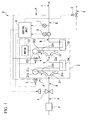
- FIG 1 is a block drawing that shows the outline constitution of a turbo compression device S (gas compression device) of the present embodiment.
- the turbo compression device S of the present embodiment is provided with an inlet guide vane 1 (flow rate adjusting means), a gas compression portion 2, a first circulation and supply control valve 3 (circulation and supply means), a second circulation and supply control valve 4 (circulation and supply means), an exhaust control valve 5, a flow rate detector 6 (flow rate detecting means), a pressure detector 7 (pressure detecting means), and a control unit 8 (control means).
- the inlet guide vane 1 is for adjusting the flow rate of gas that is drawn into the gas compression portion 2, and is controlled by the control unit 8.
- the gas compression portion 2 has a constitution in which two (a plurality of) centrifugal compressors 21 and 22 (compression means) are arranged in series in the flow direction of the gas.
- the gas that is drawn into the gas compression portion 2 via the inlet guide vane 1 is first drawn into the centrifugal compressor 21 that is positioned on the upstream side (furthest upstream) with respect to the flow direction of the gas. That is, the inlet guide vane 1 adjusts the flow rate of gas that is drawn into the centrifugal compressor 21 that is positioned furthest upstream with respect to the gas flow direction.
- This inlet guide vane 1 imparts a twist to the gas in the same direction as the rotation direction of an impeller 21a (refer to FIG. 2 ) that the centrifugal compressor 21 is equipped with. Thereby, the workload of the impellor of the centrifugal compressor 21 is decreased.
- the inlet guide vane 1 As a substitute for the inlet guide vane 1, it is also possible to use a butterfly valve. In this case, the flow rate of the gas that is drawn in is adjusted by applying resistance to the gas without imparting a twist to the gas.
- the gas compression portion 2 is provided with two centrifugal compressors 21 and 22 (compression means) that are arranged in the gas flow direction, a motor 23 (drive means) that supplies rotation power to the impellers 21a and 22a that are provided in the centrifugal compressors 21 and 22, an intercooler 24 that cools the gas that is discharged from the centrifugal compressor 21 (hereinbelow referred to as the first centrifugal compressor 21) located on the upstream side with respect to the flow direction of the gas, and an aftercooler 25 that cools the gas that is discharged from the centrifugal compressor 22 (hereinbelow referred to as the second centrifugal compressor 22) located on the downstream side with respect to the flow direction of the gas.
- the first centrifugal compressor 21 located on the upstream side with respect to the flow direction of the gas
- an aftercooler 25 that cools the gas that is discharged from the centrifugal compressor 22 located on the downstream side with respect to the flow direction of the gas.
- FIG 2 is a cross-sectional view for describing the outline constitution of the first centrifugal compressor 21 and the second centrifugal compressor 22. Since the first centrifugal compressor 21 and the second centrifugal compressor 22 have the same constitution, in FIG. 2 , only one centrifugal compressor is shown. Also, in FIG 2 , reference numerals without parentheses refer to the first centrifugal compressor 21, while reference numerals with parentheses refer to the second centrifugal compressor 22.
- the centrifugal compressor 21 (22) is provided with a casing main body 21c (22c) that has a scroll flow path 21b (22b) of which one side opens and extends in the circumferential direction toward the portion in the vicinity of the inner peripheral edge, a gas discharge pipe 21d (22d) that is provided at a predetermined location of the casing main body 21c so as to continue to the scroll flow path 21b (22b), a rotor shaft 21f(22f) that rotatably passes through a seal member 21e (22e) that is provided in the center of the other wall portion of the casing main body 21c (22c), an impeller 21a (22a) that is positioned in the center in the inner portion of the casing main body 21c (22c) and that is coupled to the rotor shaft 21f(22f), a ring-shaped casing lid 21i (22i) that fits in the opening portion of the casing main body 21c (22c) so as to cover this impeller 21
- the rotor shaft 21f of the first centrifugal compressor 21 and the rotor shaft 22f of the second centrifugal compressor 22 are each connected with the motor 23 via a gearwheel acceleration mechanism. Then the impeller 21a (22a) rotates at a rotation speed corresponding to the output of the motor 23.
- the diffuser vane 21j (22j) is integrally formed with respect to the ring-shaped vane support seat 211 (221) that is installed in a cavity portion 21k (22k) that is provided so as to surround the impeller 21a (22a) in the interior of the casing main body 21c (22c).
- the flow path cross-sectional shape of the scroll flow path 21b (22b) is formed so as to become larger as the gas discharge pipe 21d (22d) is approached.
- a plurality of bypass flow passage holes 21m (22m) that are positioned between the impeller 21a (22a) and the diffuser vane 21j (22j) are formed in the casing lid 21i (22i).
- This bypass flow passage hole 21m (22m) is a flow passage for flowing gas from the outside of the centrifugal compressor 21 (22) toward the front edge side of the diffuser vane 21j (22j) of the diffuser 21h (22h).
- the plurality of bypass flow passage holes 21m (22m) are formed in the rotation direction of the impeller 21a (22a). That is, the diffuser 21h (22h) and the outside are connected by the plurality of bypass flow passages 21m (22m).
- centrifugal compressor 21 velocity energy is imparted by the rotatively driven impeller 21a (22a) to the gas that has flowed in from the gas inflow port 21g (22g). Then, the velocity energy that is imparted to the gas is converted to pressure energy by the diffuser vane 21j (22j). Thereby, the gas is compressed, and the compressed gas is discharged to the outside of the centrifugal compressor 21 (22) via the scroll flow path 21b (22b).
- FIG 1 shows the diffuser vane 21j (22j) and the scroll flow path 21b (22b) only on one side of the impeller 21a (22a) for convenience, they exist in reality along the entire periphery.
- the bypass flow passage holes 21m (22m) are formed at equal intervals between the impeller 21a (22a) and the diffuser vane 21j (22j) that exists along the entire periphery, and are constituted such that gas is uniformly supplied to each bypass flow passage hole 21m (22m).
- the motor 23 is connected to the impeller 21a and the impeller 22a, and the impeller 21a and impeller 22a are made to rotate at a constant rotational frequency.
- this kind of motor 23 it is possible to use an induction motor, for example.
- the first circulation and supply control valve 3 serves to enable circulation and supply of a portion or all of the gas that is discharged from the gas compression portion 2 to the bypass flow passage holes 21m of the first centrifugal compressor 21 (that is, between the impeller 21a and the diffuser vane 21j).
- the opening degree of the first circulation and supply control valve 3 is made to be controllable by the control unit 8. As the opening degree of the first circulation and supply control valve 3 is adjusted, the flow rate of gas that is supplied to the bypass flow passage holes 21m is adjusted.
- the second circulation and supply control valve 4 serves to enable circulation and supply of a portion or all of the gas that is discharged from the gas compression portion 2 to the bypass flow passage holes 22m of the second centrifugal compressor 22 (that is, between the impeller 22a and the diffuser vane 22j).
- the opening degree of the second circulation and supply control valve 4 is made to be controllable by the control unit 8. As the opening degree of the second circulation and supply control valve 4 is adjusted, the flow rate of gas that is supplied to the bypass flow passage holes 21m is adjusted.
- the exhaust control valve 5 serves to exhaust a portion or all of the gas that is discharged from the gas compression portion 2 to the outside of the turbo compression device S, and its opening and closing can be controlled by the control unit 8.
- the flow rate detector 6 has a measuring instrument that measures the flow of the gas that is discharged from the gas compression portion 2, and a transmitter that outputs the measurement result of the measuring instrument as a signal that shows the flow rate of the gas that has been discharged from the gas compression portion 2 (that is, the flow rate of the gas that has been discharged from the second centrifugal compressor 22).
- the pressure detector 7 has a measuring instrument that measures the pressure of the gas that is discharged from the gas compression portion 2 (that is, the pressure of the gas that has been discharged from the second centrifugal compressor 22), and a transmitter that outputs the measurement result of the measuring instrument as a signal that shows the pressure of the gas that has been discharged from the gas compression portion 2.
- the control unit 8 is electrically connected with the inlet guide vane 1 (or the butterfly valve), the motor 23 of the gas compression portion 2, the first circulation and supply control valve 3, the second circulation and supply control valve 4, the exhaust control valve 5, the flow rate detector 6, and the pressure detector 7.
- the gas that is drawn in from the outside via the filter f or the like is compressed and discharged by the gas compression portion 2. Then, of the gas that is discharged from the gas compression portion 2, the gas that excludes the gas that is supplied to the first centrifugal compressor 21 via the first circulation and supply control valve 3, the gas that is supplied to the second centrifugal compressor 22 via the second circulation and supply control valve 4, and the gas that is exhausted to the outside via the exhaust control valve 5 is supplied to the device at the demand end.
- the control unit 8 first compares the detection result of the pressure detector 7 and a set value that is determined in advance, and controls the inlet guide vane 1.
- the flow rate of the gas that is supplied from the turbo compression device S to the demand end device and the flow rate of the gas that the demand end device requires are shown to be the same.
- the balance between the gas flow rate that is supplied from the turbo compression device S to the demand end device and the gas flow rate that the demand end device requires is disturbed, and the pressure of the gas that is discharged from the gas compression portion 2 changes.
- control unit 8 compares the detection result of the pressure detector 7 and the set value that is determined in advance, and controls the inlet guide vane 1 so as to become the aforementioned desired pressure.
- the flow rate of the gas supplied from the turbo compression device S to the demand end device can be matched to the gas flow rate that the demand end device requires.
- the pressure of the gas after the gas compression portion 2 (the pressure of the gas that is discharged from the compression means that is located furthest downstream) relates to the flow rate of the gas supplied from the turbo compression device S to the demand end device. That is, controlling the inlet guide vane 1 based on the detection result of the pressure detector 7 is controlling the inlet guide vane 1 based on the flow rate of gas that is supplied from the turbo compression device S to the demand end device.
- control unit 8 checks the flow rate of the gas discharged from the gas compression portion 2, from the detection result of the flow rate detector 6. In addition to the detection result of the pressure detector 7, control of the inlet guide vane 1 may be performed using the detection result of the flow rate detector 6.
- the control unit 8 circulates and supplies a portion of the gas that is discharged from the gas compression portion 2 to the first centrifugal compressor 21 and/or the second centrifugal compressor 22.
- the control unit 8 controls the second circulation and supply control valve 4 to circulate and supply a portion of the gas that is discharged from the gas compression portion 2 between the impeller 22a and the diffuser vane 22j of the second centrifugal compressor 22 (that is, the diffuser 21h (22h).
- the control unit 8 controls the first circulation and supply control valve 3 to circulate and supply a portion of the gas that is discharged from the gas compression portion 2 between the impeller 21a and the diffuser vane 21j of the first centrifugal compressor 21 (that is, the diffuser 21h (22h).
- the set value that is set based on the surging limit is a value that matches the flow rate of the surging limit and the predetermined margin. Moreover, the flow rate of the surging limit shows the minimum limit gas flow rate at which surging does not occur in each centrifugal compressor S.
- the flow rate of the gas that is drawn into the first centrifugal compressor 21 corresponds to the opening of an inlet guide vane 1.
- the flow rate of the gas that is drawn into the second centrifugal compressor 22 corresponds to the opening of the inlet guide vane 1 and the opening of the first circulation and supply control valve 3.
- the opening of the first circulation and supply control valve 3 is controlled based on the opening of an inlet guide vane 1. For this reason, the flow rate of the gas drawn into the centrifugal compressors 21 and 22 is uniquely determined corresponding to the opening of an inlet guide vane 1.
- control unit 8 exhausts gas to the outside by opening the exhaust control valve 5 while maintaining the drawing in of the gas in the gas compression portion 2 via the inlet guide vane 1 in the case of the quantity of gas demanded by the demand end device being zero.
- control device 8 maintains the operation of the turbo compression device S at the minimum energy consumption without completely closing the inlet guide vane 1.
- the gas that is drawn in from the outside is drawn into the turbo compression device S via the inlet guide vane 1, and is drawn into the gas compression portion 2.
- the gas is compressed in the first centrifugal compressor 21, is subsequently cooled by the intercooler 24, and is further compressed in the second centrifugal compressor 22, and thereafter cooled and discharged by the aftercooler 25.
- the gas that is discharged from the gas compression portion 2 is distributed corresponding to the opening of the first circulation and supply control valve 3, the second circulation and supply control valve 4, and the exhaust control valve 5, with the remainder being supplied to the demand end device.
- the gas that is distributed by the first circulation and supply control valve 3 is supplied as required between the impeller 21a and the diffuser vane 21j of the first centrifugal compressor 21. Also, the gas that is distributed by the second circulation and supply control valve 4 is supplied between the impeller 22a and the diffuser vane 22j of the second centrifugal compressor 22. Also, the gas that is distributed by the exhaust control valve 5 is exhausted to the outside.
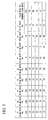
- (flow rate %) refers to the weight flow rate % of the gas, and the flow rate at each place is assumed to be 100 flow rate % in the case of the inlet guide vane 1 being opened to its maximum extent.
- FIG 3 is a table that shows the (flow rate %) at each position A to I in correspondence with the (flow rate %) of the gas supplied to the demand end device.
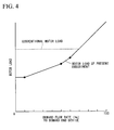
- FIG. 4 is a graph that shows the relationship between the demand flow amount to the demand end device and the motor load.
- A is the upstream side position of the inlet guide vane 1
- B is the position between the inlet guide vane 1 and the first centrifugal compressor
- C is the position between the centrifugal compressor 21 and the second centrifugal compressor
- D is the position on the downstream side of the second centrifugal compressor
- E is the position on the downstream side of the second centrifugal compressor 22 and the position after the removal of the gas to be exhausted via the exhaust control value 5
- F is the position on the downstream side of the second centrifugal compressor 22 and is the position that is divided to the side of the first circulation and supply control valve 3 and the second circulation and supply control valve 4
- G is the position on the downstream side of the of the exhaust control valve
- H is the position between the first circulation and supply control valve 3 and the first centrifugal compressor
- I is the position between the second circulation and supply control valve 4 and the second centrifugal compressor
- J is the position just before the demand end.
- the set value based on the surging limit of the first centrifugal compressor 21 is 60 flow rate %
- the set value based on the surging limit of the second centrifugal compressor 22 is 70 flow rate %.
- the inlet guide vane 1 is opened to a maximum, and thereby the flow rate at A to D becomes 100 flow rate %.
- the control unit 8 in the case of the demand flow rate of the demand end device being 100 flow rate %, makes the output of the motor 23 100% and puts the first circulation and supply control valve 3, the second circulation and supply control valve 4, and the exhaust control valve 5 in a closed state.
- the flow rate at E becomes 100 flow rate %
- the flow rates at F to I become 0 flow rate %. That is, in the case of the demand flow rate of the demand end device being 100 flow rate %, all of the gas is supplied to the demand end device, and there is no circulation and supply to the first centrifugal compressor 21 and the second centrifugal compressor 22.
- the load of the motor 23 also becomes 100% as shown in FIG. 4 .
- the control unit 8 restricts the opening of the inlet guide vane 1 to make the flow rate at A 70 flow rate %.
- the flow rate at B to D also becomes 70 flow rate %.
- the control unit 8 in the case of the demand flow rate of the demand end device being 70 flow rate %, puts the first circulation and supply control valve 3, the second circulation and supply control valve 4, and the exhaust control valve 5 in a closed state.
- the flow rate at E becomes 70 flow rate %
- the flow rate at F to I becomes 0 flow rate %. That is, in the case of the demand flow rate of the demand end device being 70 flow rate %, all of the gas is supplied to the demand end device, and there is no circulation and supply to the first centrifugal compressor 21 and the second centrifugal compressor 22.
- the load of the motor 23 also becomes 70% as shown in FIG 4 .
- the control unit 8 restricts the opening of the inlet guide vane 1 to make the flow rate at A 60 flow rate %.
- the control unit 8 opens up the second circulation and supply control valve 4 so that a 10 flow rate % portion of the gas that is discharged from the gas compression portion 2 is circulated and supplied to the second centrifugal compressor 22.
- the first circulation and supply control valve 3 and the exhaust control valve 5 remain closed.
- the flow rate at B and C becomes 60 flow rate %
- the flow rate at D and E becomes 70 flow rate %
- the flow rate at F and I becomes 10 flow rate %
- the flow rate at G and H becomes 0 flow rate %.
- the control unit 8 restricts the opening of the inlet guide vane 1 to make the flow rate at A 50 flow rate %.
- the control unit 8 opens up the first circulation and supply control valve 3 and the second circulation and supply control valve 4 so that, of the gas that is discharged from the gas compression portion 2, 10 flow rate % is circulated and supplied to the first centrifugal compressor 21 and a 10 flow rate % portion is circulated and supplied to the second centrifugal compressor 22.
- the exhaust control valve 5 remains closed.
- the flow rate at B becomes 50 flow rate %
- the flow rate at C becomes 60 flow rate %
- the flow rate at D and E becomes 70 flow rate %
- the flow rate at F becomes 20 flow rate %
- the flow rate at G becomes 0 flow rate %
- the flow rate at H and I becomes 10 flow rate %.
- the flow rate in the diffuser 21h becomes 60 flow rate %
- the flow rate in the diffuser 22h becomes 70 flow rate %, it is possible to suppress the occurrence of surging in the first centrifugal compressor 21 and the second centrifugal compressor 22.
- the load on the motor 23 is further reduced compared to the case of the demand flow rate of the demand end device being 60 flow rate % as shown in FIG. 4 .
- the control unit 8 restricts the opening of the inlet guide vane 1 to make the flow rate at A 10 flow rate %.
- the control unit 8 opens up the first circulation and supply control valve 3 and the second circulation and supply control valve 4 so that, of the gas that is discharged from the gas compression portion 2, 50 flow rate % is circulated and supplied to the first centrifugal compressor 21 and a 10 flow rate % portion is circulated and supplied to the second centrifugal compressor 22.
- the exhaust control valve 5 remains closed.
- the flow rate at B becomes 10 flow rate %
- the flow rate at C becomes 60 flow rate %
- the flow rate at D and E becomes 70 flow rate %
- the flow rate at F becomes 60 flow rate %
- the flow rate at G becomes 0 flow rate %
- the flow rate at H becomes 50 flow rate %
- the flow rate at I becomes 10 flow rate %.
- the flow rate in the diffuser 21h becomes 60 flow rate %
- the flow rate in the diffusers 22h becomes 70 flow rate %
- the load on the motor 23 is further reduced compared to the case of the demand flow rate of the demand end device being 50 flow rate % as shown in FIG 4 .
- the control unit 8 similarly to the case of the demand flow rate of the demand end device being 10 flow rate %, opens up the first circulation and supply control valve 3 and the second circulation and supply control valve 4 so that, of the gas that is discharged from the gas compression portion 2, 50 flow rate % is circulated and supplied to the first centrifugal compressor 21 and a 10 flow rate % portion is circulated and supplied to the second centrifugal compressor 22. Then, it is opened via the exhaust control valve 5, and the output of the motor 23 is maintained at 10%.
- the flow rate at B becomes 10 flow rate %
- the flow rate at C and E becomes 60 flow rate %
- the flow rate at D becomes 70 flow rate %
- the flow rate at F becomes 60 flow rate %
- the flow rate at G becomes 10 flow rate %
- the flow rate at H becomes 50 flow rate %
- the flow rate at I becomes 10 flow rate %.
- the circulation and supply of gas is started in stages from the second centrifugal compressor 22 that is positioned furthest downstream to the first centrifugal compressor 21 that is upstream.
- the flow rate of gas that the turbo compression device S draws in is controlled in proportion to the gas demand flow rate (demand amount) of the demand end device. That is, in the case of the gas demand flow rate of the demand end device having decreased, the flow rate of the gas that the turbo compression device S draws in is reduced in proportion to this amount of decrease.
- each centrifugal compressor 21 and 22 in the case of the flow rate of the gas that is drawn in falling below a set value that is set based on the surging limit in the centrifugal compressor 21 and 22, a portion of the gas that is discharged from the gas compression portion 2 in the centrifugal compressors 21 and 22 concerned is circulated and supplied to the diffusers 21h and 22h of the centrifugal compressors 21 and 22, respectively, so that surging is suppressed.
- the gas that is circulated and supplied flows to the diffusers 21h and 22h without being supplied to the impellers 21a and 22a. For this reason, it is possible to supply gas at a sufficient flow rate to the diffusers 21h and 22h without increasing the load on the impellers 21a and 22a, and it is possible to suppress the occurrence of surging without increasing the load on the motor. That is, however low the flow rate of the gas that is drawn into the first centrifugal compressor 21, it is possible to cause a flow of gas with a flow rate that enables suppression of surging to the diffusers 21h and 22h of the respective centrifugal compressors 21 and 22.
- the turbo compression device that compresses gas by the centrifugal compressors 21 and 22 that are arranged in a plurality in series in the flow direction of the gas, it is possible to reduce energy consumption by sufficiently reducing the load of the motor while suppressing the occurrence of surging in the centrifugal compressors 21 and 22.
- turbo compression device and the method of controlling the turbo compression device of the present embodiment in the case of the gas demand flow rate of the demand end device being zero, in addition to maintaining the drawing in of the gas in the gas compression portion 2, a portion of the gas that is discharged from the gas compression portion 2 (that gas that is not circulated and supplied among the gas that is discharged from the gas compression portion 2) is exhausted without supplying to the demand end device. For this reason, even in the case of the gas demand flow rate of the demand end device being zero, it is possible to maintain the operation of the turbo compression device S with minimal energy consumption without completing closing the inlet guide vane 1. Therefore, it is possible to reopen the supply quickly in the case of the supply of gas to the demand end device once again being required.
- a value that relates to the centrifugal compressor 21 and the centrifugal compressor 22 that is stored in advance in the control unit 8 is made a value that matches the flow rate at the surging limit in the centrifugal compressors 21 and 22 and a predetermined margin. For this reason, after imparting a margin to the flow rate of the surging limit, since the gas is circulated and supplied to the centrifugal compressors 21 and 22, it is possible to reliably suppress the occurrence of surging.
- the centrifugal compressor that is positioned on the downstream side with respect to the gas flow direction has a smaller flow rate coefficient
- gas is circulated and supplied first to the centrifugal compressor that is positioned on the downstream side.
- the margin in the set value that relates to the first centrifugal compressor 21 to be greater than the margin in the set value that relates to the second centrifugal compressor 22
- turbo compression device being provided with two centrifugal compressors.
- the present invention is not limited to this, and there may be three or more centrifugal compressors.
- a constitution may be adopted that circulates and supplies gas simultaneously to a number of centrifugal compressors.
- the circulation and supply of gas may be started in stages in the order of a centrifugal compressor X3 that is furthest downstream, a centrifugal compressor X2 that is mid stream, and a centrifugal compressor X1 that is furthest upstream, as shown in the schematic drawing of FIG.
- the circulation and supply may be simultaneously started to the centrifugal compressor X3 that is furthest downstream, the centrifugal compressor X2 that is mid stream, and the circulation and supply may be subsequently started to the centrifugal compressor X1 that is furthest upstream, and as shown in the schematic drawing of FIG 7 , the circulation and supply may be simultaneously started to the centrifugal compressor X2 that is mid stream and the centrifugal compressor X1 that is furthest upstream after starting the circulation and supply to the centrifugal compressor X3 that is furthest downstream.
- the pressure means that is furthest downstream has a small flow rate coefficient and enters a surge first, in any event the circulation and supply to the centrifugal compressor that is located on the downstream side is started first, and thereafter the circulation and supply to the centrifugal compressor that is located on the upstream side is started.
- the constitution was described of directly measuring the flow rate of the gas discharged from the gas compression portion 2 by the flow rate detector 6 and, based on this measurement result, the control unit 8 acquiring the demand amount of gas of the demand end device.
- the present invention is not limited to this, and in place of the flow rate detector 6, the current consumption or power consumption of the motor 23 may be measured, and thereby the flow rate of the gas discharged from the gas compression portion 2 may be indirectly measured. With such a constitution, it is possible to acquire the demand amount of gas of the demand end device based on the measurement result.
- the present invention is not limited thereto, and it is possible to use an axial flow compressor as the compression means of the present invention.
- the present invention is not limited thereto, and it is possible to use an engine, such as a diesel engine, or a turbine, such as a steam turbine, as the driving means of the present invention. In such a case, it is possible to acquire the demand amount of gas of the demand end device by detecting the engine or turbine torque in place of the flow rate detector 6.
- the constitution was described in which the rotational frequency of the motor 23 is constant.
- the present invention is not limited thereto, and for example the rotational frequency of the motor 23 may be changed in accordance with the intake amount of gas of the gas compression portion 2. In such a case, an inverter motor is often used as the motor 23.
- the constitution was described in which the diffusers 21h and 22h are disposed just after the impellers 21a and 22a, respectively, and the gas is circulated and supplied to the diffusers 21h and 22h.
- the present invention is not limited thereto, and for example, in the case of a throttle channel or the like existing between the impeller 21a and 22a and the diffuser 21h and 22h, it is possible to circulate and supply gas to the diffusers 21h and 22h, or between the diffusers 21h and 22h and the impellers 21a and 22a (that is, the throttle channel).
- the present invention can be applied to a multi-stage compressor with a single shaft and multiple stages, in which a plurality of centrifugal compressors are disposed in multiple stages on a single shaft, and a multi-stage compressor with multiple shafts and multiple stages, in which a centrifugal compressor is disposed on each shaft of the plurality of shafts via a gear type speed increasing mechanism.
- gas of the present invention for example it is possible to use air, nitrogen, oxygen, or carbon dioxide gas.
- the gas compression device and a method of controlling the gas compression device of the present invention while suppressing the occurrence of surging in a centrifugal compressor, it is possible to sufficiently reduce the load of a motor, and it is possible to reduce the consumption of energy.
Landscapes
- Engineering & Computer Science (AREA)
- Mechanical Engineering (AREA)
- General Engineering & Computer Science (AREA)
- Life Sciences & Earth Sciences (AREA)
- Sustainable Development (AREA)
- Physics & Mathematics (AREA)
- Geometry (AREA)
- Control Of Positive-Displacement Air Blowers (AREA)
- Structures Of Non-Positive Displacement Pumps (AREA)
Applications Claiming Priority (2)
| Application Number | Priority Date | Filing Date | Title |
|---|---|---|---|
| JP2007188093A JP2009024582A (ja) | 2007-07-19 | 2007-07-19 | ガス圧縮装置及びガス圧縮装置の制御方法 |
| PCT/JP2008/062268 WO2009011241A1 (ja) | 2007-07-19 | 2008-07-07 | ガス圧縮装置及びガス圧縮装置の制御方法 |
Publications (1)
| Publication Number | Publication Date |
|---|---|
| EP2180192A1 true EP2180192A1 (en) | 2010-04-28 |
Family
ID=40259579
Family Applications (1)
| Application Number | Title | Priority Date | Filing Date |
|---|---|---|---|
| EP08790929A Withdrawn EP2180192A1 (en) | 2007-07-19 | 2008-07-07 | Gas compression device and method of controlling gas compression device |
Country Status (5)
| Country | Link |
|---|---|
| EP (1) | EP2180192A1 (ja) |
| JP (1) | JP2009024582A (ja) |
| KR (1) | KR20100037122A (ja) |
| CN (1) | CN101755127A (ja) |
| WO (1) | WO2009011241A1 (ja) |
Cited By (2)
| Publication number | Priority date | Publication date | Assignee | Title |
|---|---|---|---|---|
| EP2687730A1 (en) * | 2011-03-17 | 2014-01-22 | Mitsubishi Heavy Industries, Ltd. | Scroll structure for centrifugal compressor |
| US9541094B2 (en) | 2010-12-28 | 2017-01-10 | Mitsubishi Heavy Industries, Ltd. | Scroll structure of centrifugal compressor |
Families Citing this family (7)
| Publication number | Priority date | Publication date | Assignee | Title |
|---|---|---|---|---|
| KR101350803B1 (ko) * | 2011-11-14 | 2014-01-15 | 대우조선해양 주식회사 | Lng운송선의 압축기 부하 제어용 모듈 및 이것을 이용한 제어방법 |
| KR101858648B1 (ko) * | 2012-12-07 | 2018-05-16 | 한화파워시스템 주식회사 | 다단 압축 시스템의 서지 제어 방법 |
| KR101864321B1 (ko) * | 2013-07-23 | 2018-07-04 | 한화파워시스템 주식회사 | 유체 압축기 제어 시스템 |
| US9382911B2 (en) * | 2013-11-14 | 2016-07-05 | Danfoss A/S | Two-stage centrifugal compressor with extended range and capacity control features |
| KR102518300B1 (ko) * | 2018-03-06 | 2023-04-05 | 한화파워시스템 주식회사 | 터보 압축기 |
| KR101986805B1 (ko) * | 2018-11-28 | 2019-06-07 | (주)대주기계 | 고속 고효율 터보 공기압축기의 동절기 운전제어방법 |
| KR102548667B1 (ko) * | 2021-05-12 | 2023-06-28 | 엘지전자 주식회사 | 터보 압축기 및 이를 제어하는 방법 |
Family Cites Families (8)
| Publication number | Priority date | Publication date | Assignee | Title |
|---|---|---|---|---|
| JPS57124096A (en) | 1981-01-27 | 1982-08-02 | Ishikawajima Harima Heavy Ind Co Ltd | Controller for multi-stage compressor |
| JPS58172494A (ja) | 1982-04-05 | 1983-10-11 | Ishikawajima Harima Heavy Ind Co Ltd | タ−ボ圧縮機の制御装置 |
| JPS5999196U (ja) | 1982-12-23 | 1984-07-04 | 石川島播磨重工業株式会社 | タ−ボ圧縮機の制御装置 |
| JPH0254400U (ja) * | 1988-10-12 | 1990-04-19 | ||
| JP2655431B2 (ja) * | 1989-03-31 | 1997-09-17 | 石川島播磨重工業株式会社 | 遠心圧縮機の定流量制御装置 |
| JPH08284892A (ja) * | 1995-04-10 | 1996-10-29 | Mitsubishi Heavy Ind Ltd | 遠心圧縮機のディフューザ |
| JP3975501B2 (ja) | 1997-03-17 | 2007-09-12 | 株式会社Ihi | 遠心圧縮機 |
| JP2005016464A (ja) * | 2003-06-27 | 2005-01-20 | Ishikawajima Harima Heavy Ind Co Ltd | 圧縮装置 |
-
2007
- 2007-07-19 JP JP2007188093A patent/JP2009024582A/ja active Pending
-
2008
- 2008-07-07 EP EP08790929A patent/EP2180192A1/en not_active Withdrawn
- 2008-07-07 KR KR1020107001953A patent/KR20100037122A/ko not_active Application Discontinuation
- 2008-07-07 WO PCT/JP2008/062268 patent/WO2009011241A1/ja active Application Filing
- 2008-07-07 CN CN200880025068.8A patent/CN101755127A/zh active Pending
Non-Patent Citations (1)
| Title |
|---|
| See references of WO2009011241A1 * |
Cited By (4)
| Publication number | Priority date | Publication date | Assignee | Title |
|---|---|---|---|---|
| US9541094B2 (en) | 2010-12-28 | 2017-01-10 | Mitsubishi Heavy Industries, Ltd. | Scroll structure of centrifugal compressor |
| EP2687730A1 (en) * | 2011-03-17 | 2014-01-22 | Mitsubishi Heavy Industries, Ltd. | Scroll structure for centrifugal compressor |
| EP2687730A4 (en) * | 2011-03-17 | 2014-12-17 | Mitsubishi Heavy Ind Ltd | VOLUTE STRUCTURE FOR CENTRIFUGAL COMPRESSOR |
| US9562541B2 (en) | 2011-03-17 | 2017-02-07 | Mitsubishi Heavy Industries, Ltd. | Scroll structure of centrifugal compressor |
Also Published As
| Publication number | Publication date |
|---|---|
| WO2009011241A1 (ja) | 2009-01-22 |
| CN101755127A (zh) | 2010-06-23 |
| KR20100037122A (ko) | 2010-04-08 |
| JP2009024582A (ja) | 2009-02-05 |
Similar Documents
| Publication | Publication Date | Title |
|---|---|---|
| EP2180192A1 (en) | Gas compression device and method of controlling gas compression device | |
| EP1704330B1 (en) | Recirculation port | |
| EP2863032B1 (en) | Centrifugal compressor | |
| US9447753B2 (en) | Blow-by gas ventilation device | |
| JPS62178799A (ja) | 遠心圧縮機 | |
| WO2007095537A1 (en) | Multi-stage compression system and method of operating the same | |
| RU2575837C2 (ru) | Устройство и способ для уменьшения массового расхода воздуха для сгорания с низкими выбросами в расширенном диапазоне для одновальных газовых турбин | |
| CN107269392A (zh) | 用于调整燃气涡轮发动机中气流畸变的阀式气流通道组件 | |
| KR101863336B1 (ko) | 작동기, 작동기를 제어하기 위한 방법 및 작동기 용 제어 시스템 | |
| JP2012052508A (ja) | 可変過給機及び可変過給機の制御方法 | |
| JP2012149588A (ja) | 内燃機関の制御装置 | |
| CN110159564A (zh) | 一种低比转速的轴流风机 | |
| JP2009270467A (ja) | 遠心式圧縮機 | |
| US9574572B2 (en) | Compressor control method and system | |
| CN110454411A (zh) | 带有叶角可调风扇的压气机 | |
| WO2020196504A1 (ja) | 圧縮機システム | |
| US11499472B2 (en) | Electric multiple stage variable forced air induction system | |
| CN112443515A (zh) | 具有用于流动再循环的带端口护罩和噪声衰减器的压缩机以及包含该压缩机的涡轮增压器 | |
| CN205206951U (zh) | 一种增压内燃机压气机叶片冷却装置 | |
| US9915270B2 (en) | Turbocharger compressor with an elliptical diffuser wall | |
| CN211778224U (zh) | 一种两段式扩压器 | |
| CN114635876B (zh) | 一种带有引气机构的离心式压气机及涡轮增压器 | |
| JP2010180859A (ja) | 多段ターボ圧縮機 | |
| JPH10331792A (ja) | 遠心圧縮機吸込部の構造 | |
| JP2003322097A (ja) | 流体機械の流量制御方法 |
Legal Events
| Date | Code | Title | Description |
|---|---|---|---|
| PUAI | Public reference made under article 153(3) epc to a published international application that has entered the european phase |
Free format text: ORIGINAL CODE: 0009012 |
|
| STAA | Information on the status of an ep patent application or granted ep patent |
Free format text: STATUS: THE APPLICATION HAS BEEN WITHDRAWN |
|
| 17P | Request for examination filed |
Effective date: 20100211 |
|
| AK | Designated contracting states |
Kind code of ref document: A1 Designated state(s): AT BE BG CH CY CZ DE DK EE ES FI FR GB GR HR HU IE IS IT LI LT LU LV MC MT NL NO PL PT RO SE SI SK TR |
|
| AX | Request for extension of the european patent |
Extension state: AL BA MK RS |
|
| 18W | Application withdrawn |
Effective date: 20100414 |