EP2178595B1 - Vorrichtung zur verabreichung eines gefässimplantats mit geringer reibung - Google Patents
Vorrichtung zur verabreichung eines gefässimplantats mit geringer reibung Download PDFInfo
- Publication number
- EP2178595B1 EP2178595B1 EP08838108.2A EP08838108A EP2178595B1 EP 2178595 B1 EP2178595 B1 EP 2178595B1 EP 08838108 A EP08838108 A EP 08838108A EP 2178595 B1 EP2178595 B1 EP 2178595B1
- Authority
- EP
- European Patent Office
- Prior art keywords
- outer sheath
- sheath
- implant
- vascular implant
- longitudinal
- Prior art date
- Legal status (The legal status is an assumption and is not a legal conclusion. Google has not performed a legal analysis and makes no representation as to the accuracy of the status listed.)
- Not-in-force
Links
- 239000007943 implant Substances 0.000 title claims description 114
- 230000002792 vascular Effects 0.000 title claims description 85
- 239000000835 fiber Substances 0.000 claims description 39
- 239000000314 lubricant Substances 0.000 claims description 14
- 238000000034 method Methods 0.000 claims description 13
- 239000000463 material Substances 0.000 claims description 8
- 239000011800 void material Substances 0.000 claims description 8
- 238000004519 manufacturing process Methods 0.000 claims description 2
- 238000002399 angioplasty Methods 0.000 description 9
- 210000000748 cardiovascular system Anatomy 0.000 description 7
- 238000001990 intravenous administration Methods 0.000 description 6
- 229940000032 cardiovascular system drug Drugs 0.000 description 4
- 238000000576 coating method Methods 0.000 description 3
- 238000005461 lubrication Methods 0.000 description 3
- FAPWRFPIFSIZLT-UHFFFAOYSA-M Sodium chloride Chemical compound [Na+].[Cl-] FAPWRFPIFSIZLT-UHFFFAOYSA-M 0.000 description 2
- 239000011248 coating agent Substances 0.000 description 2
- 238000001125 extrusion Methods 0.000 description 2
- 239000012530 fluid Substances 0.000 description 2
- 238000002594 fluoroscopy Methods 0.000 description 2
- 230000001788 irregular Effects 0.000 description 2
- 230000036760 body temperature Effects 0.000 description 1
- 230000001419 dependent effect Effects 0.000 description 1
- 229910003460 diamond Inorganic materials 0.000 description 1
- 239000010432 diamond Substances 0.000 description 1
- 239000000843 powder Substances 0.000 description 1
- ITRNXVSDJBHYNJ-UHFFFAOYSA-N tungsten disulfide Chemical compound S=[W]=S ITRNXVSDJBHYNJ-UHFFFAOYSA-N 0.000 description 1
Images





Classifications
-
- A—HUMAN NECESSITIES
- A61—MEDICAL OR VETERINARY SCIENCE; HYGIENE
- A61F—FILTERS IMPLANTABLE INTO BLOOD VESSELS; PROSTHESES; DEVICES PROVIDING PATENCY TO, OR PREVENTING COLLAPSING OF, TUBULAR STRUCTURES OF THE BODY, e.g. STENTS; ORTHOPAEDIC, NURSING OR CONTRACEPTIVE DEVICES; FOMENTATION; TREATMENT OR PROTECTION OF EYES OR EARS; BANDAGES, DRESSINGS OR ABSORBENT PADS; FIRST-AID KITS
- A61F2/00—Filters implantable into blood vessels; Prostheses, i.e. artificial substitutes or replacements for parts of the body; Appliances for connecting them with the body; Devices providing patency to, or preventing collapsing of, tubular structures of the body, e.g. stents
- A61F2/95—Instruments specially adapted for placement or removal of stents or stent-grafts
-
- A—HUMAN NECESSITIES
- A61—MEDICAL OR VETERINARY SCIENCE; HYGIENE
- A61F—FILTERS IMPLANTABLE INTO BLOOD VESSELS; PROSTHESES; DEVICES PROVIDING PATENCY TO, OR PREVENTING COLLAPSING OF, TUBULAR STRUCTURES OF THE BODY, e.g. STENTS; ORTHOPAEDIC, NURSING OR CONTRACEPTIVE DEVICES; FOMENTATION; TREATMENT OR PROTECTION OF EYES OR EARS; BANDAGES, DRESSINGS OR ABSORBENT PADS; FIRST-AID KITS
- A61F2/00—Filters implantable into blood vessels; Prostheses, i.e. artificial substitutes or replacements for parts of the body; Appliances for connecting them with the body; Devices providing patency to, or preventing collapsing of, tubular structures of the body, e.g. stents
- A61F2/01—Filters implantable into blood vessels
-
- A—HUMAN NECESSITIES
- A61—MEDICAL OR VETERINARY SCIENCE; HYGIENE
- A61F—FILTERS IMPLANTABLE INTO BLOOD VESSELS; PROSTHESES; DEVICES PROVIDING PATENCY TO, OR PREVENTING COLLAPSING OF, TUBULAR STRUCTURES OF THE BODY, e.g. STENTS; ORTHOPAEDIC, NURSING OR CONTRACEPTIVE DEVICES; FOMENTATION; TREATMENT OR PROTECTION OF EYES OR EARS; BANDAGES, DRESSINGS OR ABSORBENT PADS; FIRST-AID KITS
- A61F2/00—Filters implantable into blood vessels; Prostheses, i.e. artificial substitutes or replacements for parts of the body; Appliances for connecting them with the body; Devices providing patency to, or preventing collapsing of, tubular structures of the body, e.g. stents
- A61F2/82—Devices providing patency to, or preventing collapsing of, tubular structures of the body, e.g. stents
- A61F2/86—Stents in a form characterised by the wire-like elements; Stents in the form characterised by a net-like or mesh-like structure
- A61F2/90—Stents in a form characterised by the wire-like elements; Stents in the form characterised by a net-like or mesh-like structure characterised by a net-like or mesh-like structure
- A61F2/91—Stents in a form characterised by the wire-like elements; Stents in the form characterised by a net-like or mesh-like structure characterised by a net-like or mesh-like structure made from perforated sheets or tubes, e.g. perforated by laser cuts or etched holes
- A61F2/915—Stents in a form characterised by the wire-like elements; Stents in the form characterised by a net-like or mesh-like structure characterised by a net-like or mesh-like structure made from perforated sheets or tubes, e.g. perforated by laser cuts or etched holes with bands having a meander structure, adjacent bands being connected to each other
-
- A—HUMAN NECESSITIES
- A61—MEDICAL OR VETERINARY SCIENCE; HYGIENE
- A61F—FILTERS IMPLANTABLE INTO BLOOD VESSELS; PROSTHESES; DEVICES PROVIDING PATENCY TO, OR PREVENTING COLLAPSING OF, TUBULAR STRUCTURES OF THE BODY, e.g. STENTS; ORTHOPAEDIC, NURSING OR CONTRACEPTIVE DEVICES; FOMENTATION; TREATMENT OR PROTECTION OF EYES OR EARS; BANDAGES, DRESSINGS OR ABSORBENT PADS; FIRST-AID KITS
- A61F2/00—Filters implantable into blood vessels; Prostheses, i.e. artificial substitutes or replacements for parts of the body; Appliances for connecting them with the body; Devices providing patency to, or preventing collapsing of, tubular structures of the body, e.g. stents
- A61F2/95—Instruments specially adapted for placement or removal of stents or stent-grafts
- A61F2/962—Instruments specially adapted for placement or removal of stents or stent-grafts having an outer sleeve
-
- A—HUMAN NECESSITIES
- A61—MEDICAL OR VETERINARY SCIENCE; HYGIENE
- A61F—FILTERS IMPLANTABLE INTO BLOOD VESSELS; PROSTHESES; DEVICES PROVIDING PATENCY TO, OR PREVENTING COLLAPSING OF, TUBULAR STRUCTURES OF THE BODY, e.g. STENTS; ORTHOPAEDIC, NURSING OR CONTRACEPTIVE DEVICES; FOMENTATION; TREATMENT OR PROTECTION OF EYES OR EARS; BANDAGES, DRESSINGS OR ABSORBENT PADS; FIRST-AID KITS
- A61F2/00—Filters implantable into blood vessels; Prostheses, i.e. artificial substitutes or replacements for parts of the body; Appliances for connecting them with the body; Devices providing patency to, or preventing collapsing of, tubular structures of the body, e.g. stents
- A61F2/01—Filters implantable into blood vessels
- A61F2/011—Instruments for their placement or removal
-
- A—HUMAN NECESSITIES
- A61—MEDICAL OR VETERINARY SCIENCE; HYGIENE
- A61F—FILTERS IMPLANTABLE INTO BLOOD VESSELS; PROSTHESES; DEVICES PROVIDING PATENCY TO, OR PREVENTING COLLAPSING OF, TUBULAR STRUCTURES OF THE BODY, e.g. STENTS; ORTHOPAEDIC, NURSING OR CONTRACEPTIVE DEVICES; FOMENTATION; TREATMENT OR PROTECTION OF EYES OR EARS; BANDAGES, DRESSINGS OR ABSORBENT PADS; FIRST-AID KITS
- A61F2/00—Filters implantable into blood vessels; Prostheses, i.e. artificial substitutes or replacements for parts of the body; Appliances for connecting them with the body; Devices providing patency to, or preventing collapsing of, tubular structures of the body, e.g. stents
- A61F2/82—Devices providing patency to, or preventing collapsing of, tubular structures of the body, e.g. stents
- A61F2/86—Stents in a form characterised by the wire-like elements; Stents in the form characterised by a net-like or mesh-like structure
- A61F2/90—Stents in a form characterised by the wire-like elements; Stents in the form characterised by a net-like or mesh-like structure characterised by a net-like or mesh-like structure
- A61F2/91—Stents in a form characterised by the wire-like elements; Stents in the form characterised by a net-like or mesh-like structure characterised by a net-like or mesh-like structure made from perforated sheets or tubes, e.g. perforated by laser cuts or etched holes
-
- A—HUMAN NECESSITIES
- A61—MEDICAL OR VETERINARY SCIENCE; HYGIENE
- A61F—FILTERS IMPLANTABLE INTO BLOOD VESSELS; PROSTHESES; DEVICES PROVIDING PATENCY TO, OR PREVENTING COLLAPSING OF, TUBULAR STRUCTURES OF THE BODY, e.g. STENTS; ORTHOPAEDIC, NURSING OR CONTRACEPTIVE DEVICES; FOMENTATION; TREATMENT OR PROTECTION OF EYES OR EARS; BANDAGES, DRESSINGS OR ABSORBENT PADS; FIRST-AID KITS
- A61F2/00—Filters implantable into blood vessels; Prostheses, i.e. artificial substitutes or replacements for parts of the body; Appliances for connecting them with the body; Devices providing patency to, or preventing collapsing of, tubular structures of the body, e.g. stents
- A61F2/95—Instruments specially adapted for placement or removal of stents or stent-grafts
- A61F2/9517—Instruments specially adapted for placement or removal of stents or stent-grafts handle assemblies therefor
-
- A—HUMAN NECESSITIES
- A61—MEDICAL OR VETERINARY SCIENCE; HYGIENE
- A61F—FILTERS IMPLANTABLE INTO BLOOD VESSELS; PROSTHESES; DEVICES PROVIDING PATENCY TO, OR PREVENTING COLLAPSING OF, TUBULAR STRUCTURES OF THE BODY, e.g. STENTS; ORTHOPAEDIC, NURSING OR CONTRACEPTIVE DEVICES; FOMENTATION; TREATMENT OR PROTECTION OF EYES OR EARS; BANDAGES, DRESSINGS OR ABSORBENT PADS; FIRST-AID KITS
- A61F2/00—Filters implantable into blood vessels; Prostheses, i.e. artificial substitutes or replacements for parts of the body; Appliances for connecting them with the body; Devices providing patency to, or preventing collapsing of, tubular structures of the body, e.g. stents
- A61F2/82—Devices providing patency to, or preventing collapsing of, tubular structures of the body, e.g. stents
- A61F2/86—Stents in a form characterised by the wire-like elements; Stents in the form characterised by a net-like or mesh-like structure
- A61F2/90—Stents in a form characterised by the wire-like elements; Stents in the form characterised by a net-like or mesh-like structure characterised by a net-like or mesh-like structure
- A61F2/91—Stents in a form characterised by the wire-like elements; Stents in the form characterised by a net-like or mesh-like structure characterised by a net-like or mesh-like structure made from perforated sheets or tubes, e.g. perforated by laser cuts or etched holes
- A61F2/915—Stents in a form characterised by the wire-like elements; Stents in the form characterised by a net-like or mesh-like structure characterised by a net-like or mesh-like structure made from perforated sheets or tubes, e.g. perforated by laser cuts or etched holes with bands having a meander structure, adjacent bands being connected to each other
- A61F2002/9155—Adjacent bands being connected to each other
- A61F2002/91558—Adjacent bands being connected to each other connected peak to peak
-
- A—HUMAN NECESSITIES
- A61—MEDICAL OR VETERINARY SCIENCE; HYGIENE
- A61F—FILTERS IMPLANTABLE INTO BLOOD VESSELS; PROSTHESES; DEVICES PROVIDING PATENCY TO, OR PREVENTING COLLAPSING OF, TUBULAR STRUCTURES OF THE BODY, e.g. STENTS; ORTHOPAEDIC, NURSING OR CONTRACEPTIVE DEVICES; FOMENTATION; TREATMENT OR PROTECTION OF EYES OR EARS; BANDAGES, DRESSINGS OR ABSORBENT PADS; FIRST-AID KITS
- A61F2230/00—Geometry of prostheses classified in groups A61F2/00 - A61F2/26 or A61F2/82 or A61F9/00 or A61F11/00 or subgroups thereof
- A61F2230/0002—Two-dimensional shapes, e.g. cross-sections
- A61F2230/0028—Shapes in the form of latin or greek characters
- A61F2230/005—Rosette-shaped, e.g. star-shaped
-
- A—HUMAN NECESSITIES
- A61—MEDICAL OR VETERINARY SCIENCE; HYGIENE
- A61F—FILTERS IMPLANTABLE INTO BLOOD VESSELS; PROSTHESES; DEVICES PROVIDING PATENCY TO, OR PREVENTING COLLAPSING OF, TUBULAR STRUCTURES OF THE BODY, e.g. STENTS; ORTHOPAEDIC, NURSING OR CONTRACEPTIVE DEVICES; FOMENTATION; TREATMENT OR PROTECTION OF EYES OR EARS; BANDAGES, DRESSINGS OR ABSORBENT PADS; FIRST-AID KITS
- A61F2230/00—Geometry of prostheses classified in groups A61F2/00 - A61F2/26 or A61F2/82 or A61F9/00 or A61F11/00 or subgroups thereof
- A61F2230/0002—Two-dimensional shapes, e.g. cross-sections
- A61F2230/0028—Shapes in the form of latin or greek characters
- A61F2230/0054—V-shaped
-
- A—HUMAN NECESSITIES
- A61—MEDICAL OR VETERINARY SCIENCE; HYGIENE
- A61F—FILTERS IMPLANTABLE INTO BLOOD VESSELS; PROSTHESES; DEVICES PROVIDING PATENCY TO, OR PREVENTING COLLAPSING OF, TUBULAR STRUCTURES OF THE BODY, e.g. STENTS; ORTHOPAEDIC, NURSING OR CONTRACEPTIVE DEVICES; FOMENTATION; TREATMENT OR PROTECTION OF EYES OR EARS; BANDAGES, DRESSINGS OR ABSORBENT PADS; FIRST-AID KITS
- A61F2230/00—Geometry of prostheses classified in groups A61F2/00 - A61F2/26 or A61F2/82 or A61F9/00 or A61F11/00 or subgroups thereof
- A61F2230/0063—Three-dimensional shapes
- A61F2230/0067—Three-dimensional shapes conical
-
- A—HUMAN NECESSITIES
- A61—MEDICAL OR VETERINARY SCIENCE; HYGIENE
- A61F—FILTERS IMPLANTABLE INTO BLOOD VESSELS; PROSTHESES; DEVICES PROVIDING PATENCY TO, OR PREVENTING COLLAPSING OF, TUBULAR STRUCTURES OF THE BODY, e.g. STENTS; ORTHOPAEDIC, NURSING OR CONTRACEPTIVE DEVICES; FOMENTATION; TREATMENT OR PROTECTION OF EYES OR EARS; BANDAGES, DRESSINGS OR ABSORBENT PADS; FIRST-AID KITS
- A61F2230/00—Geometry of prostheses classified in groups A61F2/00 - A61F2/26 or A61F2/82 or A61F9/00 or A61F11/00 or subgroups thereof
- A61F2230/0063—Three-dimensional shapes
- A61F2230/0073—Quadric-shaped
- A61F2230/008—Quadric-shaped paraboloidal
Definitions
- the present disclosure relates generally to surgical devices. More specifically, the present disclosure relates to vascular implant delivery devices.
- Vascular implants can include stents, stent grafts, intravenous filters, etc.
- Other vascular treatment devices can include angioplasty balloons, etc.
- these implants and devices can be delivered to a location within a patient using a catheter.
- the catheter is moved into a predetermined location within the cardiovascular system of a patient. Then, the implant or device can be moved through the catheter and expelled, or otherwise expressed, from the catheter to the targeted location.
- a vascular implant delivery device includes a body and a syringe attachment formed in the body. Further, the device includes an outer sheath extending from the body. The outer sheath includes a distal end that can be configured to receive a vascular implant. The device also includes at least three implant support structures that extend radially inward from the distal end of the outer sheath. The implant support structures are configured to support and guide a vascular implant moving through the outer sheath. Additionally, the device includes an inner carrier catheter slidably disposed within the outer sheath.
- the vascular implant delivery device can include at least three longitudinal fibers partially embedded within the outer sheath. Each longitudinal fiber at least partially extends radially into the lumen of the outer sheath.
- a method of making an outer sheath includes installing a plurality of fibers in a mandrel having an outer periphery.
- the fibers extend along a length of the mandrel and extend radially outward beyond the outer periphery of the mandrel.
- the method also includes forming a material around the mandrel in a generally tubular shape to form an outer sheath.
- the material of the outer sheath partially encompasses each of the plurality of fibers.
- a method of delivering a vascular implant to a patient includes moving an outer sheath to a target area wherein the vascular implant is located within the outer sheath, commencing delivery of a lubricant through the outer sheath wherein the lubricant flows at least partially around the vascular implant, and expelling the vascular implant from the outer sheath.
- a stent delivery device is shown and is generally designated 100.
- the stent delivery device 100 includes a body 102 having a proximal end 104 and a distal end 106.
- a first syringe attachment 108 can be formed in the body 102 between the proximal end 104 and the distal end 106.
- the first syringe attachment 108 can be a Luer syringe attachment.
- the first syringe attachment 108 provides fluid communication to a lumen formed within an outer sheath 110, described below.
- FIG. 1 indicates that the stent delivery device 100 includes an outer sheath 110.
- the outer sheath 110 includes a proximal end 112 and a distal end 114. Further, the outer sheath 110 extends from the distal end 106 of the body 102 of the stent delivery device 100. In particular, the proximal end 112 of the outer sheath 110 is attached to the distal end 106 of the body 102 of the stent delivery device 100.
- the distal end 114 of the outer sheath 110 is relatively soft and rounded.
- the outer sheath 110 includes a lumen 116 formed therein. Further, the distal end 114 of the outer sheath 110 includes a radiopaque band 118.
- the stent delivery device 100 further includes an inner carrier catheter 120 slidably disposed within the outer sheath 110.
- the inner carrier catheter 120 can extend through the body 102 of the stent delivery device 100 and into the lumen 116 formed in the outer sheath 110.
- the inner carrier catheter 120 can be coaxial with the outer sheath 110.
- the inner carrier catheter 120 can include a proximal end 122 and a distal end 124.
- the inner carrier catheter 120 can be formed with a lumen (not shown) that can be sized to fit over a guide wire.
- the lumen of the inner carrier catheter 120 can fit over a 0.035 inch (approximately 0.89 mm) guide wire.
- a stent 126 can be compressed between the inner catheter 120, e.g., the distal end of the inner catheter 120, and the outer sheath 110.
- a handle 128 can be attached to, or otherwise extend from, the proximal end 122 of the inner carrier catheter 120.
- the handle 128 can include a proximal end 130 and a distal end 132.
- the proximal end 130 of the handle 128 can include a second syringe attachment 134.
- the second syringe attachment 134 can be a Luer syringe attachment.
- the second syringe attachment 134 can provide fluid communication with the lumen formed within the inner carrier catheter 120.
- the stent delivery device 100 can also include a safety clip 140 installed between the body 102 of the stent delivery device 100 and the handle 128 of the inner carrier catheter 120.
- the safety clip 140 can include a proximal end 142 and a distal end 144. Further, the safety clip 140 can include a butterfly handle 146 between the proximal end 142 of the safety clip 140 and the distal end 144 of the safety clip 140.
- the safety clip 140 can be installed between the body 102 of the stent delivery device 100 and the handle 128 of the inner carrier catheter 120 such that the proximal end 142 of the safety clip 140 abuts the distal end 132 of the handle 128 and the distal end 144 of the safety clip 140 abuts the proximal end 104 of the body 102.
- the safety clip 140 can fit over the inner carrier catheter 120. Further, the safety clip 140 can prevent the body 102 of the stent delivery device 100 from moving relative to the handle 128 of the inner carrier catheter 120. Further, the safety clip 140 can prevent the outer sheath 110 from sliding relative to the inner carrier catheter 120.
- the stent delivery device 100 can be threaded into a cardiovascular system of a patient to a target area.
- the radio opaque band 118 formed on the outer sheath 110 can be used to guide the stent delivery device into the cardiovascular system of a patient, e.g., with the aid of fluoroscopy. Further, a pair of radiopaque bands on the stent 126 can aid in positioning the stent 126 within the patient.
- the butterfly handle 146 can be squeezed in order to remove the safety clip 140 from the inner carrier catheter 120 and the stent delivery device 100. Thereafter, the body 102 of the stent delivery device 100 can be moved toward the handle of the inner carrier catheter 120 in order to slide the outer sheath 110 off of the stent 126 and expose the stent 126 inside the patient.
- body temperature will allow the stent 126 to move to a shape memory configuration, e.g., an expanded configuration, within the patient, and be deployed within the patient.
- the inner carrier catheter 120 can be withdrawn from the patient.
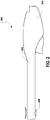
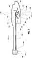
- FIG. 2 and FIG. 3 illustrate a handle assembly, generally designated 200 that can be used in conjunction with the stent delivery system 100, described above.
- the handle assembly 200 can include a housing 202.
- the housing 202 can be hollow and can include a proximal end 204 and a distal end 206.
- a rail support structure 208 can be disposed within the housing 202 near the proximal end 204 of the housing 202.
- a pair of rails 210 can extend between the distal end 206 of the housing 202 and the rail support structure 208.
- the handle assembly 200 can also include a carrier 212 that can be slidably disposed on the rails 210.
- the carrier 212 can be configured to receive the body of a stent delivery system, e.g., the stent delivery system 100, described above.
- a shaft 214 can extend from the housing 202 near the rail support structure 208, e.g., between the rail support structure 208 and the distal end 206 of the housing 202.
- the shaft 214 is substantially perpendicular to the rails 210.
- a ratchet wheel 216 can be rotatably disposed on the shaft 214.
- the ratchet wheel 216 can be formed with a plurality of teeth 218 around the outer periphery of the ratchet wheel 216.
- the handle assembly 200 can also include a pawl 220 extending from the rail support structure 208.
- the pawl 220 can be configured to engage the ratchet wheel 216, e.g., the teeth 218 of the ratchet wheel 216, and permit rotation of the ratchet wheel 216 in a single direction, e.g., clockwise.
- FIG. 3 further shows that the handle assembly 200 can include a cable 222.
- the cable 222 can include a proximal end 224 and a distal end 226.
- the cable 222 can extend within the housing along the length of the rails 210.
- the proximal end 224 of the cable 222 can be wrapped, or otherwise disposed, around the ratchet wheel 216.
- the distal end 226 of the cable 222 can be attached, or otherwise affixed, to the carrier 212.
- the ratchet wheel 216 is rotated, the cable 222 can be rolled onto the ratchet wheel 216 and the carrier 212 can slide along the rails 210 toward the proximal end 204 of the housing 202.
- the handle assembly 200 can also include a trigger 228 extending from the housing 202.
- the trigger 228 can include a proximal end 230 and a distal end 232.
- the proximal end 230 of the trigger 228 can be rotatably engaged with the housing 202 and the distal end 232 of the trigger 228 can be free. As such, the trigger 228 can rotate around the proximal end 230 of the trigger 228.
- FIG. 3 further indicates that an arm 234 can extend from the trigger 228.
- the arm 234 can include a plurality of teeth 236 that can engage the teeth 218 formed on the ratchet wheel 216.
- the handle assembly 200 can also include a spring 238 installed around a post 240 within the housing 202. The spring 238 can bias the trigger 228 outward relative to the housing 202.
- the arm 234 can rotate the ratchet wheel 216 and cause the carrier 212 to slide within the housing 202 toward the proximal end 204 of the housing 202.
- the stent delivery device 100 can be engaged with the handle assembly 200 as shown in FIG. 4 .
- the body 102 of the stent delivery device 100 can be inserted within the carrier 212.
- the inner carrier catheter 120 can be installed within the housing 202 of the handle assembly 200 so that the handle 128 of the inner carrier catheter 120 extends through the proximal end 204 of the housing 202.
- the handle 128 of the inner carrier catheter 120 can be engaged with the housing 202 so that the handle 128 does not move relative to the housing during operation of the handle assembly 200.
- the safety clip 140 can be removed from the stent delivery device 100 and the trigger 228 can be squeezed to move the carrier 212 within the handle assembly 200 toward the proximal end 204 of the housing 202.
- the body 102 of the stent delivery device 100 can be moved toward the handle 128 of the inner carrier catheter 120.
- the outer sheath 110 can slide off of the stent 126 and expose the stent 126 inside a patient.
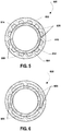
- a sheath is shown and is generally designated 500.
- the sheath 500 is shown in cross-section. Further, the sheath 500 can be used as an outer sheath in conjunction with a vascular implant delivery device, e.g., the vascular implant delivery device 100 shown in FIG. 1 through FIG. 4 .
- the sheath 500 can include an outer surface 502 and an inner surface 504.
- a plurality of internal longitudinal voids 506 can be formed in sheath 500.
- the internal longitudinal voids 506 can extend into the inner surface 504 of the sheath 500.
- the internal longitudinal voids 506 can be equally spaced around the inner surface 504 of the sheath 500.
- the sheath 500 includes a plurality of implant support structures 508.
- each implant support structure 508 is formed between adjacent longitudinal voids 506 formed in the sheath 500.
- the implant support structures 508 are equally spaced around the inner surface 504 of the sheath 500.
- the support structures 508 can be shaped as shown. However, the support structures 508 can be shaped otherwise, e.g., circular, rectangular, triangular, irregular, etc.
- a vascular implant 510 is slidably disposed within the sheath 500.
- the vascular implant 510 can be a stent, a stent graft, an intravenous filter, or some other implant that is delivered to a patient using a cannulated delivery device.
- the vascular implant 510 can be an angioplasty balloon that is temporarily deployed and inflated to treat a patient.
- FIG. 5 indicates that the vascular implant 510 can include an outer surface 512.
- each longitudinal void 506 acts as a longitudinal channel for a lubricant 514 introduced into the sheath 500 around the vascular implant 510.
- the lubricant can be saline solution.
- FIG. 5 indicates that each longitudinal void 506 can be at least partially filled with the lubricant and the lubricant can surround the vascular implant 510. The lubricant can reduce friction between the implant support structures 508 and the vascular implant 510. As such, the force require to expel the vascular implant 510 from the sheath is substantially reduced.
- FIG. 5 twelve longitudinal voids 506 and twelve implant support structures 508 can be formed in sheath 500.
- some other number of longitudinal voids can be formed in the inner surface.
- FIG. 6 shows a second embodiment of a sheath 600 that is formed with six longitudinal voids 606 and six implant support structures 608.
- FIG. 7 shows a third embodiment of a sheath 700 that is formed with three longitudinal voids 706 and three implant support structures 708.
- the sheath can contact a portion of the outer surface 512 of the vascular implant 510.
- the sheath 500 does not contact more than fifty percent (50%) of the outer surface 512 of the vascular implant 510. In another embodiment, the sheath 500 does not contact more than thirty-five percent (35%) of the outer surface 512 of the vascular implant 510. In another embodiment, the sheath 500 does not contact more than thirty percent (30%) of the outer surface 512 of the vascular implant 510. In yet another embodiment, the sheath 500 does not contact more than twenty-five percent (25%) of the outer surface 512 of the vascular implant 510. In still another embodiment, the sheath 500 does not contact more than twenty percent (20%) of the outer surface 512 of the vascular implant 510.
- the sheath 500 does not contact more than fifteen percent (15%) of the outer surface 512 of the vascular implant 510. In another embodiment, the sheath 500 does not contact more than ten percent (10%) of the outer surface 512 of the vascular implant 510. In another embodiment, the sheath 500 contacts at least five percent (5%) of the outer surface 512 of the vascular implant 510.
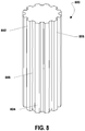
- FIG. 8 depicts an example of a mandrel, generally designated 800, on which a sheath can be formed, e.g., the sheath depicted in FIG. 5 .
- the mandrel 800 includes a proximal end 802 and a distal end 804.
- the mandrel 800 also includes an outer periphery 806.
- the outer periphery 806 of the mandrel 800 is formed with a plurality of longitudinal voids 808 radially spaced therearound.
- material is formed around the mandrel 800 and cured.
- the interior of a sheath formed on the mandrel takes the form of the mandrel.
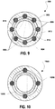
- a fourth embodiment of a sheath is shown and is generally designated 900.
- the sheath 900 is shown in cross-section. Further, the sheath 900 can be used as an outer sheath in conjunction with a vascular implant delivery device, e.g., the vascular implant delivery device 100 shown in FIG. 1 through FIG. 4 .
- the sheath 900 includes an outer surface 902 and an inner surface 904.
- the sheath 900 also includes a lumen that is bound by the inner surface 904.
- the sheath 900 includes a plurality of longitudinal fibers 906 that extend longitudinally along a length of the sheath 900.
- the fibers 906 can be shaped as shown. However, the fibers 906 can be shaped otherwise, e.g., rectangular, triangular, irregular, etc. Further, the fibers 906 can be lubricious or coated with a lubricious coating. Additionally, the fibers 906 can extend in a non-linear fashion along the length of the sheath 900. For example, the fibers 906 can extend helically along the length of the sheath 900 and the fibers 906 can cross each other at various locations along the length of the sheath 900.
- Each longitudinal fiber 906 can extend radially from the inner surface 904 into the lumen of the sheath 900 so that only a portion of each longitudinal fiber 906 is embedded within the sheath 900. For example, at least fifty percent (50%) of each longitudinal fiber is embedded within the sheath 900. In another embodiment, at least fifty-five percent (55%) of each longitudinal fiber is embedded within the sheath 900. In yet another embodiment, at least sixty percent (60%) of each longitudinal fiber is embedded within the sheath 900. In still another embodiment, at least sixty-five percent (65%) of each longitudinal fiber is embedded within the sheath 900. In another embodiment, at least seventy percent (70%) of each longitudinal fiber is embedded within the sheath 900. In yet another embodiment, not more than eighty-five percent (85%) of each longitudinal fiber is embedded within the sheath 900.
- each longitudinal void 908 is formed between adjacent longitudinal fibers 906, i.e., between the portions of the longitudinal fibers 906 that extend from the inner surface 904 of the sheath 900.
- the longitudinal voids 908 are equally spaced around the inner surface 904 of the sheath 900.
- a vascular implant 910 can be slidably disposed within the sheath 900.
- the vascular implant 910 can be a stent, a stent graft, an intravenous filter, or some other implant that is delivered to a patient using a cannulated delivery device.
- the vascular implant 910 can be an angioplasty balloon that is temporarily deployed and inflated to treat a patient.
- FIG. 9 indicates that the vascular implant 910 can include an outer surface 912.
- each longitudinal void 908 can allow a lubricant 914 to be introduced into the sheath 900 around the vascular implant 910.
- the lubricant can be saline solution.
- FIG. 9 indicates that each longitudinal void 908 can be at least partially filled with the lubricant and the lubricant can surround the vascular implant 910.
- the lubricant can reduce friction between the longitudinal fibers 906 and the vascular implant 910. As such, the force require to expel the vascular implant 910 from the sheath is substantially reduced.
- the sheath 900 can include eight longitudinal fibers 906 and eight longitudinal voids 908.
- the sheath 900 can include some other number of longitudinal fibers 906 and longitudinal voids 908.
- FIG. 10 shows a fifth embodiment of a sheath 1000 that includes four longitudinal fibers 1006 and four longitudinal voids 1008.
- the sheath 900 e.g., the longitudinal fibers 908 of the sheath 900, can contact a portion of the outer surface 912 of the vascular implant 910.
- the contact between the sheath 900 and the vascular implant 910 can depend on the number of longitudinal fibers 906 within the sheath 900.
- the sheath 900 does not contact more than fifty percent (50%) of the outer surface 912 of the vascular implant 910. In another embodiment, the sheath 900 does not contact more than thirty-five percent (35%) of the outer surface 912 of the vascular implant 910. In another embodiment, the sheath 900 does not contact more than thirty percent (30%) of the outer surface 912 of the vascular implant 910. In yet another embodiment, the sheath 900 does not contact more than twenty-five percent (25%) of the outer surface 912 of the vascular implant 910. In still another embodiment, the sheath 900 does not contact more than twenty percent (20%) of the outer surface 912 of the vascular implant 910.
- the sheath 900 does not contact more than fifteen percent (15%) of the outer surface 912 of the vascular implant 910. In another embodiment, the sheath 900 does not contact more than ten percent (10%) of the outer surface 912 of the vascular implant 910. In another embodiment, the sheath 900 contacts at least five percent (5%) of the outer surface 912 of the vascular implant 910.
- each of the embodiments described in conjunction with FIG. 9 and FIG. 10 can be formed using an extrusion process.
- the longitudinal fibers can be longitudinally added to the extruded material as it is extruded.
- these embodiments can be formed on a mandrel.
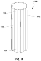
- FIG. 11 depicts an example of a mandrel, generally designated 1100, on which a sheath can be formed, e.g., the sheath depicted in FIG. 9 .
- the mandrel 1100 can include a proximal end 1102 and a distal end 1104.
- the mandrel 1100 can also include an outer periphery 1106.
- the outer periphery 1106 of the mandrel 1100 can be formed with a plurality of longitudinal voids 1108 radially spaced there around.
- a longitudinal fiber can be placed in each longitudinal void 1108.
- a polymeric material can be formed around the mandrel 1100 and cured.
- the longitudinal fibers can be embedded into the material, as described above.
- a method of installing a vascular implant commences at block 1200.
- a vascular implant delivery device can be engaged with a cardio-vascular system of a patient.
- the delivery device can be moved through the cardio-vascular system of the patient.
- decision step 1204 it can be determined whether a target within the cardio-vascular system is reached.
- the location of the vascular implant within the patient can be determined using fluoroscopy and one or more radiopaque bands on the vascular implant, the vascular implant delivery device, or both. If the target is not reached, the method can return to block 1202 and the delivery device can be moved within the cardio-vascular system. Then, the method can continue as described herein.
- a vascular implant can be expelled from the delivery device. Further, at block 1210, lubrication delivery can be ceased. At block 1212, the delivery device can be withdrawn from the patient. Then, the method ends at state 1214.
- a lubrication delivery can commence after step 1202, e.g., if the implant is in contact with an inner diameter of the sheath while being advanced throughout the entire length of the sheath.
- the method can be used to install a vascular implant within a patient.
- the vascular implant can be a stent, a stent graft, an intravenous filter, or some other implant that is delivered to a patient using a cannulated delivery device.
- the vascular implant can be an angioplasty balloon that is temporarily deployed and inflated to treat a patient.
- FIG. 13 through FIG. 19 illustrate examples of implants that can be delivered using the device described herein.
- FIG. 13 and FIG. 14 depict a stent 1300.
- the stent 1300 can be moved through a delivery device in a collapsed configuration, shown in FIG. 13 . After the stent 1300 is deployed, it can move to an expanded configuration, shown in FIG. 14 .
- FIG. 15 and FIG. 16 depict a stent graft 1500.
- the stent 1500 can be moved through a delivery device in a collapsed configuration, shown in FIG. 15 . After the stent graft 1500 is deployed, it can move to an expanded configuration, shown in FIG. 16 .
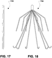
- FIG. 17 and FIG. 18 depict an intravenous filter 1700.
- the filter 1700 can be moved through a delivery device in a collapsed configuration, shown in FIG. 17 . After the filter 1700 is deployed, it can move to an expanded configuration, shown in FIG. 18 .
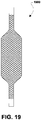
- FIG. 19 illustrates an angioplasty balloon 1900.
- the angioplasty balloon 1900 can be moved through a delivery device in a collapsed configuration, not shown. Moreover, the angioplasty balloon 1900 can be deployed and expanded, as shown in FIG. 19 . After treatment, the angioplasty balloon 1900 can be returned to the collapsed configuration and retracted back into the delivery device.
- embodiments described herein provide one or more sheaths that can be configured to minimize friction between the sheath and an implant to be moved there through.
- the size of the sheath can be minimized, e.g., less than 5 French size, to minimize discomfort to a patient in which the sheath is installed.
- the configuration of an embodiment described herein can also minimize the force required to expel an implant from the sheath.
- embodiments described herein can allow a lubricant to be delivered through the sheath around the implant to further minimize friction and the delivery force.
- embodiments herein can be internally coated with a film or coating having a relatively low coefficient of friction, e.g., less than 0.15.
- a film or coating having a relatively low coefficient of friction e.g., less than 0.15.
- coatings can include diamond film and tungsten disulfide powder.
Landscapes
- Health & Medical Sciences (AREA)
- Engineering & Computer Science (AREA)
- Biomedical Technology (AREA)
- Life Sciences & Earth Sciences (AREA)
- General Health & Medical Sciences (AREA)
- Oral & Maxillofacial Surgery (AREA)
- Heart & Thoracic Surgery (AREA)
- Vascular Medicine (AREA)
- Cardiology (AREA)
- Animal Behavior & Ethology (AREA)
- Transplantation (AREA)
- Public Health (AREA)
- Veterinary Medicine (AREA)
- Physics & Mathematics (AREA)
- Optics & Photonics (AREA)
- Media Introduction/Drainage Providing Device (AREA)
- Prostheses (AREA)
Claims (9)
- Vorrichtung (100) zur Verabreichung eines Gefäßimplantats, umfassend:einen Körper (102);eine Spritzenbefestigung (108), ausgebildet in dem Körper;eine äußere Hülle (500), die sich von dem Körper auserstreckt, wobei die äußere Hülle eine innere Oberfläche (504), ein Lumen (116) und ein distales Ende (114), ausgelegt zur Aufnahme eines Gefäßimplantats (510), umfasst;einen inneren Trägerkatheter (120), gleitfähig angeordnet in der äußeren Hülle, zum Tragen des Gefäßimplantats radial zwischen dem inneren Katheter und der äußeren Hülle;und gekennzeichnet durch:mindestens drei Implantatträgerstrukturen (508), die sich entlang der Länge der äußeren Hülle radial einwärts von dem distalen Ende der äußeren Hülle erstrecken, wobei die Implantatträgerstrukturen zum Stützen und Führen des Gefäßimplantats, das sich durch die äußere Hülle bewegt, ausgelegt sind; und die äußere Hülle weiter mindestens drei längslaufende Leerräume (506) umfasst, die in der inneren Oberfläche der äußeren Hülle ausgebildet sind;wobei jede Implantatstützstruktur zwischen benachbarten längslaufenden Leerräumen ausgebildet ist.
- Vorrichtung nach Anspruch 1, wobei jede Implantatstützstruktur eine längslaufende Faser (906) umfasst, die teilweise in der äußeren Hülle eingebettet ist und wobei jeder Leerraum zwischen benachbarten der längslaufenden Fasern ausgebildet ist.
- Vorrichtung nach Anspruch 2, wobei mindestens fünfzig Prozent (50%) von jeder längslaufenden Faser in der äußeren Hülle eingebettet sind.
- Vorrichtung nach Anspruch 3, wobei nicht mehr als fünfundachtzig Prozent (85%) von jeder längslaufenden Faser in der äußeren Hülle eingebettet sind.
- Vorrichtung nach einem der vorstehenden Ansprüche, wobei die Implantatträgerstrukturen nicht mehr als fünfzig Prozent (50%) einer äußeren Oberfläche des Gefäßimplantats berühren.
- Vorrichtung nach Anspruch 5, wobei die Implantatträgerstrukturen mindestens fünf Prozent (5%) der äußeren Oberfläche des Gefäßimplantats berühren.
- Vorrichtung nach einem der vorstehenden Ansprüche, wobei jeder längslaufende Leerraum ausgelegt ist, um ein Gleitmittel (514) aus der besagten Spritzenbefestigung (108) zu dem Lumen der äußeren Hülle (500) um ein Gefäßimplantat herum abzugeben, wenn das Gefäßimplantat durch die äußere Hülle bewegt wird.
- Implantatverabreichunganordnung nach einem der vorstehenden Ansprüche und enthaltend ein Gefäßimplantat (510), angeordnet in dem distalen Ende der äußeren Hülle.
- Verfahren zur Herstellung einer äußeren Hülle für eine Gefäßimplantatverabreichungsvorrichtung nach Anspruch 1, wobei das Verfahren die Schritte beinhaltet:Einbau einer Vielzahl von Fasern in einem Dorn (1100), der eine äußere Peripherie (1106) aufweist, wobei sich die Fasern entlang einer Länge des Dorns erstrecken und sich radial auswärts über die äußere Peripherie des Dorns hinaus erstrecken; undBilden eines Materials um den Dorn herum im Allgemeinen in einer Röhrenform zur Bildung einer äußeren Hülle, wobei das Material der äußeren Hülle teilweise jede der Vielzahl von Fasern umgibt und Entfernen des Dorns aus dem Inneren der äußeren Hülle.
Applications Claiming Priority (2)
| Application Number | Priority Date | Filing Date | Title |
|---|---|---|---|
| US11/869,938 US8518099B2 (en) | 2007-10-10 | 2007-10-10 | Low friction vascular implant delivery device |
| PCT/US2008/079604 WO2009049224A2 (en) | 2007-10-10 | 2008-10-10 | Low friction vascular implant delivery device |
Publications (3)
| Publication Number | Publication Date |
|---|---|
| EP2178595A2 EP2178595A2 (de) | 2010-04-28 |
| EP2178595A4 EP2178595A4 (de) | 2014-11-19 |
| EP2178595B1 true EP2178595B1 (de) | 2018-04-04 |
Family
ID=40534975
Family Applications (1)
| Application Number | Title | Priority Date | Filing Date |
|---|---|---|---|
| EP08838108.2A Not-in-force EP2178595B1 (de) | 2007-10-10 | 2008-10-10 | Vorrichtung zur verabreichung eines gefässimplantats mit geringer reibung |
Country Status (3)
| Country | Link |
|---|---|
| US (2) | US8518099B2 (de) |
| EP (1) | EP2178595B1 (de) |
| WO (1) | WO2009049224A2 (de) |
Cited By (2)
| Publication number | Priority date | Publication date | Assignee | Title |
|---|---|---|---|---|
| US11690651B2 (en) | 2015-09-04 | 2023-07-04 | The Trustees Of The University Of Pennsylvania | Systems and methods for percutaneous removal of objects from an internal body space |
| US12082845B2 (en) | 2015-09-04 | 2024-09-10 | The Trustees Of The University Of Pennsylvania | Systems and methods for percutaneous removal of objects from an internal body space |
Families Citing this family (21)
| Publication number | Priority date | Publication date | Assignee | Title |
|---|---|---|---|---|
| WO2006124822A1 (en) * | 2005-05-13 | 2006-11-23 | Alveolus, Inc. | Delivery device allowing visual inspection of an intravascular site |
| US8858608B2 (en) * | 2007-12-10 | 2014-10-14 | Cook Medical Technologies Llc | Lubrication apparatus for a delivery and deployment device |
| US20100145429A1 (en) * | 2008-12-09 | 2010-06-10 | Cook Incorporated | Introducer sheath and method of manufacture |
| US20120068132A1 (en) * | 2010-09-17 | 2012-03-22 | W. W. Patterson Company | Manual Marine Winch With Self Releasing Handle |
| WO2012078794A1 (en) | 2010-12-07 | 2012-06-14 | Merit Medical Systems, Inc. | Stent delivery systems and methods |
| US9456912B2 (en) * | 2011-10-31 | 2016-10-04 | Merit Medical Systems, Inc. | Implantable device deployment apparatus |
| WO2015148413A1 (en) | 2014-03-24 | 2015-10-01 | Boston Scientific Scimed, Inc. | Self-expanding stent delivery system |
| EP3265025B1 (de) | 2015-03-05 | 2022-04-13 | Merit Medical Systems, Inc. | Vorrichtung zur freisetzung einer gefässprothese |
| US10470906B2 (en) | 2015-09-15 | 2019-11-12 | Merit Medical Systems, Inc. | Implantable device delivery system |
| EP3377174B1 (de) | 2015-11-20 | 2019-08-28 | Cardiac Pacemakers, Inc. | Abgabesysteme für elektrodenlose herzvorrichtungen |
| AU2016355676B2 (en) | 2015-11-20 | 2018-12-13 | Cardiac Pacemakers, Inc. | Delivery devices and methods for leadless cardiac devices |
| JP7131742B2 (ja) | 2016-09-29 | 2022-09-06 | メリット・メディカル・システムズ・インコーポレイテッド | 血管プロテーゼを受容し、その展開を補助するための柔軟部材 |
| EP3595596B1 (de) | 2017-03-15 | 2023-09-06 | Merit Medical Systems, Inc. | Transluminale freisetzungsvorrichtungen sowie zugehörige kits |
| EP4467111A3 (de) | 2017-03-15 | 2025-03-05 | Merit Medical Systems, Inc. | Transluminale stents |
| USD836194S1 (en) | 2017-03-21 | 2018-12-18 | Merit Medical Systems, Inc. | Stent deployment device |
| US11980394B2 (en) | 2017-06-05 | 2024-05-14 | Bateman Bottle, Llc | Device for removal of implants and associated method of use |
| US10441449B1 (en) * | 2018-05-30 | 2019-10-15 | Vesper Medical, Inc. | Rotary handle stent delivery system and method |
| USD1024310S1 (en) | 2019-03-28 | 2024-04-23 | Bateman Bottle, Llc | Implant removal device |
| US12127939B2 (en) * | 2020-04-30 | 2024-10-29 | Cephea Valve Technologies, Inc. | Catheter lumen lubricant |
| EP4185239A4 (de) | 2020-07-24 | 2024-08-07 | Merit Medical Systems, Inc. | Ösophageale stents und zugehörige verfahren |
| WO2022093710A1 (en) | 2020-10-26 | 2022-05-05 | Merit Medical Systems, Inc. | Esophageal stents with helical thread |
Family Cites Families (14)
| Publication number | Priority date | Publication date | Assignee | Title |
|---|---|---|---|---|
| US5824041A (en) * | 1994-06-08 | 1998-10-20 | Medtronic, Inc. | Apparatus and methods for placement and repositioning of intraluminal prostheses |
| US5755722A (en) * | 1994-12-22 | 1998-05-26 | Boston Scientific Corporation | Stent placement device with medication dispenser and method |
| US5817101A (en) * | 1997-03-13 | 1998-10-06 | Schneider (Usa) Inc | Fluid actuated stent delivery system |
| JP5178984B2 (ja) * | 2000-07-24 | 2013-04-10 | グレイゼル、ジェフリー | 拡張術およびステント術用の補剛バルーン・カテーテル |
| EP1465546B1 (de) * | 2001-11-29 | 2007-07-18 | Cook Incorporated | Zuführsystem für medizinische vorrichtungen |
| US7137993B2 (en) | 2001-12-03 | 2006-11-21 | Xtent, Inc. | Apparatus and methods for delivery of multiple distributed stents |
| US7163553B2 (en) * | 2001-12-28 | 2007-01-16 | Advanced Cardiovascular Systems, Inc. | Intravascular stent and method of use |
| US6849062B2 (en) * | 2002-08-23 | 2005-02-01 | Medtronic Vascular, Inc. | Catheter having a low-friction guidewire lumen and method of manufacture |
| JP2008505713A (ja) * | 2004-07-07 | 2008-02-28 | クック・インコーポレイテッド | グラフト、ステントグラフト、および製造方法 |
| US20060009839A1 (en) * | 2004-07-12 | 2006-01-12 | Scimed Life Systems, Inc. | Composite vascular graft including bioactive agent coating and biodegradable sheath |
| US20060161135A1 (en) * | 2005-01-18 | 2006-07-20 | Vanderwoude Brian J | Ribbed catheter |
| US20060206187A1 (en) * | 2005-03-09 | 2006-09-14 | Cook Incorporated | Stent delivery system |
| US7927362B2 (en) * | 2005-07-21 | 2011-04-19 | Boston Scientific Scimed, Inc. | Laser ablated elastomer sheath profiles to enables stent securement |
| US20090312832A1 (en) * | 2008-06-13 | 2009-12-17 | Cook Incorporated | Slip layer delivery catheter |
-
2007
- 2007-10-10 US US11/869,938 patent/US8518099B2/en active Active
-
2008
- 2008-10-10 EP EP08838108.2A patent/EP2178595B1/de not_active Not-in-force
- 2008-10-10 WO PCT/US2008/079604 patent/WO2009049224A2/en not_active Ceased
-
2013
- 2013-08-23 US US13/975,167 patent/US20130345788A1/en not_active Abandoned
Non-Patent Citations (1)
| Title |
|---|
| None * |
Cited By (2)
| Publication number | Priority date | Publication date | Assignee | Title |
|---|---|---|---|---|
| US11690651B2 (en) | 2015-09-04 | 2023-07-04 | The Trustees Of The University Of Pennsylvania | Systems and methods for percutaneous removal of objects from an internal body space |
| US12082845B2 (en) | 2015-09-04 | 2024-09-10 | The Trustees Of The University Of Pennsylvania | Systems and methods for percutaneous removal of objects from an internal body space |
Also Published As
| Publication number | Publication date |
|---|---|
| US8518099B2 (en) | 2013-08-27 |
| EP2178595A4 (de) | 2014-11-19 |
| US20130345788A1 (en) | 2013-12-26 |
| WO2009049224A3 (en) | 2009-10-22 |
| US20090099636A1 (en) | 2009-04-16 |
| EP2178595A2 (de) | 2010-04-28 |
| WO2009049224A2 (en) | 2009-04-16 |
Similar Documents
| Publication | Publication Date | Title |
|---|---|---|
| US8518099B2 (en) | Low friction vascular implant delivery device | |
| US6859986B2 (en) | Method system for loading a self-expanding stent | |
| US7309349B2 (en) | Friction reducing lubricant for stent loading and stent delivery systems | |
| EP2004253B1 (de) | Stent, intraluminales stentabgagesystem und verfahren zur behandlung einer gefässerkrankung | |
| CA2396724C (en) | Catheter tip designs and method of manufacture | |
| US8506615B2 (en) | Implantable medical endoprosthesis delivery system | |
| US7981148B2 (en) | Stent delivery catheter | |
| US5776142A (en) | Controllable stent delivery system and method | |
| EP2111192B1 (de) | Medizinische systeme und entsprechende verfahren | |
| US7356903B2 (en) | Stent delivery system | |
| AU2019200665A1 (en) | Delivery of medical devices | |
| US20100094392A1 (en) | Expandable Sheath for Introducing an Endovascular Delivery Device into a Body | |
| EP1765445A2 (de) | Katheter | |
| WO1999063909A1 (en) | Stent delivery system | |
| JP2007535365A (ja) | リボン形補綴具の縮小を制御する送達カテーテルおよびその作製および使用の方法 | |
| CA2830668A1 (en) | Endoprosthesis delivery system | |
| JP2008531204A (ja) | 取り外し可能な巻きステント | |
| US20120150271A1 (en) | Buddy wire for the coronary arteries | |
| CN219538586U (zh) | 哑铃状防滑脱微型输尿管狭窄扩张支架 | |
| US20090312830A1 (en) | Balloon arc profile control | |
| US12263319B2 (en) | Reduction in diameter |
Legal Events
| Date | Code | Title | Description |
|---|---|---|---|
| PUAI | Public reference made under article 153(3) epc to a published international application that has entered the european phase |
Free format text: ORIGINAL CODE: 0009012 |
|
| 17P | Request for examination filed |
Effective date: 20100128 |
|
| AK | Designated contracting states |
Kind code of ref document: A2 Designated state(s): AT BE BG CH CY CZ DE DK EE ES FI FR GB GR HR HU IE IS IT LI LT LU LV MC MT NL NO PL PT RO SE SI SK TR |
|
| AX | Request for extension of the european patent |
Extension state: AL BA MK RS |
|
| RIN1 | Information on inventor provided before grant (corrected) |
Inventor name: CHANDUSZKO, ANDRZEJ Inventor name: ABARCA, ENRIQUE |
|
| DAX | Request for extension of the european patent (deleted) | ||
| A4 | Supplementary search report drawn up and despatched |
Effective date: 20141017 |
|
| RIC1 | Information provided on ipc code assigned before grant |
Ipc: A61F 2/962 20130101ALI20141013BHEP Ipc: A61F 2/06 20130101ALI20141013BHEP Ipc: A61M 25/16 20060101AFI20141013BHEP |
|
| GRAP | Despatch of communication of intention to grant a patent |
Free format text: ORIGINAL CODE: EPIDOSNIGR1 |
|
| INTG | Intention to grant announced |
Effective date: 20171206 |
|
| GRAS | Grant fee paid |
Free format text: ORIGINAL CODE: EPIDOSNIGR3 |
|
| GRAA | (expected) grant |
Free format text: ORIGINAL CODE: 0009210 |
|
| AK | Designated contracting states |
Kind code of ref document: B1 Designated state(s): AT BE BG CH CY CZ DE DK EE ES FI FR GB GR HR HU IE IS IT LI LT LU LV MC MT NL NO PL PT RO SE SI SK TR |
|
| REG | Reference to a national code |
Ref country code: GB Ref legal event code: FG4D |
|
| REG | Reference to a national code |
Ref country code: CH Ref legal event code: EP |
|
| REG | Reference to a national code |
Ref country code: AT Ref legal event code: REF Ref document number: 984921 Country of ref document: AT Kind code of ref document: T Effective date: 20180415 |
|
| REG | Reference to a national code |
Ref country code: DE Ref legal event code: R096 Ref document number: 602008054705 Country of ref document: DE |
|
| REG | Reference to a national code |
Ref country code: IE Ref legal event code: FG4D |
|
| REG | Reference to a national code |
Ref country code: NL Ref legal event code: MP Effective date: 20180404 |
|
| REG | Reference to a national code |
Ref country code: LT Ref legal event code: MG4D |
|
| PG25 | Lapsed in a contracting state [announced via postgrant information from national office to epo] |
Ref country code: NL Free format text: LAPSE BECAUSE OF FAILURE TO SUBMIT A TRANSLATION OF THE DESCRIPTION OR TO PAY THE FEE WITHIN THE PRESCRIBED TIME-LIMIT Effective date: 20180404 |
|
| REG | Reference to a national code |
Ref country code: FR Ref legal event code: PLFP Year of fee payment: 11 |
|
| PG25 | Lapsed in a contracting state [announced via postgrant information from national office to epo] |
Ref country code: BG Free format text: LAPSE BECAUSE OF FAILURE TO SUBMIT A TRANSLATION OF THE DESCRIPTION OR TO PAY THE FEE WITHIN THE PRESCRIBED TIME-LIMIT Effective date: 20180704 Ref country code: NO Free format text: LAPSE BECAUSE OF FAILURE TO SUBMIT A TRANSLATION OF THE DESCRIPTION OR TO PAY THE FEE WITHIN THE PRESCRIBED TIME-LIMIT Effective date: 20180704 Ref country code: LT Free format text: LAPSE BECAUSE OF FAILURE TO SUBMIT A TRANSLATION OF THE DESCRIPTION OR TO PAY THE FEE WITHIN THE PRESCRIBED TIME-LIMIT Effective date: 20180404 Ref country code: ES Free format text: LAPSE BECAUSE OF FAILURE TO SUBMIT A TRANSLATION OF THE DESCRIPTION OR TO PAY THE FEE WITHIN THE PRESCRIBED TIME-LIMIT Effective date: 20180404 Ref country code: SE Free format text: LAPSE BECAUSE OF FAILURE TO SUBMIT A TRANSLATION OF THE DESCRIPTION OR TO PAY THE FEE WITHIN THE PRESCRIBED TIME-LIMIT Effective date: 20180404 Ref country code: PL Free format text: LAPSE BECAUSE OF FAILURE TO SUBMIT A TRANSLATION OF THE DESCRIPTION OR TO PAY THE FEE WITHIN THE PRESCRIBED TIME-LIMIT Effective date: 20180404 Ref country code: FI Free format text: LAPSE BECAUSE OF FAILURE TO SUBMIT A TRANSLATION OF THE DESCRIPTION OR TO PAY THE FEE WITHIN THE PRESCRIBED TIME-LIMIT Effective date: 20180404 |
|
| PG25 | Lapsed in a contracting state [announced via postgrant information from national office to epo] |
Ref country code: LV Free format text: LAPSE BECAUSE OF FAILURE TO SUBMIT A TRANSLATION OF THE DESCRIPTION OR TO PAY THE FEE WITHIN THE PRESCRIBED TIME-LIMIT Effective date: 20180404 Ref country code: HR Free format text: LAPSE BECAUSE OF FAILURE TO SUBMIT A TRANSLATION OF THE DESCRIPTION OR TO PAY THE FEE WITHIN THE PRESCRIBED TIME-LIMIT Effective date: 20180404 Ref country code: GR Free format text: LAPSE BECAUSE OF FAILURE TO SUBMIT A TRANSLATION OF THE DESCRIPTION OR TO PAY THE FEE WITHIN THE PRESCRIBED TIME-LIMIT Effective date: 20180705 |
|
| REG | Reference to a national code |
Ref country code: CH Ref legal event code: PK Free format text: BERICHTIGUNGEN |
|
| REG | Reference to a national code |
Ref country code: AT Ref legal event code: MK05 Ref document number: 984921 Country of ref document: AT Kind code of ref document: T Effective date: 20180404 |
|
| PG25 | Lapsed in a contracting state [announced via postgrant information from national office to epo] |
Ref country code: PT Free format text: LAPSE BECAUSE OF FAILURE TO SUBMIT A TRANSLATION OF THE DESCRIPTION OR TO PAY THE FEE WITHIN THE PRESCRIBED TIME-LIMIT Effective date: 20180806 |
|
| RIC2 | Information provided on ipc code assigned after grant |
Ipc: A61F 2/962 20130101ALI20141013BHEP Ipc: A61M 25/16 20060101AFI20141013BHEP Ipc: A61F 2/06 20130101ALI20141013BHEP |
|
| REG | Reference to a national code |
Ref country code: DE Ref legal event code: R097 Ref document number: 602008054705 Country of ref document: DE |
|
| PG25 | Lapsed in a contracting state [announced via postgrant information from national office to epo] |
Ref country code: EE Free format text: LAPSE BECAUSE OF FAILURE TO SUBMIT A TRANSLATION OF THE DESCRIPTION OR TO PAY THE FEE WITHIN THE PRESCRIBED TIME-LIMIT Effective date: 20180404 Ref country code: DK Free format text: LAPSE BECAUSE OF FAILURE TO SUBMIT A TRANSLATION OF THE DESCRIPTION OR TO PAY THE FEE WITHIN THE PRESCRIBED TIME-LIMIT Effective date: 20180404 Ref country code: SK Free format text: LAPSE BECAUSE OF FAILURE TO SUBMIT A TRANSLATION OF THE DESCRIPTION OR TO PAY THE FEE WITHIN THE PRESCRIBED TIME-LIMIT Effective date: 20180404 Ref country code: CZ Free format text: LAPSE BECAUSE OF FAILURE TO SUBMIT A TRANSLATION OF THE DESCRIPTION OR TO PAY THE FEE WITHIN THE PRESCRIBED TIME-LIMIT Effective date: 20180404 Ref country code: RO Free format text: LAPSE BECAUSE OF FAILURE TO SUBMIT A TRANSLATION OF THE DESCRIPTION OR TO PAY THE FEE WITHIN THE PRESCRIBED TIME-LIMIT Effective date: 20180404 Ref country code: AT Free format text: LAPSE BECAUSE OF FAILURE TO SUBMIT A TRANSLATION OF THE DESCRIPTION OR TO PAY THE FEE WITHIN THE PRESCRIBED TIME-LIMIT Effective date: 20180404 |
|
| REG | Reference to a national code |
Ref country code: CH Ref legal event code: PK Free format text: BERICHTIGUNGEN |
|
| PLBE | No opposition filed within time limit |
Free format text: ORIGINAL CODE: 0009261 |
|
| STAA | Information on the status of an ep patent application or granted ep patent |
Free format text: STATUS: NO OPPOSITION FILED WITHIN TIME LIMIT |
|
| RIC2 | Information provided on ipc code assigned after grant |
Ipc: A61F 2/06 20130101ALI20141013BHEP Ipc: A61M 25/16 20060101AFI20141013BHEP Ipc: A61F 2/962 20130101ALI20141013BHEP |
|
| PG25 | Lapsed in a contracting state [announced via postgrant information from national office to epo] |
Ref country code: IT Free format text: LAPSE BECAUSE OF FAILURE TO SUBMIT A TRANSLATION OF THE DESCRIPTION OR TO PAY THE FEE WITHIN THE PRESCRIBED TIME-LIMIT Effective date: 20180404 |
|
| 26N | No opposition filed |
Effective date: 20190107 |
|
| PG25 | Lapsed in a contracting state [announced via postgrant information from national office to epo] |
Ref country code: SI Free format text: LAPSE BECAUSE OF FAILURE TO SUBMIT A TRANSLATION OF THE DESCRIPTION OR TO PAY THE FEE WITHIN THE PRESCRIBED TIME-LIMIT Effective date: 20180404 |
|
| REG | Reference to a national code |
Ref country code: CH Ref legal event code: PL |
|
| REG | Reference to a national code |
Ref country code: BE Ref legal event code: MM Effective date: 20181031 |
|
| PG25 | Lapsed in a contracting state [announced via postgrant information from national office to epo] |
Ref country code: MC Free format text: LAPSE BECAUSE OF FAILURE TO SUBMIT A TRANSLATION OF THE DESCRIPTION OR TO PAY THE FEE WITHIN THE PRESCRIBED TIME-LIMIT Effective date: 20180404 Ref country code: LU Free format text: LAPSE BECAUSE OF NON-PAYMENT OF DUE FEES Effective date: 20181010 |
|
| REG | Reference to a national code |
Ref country code: IE Ref legal event code: MM4A |
|
| PG25 | Lapsed in a contracting state [announced via postgrant information from national office to epo] |
Ref country code: CH Free format text: LAPSE BECAUSE OF NON-PAYMENT OF DUE FEES Effective date: 20181031 Ref country code: LI Free format text: LAPSE BECAUSE OF NON-PAYMENT OF DUE FEES Effective date: 20181031 Ref country code: BE Free format text: LAPSE BECAUSE OF NON-PAYMENT OF DUE FEES Effective date: 20181031 |
|
| PG25 | Lapsed in a contracting state [announced via postgrant information from national office to epo] |
Ref country code: IE Free format text: LAPSE BECAUSE OF NON-PAYMENT OF DUE FEES Effective date: 20181010 |
|
| PG25 | Lapsed in a contracting state [announced via postgrant information from national office to epo] |
Ref country code: MT Free format text: LAPSE BECAUSE OF NON-PAYMENT OF DUE FEES Effective date: 20181010 |
|
| PG25 | Lapsed in a contracting state [announced via postgrant information from national office to epo] |
Ref country code: TR Free format text: LAPSE BECAUSE OF FAILURE TO SUBMIT A TRANSLATION OF THE DESCRIPTION OR TO PAY THE FEE WITHIN THE PRESCRIBED TIME-LIMIT Effective date: 20180404 |
|
| PG25 | Lapsed in a contracting state [announced via postgrant information from national office to epo] |
Ref country code: HU Free format text: LAPSE BECAUSE OF FAILURE TO SUBMIT A TRANSLATION OF THE DESCRIPTION OR TO PAY THE FEE WITHIN THE PRESCRIBED TIME-LIMIT; INVALID AB INITIO Effective date: 20081010 Ref country code: CY Free format text: LAPSE BECAUSE OF FAILURE TO SUBMIT A TRANSLATION OF THE DESCRIPTION OR TO PAY THE FEE WITHIN THE PRESCRIBED TIME-LIMIT Effective date: 20180404 |
|
| PG25 | Lapsed in a contracting state [announced via postgrant information from national office to epo] |
Ref country code: IS Free format text: LAPSE BECAUSE OF FAILURE TO SUBMIT A TRANSLATION OF THE DESCRIPTION OR TO PAY THE FEE WITHIN THE PRESCRIBED TIME-LIMIT Effective date: 20180804 |
|
| PGFP | Annual fee paid to national office [announced via postgrant information from national office to epo] |
Ref country code: GB Payment date: 20220922 Year of fee payment: 15 |
|
| PGFP | Annual fee paid to national office [announced via postgrant information from national office to epo] |
Ref country code: FR Payment date: 20220922 Year of fee payment: 15 |
|
| PGFP | Annual fee paid to national office [announced via postgrant information from national office to epo] |
Ref country code: DE Payment date: 20220616 Year of fee payment: 15 |
|
| REG | Reference to a national code |
Ref country code: DE Ref legal event code: R119 Ref document number: 602008054705 Country of ref document: DE |
|
| GBPC | Gb: european patent ceased through non-payment of renewal fee |
Effective date: 20231010 |
|
| PG25 | Lapsed in a contracting state [announced via postgrant information from national office to epo] |
Ref country code: GB Free format text: LAPSE BECAUSE OF NON-PAYMENT OF DUE FEES Effective date: 20231010 |
|
| PG25 | Lapsed in a contracting state [announced via postgrant information from national office to epo] |
Ref country code: GB Free format text: LAPSE BECAUSE OF NON-PAYMENT OF DUE FEES Effective date: 20231010 Ref country code: FR Free format text: LAPSE BECAUSE OF NON-PAYMENT OF DUE FEES Effective date: 20231031 Ref country code: DE Free format text: LAPSE BECAUSE OF NON-PAYMENT OF DUE FEES Effective date: 20240501 |