EP2004253B1 - Stent, intraluminales stentabgagesystem und verfahren zur behandlung einer gefässerkrankung - Google Patents
Stent, intraluminales stentabgagesystem und verfahren zur behandlung einer gefässerkrankung Download PDFInfo
- Publication number
- EP2004253B1 EP2004253B1 EP07710486A EP07710486A EP2004253B1 EP 2004253 B1 EP2004253 B1 EP 2004253B1 EP 07710486 A EP07710486 A EP 07710486A EP 07710486 A EP07710486 A EP 07710486A EP 2004253 B1 EP2004253 B1 EP 2004253B1
- Authority
- EP
- European Patent Office
- Prior art keywords
- stent
- biodegradable
- elongate member
- polymer
- catheter
- Prior art date
- Legal status (The legal status is an assumption and is not a legal conclusion. Google has not performed a legal analysis and makes no representation as to the accuracy of the status listed.)
- Not-in-force
Links
- 238000000034 method Methods 0.000 title abstract description 13
- 230000002792 vascular Effects 0.000 title abstract description 8
- 229920000642 polymer Polymers 0.000 claims abstract description 36
- 230000003014 reinforcing effect Effects 0.000 claims abstract description 18
- 239000003814 drug Substances 0.000 claims description 27
- 229940124597 therapeutic agent Drugs 0.000 claims description 21
- FYYHWMGAXLPEAU-UHFFFAOYSA-N Magnesium Chemical compound [Mg] FYYHWMGAXLPEAU-UHFFFAOYSA-N 0.000 claims description 2
- 229910052749 magnesium Inorganic materials 0.000 claims description 2
- 239000011777 magnesium Substances 0.000 claims description 2
- 239000000835 fiber Substances 0.000 claims 3
- 230000000379 polymerizing effect Effects 0.000 claims 1
- 229920001730 Moisture cure polyurethane Polymers 0.000 abstract description 15
- 239000000463 material Substances 0.000 description 11
- -1 polypropylene Polymers 0.000 description 9
- 239000013307 optical fiber Substances 0.000 description 8
- 208000037803 restenosis Diseases 0.000 description 7
- 229940079593 drug Drugs 0.000 description 6
- 238000002399 angioplasty Methods 0.000 description 5
- 239000003795 chemical substances by application Substances 0.000 description 5
- 229920005989 resin Polymers 0.000 description 5
- 239000011347 resin Substances 0.000 description 5
- WYURNTSHIVDZCO-UHFFFAOYSA-N Tetrahydrofuran Chemical compound C1CCOC1 WYURNTSHIVDZCO-UHFFFAOYSA-N 0.000 description 4
- 210000001367 artery Anatomy 0.000 description 4
- 210000004204 blood vessel Anatomy 0.000 description 4
- 239000011248 coating agent Substances 0.000 description 4
- 238000000576 coating method Methods 0.000 description 4
- 238000010828 elution Methods 0.000 description 4
- 239000007788 liquid Substances 0.000 description 4
- 239000000203 mixture Substances 0.000 description 4
- CSCPPACGZOOCGX-UHFFFAOYSA-N Acetone Chemical compound CC(C)=O CSCPPACGZOOCGX-UHFFFAOYSA-N 0.000 description 3
- YMWUJEATGCHHMB-UHFFFAOYSA-N Dichloromethane Chemical compound ClCCl YMWUJEATGCHHMB-UHFFFAOYSA-N 0.000 description 3
- XEKOWRVHYACXOJ-UHFFFAOYSA-N Ethyl acetate Chemical compound CCOC(C)=O XEKOWRVHYACXOJ-UHFFFAOYSA-N 0.000 description 3
- 239000004677 Nylon Substances 0.000 description 3
- 239000003102 growth factor Substances 0.000 description 3
- 229920001778 nylon Polymers 0.000 description 3
- IAKHMKGGTNLKSZ-INIZCTEOSA-N (S)-colchicine Chemical compound C1([C@@H](NC(C)=O)CC2)=CC(=O)C(OC)=CC=C1C1=C2C=C(OC)C(OC)=C1OC IAKHMKGGTNLKSZ-INIZCTEOSA-N 0.000 description 2
- HEDRZPFGACZZDS-UHFFFAOYSA-N Chloroform Chemical compound ClC(Cl)Cl HEDRZPFGACZZDS-UHFFFAOYSA-N 0.000 description 2
- 239000004812 Fluorinated ethylene propylene Substances 0.000 description 2
- SECXISVLQFMRJM-UHFFFAOYSA-N N-Methylpyrrolidone Chemical compound CN1CCCC1=O SECXISVLQFMRJM-UHFFFAOYSA-N 0.000 description 2
- 150000001875 compounds Chemical class 0.000 description 2
- 239000000470 constituent Substances 0.000 description 2
- 229920001577 copolymer Polymers 0.000 description 2
- 210000004351 coronary vessel Anatomy 0.000 description 2
- 239000012530 fluid Substances 0.000 description 2
- 239000000017 hydrogel Substances 0.000 description 2
- 230000028709 inflammatory response Effects 0.000 description 2
- 239000003550 marker Substances 0.000 description 2
- 229920009441 perflouroethylene propylene Polymers 0.000 description 2
- BASFCYQUMIYNBI-UHFFFAOYSA-N platinum Chemical compound [Pt] BASFCYQUMIYNBI-UHFFFAOYSA-N 0.000 description 2
- 229920000139 polyethylene terephthalate Polymers 0.000 description 2
- 239000005020 polyethylene terephthalate Substances 0.000 description 2
- 238000006116 polymerization reaction Methods 0.000 description 2
- 229920001343 polytetrafluoroethylene Polymers 0.000 description 2
- 239000004810 polytetrafluoroethylene Substances 0.000 description 2
- 239000012858 resilient material Substances 0.000 description 2
- 239000000243 solution Substances 0.000 description 2
- 239000002904 solvent Substances 0.000 description 2
- 239000000126 substance Substances 0.000 description 2
- YLQBMQCUIZJEEH-UHFFFAOYSA-N tetrahydrofuran Natural products C=1C=COC=1 YLQBMQCUIZJEEH-UHFFFAOYSA-N 0.000 description 2
- 230000001225 therapeutic effect Effects 0.000 description 2
- 238000012800 visualization Methods 0.000 description 2
- PUDHBTGHUJUUFI-SCTWWAJVSA-N (4r,7s,10s,13r,16s,19r)-10-(4-aminobutyl)-n-[(2s,3r)-1-amino-3-hydroxy-1-oxobutan-2-yl]-19-[[(2r)-2-amino-3-naphthalen-2-ylpropanoyl]amino]-16-[(4-hydroxyphenyl)methyl]-13-(1h-indol-3-ylmethyl)-6,9,12,15,18-pentaoxo-7-propan-2-yl-1,2-dithia-5,8,11,14,17-p Chemical compound C([C@H]1C(=O)N[C@H](CC=2C3=CC=CC=C3NC=2)C(=O)N[C@@H](CCCCN)C(=O)N[C@H](C(N[C@@H](CSSC[C@@H](C(=O)N1)NC(=O)[C@H](N)CC=1C=C2C=CC=CC2=CC=1)C(=O)N[C@@H]([C@@H](C)O)C(N)=O)=O)C(C)C)C1=CC=C(O)C=C1 PUDHBTGHUJUUFI-SCTWWAJVSA-N 0.000 description 1
- DSUFPYCILZXJFF-UHFFFAOYSA-N 4-[[4-[[4-(pentoxycarbonylamino)cyclohexyl]methyl]cyclohexyl]carbamoyloxy]butyl n-[4-[[4-(butoxycarbonylamino)cyclohexyl]methyl]cyclohexyl]carbamate Chemical compound C1CC(NC(=O)OCCCCC)CCC1CC1CCC(NC(=O)OCCCCOC(=O)NC2CCC(CC3CCC(CC3)NC(=O)OCCCC)CC2)CC1 DSUFPYCILZXJFF-UHFFFAOYSA-N 0.000 description 1
- 108020000948 Antisense Oligonucleotides Proteins 0.000 description 1
- 206010003210 Arteriosclerosis Diseases 0.000 description 1
- 208000037260 Atherosclerotic Plaque Diseases 0.000 description 1
- 239000005528 B01AC05 - Ticlopidine Substances 0.000 description 1
- 229940127291 Calcium channel antagonist Drugs 0.000 description 1
- 102000008186 Collagen Human genes 0.000 description 1
- 108010035532 Collagen Proteins 0.000 description 1
- 229920001780 ECTFE Polymers 0.000 description 1
- 108090000790 Enzymes Proteins 0.000 description 1
- 102000004190 Enzymes Human genes 0.000 description 1
- 239000004593 Epoxy Substances 0.000 description 1
- 108010056764 Eptifibatide Proteins 0.000 description 1
- JOYRKODLDBILNP-UHFFFAOYSA-N Ethyl urethane Chemical compound CCOC(N)=O JOYRKODLDBILNP-UHFFFAOYSA-N 0.000 description 1
- AEMRFAOFKBGASW-UHFFFAOYSA-N Glycolic acid Polymers OCC(O)=O AEMRFAOFKBGASW-UHFFFAOYSA-N 0.000 description 1
- HTTJABKRGRZYRN-UHFFFAOYSA-N Heparin Chemical compound OC1C(NC(=O)C)C(O)OC(COS(O)(=O)=O)C1OC1C(OS(O)(=O)=O)C(O)C(OC2C(C(OS(O)(=O)=O)C(OC3C(C(O)C(O)C(O3)C(O)=O)OS(O)(=O)=O)C(CO)O2)NS(O)(=O)=O)C(C(O)=O)O1 HTTJABKRGRZYRN-UHFFFAOYSA-N 0.000 description 1
- 102000007625 Hirudins Human genes 0.000 description 1
- 108010007267 Hirudins Proteins 0.000 description 1
- 101000599951 Homo sapiens Insulin-like growth factor I Proteins 0.000 description 1
- 206010020772 Hypertension Diseases 0.000 description 1
- 206010061218 Inflammation Diseases 0.000 description 1
- 102100037852 Insulin-like growth factor I Human genes 0.000 description 1
- 102000005755 Intercellular Signaling Peptides and Proteins Human genes 0.000 description 1
- 108010070716 Intercellular Signaling Peptides and Proteins Proteins 0.000 description 1
- FBOZXECLQNJBKD-ZDUSSCGKSA-N L-methotrexate Chemical compound C=1N=C2N=C(N)N=C(N)C2=NC=1CN(C)C1=CC=C(C(=O)N[C@@H](CCC(O)=O)C(O)=O)C=C1 FBOZXECLQNJBKD-ZDUSSCGKSA-N 0.000 description 1
- PCZOHLXUXFIOCF-UHFFFAOYSA-N Monacolin X Natural products C12C(OC(=O)C(C)CC)CC(C)C=C2C=CC(C)C1CCC1CC(O)CC(=O)O1 PCZOHLXUXFIOCF-UHFFFAOYSA-N 0.000 description 1
- 101001055320 Myxine glutinosa Insulin-like growth factor Proteins 0.000 description 1
- 229930012538 Paclitaxel Natural products 0.000 description 1
- 229920002732 Polyanhydride Polymers 0.000 description 1
- 229920002614 Polyether block amide Polymers 0.000 description 1
- 239000004698 Polyethylene Substances 0.000 description 1
- 229920000954 Polyglycolide Polymers 0.000 description 1
- 229920000331 Polyhydroxybutyrate Polymers 0.000 description 1
- 229920001710 Polyorthoester Polymers 0.000 description 1
- 239000004743 Polypropylene Substances 0.000 description 1
- 108010023197 Streptokinase Proteins 0.000 description 1
- 208000007536 Thrombosis Diseases 0.000 description 1
- 108090000373 Tissue Plasminogen Activator Proteins 0.000 description 1
- 102000003978 Tissue Plasminogen Activator Human genes 0.000 description 1
- 102000004887 Transforming Growth Factor beta Human genes 0.000 description 1
- 108090001012 Transforming Growth Factor beta Proteins 0.000 description 1
- GSNOZLZNQMLSKJ-UHFFFAOYSA-N Trapidil Chemical compound CCN(CC)C1=CC(C)=NC2=NC=NN12 GSNOZLZNQMLSKJ-UHFFFAOYSA-N 0.000 description 1
- 108090000435 Urokinase-type plasminogen activator Proteins 0.000 description 1
- 102000003990 Urokinase-type plasminogen activator Human genes 0.000 description 1
- 108010019530 Vascular Endothelial Growth Factors Proteins 0.000 description 1
- 102000005789 Vascular Endothelial Growth Factors Human genes 0.000 description 1
- 206010047139 Vasoconstriction Diseases 0.000 description 1
- 229920006099 Vestamid® Polymers 0.000 description 1
- 241000700605 Viruses Species 0.000 description 1
- 229960000446 abciximab Drugs 0.000 description 1
- 239000002253 acid Substances 0.000 description 1
- NIXOWILDQLNWCW-UHFFFAOYSA-N acrylic acid group Chemical group C(C=C)(=O)O NIXOWILDQLNWCW-UHFFFAOYSA-N 0.000 description 1
- 239000004037 angiogenesis inhibitor Substances 0.000 description 1
- 230000001621 anti-mitogenic effect Effects 0.000 description 1
- 230000001028 anti-proliverative effect Effects 0.000 description 1
- 239000003963 antioxidant agent Substances 0.000 description 1
- 229940127218 antiplatelet drug Drugs 0.000 description 1
- 239000000074 antisense oligonucleotide Substances 0.000 description 1
- 238000012230 antisense oligonucleotides Methods 0.000 description 1
- 210000000013 bile duct Anatomy 0.000 description 1
- 229920002988 biodegradable polymer Polymers 0.000 description 1
- 239000004621 biodegradable polymer Substances 0.000 description 1
- 230000015572 biosynthetic process Effects 0.000 description 1
- 230000017531 blood circulation Effects 0.000 description 1
- 230000008933 bodily movement Effects 0.000 description 1
- 239000000480 calcium channel blocker Substances 0.000 description 1
- UUAGAQFQZIEFAH-UHFFFAOYSA-N chlorotrifluoroethylene Chemical group FC(F)=C(F)Cl UUAGAQFQZIEFAH-UHFFFAOYSA-N 0.000 description 1
- 229960001338 colchicine Drugs 0.000 description 1
- 229920001436 collagen Polymers 0.000 description 1
- 238000007598 dipping method Methods 0.000 description 1
- 239000013013 elastic material Substances 0.000 description 1
- 229940088598 enzyme Drugs 0.000 description 1
- SEACYXSIPDVVMV-UHFFFAOYSA-L eosin Y Chemical compound [Na+].[Na+].[O-]C(=O)C1=CC=CC=C1C1=C2C=C(Br)C(=O)C(Br)=C2OC2=C(Br)C([O-])=C(Br)C=C21 SEACYXSIPDVVMV-UHFFFAOYSA-L 0.000 description 1
- 229960004468 eptifibatide Drugs 0.000 description 1
- GLGOPUHVAZCPRB-LROMGURASA-N eptifibatide Chemical compound N1C(=O)[C@H](CC(O)=O)NC(=O)CNC(=O)[C@H](CCCCNC(=N)N)NC(=O)CCSSC[C@@H](C(N)=O)NC(=O)[C@@H]2CCCN2C(=O)[C@@H]1CC1=CN=C2[C]1C=CC=C2 GLGOPUHVAZCPRB-LROMGURASA-N 0.000 description 1
- 210000003238 esophagus Anatomy 0.000 description 1
- HQQADJVZYDDRJT-UHFFFAOYSA-N ethene;prop-1-ene Chemical group C=C.CC=C HQQADJVZYDDRJT-UHFFFAOYSA-N 0.000 description 1
- 239000003527 fibrinolytic agent Substances 0.000 description 1
- 238000002594 fluoroscopy Methods 0.000 description 1
- 210000001035 gastrointestinal tract Anatomy 0.000 description 1
- 239000000499 gel Substances 0.000 description 1
- PCHJSUWPFVWCPO-UHFFFAOYSA-N gold Chemical compound [Au] PCHJSUWPFVWCPO-UHFFFAOYSA-N 0.000 description 1
- 239000010931 gold Substances 0.000 description 1
- 229910052737 gold Inorganic materials 0.000 description 1
- 229960002897 heparin Drugs 0.000 description 1
- 229920000669 heparin Polymers 0.000 description 1
- WQPDUTSPKFMPDP-OUMQNGNKSA-N hirudin Chemical compound C([C@@H](C(=O)N[C@@H](CCC(O)=O)C(=O)N[C@@H](CCC(O)=O)C(=O)N[C@@H]([C@@H](C)CC)C(=O)N1[C@@H](CCC1)C(=O)N[C@@H](CCC(O)=O)C(=O)N[C@@H](CCC(O)=O)C(=O)N[C@@H](CC=1C=CC(OS(O)(=O)=O)=CC=1)C(=O)N[C@@H](CC(C)C)C(=O)N[C@@H](CCC(N)=O)C(O)=O)NC(=O)[C@H](CC(O)=O)NC(=O)CNC(=O)[C@H](CC(O)=O)NC(=O)[C@H](CC(N)=O)NC(=O)[C@H](CC=1NC=NC=1)NC(=O)[C@H](CO)NC(=O)[C@H](CCC(N)=O)NC(=O)[C@H]1N(CCC1)C(=O)[C@H](CCCCN)NC(=O)[C@H]1N(CCC1)C(=O)[C@@H](NC(=O)CNC(=O)[C@H](CCC(O)=O)NC(=O)CNC(=O)[C@@H](NC(=O)[C@@H](NC(=O)[C@H]1NC(=O)[C@H](CCC(N)=O)NC(=O)[C@H](CC(N)=O)NC(=O)[C@H](CCCCN)NC(=O)[C@H](CCC(O)=O)NC(=O)CNC(=O)[C@H](CC(O)=O)NC(=O)[C@H](CO)NC(=O)CNC(=O)[C@H](CC(C)C)NC(=O)[C@H]([C@@H](C)CC)NC(=O)[C@@H]2CSSC[C@@H](C(=O)N[C@@H](CCC(O)=O)C(=O)NCC(=O)N[C@@H](CO)C(=O)N[C@@H](CC(N)=O)C(=O)N[C@H](C(=O)N[C@H](C(NCC(=O)N[C@@H](CCC(N)=O)C(=O)NCC(=O)N[C@@H](CC(N)=O)C(=O)N[C@@H](CCCCN)C(=O)N2)=O)CSSC1)C(C)C)NC(=O)[C@H](CC(C)C)NC(=O)[C@H]1NC(=O)[C@H](CC(C)C)NC(=O)[C@H](CC(N)=O)NC(=O)[C@H](CCC(N)=O)NC(=O)CNC(=O)[C@H](CO)NC(=O)[C@H](CCC(O)=O)NC(=O)[C@H]([C@@H](C)O)NC(=O)[C@@H](NC(=O)[C@H](CC(O)=O)NC(=O)[C@@H](NC(=O)[C@H](CC=2C=CC(O)=CC=2)NC(=O)[C@@H](NC(=O)[C@@H](N)C(C)C)C(C)C)[C@@H](C)O)CSSC1)C(C)C)[C@@H](C)O)[C@@H](C)O)C1=CC=CC=C1 WQPDUTSPKFMPDP-OUMQNGNKSA-N 0.000 description 1
- 229940006607 hirudin Drugs 0.000 description 1
- 230000007062 hydrolysis Effects 0.000 description 1
- 238000006460 hydrolysis reaction Methods 0.000 description 1
- 229920001477 hydrophilic polymer Polymers 0.000 description 1
- 206010020718 hyperplasia Diseases 0.000 description 1
- 238000001727 in vivo Methods 0.000 description 1
- 238000011065 in-situ storage Methods 0.000 description 1
- 230000004054 inflammatory process Effects 0.000 description 1
- 239000003112 inhibitor Substances 0.000 description 1
- 238000002347 injection Methods 0.000 description 1
- 239000007924 injection Substances 0.000 description 1
- 208000014674 injury Diseases 0.000 description 1
- 238000002608 intravascular ultrasound Methods 0.000 description 1
- 230000000302 ischemic effect Effects 0.000 description 1
- 108010021336 lanreotide Proteins 0.000 description 1
- 229960002437 lanreotide Drugs 0.000 description 1
- PCZOHLXUXFIOCF-BXMDZJJMSA-N lovastatin Chemical compound C([C@H]1[C@@H](C)C=CC2=C[C@H](C)C[C@@H]([C@H]12)OC(=O)[C@@H](C)CC)C[C@@H]1C[C@@H](O)CC(=O)O1 PCZOHLXUXFIOCF-BXMDZJJMSA-N 0.000 description 1
- 229960004844 lovastatin Drugs 0.000 description 1
- QLJODMDSTUBWDW-UHFFFAOYSA-N lovastatin hydroxy acid Natural products C1=CC(C)C(CCC(O)CC(O)CC(O)=O)C2C(OC(=O)C(C)CC)CC(C)C=C21 QLJODMDSTUBWDW-UHFFFAOYSA-N 0.000 description 1
- 239000011159 matrix material Substances 0.000 description 1
- 230000001404 mediated effect Effects 0.000 description 1
- 229910052751 metal Inorganic materials 0.000 description 1
- 239000002184 metal Substances 0.000 description 1
- 229910001092 metal group alloy Inorganic materials 0.000 description 1
- 229960000485 methotrexate Drugs 0.000 description 1
- 150000002823 nitrates Chemical class 0.000 description 1
- 239000002840 nitric oxide donor Substances 0.000 description 1
- 229960001592 paclitaxel Drugs 0.000 description 1
- 229920003023 plastic Polymers 0.000 description 1
- 239000004033 plastic Substances 0.000 description 1
- 239000000106 platelet aggregation inhibitor Substances 0.000 description 1
- 229910052697 platinum Inorganic materials 0.000 description 1
- 239000005015 poly(hydroxybutyrate) Substances 0.000 description 1
- 229920000218 poly(hydroxyvalerate) Polymers 0.000 description 1
- 229920000747 poly(lactic acid) Polymers 0.000 description 1
- 229920002627 poly(phosphazenes) Polymers 0.000 description 1
- 229920001610 polycaprolactone Polymers 0.000 description 1
- 239000004632 polycaprolactone Substances 0.000 description 1
- 229920000573 polyethylene Polymers 0.000 description 1
- 239000004626 polylactic acid Substances 0.000 description 1
- 239000002861 polymer material Substances 0.000 description 1
- 229920001155 polypropylene Polymers 0.000 description 1
- 238000004393 prognosis Methods 0.000 description 1
- 108090000623 proteins and genes Proteins 0.000 description 1
- ZAHRKKWIAAJSAO-UHFFFAOYSA-N rapamycin Natural products COCC(O)C(=C/C(C)C(=O)CC(OC(=O)C1CCCCN1C(=O)C(=O)C2(O)OC(CC(OC)C(=CC=CC=CC(C)CC(C)C(=O)C)C)CCC2C)C(C)CC3CCC(O)C(C3)OC)C ZAHRKKWIAAJSAO-UHFFFAOYSA-N 0.000 description 1
- 230000002787 reinforcement Effects 0.000 description 1
- 238000005096 rolling process Methods 0.000 description 1
- 229920000431 shape-memory polymer Polymers 0.000 description 1
- 229960002930 sirolimus Drugs 0.000 description 1
- QFJCIRLUMZQUOT-HPLJOQBZSA-N sirolimus Chemical compound C1C[C@@H](O)[C@H](OC)C[C@@H]1C[C@@H](C)[C@H]1OC(=O)[C@@H]2CCCCN2C(=O)C(=O)[C@](O)(O2)[C@H](C)CC[C@H]2C[C@H](OC)/C(C)=C/C=C/C=C/[C@@H](C)C[C@@H](C)C(=O)[C@H](OC)[C@H](O)/C(C)=C/[C@@H](C)C(=O)C1 QFJCIRLUMZQUOT-HPLJOQBZSA-N 0.000 description 1
- 238000005507 spraying Methods 0.000 description 1
- 229960005202 streptokinase Drugs 0.000 description 1
- RCINICONZNJXQF-MZXODVADSA-N taxol Chemical compound O([C@@H]1[C@@]2(C[C@@H](C(C)=C(C2(C)C)[C@H](C([C@]2(C)[C@@H](O)C[C@H]3OC[C@]3([C@H]21)OC(C)=O)=O)OC(=O)C)OC(=O)[C@H](O)[C@@H](NC(=O)C=1C=CC=CC=1)C=1C=CC=CC=1)O)C(=O)C1=CC=CC=C1 RCINICONZNJXQF-MZXODVADSA-N 0.000 description 1
- ZRKFYGHZFMAOKI-QMGMOQQFSA-N tgfbeta Chemical compound C([C@H](NC(=O)[C@H](C(C)C)NC(=O)CNC(=O)[C@H](CCC(O)=O)NC(=O)[C@H](CCCNC(N)=N)NC(=O)[C@H](CC(N)=O)NC(=O)[C@H](CC(C)C)NC(=O)[C@H]([C@@H](C)O)NC(=O)[C@H](CCC(O)=O)NC(=O)[C@H]([C@@H](C)O)NC(=O)[C@H](CC(C)C)NC(=O)CNC(=O)[C@H](C)NC(=O)[C@H](CO)NC(=O)[C@H](CCC(N)=O)NC(=O)[C@@H](NC(=O)[C@H](C)NC(=O)[C@H](C)NC(=O)[C@@H](NC(=O)[C@H](CC(C)C)NC(=O)[C@@H](N)CCSC)C(C)C)[C@@H](C)CC)C(=O)N[C@@H]([C@@H](C)O)C(=O)N[C@@H](C(C)C)C(=O)N[C@@H](CC=1C=CC=CC=1)C(=O)N[C@@H](C)C(=O)N1[C@@H](CCC1)C(=O)N[C@@H]([C@@H](C)O)C(=O)N[C@@H](CC(N)=O)C(=O)N[C@@H](CCC(O)=O)C(=O)N[C@@H](C)C(=O)N[C@@H](CC=1C=CC=CC=1)C(=O)N[C@@H](CCCNC(N)=N)C(=O)N[C@@H](C)C(=O)N[C@@H](CC(C)C)C(=O)N1[C@@H](CCC1)C(=O)N1[C@@H](CCC1)C(=O)N[C@@H](CCCNC(N)=N)C(=O)N[C@@H](CCC(O)=O)C(=O)N[C@@H](CCCNC(N)=N)C(=O)N[C@@H](CO)C(=O)N[C@@H](CCCNC(N)=N)C(=O)N[C@@H](CC(C)C)C(=O)N[C@@H](CC(C)C)C(O)=O)C1=CC=C(O)C=C1 ZRKFYGHZFMAOKI-QMGMOQQFSA-N 0.000 description 1
- 229920002725 thermoplastic elastomer Polymers 0.000 description 1
- 239000012815 thermoplastic material Substances 0.000 description 1
- PHWBOXQYWZNQIN-UHFFFAOYSA-N ticlopidine Chemical compound ClC1=CC=CC=C1CN1CC(C=CS2)=C2CC1 PHWBOXQYWZNQIN-UHFFFAOYSA-N 0.000 description 1
- 229960005001 ticlopidine Drugs 0.000 description 1
- 229960000187 tissue plasminogen activator Drugs 0.000 description 1
- 229960000363 trapidil Drugs 0.000 description 1
- 230000008733 trauma Effects 0.000 description 1
- YFHICDDUDORKJB-UHFFFAOYSA-N trimethylene carbonate Chemical compound O=C1OCCCO1 YFHICDDUDORKJB-UHFFFAOYSA-N 0.000 description 1
- WFKWXMTUELFFGS-UHFFFAOYSA-N tungsten Chemical compound [W] WFKWXMTUELFFGS-UHFFFAOYSA-N 0.000 description 1
- 239000010937 tungsten Substances 0.000 description 1
- 229910052721 tungsten Inorganic materials 0.000 description 1
- 229960005356 urokinase Drugs 0.000 description 1
- 210000005166 vasculature Anatomy 0.000 description 1
- 230000025033 vasoconstriction Effects 0.000 description 1
- 229940124549 vasodilator Drugs 0.000 description 1
- 239000003071 vasodilator agent Substances 0.000 description 1
- CGTADGCBEXYWNE-JUKNQOCSSA-N zotarolimus Chemical compound N1([C@H]2CC[C@@H](C[C@@H](C)[C@H]3OC(=O)[C@@H]4CCCCN4C(=O)C(=O)[C@@]4(O)[C@H](C)CC[C@H](O4)C[C@@H](/C(C)=C/C=C/C=C/[C@@H](C)C[C@@H](C)C(=O)[C@H](OC)[C@H](O)/C(C)=C/[C@@H](C)C(=O)C3)OC)C[C@H]2OC)C=NN=N1 CGTADGCBEXYWNE-JUKNQOCSSA-N 0.000 description 1
- 229950009819 zotarolimus Drugs 0.000 description 1
Images


Classifications
-
- A—HUMAN NECESSITIES
- A61—MEDICAL OR VETERINARY SCIENCE; HYGIENE
- A61L—METHODS OR APPARATUS FOR STERILISING MATERIALS OR OBJECTS IN GENERAL; DISINFECTION, STERILISATION OR DEODORISATION OF AIR; CHEMICAL ASPECTS OF BANDAGES, DRESSINGS, ABSORBENT PADS OR SURGICAL ARTICLES; MATERIALS FOR BANDAGES, DRESSINGS, ABSORBENT PADS OR SURGICAL ARTICLES
- A61L31/00—Materials for other surgical articles, e.g. stents, stent-grafts, shunts, surgical drapes, guide wires, materials for adhesion prevention, occluding devices, surgical gloves, tissue fixation devices
- A61L31/14—Materials characterised by their function or physical properties, e.g. injectable or lubricating compositions, shape-memory materials, surface modified materials
- A61L31/148—Materials at least partially resorbable by the body
-
- A—HUMAN NECESSITIES
- A61—MEDICAL OR VETERINARY SCIENCE; HYGIENE
- A61L—METHODS OR APPARATUS FOR STERILISING MATERIALS OR OBJECTS IN GENERAL; DISINFECTION, STERILISATION OR DEODORISATION OF AIR; CHEMICAL ASPECTS OF BANDAGES, DRESSINGS, ABSORBENT PADS OR SURGICAL ARTICLES; MATERIALS FOR BANDAGES, DRESSINGS, ABSORBENT PADS OR SURGICAL ARTICLES
- A61L31/00—Materials for other surgical articles, e.g. stents, stent-grafts, shunts, surgical drapes, guide wires, materials for adhesion prevention, occluding devices, surgical gloves, tissue fixation devices
- A61L31/14—Materials characterised by their function or physical properties, e.g. injectable or lubricating compositions, shape-memory materials, surface modified materials
- A61L31/16—Biologically active materials, e.g. therapeutic substances
-
- A—HUMAN NECESSITIES
- A61—MEDICAL OR VETERINARY SCIENCE; HYGIENE
- A61L—METHODS OR APPARATUS FOR STERILISING MATERIALS OR OBJECTS IN GENERAL; DISINFECTION, STERILISATION OR DEODORISATION OF AIR; CHEMICAL ASPECTS OF BANDAGES, DRESSINGS, ABSORBENT PADS OR SURGICAL ARTICLES; MATERIALS FOR BANDAGES, DRESSINGS, ABSORBENT PADS OR SURGICAL ARTICLES
- A61L2300/00—Biologically active materials used in bandages, wound dressings, absorbent pads or medical devices
Definitions
- the present invention relates generally to stents. More particularly, the invention relates to a stent, an intraluminal stent delivery system, and a method of treating a vascular condition.
- Balloon angioplasty has been used for the treatment of narrowed and occluded blood vessels.
- a frequent complication associated with the procedure is restenosis, or vessel re-narrowing.
- restenosis can occur in about half of patients.
- implantable prosthetic devices such as stents, have been used to reduce the rate of angioplasty related restenosis by about half. The use of such prosthetic devices has greatly improved the prognosis of these patients.
- the objective in angioplasty is to enlarge the lumen of the affected coronary artery by radial hydraulic expansion. This is generally accomplished by inflating a balloon within the narrowed lumen of the affected artery. Radial expansion of the coronary artery may occur in several different dimensions, and is related to the nature of the plaque. Soft, fatty plaque deposits are flattened by the balloon, while hardened deposits are cracked and split to enlarge the lumen. The wall of the artery itself may also be stretched as the balloon is inflated. With simple angioplasty, the balloon may be threaded through the artery with a catheter and inflated at the place where the blood vessel is blocked. After the procedure, the balloon is then removed. The stent may then be used to support open the artery. The stent may be deployed along with the balloon or after the balloon is removed.
- the stent may be formed from a generally tubular body that can be expanded from a collapsed state into a deployed state.
- the stent body may include a plurality of elongated element lengths (e.g., wire lengths, or the like) that are connected together to permit the stent body to be expanded.
- the stent may be coupled to a deployment system (e.g., a catheter) in a collapsed state.
- a deployment system e.g., a catheter
- the stent may be compressed within a lumen formed within a catheter or onto a catheter balloon.
- the catheter including the stent may be then advanced endovascularly (or within another vessel type) to the afflicted region of the body passage. While fed through the vessel, the stent remains in the collapsed state.
- the stent may be expanded radially outward into the deployed state.
- the stent may be expanded into its deployed state by inflating the catheter balloon so that expansion of the stent is achieved simultaneously with the inflation of the balloon.
- the stent may be manufactured from a resilient material such that when it is collapsed, the stent may naturally expand from a "tense” collapsed state into a "relaxed” deployed state. In such a case, the stent self-expands as it is removed from the catheter lumen.
- the radial strength of the stent should be sufficient to withstand restenosis in order to maintain vascular patency.
- Certain stents e.g., non-metallic, bioabsorbable types
- lack sufficient radial strength under stressful conditions e.g., high blood pressure, bodily movements, etc.
- stressful conditions e.g., high blood pressure, bodily movements, etc.
- a reduced collapsed stent profile size contributes to a reduced size in the deployment system.
- numerous benefits may be provided by a reduction in stent and (potentially) deployment system size.
- a reduction in stent and (potentially) deployment system size For example, as the stent is advanced to the site of deployment, it may encounter a sometimes tortuous and narrow network of vessels. Smaller sized stents and deployment systems may facilitate easier negotiation of such vessel networks.
- Other benefits of reducing the size of the deployment system may include less disruption of an atheroma and plaque that could lead to emboli, less disruption of blood flow, less likelihood of vessel wall damage, and reduced vessel puncture size for intraluminal access. Accordingly, it would be desirable to minimize the stent collapsed profile size.
- EP 103 57 747 describes a biodegradable stent including a shape-memory polymer material .
- EP 0 617 930 describes an expandable endovascular stent having a double-walled sleeve filled with a photocurable material.
- FIG. 1 illustrates an intraluminal stent delivery system in accordance with the present invention
- FIG. 2 illustrates a stent in accordance with the present invention
- FIG. 2A illustrates a cross section of a portion of the stent illustrated in FIG. 2 ;
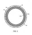
- FIG. 3 illustrates a cross-section of the stent of FIG. 2 shown deployed in a vessel, in accordance with the present invention.
- FIG. 4 illustrates a flowchart of a method of treating a vascular condition, in accordance with one embodiment of the present invention.
- FIG. 1 is a perspective view of an intraluminal stent delivery system in accordance with one embodiment of the present invention and shown generally by numeral 10.
- System 10 includes a catheter 20, a balloon 30 operably attached to the catheter 20, and a stent 40 disposed on the balloon 30.
- Stent 40 (shown in a compressed configuration) remains compressed on the balloon 30 during advancement through the vasculature.
- the compressed stent 40 includes a small profile (i.e., cross-sectional size).
- a sheath 41 may be disposed on the stent 40 to protect the stent 40 as well as the vessel walls during advancement.
- intravascular and/or implantable prosthetic devices in accordance with the present invention may be deployed in other vessels, such as a bile duct, intestinal tract, esophagus, and airway.
- biodegradable refers to substances that degrade (e.g., via hydrolysis) to at least a certain extent within the body. Biodegradable substances are biocompatible and preferably incur a reduced inflammatory response.
- a "radial" direction is one that is perpendicular to the axis of a vessel.
- catheter 20 includes an elongated tubular member manufactured from one or more polymeric materials.
- catheter 20 includes a metallic reinforcement element.
- the catheter is constructed from very flexible materials to facilitate advancement into intricate access locations. Numerous over-the-wire, rapid-exchange, and other catheter designs are known and may be adapted for use with the present invention.
- Catheter 20 can be secured at its proximal end to a suitable Luer fitting 22, and may include a distal rounded end 24 to reduce harmful contact with a vessel.
- Catheter 20 can be manufactured from a material such as a thermoplastic elastomer, urethane, polymer, polypropylene, plastic, ethelene chlorotrifluoroethylene (ECTFE), polytetrafluoroethylene (PTFE), fluorinated ethylene propylene copolymer (FEP), nylon, Pebax® resin, Vestamid® nylon, Tecoflex® resin, Halar® resin, Hyflon® resin, Pellathane® resin, combinations thereof, and the like.
- Catheter 20 includes an aperture formed at the distal rounded end 24 allowing advancement over a guidewire 26.
- Balloon 30 may be any variety of balloons or other devices capable of expanding the stent 40 (e.g., by providing outward radial forces). Balloon 30 may be manufactured from any sufficiently elastic material such as polyethylene, polyethylene terephthalate (PET), nylon, or the like. Those skilled in the art will recognize that the stent 40 may be expanded using a variety of means and that the present invention is not limited to balloon expansion.
- PET polyethylene terephthalate
- an optical fiber 28 is positioned adjacent the balloon 30 and the distal rounded end 24.
- the main body of the optical fiber 28 is substantially straight and extends through an inflation lumen of the balloon 30 and along the length of catheter 20, terminating proximally at a connecter arm at the Luer fitting 22.
- Optical fiber 28 is operably connected to a light source 32 via its proximal portion 36.
- the distal portion 34 of the optical fiber 28 adjacent the stent 40 is abraded, as shown by hash marks 29, to diffuse light from the optical fiber 28 in multiple directions.
- the optical fiber 28 is attached outside the catheter or, alternatively, freestanding or as part of another medical device.
- the optical fiber 28 may be any material or apparatus capable of emitting light and may be connected to a light source by any means of conveying light to the stent.
- a light source running under its own power source e.g., a battery
- the stent 40 is a generally tubular structure including a passageway that extends along a longitudinal axis A. Stent 40 can be configured for various lengths when in the deployed configuration. In one embodiment, the length of stent 40 is predetermined based on the dimensions of the treatment site.
- Stent 40 includes a flexible biodegradable elongate member 42, which is shaped in a coiled configuration.
- elongate member 42 comprises an elongate member wall 48 forming a cavity 54.
- elongate member 42 has a generally oval cross section.
- elongate member 42 may have a generally circular cross section.
- Elongate member 42 can be manufactured from numerous biodegradable materials such as a thermoplastic material of poly-lactic acid (PLA), polyglycolyic acid (PGA), and/or collagen, which demonstrate high biocompatibility with reduced inflammatory response.
- PLA poly-lactic acid
- PGA polyglycolyic acid
- collagen collagen
- a biodegradable reinforcing member 50 is positioned adjacent the elongate member 42. Reinforcing member 50 provides an outward radial force for supporting the stent 40 in the deployed configuration.
- reinforcing member 50 is a biodegradable magnesium wire positioned along an inner surface 56 of the elongate member 42.
- the reinforcing member 50 can be positioned outside or integrated into the elongate member wall 48.
- the reinforcing member 50 is manufactured from a resilient material for providing radial force (i.e., to resist restenosis). Reinforcing member 50 is positioned along the length of the elongate member 42 in the coiled configuration.
- the end portions of the reinforcing member 50 can be shaped to reduce sharp edges. In one embodiment, the end portions form hoops or rings 52. Those skilled in the art will recognize that the size, geometry, number, and constituent material of the reinforcing member 50 may vary from the description and illustrations provided herein. For example, in another embodiment, the reinforcing member may be struts, wires, mesh, and the like, for supporting the stent 40.
- Cavity 54 of the elongate member 42 is at least partially filled with a biodegradable, photo-curable polymer 60.
- the end portions 44, 46 of the elongate member 42 are sealed to retain the photo-curable polymer 60.
- the end portions 44, 46 may be sealed by any means known in the art such as, for example, thermal sealed, bonded, clipped, and the like, to retain the photo-curable polymer 60.
- the polymer 60 is in a fluid pre-polymer form, such as a liquid, gel, and the like.
- the pre-polymer comprises a cross-linked hydrophilic polymer, commonly known as hydrogels.
- the polymer 60 also includes a photoinitiator, such as eosin Y, which accelerates polymerization of the pre-polymer to the polymer 60.
- a photoinitiator such as eosin Y
- numerous compounds may be added to the polymer 60 to alter its curative properties.
- the pre-polymer liquid contained within cavity 54 is flexible.
- mounting of the stent 40 on the balloon 30 is performed with a mechanical wrapping device or other similar device for wrapping the stent in a helical fashion. Mounting the stent 40 tightly around the balloon 30 provides a reduced collapsed profile size.
- the liquid pre-polymer polymerizes or "cures" in vivo into the polymer 60.
- the polymerization of the liquid pre-polymer solidifies the pre-polymer to form the cured polymer 60.
- the cured polymer 60 along with the reinforcing member 50, supports the elongate member 42 at the treatment site.
- the cured polymer 60 and the reinforcing member 50 supports the elongate member 42 in the radial direction to counteract vasoconstriction.
- the degree of the radial strength and support provided by the cured polymer depends on the nature of the cured polymer 60. For example, an epoxy or acrylic polymeric material may provide greater radial strength than a hydrogel.
- the stent 40 includes at least one therapeutic agent.
- the therapeutic agent is integrated with the polymer 60 thereby allowing elution as the elongate member 42 degrades. It should be noted that any polymer(s) incorporated in a therapeutic agent may or may not be the same as the biodegradable, photo-curable polymer 60.
- the therapeutic agent comprises one or more drugs, polymers, a component thereof, a combination thereof, and the like.
- the therapeutic agent can include a mixture of a drug and a polymer as known in the art.
- Some exemplary drug classes that may be included are antiangiogenesis agents, antiendothelin agents, antimitogenic factors, antioxidants, antiplatelet agents, antiproliferative agents, antisense oligonucleotides, antithrombogenic agents, calcium channel blockers, clot dissolving enzymes, growth factors, growth factor inhibitors, nitrates, nitric oxide releasing agents, vasodilators, virus-mediated gene transfer agents, agents having a desirable therapeutic application, and the like.
- drugs include abciximab, angiopeptin, colchicine, eptifibatide, heparin, hirudin, lovastatin, methotrexate, rapamycin, streptokinase, taxol, ticlopidine, tissue plasminogen activator, trapidil, urokinase, zotarolimus, and growth factors VEGF, TGF-beta, IGF, PDGF, and FGF.
- the therapeutic agent polymer provides a matrix for incorporating the drug within a coating, or may provide means for slowing the elution of an underlying therapeutic agent when it comprises a cap coat or is incorporated into the photo-curable polymer. It should be noted that the polymer(s) of the therapeutic agent is not necessarily the same compound as the photo-curable polymer 60.
- biodegradable polymers that may be adapted for use with the present invention include, but are not limited to, polycaprolactone, polylactide, polyglycolide, polyorthoesters, polyanhydrides, poly(amides), poly(alkyl-2-cyanocrylates), poly(dihydropyrans), poly(acetals), poly(phosphazenes), poly(dioxinones), trimethylene carbonate, polyhydroxybutyrate, polyhydroxyvalerate, their copolymers, blends, and copolymers blends, combinations thereof, and the like.
- Solvents are used to dissolve the therapeutic agent and polymer to comprise a therapeutic agent coating solution.
- Some exemplary solvents that may be adapted for use with the present invention include, but are not limited to, acetone, ethyl acetate, tetrahydrofuran (THF), chloroform, N-methylpyrrolidone (NMP), methylene chloride, and the like.
- a therapeutic agent solution comprising the coating may be applied to the stent 40 by any of numerous strategies known in the art including, but not limited to, spraying, dipping, rolling, nozzle injection, and the like. Numerous strategies of applying the coating in accordance with the present invention are known in the art.
- the therapeutic agent may be incorporated within the photocurable polymer 60.
- two or more therapeutic agents are incorporated into the stent and are released having a multiple elution profile.
- a first therapeutic agent disposed on the elongate member 42 is released to reduce inflammation.
- the first agent may be released on a short-term basis to overcome surgical trauma of the treatment.
- the second therapeutic agent is disposed in the photo-curable polymer 60 for reducing endovascular restenosis. As the elongate member 42 biodegrades, the second therapeutic agent is released on a longer-term basis.
- FIG. 3 illustrates the stent 40 in cross-section deployed within a vessel 70, taken along line B-B of FIG. 2 .
- An outer portion of the elongate member 42a contacts an inner wall of the vessel 70.
- Outer portion 42a of the elongate member 42 is supported by the reinforcing member 50, polymer 60, and inner portion 42b of the elongate member 42, thereby providing axial strength to the stent 40.
- FIG. 4 illustrates a flowchart of a method 400 of treating a vascular condition, in accordance with one embodiment of the present invention.
- the present description relates to the treatment of a vascular condition, which in this case is an ischemic blood vessel including a vulnerable plaque.
- the method begins at step 410.
- the stent 40 is delivered to a treatment site with the catheter 20.
- catheter 20 is advanced to treatment site over a pre-positioned guidewire 26.
- at least one radiopaque marker may be disposed on the stent 40, catheter 20, and or component thereof to allow in situ visualization and proper advancement, positioning, and deployment of the stent 40.
- the market(s) may be manufactured from a number of materials used for visualization in the art including radiopaque materials such as, for example, platinum, gold, tungsten, metal, metal alloy, and the like. Marker(s) may be visualized by fluoroscopy, IVUS, and other methods known in the art. Those skilled in the art will recognize that numerous devices and methodologies may be utilized for positioning an intraluminal stent in accordance with the present invention.
- the balloon 30 and stent 60 are expanded radially into contact with the vessel wall.
- Balloon 30 is expanded by addition of fluid within its lumen.
- a sheath 41, covering stent 40 during delivery to the treatment site is retracted prior to expanding balloon 30.
- the pre-polymer positioned within the stent is polymerized.
- light is passed distally from the light source 32 via the optical fiber 28 toward the deployed stent 40. As previously described, the light is diffused adjacent the stent 40 to provide light exposure to the pre-polymer. Light is administered until the pre-polymer has nearly or fully polymerized or cured.
- the intensity, wavelength, and duration of light exposure can depend on factors such as, for example, the size of the elongate member 42 and amount of pre-polymer.
- factors such as, for example, the size of the elongate member 42 and amount of pre-polymer.
- the strategy for diffusing and delivering the light energy to the pre-polymer may vary from the description and illustrations provided herein.
- different pre-polymers and stent geometries may require alternative light sources from those described herein.
- the deployed stent is supported in a radial direction.
- the polymerized polymer 60 serves to set the stent 40 in the deployed position and provide radial support.
- the biodegradable reinforcing member 50 provides additional support to the deployed stent 40.
- At step 460 at least one therapeutic agent is eluted from the stent.
- a single therapeutic agent is in the stent 40, polymer 60.
- two or more therapeutic agents are released with a multiple elution profile.
- Method 400 ends at step 470.
Landscapes
- Health & Medical Sciences (AREA)
- Life Sciences & Earth Sciences (AREA)
- General Health & Medical Sciences (AREA)
- Epidemiology (AREA)
- Veterinary Medicine (AREA)
- Public Health (AREA)
- Animal Behavior & Ethology (AREA)
- Heart & Thoracic Surgery (AREA)
- Surgery (AREA)
- Vascular Medicine (AREA)
- Molecular Biology (AREA)
- Engineering & Computer Science (AREA)
- Chemical & Material Sciences (AREA)
- Medicinal Chemistry (AREA)
- Biomedical Technology (AREA)
- Media Introduction/Drainage Providing Device (AREA)
- Materials For Medical Uses (AREA)
Claims (11)
- Biologisch abbaubarer Stent (40), umfassend:ein biologisch abbaubares, flexibles, längliches Element (42), das eine längliche Elementwand (48) enthält, die einen Hohlraum (54) umgibt, wobei das biologisch abbaubare, längliche Element (42) eine spiralförmige Konfiguration umfasst und mindestens ein Endabschnitt (44, 46) des länglichen Elements (42) versiegelt ist;ein biologisch abbaubares Verstärkungselement (50), das innerhalb oder neben der länglichen Elementwand (48) positioniert ist, um das biologisch abbaubare längliche Element (42) zu stützen; undein biologisch abbaubares, lichthärtbares Polymer (60), das innerhalb des Hohlraumes (54) des länglichen Elements (42) positioniert ist;wobei der Stent (40)des Weiteren mindestens ein therapeutisches Mittel umfasst, das mit dem Polymer (60) integriert ist.
- Stent nach Anspruch 1, wobei das biologisch abbaubare, lichthärtbare Polymer (60) eine Stütze für den Stent (40) in radialer Richtung bereitstellt, wenn er sich in der entfalteten Konfiguration befindet.
- Stent nach Anspruch 1, wobei das mindestens eine therapeutische Mittel mit einem im Voraus bestimmten Profil eluiert wird.
- Stent nach Anspruch 1, wobei das Verstärkungselement (50) einen Magnesiumdraht umfasst.
- Stent nach Anspruch 1, des Weiteren umfassend einen Photoinitiator, der innerhalb des Hohlraumes (54) positioniert ist.
- Abgabesystem für einen intraluminalen Stent (10), umfassend:einen Katheter (20);ein aufblähbares Element (30), das betriebsbereit an dem Katheter (20) befestigt ist; undeinen biologisch abbaubaren Stent (40) nach einem der vorangehenden Ansprüche.
- System nach Anspruch 6, wobei das Verstärkungselement (50) ein spiralförmiges Element umfasst.
- System nach Anspruch 6, wobei das biologisch abbaubare, lichthärtbare Polymer (60) eine axiale Stütze für den Stent (40) bereitstellt.
- System nach Anspruch 6, des Weiteren umfassend mindestens ein faseroptisches Element (28), das neben dem länglichen Element (42) positioniert ist, wobei das faseroptische Element (28) betriebsbereit an einer Lichtquelle (32) befestigt ist, um zum Polymerisieren des lichthärtbaren Polymers (60) zu dienen.
- System nach Anspruch 9, wobei das mindestens eine faseroptische Element (28) ein Lichtstreuungselement (34) zum radialen Streuen von Licht umfasst.
- System nach Anspruch 6, des Weiteren umfassend einen Photoinitiator, der innerhalb des länglichen Elements (42) positioniert ist.
Applications Claiming Priority (2)
| Application Number | Priority Date | Filing Date | Title |
|---|---|---|---|
| US11/277,419 US20070225799A1 (en) | 2006-03-24 | 2006-03-24 | Stent, intraluminal stent delivery system, and method of treating a vascular condition |
| PCT/US2007/062226 WO2007112159A2 (en) | 2006-03-24 | 2007-02-15 | Stent, intraluminal stent delivery system, and method of treating a vascular condition |
Publications (2)
| Publication Number | Publication Date |
|---|---|
| EP2004253A2 EP2004253A2 (de) | 2008-12-24 |
| EP2004253B1 true EP2004253B1 (de) | 2011-01-05 |
Family
ID=38352979
Family Applications (1)
| Application Number | Title | Priority Date | Filing Date |
|---|---|---|---|
| EP07710486A Not-in-force EP2004253B1 (de) | 2006-03-24 | 2007-02-15 | Stent, intraluminales stentabgagesystem und verfahren zur behandlung einer gefässerkrankung |
Country Status (5)
| Country | Link |
|---|---|
| US (1) | US20070225799A1 (de) |
| EP (1) | EP2004253B1 (de) |
| AT (1) | ATE494019T1 (de) |
| DE (1) | DE602007011740D1 (de) |
| WO (1) | WO2007112159A2 (de) |
Families Citing this family (39)
| Publication number | Priority date | Publication date | Assignee | Title |
|---|---|---|---|---|
| AU2002345328A1 (en) | 2001-06-27 | 2003-03-03 | Remon Medical Technologies Ltd. | Method and device for electrochemical formation of therapeutic species in vivo |
| US8840660B2 (en) | 2006-01-05 | 2014-09-23 | Boston Scientific Scimed, Inc. | Bioerodible endoprostheses and methods of making the same |
| US8089029B2 (en) | 2006-02-01 | 2012-01-03 | Boston Scientific Scimed, Inc. | Bioabsorbable metal medical device and method of manufacture |
| US8048150B2 (en) | 2006-04-12 | 2011-11-01 | Boston Scientific Scimed, Inc. | Endoprosthesis having a fiber meshwork disposed thereon |
| EP2040771A2 (de) * | 2006-05-16 | 2009-04-01 | Medtronic Vascular, Inc. | Bioresorbierbare magnesium-verstärkte polymerstents |
| JP2009545407A (ja) | 2006-08-02 | 2009-12-24 | ボストン サイエンティフィック サイムド,インコーポレイテッド | 三次元分解制御を備えたエンドプロテーゼ |
| EP2959925B1 (de) | 2006-09-15 | 2018-08-29 | Boston Scientific Limited | Medizinische vorrichtungen und verfahren zu ihrer herstellung |
| ATE490794T1 (de) | 2006-09-15 | 2010-12-15 | Boston Scient Scimed Inc | Biologisch erodierbare endoprothese mit biostabilen anorganischen schichten |
| WO2008034066A1 (en) | 2006-09-15 | 2008-03-20 | Boston Scientific Limited | Bioerodible endoprostheses and methods of making the same |
| JP2010503489A (ja) | 2006-09-15 | 2010-02-04 | ボストン サイエンティフィック リミテッド | 生体内分解性内部人工器官およびその製造方法 |
| CA2663762A1 (en) | 2006-09-18 | 2008-03-27 | Boston Scientific Limited | Endoprostheses |
| US8414526B2 (en) | 2006-11-20 | 2013-04-09 | Lutonix, Inc. | Medical device rapid drug releasing coatings comprising oils, fatty acids, and/or lipids |
| US8430055B2 (en) | 2008-08-29 | 2013-04-30 | Lutonix, Inc. | Methods and apparatuses for coating balloon catheters |
| US8414525B2 (en) | 2006-11-20 | 2013-04-09 | Lutonix, Inc. | Drug releasing coatings for medical devices |
| US9700704B2 (en) | 2006-11-20 | 2017-07-11 | Lutonix, Inc. | Drug releasing coatings for balloon catheters |
| US8998846B2 (en) | 2006-11-20 | 2015-04-07 | Lutonix, Inc. | Drug releasing coatings for balloon catheters |
| US8425459B2 (en) | 2006-11-20 | 2013-04-23 | Lutonix, Inc. | Medical device rapid drug releasing coatings comprising a therapeutic agent and a contrast agent |
| US8414909B2 (en) | 2006-11-20 | 2013-04-09 | Lutonix, Inc. | Drug releasing coatings for medical devices |
| US9737640B2 (en) | 2006-11-20 | 2017-08-22 | Lutonix, Inc. | Drug releasing coatings for medical devices |
| US8414910B2 (en) | 2006-11-20 | 2013-04-09 | Lutonix, Inc. | Drug releasing coatings for medical devices |
| US20080276935A1 (en) | 2006-11-20 | 2008-11-13 | Lixiao Wang | Treatment of asthma and chronic obstructive pulmonary disease with anti-proliferate and anti-inflammatory drugs |
| ES2506144T3 (es) | 2006-12-28 | 2014-10-13 | Boston Scientific Limited | Endoprótesis bioerosionables y procedimiento de fabricación de las mismas |
| JP2009000276A (ja) * | 2007-06-21 | 2009-01-08 | Olympus Medical Systems Corp | 医療用チューブ、医療用器具、ステントセット及び内視鏡装置 |
| US8052745B2 (en) | 2007-09-13 | 2011-11-08 | Boston Scientific Scimed, Inc. | Endoprosthesis |
| US7998192B2 (en) | 2008-05-09 | 2011-08-16 | Boston Scientific Scimed, Inc. | Endoprostheses |
| US8236046B2 (en) | 2008-06-10 | 2012-08-07 | Boston Scientific Scimed, Inc. | Bioerodible endoprosthesis |
| US7985252B2 (en) | 2008-07-30 | 2011-07-26 | Boston Scientific Scimed, Inc. | Bioerodible endoprosthesis |
| US8382824B2 (en) | 2008-10-03 | 2013-02-26 | Boston Scientific Scimed, Inc. | Medical implant having NANO-crystal grains with barrier layers of metal nitrides or fluorides |
| EP2403546A2 (de) | 2009-03-02 | 2012-01-11 | Boston Scientific Scimed, Inc. | Selbstpufferende medizinische implantate |
| US8435281B2 (en) | 2009-04-10 | 2013-05-07 | Boston Scientific Scimed, Inc. | Bioerodible, implantable medical devices incorporating supersaturated magnesium alloys |
| WO2011119573A1 (en) | 2010-03-23 | 2011-09-29 | Boston Scientific Scimed, Inc. | Surface treated bioerodible metal endoprostheses |
| US20130053946A1 (en) * | 2011-08-30 | 2013-02-28 | Boston Scientific Scimed, Inc. | Bioabsorbable polymer stent with metal stiffeners |
| US20170258611A1 (en) * | 2014-05-09 | 2017-09-14 | Mayo Foundation For Medical Education And Research | Devices and methods for forming stents in vivo |
| CN106572914B (zh) * | 2014-06-27 | 2020-09-11 | 波士顿科学国际有限公司 | 用来将含有支架的医疗装置附接至组织的组合物、装置、套件和方法 |
| US10707531B1 (en) | 2016-09-27 | 2020-07-07 | New Dominion Enterprises Inc. | All-inorganic solvents for electrolytes |
| CN110623779B (zh) * | 2018-06-21 | 2023-07-25 | 连新龙 | 一种介入用防护套 |
| US12414819B2 (en) | 2020-11-03 | 2025-09-16 | The University Of British Columbia | Hydrogel co-injection and real-time opto-electromagnetic modification device for tunable in-vivo delivery |
| CN115486976A (zh) * | 2021-11-24 | 2022-12-20 | 上海百心安生物技术股份有限公司 | 一种血管支架系统 |
| CN115737197A (zh) * | 2022-11-23 | 2023-03-07 | 深圳先进技术研究院 | 腔道支架 |
Family Cites Families (45)
| Publication number | Priority date | Publication date | Assignee | Title |
|---|---|---|---|---|
| US6171338B1 (en) * | 1988-11-10 | 2001-01-09 | Biocon, Oy | Biodegradable surgical implants and devices |
| FR2660867B1 (fr) * | 1990-04-13 | 1998-07-10 | Georges Boussignac | Catheter a endoprothese. |
| DE4104702C2 (de) * | 1991-02-15 | 1996-01-18 | Malte Neuss | Implantate für Organwege in Wendelform |
| NL9101159A (nl) * | 1991-07-03 | 1993-02-01 | Industrial Res Bv | Vormvast te maken uitzetbare ring, cylinder of huls. |
| US5500013A (en) * | 1991-10-04 | 1996-03-19 | Scimed Life Systems, Inc. | Biodegradable drug delivery vascular stent |
| US5599352A (en) * | 1992-03-19 | 1997-02-04 | Medtronic, Inc. | Method of making a drug eluting stent |
| US5334201A (en) * | 1993-03-12 | 1994-08-02 | Cowan Kevin P | Permanent stent made of a cross linkable material |
| NL9300500A (nl) * | 1993-03-22 | 1994-10-17 | Industrial Res Bv | Uitzetbare, holle huls voor het plaatselijk ondersteunen en/of versterken van een lichaamsvat, alsmede werkwijze voor het vervaardigen daarvan. |
| US5716410A (en) * | 1993-04-30 | 1998-02-10 | Scimed Life Systems, Inc. | Temporary stent and method of use |
| WO1995010989A1 (en) * | 1993-10-19 | 1995-04-27 | Scimed Life Systems, Inc. | Intravascular stent pump |
| US5665063A (en) * | 1994-06-24 | 1997-09-09 | Focal, Inc. | Methods for application of intraluminal photopolymerized gels |
| US5593403A (en) * | 1994-09-14 | 1997-01-14 | Scimed Life Systems Inc. | Method for modifying a stent in an implanted site |
| NL9500493A (nl) * | 1995-03-13 | 1996-10-01 | Cordis Europ | Catheter met lichtgeleider. |
| US5591199A (en) * | 1995-06-07 | 1997-01-07 | Porter; Christopher H. | Curable fiber composite stent and delivery system |
| US5676685A (en) * | 1995-06-22 | 1997-10-14 | Razavi; Ali | Temporary stent |
| US5779673A (en) * | 1995-06-26 | 1998-07-14 | Focal, Inc. | Devices and methods for application of intraluminal photopolymerized gels |
| JP2000510006A (ja) * | 1996-04-29 | 2000-08-08 | ダブリュ.エル.ゴア アンド アソシエイツ,インコーポレイティド | 静脈弁の能力回復装置 |
| NL1003178C2 (nl) * | 1996-05-21 | 1997-11-25 | Cordis Europ | Buisvormige prothese van uithardbaar materiaal. |
| ZA9710342B (en) * | 1996-11-25 | 1998-06-10 | Alza Corp | Directional drug delivery stent and method of use. |
| US6039757A (en) * | 1997-03-12 | 2000-03-21 | Cardiosynopsis, Inc. | In situ formed fenestrated stent |
| US6241691B1 (en) * | 1997-12-05 | 2001-06-05 | Micrus Corporation | Coated superelastic stent |
| US6063111A (en) * | 1998-03-31 | 2000-05-16 | Cordis Corporation | Stent aneurysm treatment system and method |
| US6358276B1 (en) * | 1998-09-30 | 2002-03-19 | Impra, Inc. | Fluid containing endoluminal stent |
| US7018401B1 (en) * | 1999-02-01 | 2006-03-28 | Board Of Regents, The University Of Texas System | Woven intravascular devices and methods for making the same and apparatus for delivery of the same |
| US6364904B1 (en) * | 1999-07-02 | 2002-04-02 | Scimed Life Systems, Inc. | Helically formed stent/graft assembly |
| US6652570B2 (en) * | 1999-07-02 | 2003-11-25 | Scimed Life Systems, Inc. | Composite vascular graft |
| US20020077693A1 (en) * | 2000-12-19 | 2002-06-20 | Barclay Bruce J. | Covered, coiled drug delivery stent and method |
| US6974473B2 (en) * | 2000-06-30 | 2005-12-13 | Vascular Architects, Inc. | Function-enhanced thrombolytic AV fistula and method |
| US6503538B1 (en) * | 2000-08-30 | 2003-01-07 | Cornell Research Foundation, Inc. | Elastomeric functional biodegradable copolyester amides and copolyester urethanes |
| US6569129B1 (en) * | 2000-09-13 | 2003-05-27 | Mayo Foundation For Medical Education And Research | Biological revascularization |
| US6485512B1 (en) * | 2000-09-27 | 2002-11-26 | Advanced Cardiovascular Systems, Inc. | Two-stage light curable stent and delivery system |
| MXPA03009727A (es) * | 2001-04-26 | 2004-01-29 | Control Delivery Sys Inc | SISTEMA DE SUMINISTRO DE FaRMACOS DE LIBERACIoN PROLONGADA QUE CONTIENE COFARMACOS. |
| US6585755B2 (en) * | 2001-06-29 | 2003-07-01 | Advanced Cardiovascular | Polymeric stent suitable for imaging by MRI and fluoroscopy |
| AUPR847201A0 (en) * | 2001-10-26 | 2001-11-15 | Cook Incorporated | Endoluminal graft |
| US20030153971A1 (en) * | 2002-02-14 | 2003-08-14 | Chandru Chandrasekaran | Metal reinforced biodegradable intraluminal stents |
| US20050163821A1 (en) * | 2002-08-02 | 2005-07-28 | Hsing-Wen Sung | Drug-eluting Biodegradable Stent and Delivery Means |
| US6887266B2 (en) * | 2002-11-14 | 2005-05-03 | Synecor, Llc | Endoprostheses and methods of manufacture |
| JP2007503291A (ja) * | 2003-06-09 | 2007-02-22 | サイトリ セラピューティクス インコーポレイテッド | 螺旋管腔内ステント及び関連方法 |
| WO2004110515A1 (de) * | 2003-06-13 | 2004-12-23 | Mnemoscience Gmbh | Bioabbaubare stents |
| DE10357747A1 (de) * | 2003-06-13 | 2005-01-05 | Mnemoscience Gmbh | Temporäre bioabbaubare Stents zur nicht-vaskulären Verwendung |
| ATE540640T1 (de) * | 2004-07-22 | 2012-01-15 | Nellix Inc | Systeme zur behandlung von endovaskulären aneurysmen |
| US7229471B2 (en) * | 2004-09-10 | 2007-06-12 | Advanced Cardiovascular Systems, Inc. | Compositions containing fast-leaching plasticizers for improved performance of medical devices |
| US7063720B2 (en) * | 2004-09-14 | 2006-06-20 | The Wallace Enterprises, Inc. | Covered stent with controlled therapeutic agent diffusion |
| US8460357B2 (en) * | 2005-05-31 | 2013-06-11 | J.W. Medical Systems Ltd. | In situ stent formation |
| US20070067020A1 (en) * | 2005-09-22 | 2007-03-22 | Medtronic Vasular, Inc. | Intraluminal stent, delivery system, and a method of treating a vascular condition |
-
2006
- 2006-03-24 US US11/277,419 patent/US20070225799A1/en not_active Abandoned
-
2007
- 2007-02-15 EP EP07710486A patent/EP2004253B1/de not_active Not-in-force
- 2007-02-15 AT AT07710486T patent/ATE494019T1/de not_active IP Right Cessation
- 2007-02-15 DE DE602007011740T patent/DE602007011740D1/de active Active
- 2007-02-15 WO PCT/US2007/062226 patent/WO2007112159A2/en not_active Ceased
Also Published As
| Publication number | Publication date |
|---|---|
| WO2007112159A3 (en) | 2008-06-26 |
| ATE494019T1 (de) | 2011-01-15 |
| WO2007112159A2 (en) | 2007-10-04 |
| EP2004253A2 (de) | 2008-12-24 |
| US20070225799A1 (en) | 2007-09-27 |
| DE602007011740D1 (de) | 2011-02-17 |
Similar Documents
| Publication | Publication Date | Title |
|---|---|---|
| EP2004253B1 (de) | Stent, intraluminales stentabgagesystem und verfahren zur behandlung einer gefässerkrankung | |
| JP4617258B2 (ja) | 被検者の体内で使用される生体適合性ステントの製造方法 | |
| US8048149B2 (en) | Intraluminal stent including therapeutic agent delivery pads, and method of manufacturing the same | |
| US9056157B2 (en) | Hybrid biodegradable/non-biodegradable stent, delivery system and method of treating a vascular condition | |
| US20070244543A1 (en) | Stent With Movable Crown | |
| WO2008033632A1 (en) | Compliance-graded stent | |
| US9339630B2 (en) | Retractable drug delivery system and method | |
| US20100070013A1 (en) | Medical Device With Microsphere Drug Delivery System | |
| US20110196470A1 (en) | Laser ablated elastomer sheath profiles to enable stent securement | |
| CA2529494A1 (en) | Polymeric stent and method of manufacture | |
| JP2014523790A (ja) | テクスチャ加工膨張バルーンおよび方法 | |
| EP1755485A1 (de) | Verfahren und system zum festhalten eines stents mit einem klebstoff | |
| US20180344991A1 (en) | Balloon catheter device for in vivo polymerization of bioresorbable scaffolds | |
| US20060184236A1 (en) | Intraluminal device including an optimal drug release profile, and method of manufacturing the same | |
| US20100125323A1 (en) | Coil Stent Delivery System and Method of Use | |
| US20070067020A1 (en) | Intraluminal stent, delivery system, and a method of treating a vascular condition | |
| US20070027530A1 (en) | Intraluminal device, catheter assembly, and method of use thereof | |
| JP2006130064A (ja) | ステントデリバリシステム | |
| EP1948081B1 (de) | Intraluminaler stent, einfürsystem und verfahren zur behandlung einer gefässerkrankung | |
| WO2024020566A2 (en) | Balloon delivery system for the implant deployment | |
| US20100168833A1 (en) | Stent With Reduced Profile, Delivery System, and Method of Manufacture |
Legal Events
| Date | Code | Title | Description |
|---|---|---|---|
| PUAI | Public reference made under article 153(3) epc to a published international application that has entered the european phase |
Free format text: ORIGINAL CODE: 0009012 |
|
| 17P | Request for examination filed |
Effective date: 20081024 |
|
| AK | Designated contracting states |
Kind code of ref document: A2 Designated state(s): AT BE BG CH CY CZ DE DK EE ES FI FR GB GR HU IE IS IT LI LT LU LV MC NL PL PT RO SE SI SK TR |
|
| AX | Request for extension of the european patent |
Extension state: AL BA HR MK RS |
|
| DAX | Request for extension of the european patent (deleted) | ||
| 17Q | First examination report despatched |
Effective date: 20090220 |
|
| GRAP | Despatch of communication of intention to grant a patent |
Free format text: ORIGINAL CODE: EPIDOSNIGR1 |
|
| GRAS | Grant fee paid |
Free format text: ORIGINAL CODE: EPIDOSNIGR3 |
|
| GRAA | (expected) grant |
Free format text: ORIGINAL CODE: 0009210 |
|
| AK | Designated contracting states |
Kind code of ref document: B1 Designated state(s): AT BE BG CH CY CZ DE DK EE ES FI FR GB GR HU IE IS IT LI LT LU LV MC NL PL PT RO SE SI SK TR |
|
| REG | Reference to a national code |
Ref country code: GB Ref legal event code: FG4D |
|
| REG | Reference to a national code |
Ref country code: CH Ref legal event code: EP |
|
| REG | Reference to a national code |
Ref country code: IE Ref legal event code: FG4D |
|
| REF | Corresponds to: |
Ref document number: 602007011740 Country of ref document: DE Date of ref document: 20110217 Kind code of ref document: P |
|
| REG | Reference to a national code |
Ref country code: DE Ref legal event code: R096 Ref document number: 602007011740 Country of ref document: DE Effective date: 20110217 |
|
| REG | Reference to a national code |
Ref country code: NL Ref legal event code: VDEP Effective date: 20110105 |
|
| PG25 | Lapsed in a contracting state [announced via postgrant information from national office to epo] |
Ref country code: SI Free format text: LAPSE BECAUSE OF FAILURE TO SUBMIT A TRANSLATION OF THE DESCRIPTION OR TO PAY THE FEE WITHIN THE PRESCRIBED TIME-LIMIT Effective date: 20110105 |
|
| LTIE | Lt: invalidation of european patent or patent extension |
Effective date: 20110105 |
|
| PG25 | Lapsed in a contracting state [announced via postgrant information from national office to epo] |
Ref country code: GR Free format text: LAPSE BECAUSE OF FAILURE TO SUBMIT A TRANSLATION OF THE DESCRIPTION OR TO PAY THE FEE WITHIN THE PRESCRIBED TIME-LIMIT Effective date: 20110406 Ref country code: ES Free format text: LAPSE BECAUSE OF FAILURE TO SUBMIT A TRANSLATION OF THE DESCRIPTION OR TO PAY THE FEE WITHIN THE PRESCRIBED TIME-LIMIT Effective date: 20110416 Ref country code: LV Free format text: LAPSE BECAUSE OF FAILURE TO SUBMIT A TRANSLATION OF THE DESCRIPTION OR TO PAY THE FEE WITHIN THE PRESCRIBED TIME-LIMIT Effective date: 20110105 Ref country code: SE Free format text: LAPSE BECAUSE OF FAILURE TO SUBMIT A TRANSLATION OF THE DESCRIPTION OR TO PAY THE FEE WITHIN THE PRESCRIBED TIME-LIMIT Effective date: 20110105 Ref country code: IS Free format text: LAPSE BECAUSE OF FAILURE TO SUBMIT A TRANSLATION OF THE DESCRIPTION OR TO PAY THE FEE WITHIN THE PRESCRIBED TIME-LIMIT Effective date: 20110505 Ref country code: LT Free format text: LAPSE BECAUSE OF FAILURE TO SUBMIT A TRANSLATION OF THE DESCRIPTION OR TO PAY THE FEE WITHIN THE PRESCRIBED TIME-LIMIT Effective date: 20110105 Ref country code: PT Free format text: LAPSE BECAUSE OF FAILURE TO SUBMIT A TRANSLATION OF THE DESCRIPTION OR TO PAY THE FEE WITHIN THE PRESCRIBED TIME-LIMIT Effective date: 20110505 |
|
| PG25 | Lapsed in a contracting state [announced via postgrant information from national office to epo] |
Ref country code: FI Free format text: LAPSE BECAUSE OF FAILURE TO SUBMIT A TRANSLATION OF THE DESCRIPTION OR TO PAY THE FEE WITHIN THE PRESCRIBED TIME-LIMIT Effective date: 20110105 Ref country code: AT Free format text: LAPSE BECAUSE OF FAILURE TO SUBMIT A TRANSLATION OF THE DESCRIPTION OR TO PAY THE FEE WITHIN THE PRESCRIBED TIME-LIMIT Effective date: 20110105 Ref country code: CY Free format text: LAPSE BECAUSE OF FAILURE TO SUBMIT A TRANSLATION OF THE DESCRIPTION OR TO PAY THE FEE WITHIN THE PRESCRIBED TIME-LIMIT Effective date: 20110105 Ref country code: BG Free format text: LAPSE BECAUSE OF FAILURE TO SUBMIT A TRANSLATION OF THE DESCRIPTION OR TO PAY THE FEE WITHIN THE PRESCRIBED TIME-LIMIT Effective date: 20110405 Ref country code: NL Free format text: LAPSE BECAUSE OF FAILURE TO SUBMIT A TRANSLATION OF THE DESCRIPTION OR TO PAY THE FEE WITHIN THE PRESCRIBED TIME-LIMIT Effective date: 20110105 Ref country code: BE Free format text: LAPSE BECAUSE OF FAILURE TO SUBMIT A TRANSLATION OF THE DESCRIPTION OR TO PAY THE FEE WITHIN THE PRESCRIBED TIME-LIMIT Effective date: 20110105 Ref country code: PL Free format text: LAPSE BECAUSE OF FAILURE TO SUBMIT A TRANSLATION OF THE DESCRIPTION OR TO PAY THE FEE WITHIN THE PRESCRIBED TIME-LIMIT Effective date: 20110105 |
|
| PG25 | Lapsed in a contracting state [announced via postgrant information from national office to epo] |
Ref country code: MC Free format text: LAPSE BECAUSE OF NON-PAYMENT OF DUE FEES Effective date: 20110228 |
|
| REG | Reference to a national code |
Ref country code: CH Ref legal event code: PL |
|
| PG25 | Lapsed in a contracting state [announced via postgrant information from national office to epo] |
Ref country code: LI Free format text: LAPSE BECAUSE OF NON-PAYMENT OF DUE FEES Effective date: 20110228 Ref country code: CH Free format text: LAPSE BECAUSE OF NON-PAYMENT OF DUE FEES Effective date: 20110228 Ref country code: EE Free format text: LAPSE BECAUSE OF FAILURE TO SUBMIT A TRANSLATION OF THE DESCRIPTION OR TO PAY THE FEE WITHIN THE PRESCRIBED TIME-LIMIT Effective date: 20110105 Ref country code: DK Free format text: LAPSE BECAUSE OF FAILURE TO SUBMIT A TRANSLATION OF THE DESCRIPTION OR TO PAY THE FEE WITHIN THE PRESCRIBED TIME-LIMIT Effective date: 20110105 |
|
| PLBE | No opposition filed within time limit |
Free format text: ORIGINAL CODE: 0009261 |
|
| STAA | Information on the status of an ep patent application or granted ep patent |
Free format text: STATUS: NO OPPOSITION FILED WITHIN TIME LIMIT |
|
| PG25 | Lapsed in a contracting state [announced via postgrant information from national office to epo] |
Ref country code: SK Free format text: LAPSE BECAUSE OF FAILURE TO SUBMIT A TRANSLATION OF THE DESCRIPTION OR TO PAY THE FEE WITHIN THE PRESCRIBED TIME-LIMIT Effective date: 20110105 Ref country code: CZ Free format text: LAPSE BECAUSE OF FAILURE TO SUBMIT A TRANSLATION OF THE DESCRIPTION OR TO PAY THE FEE WITHIN THE PRESCRIBED TIME-LIMIT Effective date: 20110105 Ref country code: RO Free format text: LAPSE BECAUSE OF FAILURE TO SUBMIT A TRANSLATION OF THE DESCRIPTION OR TO PAY THE FEE WITHIN THE PRESCRIBED TIME-LIMIT Effective date: 20110105 |
|
| 26N | No opposition filed |
Effective date: 20111006 |
|
| GBPC | Gb: european patent ceased through non-payment of renewal fee |
Effective date: 20110405 |
|
| PG25 | Lapsed in a contracting state [announced via postgrant information from national office to epo] |
Ref country code: IT Free format text: LAPSE BECAUSE OF FAILURE TO SUBMIT A TRANSLATION OF THE DESCRIPTION OR TO PAY THE FEE WITHIN THE PRESCRIBED TIME-LIMIT Effective date: 20110105 |
|
| REG | Reference to a national code |
Ref country code: DE Ref legal event code: R097 Ref document number: 602007011740 Country of ref document: DE Effective date: 20111006 |
|
| PG25 | Lapsed in a contracting state [announced via postgrant information from national office to epo] |
Ref country code: GB Free format text: LAPSE BECAUSE OF NON-PAYMENT OF DUE FEES Effective date: 20110405 |
|
| PG25 | Lapsed in a contracting state [announced via postgrant information from national office to epo] |
Ref country code: LU Free format text: LAPSE BECAUSE OF NON-PAYMENT OF DUE FEES Effective date: 20110215 |
|
| PG25 | Lapsed in a contracting state [announced via postgrant information from national office to epo] |
Ref country code: TR Free format text: LAPSE BECAUSE OF FAILURE TO SUBMIT A TRANSLATION OF THE DESCRIPTION OR TO PAY THE FEE WITHIN THE PRESCRIBED TIME-LIMIT Effective date: 20110105 |
|
| PG25 | Lapsed in a contracting state [announced via postgrant information from national office to epo] |
Ref country code: HU Free format text: LAPSE BECAUSE OF FAILURE TO SUBMIT A TRANSLATION OF THE DESCRIPTION OR TO PAY THE FEE WITHIN THE PRESCRIBED TIME-LIMIT Effective date: 20110105 |
|
| REG | Reference to a national code |
Ref country code: FR Ref legal event code: PLFP Year of fee payment: 9 |
|
| PGFP | Annual fee paid to national office [announced via postgrant information from national office to epo] |
Ref country code: DE Payment date: 20150226 Year of fee payment: 9 Ref country code: IE Payment date: 20150227 Year of fee payment: 9 |
|
| PGFP | Annual fee paid to national office [announced via postgrant information from national office to epo] |
Ref country code: FR Payment date: 20150217 Year of fee payment: 9 |
|
| REG | Reference to a national code |
Ref country code: DE Ref legal event code: R119 Ref document number: 602007011740 Country of ref document: DE |
|
| REG | Reference to a national code |
Ref country code: FR Ref legal event code: ST Effective date: 20161028 |
|
| REG | Reference to a national code |
Ref country code: IE Ref legal event code: MM4A |
|
| PG25 | Lapsed in a contracting state [announced via postgrant information from national office to epo] |
Ref country code: DE Free format text: LAPSE BECAUSE OF NON-PAYMENT OF DUE FEES Effective date: 20160901 Ref country code: FR Free format text: LAPSE BECAUSE OF NON-PAYMENT OF DUE FEES Effective date: 20160229 Ref country code: IE Free format text: LAPSE BECAUSE OF NON-PAYMENT OF DUE FEES Effective date: 20160215 |