EP2178480B1 - Method for the multi-track tailoring of transdermal therapeutic patches - Google Patents
Method for the multi-track tailoring of transdermal therapeutic patches Download PDFInfo
- Publication number
- EP2178480B1 EP2178480B1 EP08785540A EP08785540A EP2178480B1 EP 2178480 B1 EP2178480 B1 EP 2178480B1 EP 08785540 A EP08785540 A EP 08785540A EP 08785540 A EP08785540 A EP 08785540A EP 2178480 B1 EP2178480 B1 EP 2178480B1
- Authority
- EP
- European Patent Office
- Prior art keywords
- reservoir
- film
- conveyor element
- track
- films
- Prior art date
- Legal status (The legal status is an assumption and is not a legal conclusion. Google has not performed a legal analysis and makes no representation as to the accuracy of the status listed.)
- Not-in-force
Links
Images


Classifications
-
- A—HUMAN NECESSITIES
- A61—MEDICAL OR VETERINARY SCIENCE; HYGIENE
- A61F—FILTERS IMPLANTABLE INTO BLOOD VESSELS; PROSTHESES; DEVICES PROVIDING PATENCY TO, OR PREVENTING COLLAPSING OF, TUBULAR STRUCTURES OF THE BODY, e.g. STENTS; ORTHOPAEDIC, NURSING OR CONTRACEPTIVE DEVICES; FOMENTATION; TREATMENT OR PROTECTION OF EYES OR EARS; BANDAGES, DRESSINGS OR ABSORBENT PADS; FIRST-AID KITS
- A61F13/00—Bandages or dressings; Absorbent pads
- A61F13/02—Adhesive plasters or dressings
- A61F13/0276—Apparatus or processes for manufacturing adhesive dressings or bandages
-
- Y—GENERAL TAGGING OF NEW TECHNOLOGICAL DEVELOPMENTS; GENERAL TAGGING OF CROSS-SECTIONAL TECHNOLOGIES SPANNING OVER SEVERAL SECTIONS OF THE IPC; TECHNICAL SUBJECTS COVERED BY FORMER USPC CROSS-REFERENCE ART COLLECTIONS [XRACs] AND DIGESTS
- Y10—TECHNICAL SUBJECTS COVERED BY FORMER USPC
- Y10T—TECHNICAL SUBJECTS COVERED BY FORMER US CLASSIFICATION
- Y10T156/00—Adhesive bonding and miscellaneous chemical manufacture
- Y10T156/10—Methods of surface bonding and/or assembly therefor
- Y10T156/1052—Methods of surface bonding and/or assembly therefor with cutting, punching, tearing or severing
- Y10T156/1062—Prior to assembly
- Y10T156/107—Punching and bonding pressure application by punch
- Y10T156/1072—Closure cap liner applying type
-
- Y—GENERAL TAGGING OF NEW TECHNOLOGICAL DEVELOPMENTS; GENERAL TAGGING OF CROSS-SECTIONAL TECHNOLOGIES SPANNING OVER SEVERAL SECTIONS OF THE IPC; TECHNICAL SUBJECTS COVERED BY FORMER USPC CROSS-REFERENCE ART COLLECTIONS [XRACs] AND DIGESTS
- Y10—TECHNICAL SUBJECTS COVERED BY FORMER USPC
- Y10T—TECHNICAL SUBJECTS COVERED BY FORMER US CLASSIFICATION
- Y10T156/00—Adhesive bonding and miscellaneous chemical manufacture
- Y10T156/10—Methods of surface bonding and/or assembly therefor
- Y10T156/1052—Methods of surface bonding and/or assembly therefor with cutting, punching, tearing or severing
- Y10T156/1062—Prior to assembly
- Y10T156/1074—Separate cutting of separate sheets or webs
Definitions
- the invention relates to a method for the multilane finishing of transdermal therapeutic patches with an at least single-layer, active substance-containing and pressure-sensitive adhesive reservoir film which is arranged between a backsheet and a removable protective film.
- Transdermal therapeutic patches are skin-applied dosage forms with the appearance of traditional patches.
- the patches contain at least one drug to be delivered through the skin.
- the drugs are delivered at a predetermined rate continuously over a predetermined period of time at a predetermined site of application on the body skin.
- Such patches usually have simple geometric shapes. They are seen in plan view e.g. rectangular or diamond-shaped.
- the plaster itself consists e.g. from a drug-containing film reservoir with a skin-oriented adhesive layer.
- the adhesive layer can also carry additional drug.
- the film reservoir is packaged between a removable protective film and a backing film adhering to the protective film. The latter prevents third parties from taking up active substances in the event of unintentional patch contact.
- Such patches are so far according to one of the DE 41 10 027 C2 made known method for single-track packaging.
- the reservoir film in this process lies the reservoir film as a long track, which is wound up into a narrow roll.
- the diameter of this roll is usually many times larger than the roll width.
- the synchronous approach is, however, absolutely necessary in order to avoid waste when cutting the web-shaped reservoir films for a lot of money. Active substance-containing waste represents a waste to be disposed of hazardous waste.
- the present invention is therefore based on the problem to develop a method for multi-lane packaging, can be used in the roll-developable web-shaped reservoir films without producing active substance-containing waste.
- the reservoir film per wound on a reel is in each case wound on a reel as a reservoir film web.
- the reservoir film webs are applied per track with their pressure-sensitive adhesive layer to a transport element that is moved discontinuously in the longitudinal direction of the reservoir film webs.
- the juxtaposed reservoir foil webs are separated transversely or obliquely to the longitudinal direction at least approximately simultaneously in individual reservoir foils with the aid of a separating device.
- the pairs of adjacent reservoir films are at the end of the transport element passed to a continuously moving further transport element for spacing storage. After the transfer of the front reservoir films, the donating transport element is briefly braked.
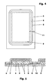
- FIGS. 4 and 5 show a transdermal therapeutic patch in plan view and in cross section.
- the plaster essentially comprises an active substance-containing reservoir film (1, 2), a protective film (5) and a rear film (6).
- the individual here rectangular reservoir film (1,2) consists for example of the active substance-containing pressure-sensitive adhesive layer (3) and a barrier layer (4). The latter prevents, inter alia, the rear path diffusion of the drug.
- the laminate of pressure-sensitive adhesive layer (3) and barrier layer (4) is centrally and adhesively on the protective film (5). In this case, the protective film (5) projects beyond the reservoir film (1, 2) at all edges.
- the rear film (6) provided with an adhesive layer (7).
- the adhesive layer (7) contacts the barrier layer (4) and the edge regions of the protective film (5).
- the protective film (5) and the rear film (6) surround the reservoir film (1, 2) in an active-substance-tight manner, with the protective film (5) projecting beyond the rear film (6) in the exemplary embodiment.
- FIGS. 1 to 3 show areas of processing stations where some process steps for plaster packaging take place.
- a first station is the synchronization station (30), cf. FIG. 1 ,
- This station comprises an example on two rollers (35, 36) guided and driven transport element (33).
- the latter is here an endless conveyor belt, for example, a thin-walled fluorosilicone coated metal foil. Seen in the longitudinal direction (19) are located behind the conveyor belt (33) has a non-driven axle (21) on which two film rolls (23, 24) are mounted.
- Each film roll (23, 24) consists of a very long, narrow wound reservoir film web (15, 16). Since the reservoir film webs (15, 16) are also packaged or assembled on single-track systems, the rollers (15, 16) usually have different diameters when restarting a batch on a multi-track system.
- Each reservoir film web (15, 16) is fed to the conveyor belt (33) with the adhesive adhesive layer (3) down and applied there by means of the first pressure roller (31).
- the system creates a temporarily adhering connection with the conveyor belt (33).
- the reservoir film webs (15, 16) only by the pulling movement of the conveyor belt (33) Synchronously transported parallel to each other.
- the two reservoir film webs (15, 16) for example, have a distance which corresponds to the double edge region (11) of the protective film (5).
- the conveyor belt (33) is wider than the sum of the juxtaposed reservoir film webs (15, 16) including the web interspaces.
- a cylindrical roller can be used.
- the pendulum buffers (25, 26) from the Figures 2 and 3 are in for simplicity FIG. 1 not shown.
- a transport element (34) which provides a disposable plastic film instead of the endless conveyor belt (33).
- This auxiliary film (34) for example a siliconized polyester film, is unwound from a driven donor roll (41), passes through a first buffer loop (43), wraps around a first and second deflection roller (35, 36), passes through a second buffer loop (47) and becomes finally wound up again on a driven collecting roller (45).
- the second deflection roller (36) generates the transport feed.
- a pressure roller (38) extends through its position below the deflection roller (36) the loop of the plastic film (34).
- the buffer loops (43, 47), which compensate for the discontinuous auxiliary foil movement by their up and down movements and thus protect the drives of the rollers (41, 45) against changes in acceleration, are tensioned, for example, by weight-loaded tension rollers (44, 48).
- a separating device (50) is shown only schematically, cf. FIG. 3.
- the latter separates the respective reservoir foils (1, 2) from the ones with a separating tool, for example a cutting knife (51), oriented here transversely to the longitudinal direction (19), for example corresponding Reservoirfolienbahnen (15, 16) from.
- a separating tool for example a cutting knife (51), oriented here transversely to the longitudinal direction (19), for example corresponding Reservoirfolienbahnen (15, 16) from.
- an eccentric or separating drive (52, 53) acts on the knife (51).
- the return stroke of the knife (51) causes a spring element (55).
- the cutting blade (51) and the drive (52, 53) are part of a carriage (56), which is moved according to the embodiment during the cutting process at least in regions synchronously with the transport element (33, 34).
- the separation movement also take place in the feed pause of the transport element (33, 34).
- the carriage (56) remains - without sliding or roller-mounted longitudinal guide - stationary relative to the synchronization station (30).
- a compensating buffer element can be arranged between the separating drive (52, 53) and the separating tool (51) in order not to mechanically damage the corresponding transport element (33, 34) during the separating process.
- optical or hydraulic separation process eliminates such an element.
- the protective film (5) Downstream of the synchronization station (30) is a packaging station (60).
- the protective film (5) is covered by e.g. unwinded protective film roll (61) unwound and pulled after a deflection by the transport roller (62) by means of a feed-generating device, not shown, in the longitudinal direction (19).
- the pressure-sensitive adhesive reservoir films (1, 2) - in the exemplary embodiment in pairs - passed. There they are rolled over at least one pressure roller (63) on the protective film (5).
- the rear film (7) is brought to the new composite of protective film (5) and resting reservoir films (1, 2).
- Those of a e.g. non-driven rear roller (65) unwound rear sheet (7) with its downwardly oriented adhesive layer (6) u.a. by means of the pressure roller (66) on the composite (1, 2, 5) tightly adhered.
- edges (8) of the backsheet (7) are cut and deducted the resulting grid-shaped back sheet remnants.
- the plasters are separated by cutting the protective film edges (12).
- the Mehrnutztechnik or multi-track of the method is shown on a two-lane system. Depending on the pavement width, such systems can easily be upgraded to eg 10 or even more tracks.
Abstract
Description
Die Erfindung betrifft ein Verfahren zum mehrspurigen Konfektionieren transdermaler therapeutischer Pflaster mit einer mindestens einlagigen, wirkstoffhaltigen und haftklebenden Reservoirfolie, die zwischen einer Rückfolie und einer ablösbaren Schutzfolie angeordnet wird.The invention relates to a method for the multilane finishing of transdermal therapeutic patches with an at least single-layer, active substance-containing and pressure-sensitive adhesive reservoir film which is arranged between a backsheet and a removable protective film.
Transdermale therapeutische Pflaster sind auf die Haut aufzubringende Arzneiformen mit dem Aussehen traditioneller Pflaster. Die Pflaster enthalten mindestens einen über die Haut abzugebenden Arzneistoff. Die Arzneistoffe werden in vorbestimmter Rate kontinuierlich über einen festgelegten Zeitraum an einem festgelegten Anwendungsort auf der Körperhaut abgegeben.Transdermal therapeutic patches are skin-applied dosage forms with the appearance of traditional patches. The patches contain at least one drug to be delivered through the skin. The drugs are delivered at a predetermined rate continuously over a predetermined period of time at a predetermined site of application on the body skin.
Derartige Pflaster haben in der Regel einfache geometrische Formen. Sie sind in der Draufsicht gesehen z.B. rechteckig oder rautenförmig. Das Pflaster selbst besteht z.B. aus einem wirkstoffhaltigen Folienreservoir mit einer zur Haut hin orientierten Klebeschicht. Auch die Klebeschicht kann zusätzlich Arzneistoff tragen. Das Folienreservoir ist verpackt zwischen einer ablösbaren Schutzfolie und einer zur Schutzfolie hin klebenden Rückfolie. Letztere verhindert, dass Dritte bei einem unbeabsichtigten Pflasterkontakt Wirkstoffe aufnehmen können.Such patches usually have simple geometric shapes. They are seen in plan view e.g. rectangular or diamond-shaped. The plaster itself consists e.g. from a drug-containing film reservoir with a skin-oriented adhesive layer. The adhesive layer can also carry additional drug. The film reservoir is packaged between a removable protective film and a backing film adhering to the protective film. The latter prevents third parties from taking up active substances in the event of unintentional patch contact.
Derartige Pflaster werden bisher nach einem aus der
Der vorliegenden Erfindung liegt daher die Problemstellung zugrunde, ein Verfahren zum mehrspurigen Konfektionieren zu entwickeln, bei dem von Rollen abwickelbare bahnförmige Reservoirfolien verwendet werden können, ohne wirkstoffhaltige Abfälle zu erzeugen.The present invention is therefore based on the problem to develop a method for multi-lane packaging, can be used in the roll-developable web-shaped reservoir films without producing active substance-containing waste.
Diese Problemstellung wird mit den Merkmalen des Hauptanspruches gelöst. Hierbei liegt pro Konfektionierungsspur die Reservoirfolie jeweils als Reservoirfolienbahn auf einer Rolle aufgewickelt vor. Die Reservoirfolienbahnen werden pro Spur mit ihrer Haftklebeschicht auf ein diskontinuierlich in Längsrichtung der Reservoirfolienbahnen bewegtes Transportelement aufgelegt. Auf dem Transportelement werden die nebeneinander aufliegenden Reservoirfolienbahnen quer oder schräg zur Längsrichtung zumindest annähernd zeitgleich in einzelnen Reservoirfolien mit Hilfe einer Trennvorrichtung abgetrennt. Anschließend werden die jeweils paarweise nebeneinander liegenden Reservoirfolien am Transportelementende an ein kontinuierlich bewegtes weiteres Transportelement zur beabstandenden Ablage übergeben. Nach der Übergabe der vorderen Reservoirfolien wird das abgebende Transportelement kurz abgebremst.This problem is solved with the features of the main claim. In this case, the reservoir film per wound on a reel is in each case wound on a reel as a reservoir film web. The reservoir film webs are applied per track with their pressure-sensitive adhesive layer to a transport element that is moved discontinuously in the longitudinal direction of the reservoir film webs. On the transport element, the juxtaposed reservoir foil webs are separated transversely or obliquely to the longitudinal direction at least approximately simultaneously in individual reservoir foils with the aid of a separating device. Subsequently, the pairs of adjacent reservoir films are at the end of the transport element passed to a continuously moving further transport element for spacing storage. After the transfer of the front reservoir films, the donating transport element is briefly braked.
Weitere Einzelheiten der Erfindung ergeben sich aus den Unteransprüchen und der nachfolgenden Beschreibung eines schematisch dargestellten Ausführungsbeispiels.
- Figur 1:
- Synchronisationsstation für z.B. zwei schmale Rollen;
- Figur 2:
- Synchronisationsstation mit Einmaltransportfolie sowie Schneidevorrichtung und Verpackungsstation;
- Figur 3:
- wie
Figur 2 - Figur 4:
- Draufsicht auf ein fertig verpacktes Pflaster;
- Figur 5:
- Querschnitt durch aneinander gereihte, noch ungetrennte Pflaster.
- FIG. 1:
- Synchronization station for eg two narrow rollers;
- FIG. 2:
- Synchronization station with disposable transport foil as well as cutting device and packing station;
- FIG. 3:
- as
FIG. 2 but synchronization station with an endless conveyor belt; - FIG. 4:
- Top view of a ready-packed plaster;
- FIG. 5:
- Cross section through rows of patches that are still unseparated.
Die
Das Pflaster umfasst im Wesentlichen eine wirkstoffhaltige Reservoirfolie (1, 2), eine Schutzfolie (5) und eine Rückfolie (6). Die einzelne hier rechteckige Reservoirfolie (1,2) besteht beispielsweise aus der wirkstoffhaltigen Haftklebeschicht (3) und einer Sperrschicht (4). Letztere verhindert u.a. die rückseitige Wegdiffusion des Wirkstoffs. Das Laminat aus Haftklebeschicht (3) und Sperrschicht (4) liegt mittig und klebend auf der Schutzfolie (5) auf. Hierbei steht die Schutzfolie (5) an allen Rändern über die Reservoirfolie (1, 2) über.The plaster essentially comprises an active substance-containing reservoir film (1, 2), a protective film (5) and a rear film (6). The individual here rectangular reservoir film (1,2) consists for example of the active substance-containing pressure-sensitive adhesive layer (3) and a barrier layer (4). The latter prevents, inter alia, the rear path diffusion of the drug. The laminate of pressure-sensitive adhesive layer (3) and barrier layer (4) is centrally and adhesively on the protective film (5). In this case, the protective film (5) projects beyond the reservoir film (1, 2) at all edges.
Über der Reservoirfolie (1, 2) liegt die mit einer Klebeschicht (7) ausgestattete Rückfolie (6). Die Klebeschicht (7) kontaktiert hierbei die Sperrschicht (4) und die Randbereiche der Schutzfolie (5). Die Schutzfolie (5) und die Rückfolie (6) umschließen die Reservoirfolie (1, 2) wirkstoffdicht, wobei die Schutzfolie (5) im Ausführungsbeispiel über die Rückfolie (6) übersteht.Above the reservoir film (1, 2) is the rear film (6) provided with an adhesive layer (7). The adhesive layer (7) contacts the barrier layer (4) and the edge regions of the protective film (5). The protective film (5) and the rear film (6) surround the reservoir film (1, 2) in an active-substance-tight manner, with the protective film (5) projecting beyond the rear film (6) in the exemplary embodiment.
Um derartige Pflaster kostengünstig herstellen zu können, sind mehrnutzige bzw. mehrspurige Verpackungsanlagen erforderlich. Die
Eine erste Station ist die Synchronisationsstation (30), vgl.
Jeder Reservoirfolienbahn (15, 16) wird dem Transportband (33) mit der klebenden Haftschicht (3) nach unten zugeführt und mittels der ersten Andruckrolle (31) dort angelegt. Bei der Anlage entsteht eine temporär haftende Verbindung mit dem Transportband (33). In der Folge werden die Reservoirfolienbahnen (15, 16) nur durch die ziehende Bewegung des Transportbandes (33) synchron parallel zueinander befördert. Auf dem Transportband (33) haben die beiden Reservoirfolienbahnen (15, 16) z.B. einen Abstand, der dem doppelten Randbereich (11) der Schutzfolie (5) entspricht. Das Transportband (33) ist breiter als die Summe der nebeneinander aufliegenden Reservoirfolienbahnen (15, 16) einschließlich der Bahnzwischenräume. Anstelle des endlosen Transportbandes (33) kann auch eine zylindrische Walze verwendet werden.Each reservoir film web (15, 16) is fed to the conveyor belt (33) with the adhesive adhesive layer (3) down and applied there by means of the first pressure roller (31). The system creates a temporarily adhering connection with the conveyor belt (33). As a result, the reservoir film webs (15, 16) only by the pulling movement of the conveyor belt (33) Synchronously transported parallel to each other. On the conveyor belt (33), the two reservoir film webs (15, 16), for example, have a distance which corresponds to the double edge region (11) of the protective film (5). The conveyor belt (33) is wider than the sum of the juxtaposed reservoir film webs (15, 16) including the web interspaces. Instead of the endless conveyor belt (33) and a cylindrical roller can be used.
Die Pendelpuffer (25, 26) aus den
In
Oberhalb der Synchronisationsstation (30) ist eine nur schematisch dargestellte Trennvorrichtung (50) angeordnet, vgl. Figur 3. Letztere trennt mit einem hier z.B. quer zur Längsrichtung (19) ausgerichteten Trennwerkzeug, beispielsweise einem Schneidmesser (51) die jeweiligen Reservoirfolien (1, 2) von den entsprechenden Reservoirfolienbahnen (15, 16) ab. Für die Trennbewegung des Scheidmessers (51) wirkt ein Exzenter- bzw. Trennantrieb (52, 53) auf das Messer (51). Den Rückhub des Messers (51) bewirkt ein Federelement (55). Das Schneidmesser (51) und der Antrieb (52, 53) sind Teil eines Schlittens (56), der nach dem Ausführungsbeispiel während des Scheidvorganges zumindest bereichsweise synchron zum Transportelement (33, 34) bewegt wird.Above the synchronization station (30), a separating device (50) is shown only schematically, cf. FIG. 3. The latter separates the respective reservoir foils (1, 2) from the ones with a separating tool, for example a cutting knife (51), oriented here transversely to the longitudinal direction (19), for example corresponding Reservoirfolienbahnen (15, 16) from. For the separating movement of the cutting blade (51), an eccentric or separating drive (52, 53) acts on the knife (51). The return stroke of the knife (51) causes a spring element (55). The cutting blade (51) and the drive (52, 53) are part of a carriage (56), which is moved according to the embodiment during the cutting process at least in regions synchronously with the transport element (33, 34).
Selbstverständlich kann die Trennbewegung auch in der Vorschubpause des Transportelements (33, 34) stattfinden. In diesem Fall verharrt der Schlitten (56) - ohne gleit- oder wälzgelagerte Längsführung - ortsfest gegenüber der Synchronisationsstation (30).Of course, the separation movement also take place in the feed pause of the transport element (33, 34). In this case, the carriage (56) remains - without sliding or roller-mounted longitudinal guide - stationary relative to the synchronization station (30).
Werden für den Trennvorgang mechanische Stanz- oder Schneidwerkzeuge eingesetzt, so kann zwischen dem Trennantrieb (52, 53) und dem Trennwerkzeug (51) ein Ausgleichspufferelement angeordnet werden, um beim Trennvorgang das entsprechende Transportelement (33, 34) nicht mechanisch zu beschädigen. Bei optischen oder hydraulischen Trennverfahren entfällt ein derartiges Element.If mechanical punching or cutting tools are used for the separation process, then a compensating buffer element can be arranged between the separating drive (52, 53) and the separating tool (51) in order not to mechanically damage the corresponding transport element (33, 34) during the separating process. In optical or hydraulic separation process eliminates such an element.
In den
Der Synchronisationsstation (30) nachgeschaltet ist eine Verpackungsstation (60). In dieser wird die Schutzfolie (5) von einer z.B. nicht angetriebenen Schutzfolienrolle (61) abgewickelt und nach einer Umlenkung durch die Transportrolle (62) mit Hilfe einer nicht dargestellten einen Vorschub erzeugenden Einrichtung in Längsrichtung (19) gezogen. Auf die sich beispielsweise kontinuierlich bewegende Schutzfolie (5) werden die haftklebenden Reservoirfolien (1, 2) - im Ausführungsbeispiel paarweise - übergeben. Dort werden sie über mindestens eine Anpresswalze (63) auf die Schutzfolie (5) aufgewalzt.Downstream of the synchronization station (30) is a packaging station (60). In this, the protective film (5) is covered by e.g. unwinded protective film roll (61) unwound and pulled after a deflection by the transport roller (62) by means of a feed-generating device, not shown, in the longitudinal direction (19). On the example, continuously moving protective film (5), the pressure-sensitive adhesive reservoir films (1, 2) - in the exemplary embodiment in pairs - passed. There they are rolled over at least one pressure roller (63) on the protective film (5).
Durch die Abstimmung der Bewegungen des Transportelements (33, 34) und der Schutzfolie (5) wird zwischen den vereinzelten Reservoirfolien (1, 2) ein konstanter Abstand erzeugt.By coordinating the movements of the transport element (33, 34) and the protective film (5), a constant distance is created between the separated reservoir films (1, 2).
Hinter der Anpresswalze (63) wird die Rückfolie (7) an den neuen Verbund aus Schutzfolie (5) und aufliegenden Reservoirfolien (1, 2) herangeführt. Die von einer z.B. nicht angetriebenen Rückfolienrolle (65) abgewickelte Rückfolie (7) wird mit ihrer nach unten orientierten Klebeschicht (6) u.a. mittels der Anpresswalze (66) auf den Verbund (1, 2; 5) dicht aufgeklebt.Behind the pressure roller (63), the rear film (7) is brought to the new composite of protective film (5) and resting reservoir films (1, 2). Those of a e.g. non-driven rear roller (65) unwound rear sheet (7) with its downwardly oriented adhesive layer (6) u.a. by means of the pressure roller (66) on the composite (1, 2, 5) tightly adhered.
In weiteren Stationen werden die Ränder (8) der Rückfolie (7) geschnitten und die hierbei entstehenden gitterförmigen Rückfolienreste abgezogen. In einem weiteren Schritt werden die Pflaster durch Schneiden der Schutzfolienränder (12) vereinzelt.In further stations, the edges (8) of the backsheet (7) are cut and deducted the resulting grid-shaped back sheet remnants. In a further step, the plasters are separated by cutting the protective film edges (12).
Im Ausführungsbeispiel wird die Mehrnutzigkeit bzw. die Mehrspurigkeit des Verfahrens an einer zweispurigen Anlage gezeigt. Je nach Pflasterbreite können derartige Anlagen problemlos auch auf z.B. 10 oder noch mehr Spuren umgerüstet werden.In the embodiment, the Mehrnutzigkeit or multi-track of the method is shown on a two-lane system. Depending on the pavement width, such systems can easily be upgraded to eg 10 or even more tracks.
- 1, 21, 2
- Reservoirfolie, WirkstoffreservoirReservoir film, drug reservoir
- 33
- Haftklebeschicht von (1, 2)Pressure-sensitive adhesive layer of (1, 2)
- 44
- Sperrschicht von (1, 2)Barrier layer of (1, 2)
- 55
- Schutzfolie, abziehbarProtective film, removable
- 66
- RückfolieBacking
- 77
- Klebeschicht von (6)Adhesive layer of (6)
- 88th
- Rand von (6)Edge of (6)
- 99
- Stanzlinie von (5)Punching line of (5)
- 1111
- Randbereichborder area
- 1212
- SchutzfolienrandProtective film edge
- 13, 1413, 14
- Konfektionierungsspurenfinishing tracks
- 15, 1615, 16
- ReservoirfolienbahnReservoir sheet
- 1717
- ReservoirfolienlängeReservoir film length
- 1919
- Längsrichtung, TransportrichtungLongitudinal direction, transport direction
- 2121
- Achseaxis
- 2323
- Rolle, Folienrolle, großRoll, roll of film, big
- 2424
- Rolle, Folienrolle, kleinRoll, film roll, small
- 25, 2625, 26
- Pendelpufferpendulum buffer
- 27, 2827, 28
- Umlenkrollenguide rollers
- 3030
- Synchronisationsstationsynchronization station
- 3131
- Andruckrolle, erste, obenPinch roller, first, top
- 3333
- Transportband, TransportelementConveyor belt, transport element
- 3434
- Hilfsfolie, TransportelementAuxiliary foil, transport element
- 3535
- Umlenkrolle, erstePulley, first
- 3636
- Umlenkrolle, zweite, angetriebenPulley, second, driven
- 37, 3837, 38
- Andruckrollen, untenPinch rollers, bottom
- 4141
- SpenderolleStrip roller
- 4242
- Umlenkrolleidler pulley
- 4343
- Pufferschleife, ersteBuffer loop, first
- 4444
- Spannrolleidler
- 4545
- Sammelrollecomposite role
- 4646
- Umlenkrolleidler pulley
- 4747
- Pufferschleife, zweiteBuffer loop, second
- 4848
- Spannrolleidler
- 5050
- Trennvorrichtungseparating device
- 5151
- Schneidmesser, Messer, TrennwerkzeugCutting knife, knife, cutting tool
- 5252
- Motor, Teil des TrennantriebsEngine, part of the separating drive
- 5353
- Exzenter, Teil des TrennantriebsEccentric, part of the separating drive
- 5555
- Federelement, RückholfederSpring element, return spring
- 5656
- Schlittencarriage
- 6060
- Verpackungsstationpacking station
- 6161
- SchutzfolienrolleProtective film role
- 6262
- Transportrolletransport roller
- 6363
- Anpresswalzepressure roller
- 6565
- RückfolienrolleBacking roll
- 6666
- Anpresswalzepressure roller
Claims (7)
- A method for multi-track production of transdermal therapeutic patches with in each case a pressure-sensitive adhesive reservoir film (1, 2) which comprises at least one layer and contains active substance and which is arranged between a backing film (30) and a removable protective film (20),- wherein the reservoir film (1, 2) for each production track (13, 14) is in each case wound as a reservoir film web (15, 16) on a roller (23, 24),- wherein the reservoir film webs (1, 2) for each track (13, 14) are placed with their pressure-sensitive adhesive layer (3) onto a conveyor element (33, 34) that is moved non-continuously in the longitudinal direction (19) of the reservoir film webs (15, 16),- wherein all the reservoir film webs (15, 16) lying next to one another on the conveyor element (33, 34) are separated off into individual reservoir films (1, 2) with the aid of a separating device (50), transversely or obliquely with respect to the longitudinal direction (19) and at least approximately simultaneously,- wherein the reservoir films (1, 2) each lying next to one another at the end of the conveyor element are transferred to a continuously moved additional conveyor element (5) and placed at intervals thereon,- wherein the conveyor element (33, 34) is briefly slowed down after the transfer of the reservoir films (1, 2).
- The method as claimed in claim 1, characterized in that the production tracks (13, 14) extend parallel to one another.
- The method as claimed in claim 1, characterized in that the individual reservoir film webs (15, 16) of the corresponding production tracks (13, 14) are pressed jointly onto the conveyor element (33, 34) by a pressure roller (31).
- The method as claimed in claim 3, characterized in that the individual reservoir film webs (15, 16) are deflected several times between the film rollers (23, 24) and the pressure roller (31) with the aid of film buffers (25, 26).
- The method as claimed in claim 1, characterized in that both conveyor elements (33, 34; 5) have the same speed of advance in the common phase of movement.
- The method as claimed in claim 1, characterized in that the separating device (50) is arranged on a carriage (56) mounted on rollers or slides and is moved together with the latter (56) in parallel and in some areas in synchrony with the conveyor element (33, 34).
- The method as claimed in claim 6, characterized in that, after the transfer of the reservoir films (1, 2) to the conveyor element (5), the separating device (50) travels back an average reservoir film length (17), with the conveyor element (33, 34) stationary, in order to begin with a new separating operation and a new advance movement of the conveyor element (33, 34).
Applications Claiming Priority (2)
| Application Number | Priority Date | Filing Date | Title |
|---|---|---|---|
| US96561607P | 2007-08-21 | 2007-08-21 | |
| PCT/EP2008/006678 WO2009024284A2 (en) | 2007-08-21 | 2008-08-14 | Method for the multi-track tailoring of transdermal therapeutic patches |
Publications (2)
| Publication Number | Publication Date |
|---|---|
| EP2178480A2 EP2178480A2 (en) | 2010-04-28 |
| EP2178480B1 true EP2178480B1 (en) | 2010-10-27 |
Family
ID=40342783
Family Applications (1)
| Application Number | Title | Priority Date | Filing Date |
|---|---|---|---|
| EP08785540A Not-in-force EP2178480B1 (en) | 2007-08-21 | 2008-08-14 | Method for the multi-track tailoring of transdermal therapeutic patches |
Country Status (7)
| Country | Link |
|---|---|
| US (1) | US8142594B2 (en) |
| EP (1) | EP2178480B1 (en) |
| JP (1) | JP2010536445A (en) |
| AT (1) | ATE485797T1 (en) |
| DE (1) | DE502008001671D1 (en) |
| ES (1) | ES2350416T3 (en) |
| WO (1) | WO2009024284A2 (en) |
Families Citing this family (5)
| Publication number | Priority date | Publication date | Assignee | Title |
|---|---|---|---|---|
| DE102011082458A1 (en) * | 2011-09-09 | 2013-03-14 | Acino Ag | loop Slicer |
| RS54864B1 (en) * | 2012-01-20 | 2016-10-31 | Acino Ag | Reduced loss of lattice material in patch manufacturing |
| JP5661212B1 (en) * | 2014-08-28 | 2015-01-28 | 株式会社シグマ | Adhesive tape manufacturing equipment |
| WO2021222215A1 (en) * | 2020-04-30 | 2021-11-04 | Kindeva Drug Delivery L.P. | Adhesive article and method of making same |
| CN114534877B (en) * | 2022-02-16 | 2023-03-31 | 河南李济堂医药科技有限公司 | Dong-minority herbal medicine production device for promoting pain rehabilitation and preparation method |
Family Cites Families (48)
| Publication number | Priority date | Publication date | Assignee | Title |
|---|---|---|---|---|
| US2372617A (en) * | 1942-12-31 | 1945-03-27 | James W Trew | Method of producing composite panels |
| US2789640A (en) * | 1953-04-09 | 1957-04-23 | Johnson & Johnson | Machine and process for cutting and conveying small patches |
| US3574026A (en) * | 1966-08-23 | 1971-04-06 | Compac Corp | Method and apparatus for fabricating label stock |
| US3620880A (en) * | 1969-04-07 | 1971-11-16 | Jerome H Lemelson | Apparatus and method for producing composite materials |
| US3707422A (en) * | 1970-10-19 | 1972-12-26 | Smithe Machine Co Inc F L | Patch cutting and application system for two independently timed patches on an envelope blank |
| IE53703B1 (en) * | 1982-12-13 | 1989-01-18 | Elan Corp Plc | Drug delivery device |
| US4789415A (en) * | 1983-01-24 | 1988-12-06 | Faasse Jr Adrian L | Pharmaceutical packaging machine |
| US4556441A (en) * | 1983-01-24 | 1985-12-03 | Faasse Jr Adrian L | Pharmaceutical packaging method |
| US4664736A (en) * | 1983-01-24 | 1987-05-12 | Faasse Jr Adrain L | Pharmaceutical packaging method |
| JPS62102934A (en) * | 1985-10-26 | 1987-05-13 | Yoshida Kogyo Kk <Ykk> | Cutting and connecting device for connection piece |
| US4666441A (en) * | 1985-12-17 | 1987-05-19 | Ciba-Geigy Corporation | Multicompartmentalized transdermal patches |
| US4782647A (en) * | 1987-10-08 | 1988-11-08 | Becton, Dickinson And Company | Flexible packaging and the method of production |
| IT1213748B (en) * | 1987-12-16 | 1989-12-29 | Giorgio Dotta | MACHINE FOR MANUFACTURING AND PACKAGING PATCHES |
| US5405486A (en) * | 1988-03-04 | 1995-04-11 | Noven Pharmaceuticals, Inc. | Apparatus for forming a transdermal drug device |
| DE4110027C2 (en) * | 1991-03-27 | 1996-08-29 | Lohmann Therapie Syst Lts | Process for packaging transdermal therapeutic patches |
| US5268179A (en) * | 1992-02-14 | 1993-12-07 | Ciba-Geigy Corporation | Ultrasonically sealed transdermal drug delivery systems |
| US5756117A (en) * | 1992-04-08 | 1998-05-26 | International Medical Asscociates, Inc. | Multidose transdermal drug delivery system |
| ES2108282T3 (en) * | 1992-06-02 | 1997-12-16 | Alza Corp | APPARATUS FOR THE IONTOPHORETICAL RELEASE OF PHARMACES. |
| DE4232279C1 (en) * | 1992-09-25 | 1993-10-21 | Lohmann Therapie Syst Lts | Transfer process for the production of transdermal therapeutic systems |
| JP3156419B2 (en) * | 1993-02-15 | 2001-04-16 | 松下電器産業株式会社 | Method of removing separator for protecting anisotropic conductive film |
| DE4316751C1 (en) * | 1993-05-19 | 1994-08-04 | Lohmann Therapie Syst Lts | Method and device for producing a transdermal therapy system for the administration of active substances to the skin in the form of a flat multi-chamber or multi-chamber channel system |
| US5938032A (en) * | 1993-09-30 | 1999-08-17 | Ivers-Lee Corporation | Tandem package with pinhole |
| DE4405296C1 (en) | 1994-02-19 | 1995-06-14 | Ludwig Dr Grader | Transdermal therapeutic equipment-production method |
| DE4406976C1 (en) * | 1994-03-03 | 1995-06-22 | Lohmann Therapie Syst Lts | Transfer of adhesive material sections |
| IL113034A (en) * | 1994-04-05 | 2000-02-17 | Astra Ab | Topical dressing |
| US5851549A (en) * | 1994-05-25 | 1998-12-22 | Becton Dickinson And Company | Patch, with system and apparatus for manufacture |
| KR960040444A (en) * | 1995-05-22 | 1996-12-17 | 수다 히데아키 | Manufacturing apparatus and manufacturing method of sheet package |
| DE19547691C1 (en) * | 1995-12-20 | 1997-04-24 | Lohmann Therapie Syst Lts | Continuous prodn. of transdermal therapeutic plaster |
| US5795433A (en) * | 1996-02-08 | 1998-08-18 | Niedermeyer; William P. | Method and apparatus for making apparel with folded seams |
| US6464818B1 (en) * | 1996-10-04 | 2002-10-15 | Tesa Ag | Method of wasteless punching of adhesive punched items |
| DE19652269C2 (en) * | 1996-12-16 | 2002-04-11 | Lohmann Therapie Syst Lts | Contours -TTS |
| DE19738855C2 (en) * | 1997-09-05 | 2001-01-04 | Lohmann Therapie Syst Lts | Transdermal therapeutic system with adhesive reservoir layer and unidirectional elastic back layer |
| DE19800682B4 (en) * | 1998-01-10 | 2004-07-08 | Lts Lohmann Therapie-Systeme Ag | Process for producing a primary packaging for film or wafer-shaped administration forms |
| GB2336310B (en) * | 1998-04-14 | 2003-09-10 | Stowic Resources Ltd | Method of manufacturing transdermal patches |
| DE19853737C2 (en) * | 1998-11-21 | 2003-03-06 | Lohmann Therapie Syst Lts | Method for dispensing flat structures |
| US6475514B1 (en) * | 1998-12-03 | 2002-11-05 | Andrew Blitzer | Athletic patch |
| DE19925339C2 (en) * | 1999-06-02 | 2003-02-27 | Lohmann Therapie Syst Lts | Method and device for producing a product from strip tape, in particular a medical and / or active substance-containing product and fillable containers or sealed edge bags |
| DE19946384A1 (en) * | 1999-09-28 | 2001-04-05 | Lohmann Therapie Syst Lts | Method and device for dispensing pressure-sensitive adhesive laminate sections from a movable primary to a movable secondary carrier web |
| KR20010036685A (en) * | 1999-10-11 | 2001-05-07 | 김윤 | Transdermal fentanyl delivery matrix system |
| US6221384B1 (en) * | 1999-11-05 | 2001-04-24 | Anthony C. Pagedas | Segmented transdermal dosage unit |
| ATE556683T1 (en) * | 2000-03-10 | 2012-05-15 | 3M Innovative Properties Co | METHOD FOR PRODUCING MEDICAL DRESSES WITH DIFFERENT ADHESIVES |
| US6682757B1 (en) * | 2000-11-16 | 2004-01-27 | Euro-Celtique, S.A. | Titratable dosage transdermal delivery system |
| JP2002336295A (en) * | 2001-05-15 | 2002-11-26 | Toyo Kagaku Kk | Device and method for manufacturing adhesive bandage |
| DE10301837A1 (en) * | 2003-01-20 | 2004-07-29 | Beiersdorf Ag | Process for the production of plasters |
| US7182955B2 (en) * | 2003-04-30 | 2007-02-27 | 3M Innovative Properties Company | Abuse-resistant transdermal dosage form |
| EP2073893A2 (en) * | 2006-09-29 | 2009-07-01 | Koninklijke Philips Electronics N.V. | Electrically activated gel array for transdermal drug delivery |
| US20080107719A1 (en) * | 2006-11-08 | 2008-05-08 | Sukhon Likitlersuang | Transdermal drug delivery system |
| CA2719090A1 (en) * | 2008-04-25 | 2009-10-29 | Lts Lohmann Therapie-Systeme Ag | Patch transfer and inspection device |
-
2008
- 2008-08-14 AT AT08785540T patent/ATE485797T1/en active
- 2008-08-14 DE DE502008001671T patent/DE502008001671D1/en active Active
- 2008-08-14 JP JP2010521343A patent/JP2010536445A/en not_active Ceased
- 2008-08-14 EP EP08785540A patent/EP2178480B1/en not_active Not-in-force
- 2008-08-14 ES ES08785540T patent/ES2350416T3/en active Active
- 2008-08-14 WO PCT/EP2008/006678 patent/WO2009024284A2/en active Application Filing
-
2010
- 2010-01-19 US US12/657,317 patent/US8142594B2/en not_active Expired - Fee Related
Also Published As
| Publication number | Publication date |
|---|---|
| US20100122765A1 (en) | 2010-05-20 |
| WO2009024284A2 (en) | 2009-02-26 |
| ES2350416T3 (en) | 2011-01-21 |
| EP2178480A2 (en) | 2010-04-28 |
| WO2009024284A3 (en) | 2009-05-07 |
| DE502008001671D1 (en) | 2010-12-09 |
| US8142594B2 (en) | 2012-03-27 |
| ATE485797T1 (en) | 2010-11-15 |
| JP2010536445A (en) | 2010-12-02 |
Similar Documents
| Publication | Publication Date | Title |
|---|---|---|
| EP1131260B1 (en) | Method and device for dispensing flat forms | |
| DE60131885T2 (en) | ROLLING SYSTEM FOR RAIL-MATERIAL MATERIAL AND DEVICE FOR PUTTING RAIL-MATERIAL MATERIAL | |
| EP2178480B1 (en) | Method for the multi-track tailoring of transdermal therapeutic patches | |
| DE3022525C2 (en) | Method and device for applying a sticker to an endless web | |
| DE3444331A1 (en) | METHOD AND DEVICE FOR APPLYING ELASTIC TAPES ON A MATERIAL RAIL | |
| DE3114470A1 (en) | DEVICE FOR FEEDING SHEETS FROM A Wrapping Material TO A PACKING MACHINE | |
| DE3713666C2 (en) | Embossing method and embossing rotary machine | |
| DE102015108702A1 (en) | Semi-pre-cut, double-sided tape product and method of making the same | |
| DE202010013513U1 (en) | packaging machine | |
| DE19502441A1 (en) | Method and device for applying labels | |
| DE7137380U (en) | DEVICE FOR APPLYING GRAINY MATERIAL | |
| EP3156251B1 (en) | Method for applying at least one enclosing element to a flat product composition, and enclosing element applying device for carrying out the method | |
| DE3234556A1 (en) | Labelling device for the preparation of labels and application thereof to packages or the like | |
| DE2516373A1 (en) | Disposable diapers from laminate of permeable and impermeable layers - enclosing absorbent layer with transverse edges formed by bond lines | |
| DE2111160A1 (en) | Device for conveying metallized strips in a plate press | |
| EP1539583A1 (en) | Method and device for producing a primary individual packing of a wafer | |
| DE3905469A1 (en) | DEVICE FOR APPLYING REINFORCEMENT LABELS PROVIDED WITH A GLUE APPLICATION ON A CROSS-PERFORATED RAIL | |
| DE2654932C2 (en) | Apparatus for making paper cylinders for growing seams | |
| CH704967A1 (en) | Method for attaching strip on planar product e.g. compact disk, involves moving selected edge of product past a specified point, to drive strip that is held ready at specific point of transporting path | |
| EP1394091A1 (en) | Method and device for supplying a printer with single sheets | |
| DE4127102A1 (en) | Counted paper sheet marking - in which adhesive strips are applied to sheets at counted intervals to mark quantities in paper stacks | |
| DE3614917A1 (en) | Method and apparatus for the packaging of products | |
| DE1303722B (en) | ||
| DE1044704B (en) | Device for applying tear strips to a web of wrapping material | |
| DE1629779A1 (en) | Method and device for inserting and fixing paper inlays or the like between two thermoplastic film webs, in particular for manufacturing tobacco pouches |
Legal Events
| Date | Code | Title | Description |
|---|---|---|---|
| PUAI | Public reference made under article 153(3) epc to a published international application that has entered the european phase |
Free format text: ORIGINAL CODE: 0009012 |
|
| 17P | Request for examination filed |
Effective date: 20091212 |
|
| AK | Designated contracting states |
Kind code of ref document: A2 Designated state(s): AT BE BG CH CY CZ DE DK EE ES FI FR GB GR HR HU IE IS IT LI LT LU LV MC MT NL NO PL PT RO SE SI SK TR |
|
| AX | Request for extension of the european patent |
Extension state: AL BA MK RS |
|
| GRAP | Despatch of communication of intention to grant a patent |
Free format text: ORIGINAL CODE: EPIDOSNIGR1 |
|
| DAX | Request for extension of the european patent (deleted) | ||
| GRAS | Grant fee paid |
Free format text: ORIGINAL CODE: EPIDOSNIGR3 |
|
| GRAA | (expected) grant |
Free format text: ORIGINAL CODE: 0009210 |
|
| AK | Designated contracting states |
Kind code of ref document: B1 Designated state(s): AT BE BG CH CY CZ DE DK EE ES FI FR GB GR HR HU IE IS IT LI LT LU LV MC MT NL NO PL PT RO SE SI SK TR |
|
| REG | Reference to a national code |
Ref country code: GB Ref legal event code: FG4D Free format text: NOT ENGLISH |
|
| REG | Reference to a national code |
Ref country code: CH Ref legal event code: EP |
|
| REG | Reference to a national code |
Ref country code: IE Ref legal event code: FG4D Free format text: LANGUAGE OF EP DOCUMENT: GERMAN |
|
| REF | Corresponds to: |
Ref document number: 502008001671 Country of ref document: DE Date of ref document: 20101209 Kind code of ref document: P |
|
| REG | Reference to a national code |
Ref country code: ES Ref legal event code: FG2A Effective date: 20110111 |
|
| REG | Reference to a national code |
Ref country code: NL Ref legal event code: VDEP Effective date: 20101027 |
|
| LTIE | Lt: invalidation of european patent or patent extension |
Effective date: 20101027 |
|
| PG25 | Lapsed in a contracting state [announced via postgrant information from national office to epo] |
Ref country code: LT Free format text: LAPSE BECAUSE OF FAILURE TO SUBMIT A TRANSLATION OF THE DESCRIPTION OR TO PAY THE FEE WITHIN THE PRESCRIBED TIME-LIMIT Effective date: 20101027 Ref country code: NO Free format text: LAPSE BECAUSE OF FAILURE TO SUBMIT A TRANSLATION OF THE DESCRIPTION OR TO PAY THE FEE WITHIN THE PRESCRIBED TIME-LIMIT Effective date: 20110127 |
|
| REG | Reference to a national code |
Ref country code: IE Ref legal event code: FD4D |
|
| PG25 | Lapsed in a contracting state [announced via postgrant information from national office to epo] |
Ref country code: LV Free format text: LAPSE BECAUSE OF FAILURE TO SUBMIT A TRANSLATION OF THE DESCRIPTION OR TO PAY THE FEE WITHIN THE PRESCRIBED TIME-LIMIT Effective date: 20101027 Ref country code: SE Free format text: LAPSE BECAUSE OF FAILURE TO SUBMIT A TRANSLATION OF THE DESCRIPTION OR TO PAY THE FEE WITHIN THE PRESCRIBED TIME-LIMIT Effective date: 20101027 Ref country code: IS Free format text: LAPSE BECAUSE OF FAILURE TO SUBMIT A TRANSLATION OF THE DESCRIPTION OR TO PAY THE FEE WITHIN THE PRESCRIBED TIME-LIMIT Effective date: 20110227 Ref country code: FI Free format text: LAPSE BECAUSE OF FAILURE TO SUBMIT A TRANSLATION OF THE DESCRIPTION OR TO PAY THE FEE WITHIN THE PRESCRIBED TIME-LIMIT Effective date: 20101027 Ref country code: SI Free format text: LAPSE BECAUSE OF FAILURE TO SUBMIT A TRANSLATION OF THE DESCRIPTION OR TO PAY THE FEE WITHIN THE PRESCRIBED TIME-LIMIT Effective date: 20101027 Ref country code: BG Free format text: LAPSE BECAUSE OF FAILURE TO SUBMIT A TRANSLATION OF THE DESCRIPTION OR TO PAY THE FEE WITHIN THE PRESCRIBED TIME-LIMIT Effective date: 20110127 Ref country code: NL Free format text: LAPSE BECAUSE OF FAILURE TO SUBMIT A TRANSLATION OF THE DESCRIPTION OR TO PAY THE FEE WITHIN THE PRESCRIBED TIME-LIMIT Effective date: 20101027 Ref country code: PT Free format text: LAPSE BECAUSE OF FAILURE TO SUBMIT A TRANSLATION OF THE DESCRIPTION OR TO PAY THE FEE WITHIN THE PRESCRIBED TIME-LIMIT Effective date: 20110228 Ref country code: HR Free format text: LAPSE BECAUSE OF FAILURE TO SUBMIT A TRANSLATION OF THE DESCRIPTION OR TO PAY THE FEE WITHIN THE PRESCRIBED TIME-LIMIT Effective date: 20101027 |
|
| PG25 | Lapsed in a contracting state [announced via postgrant information from national office to epo] |
Ref country code: GR Free format text: LAPSE BECAUSE OF FAILURE TO SUBMIT A TRANSLATION OF THE DESCRIPTION OR TO PAY THE FEE WITHIN THE PRESCRIBED TIME-LIMIT Effective date: 20110128 |
|
| PG25 | Lapsed in a contracting state [announced via postgrant information from national office to epo] |
Ref country code: EE Free format text: LAPSE BECAUSE OF FAILURE TO SUBMIT A TRANSLATION OF THE DESCRIPTION OR TO PAY THE FEE WITHIN THE PRESCRIBED TIME-LIMIT Effective date: 20101027 Ref country code: CZ Free format text: LAPSE BECAUSE OF FAILURE TO SUBMIT A TRANSLATION OF THE DESCRIPTION OR TO PAY THE FEE WITHIN THE PRESCRIBED TIME-LIMIT Effective date: 20101027 Ref country code: IE Free format text: LAPSE BECAUSE OF FAILURE TO SUBMIT A TRANSLATION OF THE DESCRIPTION OR TO PAY THE FEE WITHIN THE PRESCRIBED TIME-LIMIT Effective date: 20101027 |
|
| PG25 | Lapsed in a contracting state [announced via postgrant information from national office to epo] |
Ref country code: SK Free format text: LAPSE BECAUSE OF FAILURE TO SUBMIT A TRANSLATION OF THE DESCRIPTION OR TO PAY THE FEE WITHIN THE PRESCRIBED TIME-LIMIT Effective date: 20101027 Ref country code: DK Free format text: LAPSE BECAUSE OF FAILURE TO SUBMIT A TRANSLATION OF THE DESCRIPTION OR TO PAY THE FEE WITHIN THE PRESCRIBED TIME-LIMIT Effective date: 20101027 Ref country code: PL Free format text: LAPSE BECAUSE OF FAILURE TO SUBMIT A TRANSLATION OF THE DESCRIPTION OR TO PAY THE FEE WITHIN THE PRESCRIBED TIME-LIMIT Effective date: 20101027 Ref country code: RO Free format text: LAPSE BECAUSE OF FAILURE TO SUBMIT A TRANSLATION OF THE DESCRIPTION OR TO PAY THE FEE WITHIN THE PRESCRIBED TIME-LIMIT Effective date: 20101027 |
|
| PLBE | No opposition filed within time limit |
Free format text: ORIGINAL CODE: 0009261 |
|
| STAA | Information on the status of an ep patent application or granted ep patent |
Free format text: STATUS: NO OPPOSITION FILED WITHIN TIME LIMIT |
|
| 26N | No opposition filed |
Effective date: 20110728 |
|
| REG | Reference to a national code |
Ref country code: DE Ref legal event code: R097 Ref document number: 502008001671 Country of ref document: DE Effective date: 20110728 |
|
| PG25 | Lapsed in a contracting state [announced via postgrant information from national office to epo] |
Ref country code: MT Free format text: LAPSE BECAUSE OF FAILURE TO SUBMIT A TRANSLATION OF THE DESCRIPTION OR TO PAY THE FEE WITHIN THE PRESCRIBED TIME-LIMIT Effective date: 20101027 |
|
| BERE | Be: lapsed |
Owner name: LTS LOHMANN THERAPIE-SYSTEME A.G. Effective date: 20110831 |
|
| PG25 | Lapsed in a contracting state [announced via postgrant information from national office to epo] |
Ref country code: MC Free format text: LAPSE BECAUSE OF NON-PAYMENT OF DUE FEES Effective date: 20110831 |
|
| PG25 | Lapsed in a contracting state [announced via postgrant information from national office to epo] |
Ref country code: BE Free format text: LAPSE BECAUSE OF NON-PAYMENT OF DUE FEES Effective date: 20110831 |
|
| REG | Reference to a national code |
Ref country code: CH Ref legal event code: PL |
|
| PG25 | Lapsed in a contracting state [announced via postgrant information from national office to epo] |
Ref country code: LI Free format text: LAPSE BECAUSE OF NON-PAYMENT OF DUE FEES Effective date: 20120831 Ref country code: CH Free format text: LAPSE BECAUSE OF NON-PAYMENT OF DUE FEES Effective date: 20120831 |
|
| PG25 | Lapsed in a contracting state [announced via postgrant information from national office to epo] |
Ref country code: LU Free format text: LAPSE BECAUSE OF NON-PAYMENT OF DUE FEES Effective date: 20110814 Ref country code: CY Free format text: LAPSE BECAUSE OF EXPIRATION OF PROTECTION Effective date: 20101027 |
|
| PG25 | Lapsed in a contracting state [announced via postgrant information from national office to epo] |
Ref country code: TR Free format text: LAPSE BECAUSE OF FAILURE TO SUBMIT A TRANSLATION OF THE DESCRIPTION OR TO PAY THE FEE WITHIN THE PRESCRIBED TIME-LIMIT Effective date: 20101027 |
|
| PG25 | Lapsed in a contracting state [announced via postgrant information from national office to epo] |
Ref country code: HU Free format text: LAPSE BECAUSE OF FAILURE TO SUBMIT A TRANSLATION OF THE DESCRIPTION OR TO PAY THE FEE WITHIN THE PRESCRIBED TIME-LIMIT Effective date: 20101027 |
|
| PGFP | Annual fee paid to national office [announced via postgrant information from national office to epo] |
Ref country code: DE Payment date: 20130821 Year of fee payment: 6 Ref country code: ES Payment date: 20130829 Year of fee payment: 6 |
|
| PGFP | Annual fee paid to national office [announced via postgrant information from national office to epo] |
Ref country code: FR Payment date: 20130823 Year of fee payment: 6 Ref country code: GB Payment date: 20130821 Year of fee payment: 6 |
|
| PGFP | Annual fee paid to national office [announced via postgrant information from national office to epo] |
Ref country code: IT Payment date: 20130827 Year of fee payment: 6 |
|
| REG | Reference to a national code |
Ref country code: AT Ref legal event code: MM01 Ref document number: 485797 Country of ref document: AT Kind code of ref document: T Effective date: 20130814 |
|
| PG25 | Lapsed in a contracting state [announced via postgrant information from national office to epo] |
Ref country code: AT Free format text: LAPSE BECAUSE OF NON-PAYMENT OF DUE FEES Effective date: 20130814 |
|
| REG | Reference to a national code |
Ref country code: DE Ref legal event code: R119 Ref document number: 502008001671 Country of ref document: DE |
|
| GBPC | Gb: european patent ceased through non-payment of renewal fee |
Effective date: 20140814 |
|
| PG25 | Lapsed in a contracting state [announced via postgrant information from national office to epo] |
Ref country code: IT Free format text: LAPSE BECAUSE OF NON-PAYMENT OF DUE FEES Effective date: 20140814 |
|
| REG | Reference to a national code |
Ref country code: DE Ref legal event code: R119 Ref document number: 502008001671 Country of ref document: DE Effective date: 20150303 |
|
| REG | Reference to a national code |
Ref country code: FR Ref legal event code: ST Effective date: 20150430 |
|
| PG25 | Lapsed in a contracting state [announced via postgrant information from national office to epo] |
Ref country code: GB Free format text: LAPSE BECAUSE OF NON-PAYMENT OF DUE FEES Effective date: 20140814 Ref country code: DE Free format text: LAPSE BECAUSE OF NON-PAYMENT OF DUE FEES Effective date: 20150303 |
|
| PG25 | Lapsed in a contracting state [announced via postgrant information from national office to epo] |
Ref country code: FR Free format text: LAPSE BECAUSE OF NON-PAYMENT OF DUE FEES Effective date: 20140901 |
|
| REG | Reference to a national code |
Ref country code: ES Ref legal event code: FD2A Effective date: 20150925 |
|
| PG25 | Lapsed in a contracting state [announced via postgrant information from national office to epo] |
Ref country code: ES Free format text: LAPSE BECAUSE OF NON-PAYMENT OF DUE FEES Effective date: 20140815 |