EP2178461B1 - Lentille diffractive intracorneenne - Google Patents
Lentille diffractive intracorneenne Download PDFInfo
- Publication number
- EP2178461B1 EP2178461B1 EP08836401A EP08836401A EP2178461B1 EP 2178461 B1 EP2178461 B1 EP 2178461B1 EP 08836401 A EP08836401 A EP 08836401A EP 08836401 A EP08836401 A EP 08836401A EP 2178461 B1 EP2178461 B1 EP 2178461B1
- Authority
- EP
- European Patent Office
- Prior art keywords
- annular zones
- full
- diffractive lens
- empty
- lens
- Prior art date
- Legal status (The legal status is an assumption and is not a legal conclusion. Google has not performed a legal analysis and makes no representation as to the accuracy of the status listed.)
- Not-in-force
Links
Images

Classifications
-
- A—HUMAN NECESSITIES
- A61—MEDICAL OR VETERINARY SCIENCE; HYGIENE
- A61F—FILTERS IMPLANTABLE INTO BLOOD VESSELS; PROSTHESES; DEVICES PROVIDING PATENCY TO, OR PREVENTING COLLAPSING OF, TUBULAR STRUCTURES OF THE BODY, e.g. STENTS; ORTHOPAEDIC, NURSING OR CONTRACEPTIVE DEVICES; FOMENTATION; TREATMENT OR PROTECTION OF EYES OR EARS; BANDAGES, DRESSINGS OR ABSORBENT PADS; FIRST-AID KITS
- A61F2/00—Filters implantable into blood vessels; Prostheses, i.e. artificial substitutes or replacements for parts of the body; Appliances for connecting them with the body; Devices providing patency to, or preventing collapsing of, tubular structures of the body, e.g. stents
- A61F2/02—Prostheses implantable into the body
- A61F2/14—Eye parts, e.g. lenses, corneal implants; Implanting instruments specially adapted therefor; Artificial eyes
- A61F2/16—Intraocular lenses
- A61F2/1613—Intraocular lenses having special lens configurations, e.g. multipart lenses; having particular optical properties, e.g. pseudo-accommodative lenses, lenses having aberration corrections, diffractive lenses, lenses for variably absorbing electromagnetic radiation, lenses having variable focus
-
- A—HUMAN NECESSITIES
- A61—MEDICAL OR VETERINARY SCIENCE; HYGIENE
- A61F—FILTERS IMPLANTABLE INTO BLOOD VESSELS; PROSTHESES; DEVICES PROVIDING PATENCY TO, OR PREVENTING COLLAPSING OF, TUBULAR STRUCTURES OF THE BODY, e.g. STENTS; ORTHOPAEDIC, NURSING OR CONTRACEPTIVE DEVICES; FOMENTATION; TREATMENT OR PROTECTION OF EYES OR EARS; BANDAGES, DRESSINGS OR ABSORBENT PADS; FIRST-AID KITS
- A61F2/00—Filters implantable into blood vessels; Prostheses, i.e. artificial substitutes or replacements for parts of the body; Appliances for connecting them with the body; Devices providing patency to, or preventing collapsing of, tubular structures of the body, e.g. stents
- A61F2/02—Prostheses implantable into the body
- A61F2/14—Eye parts, e.g. lenses, corneal implants; Implanting instruments specially adapted therefor; Artificial eyes
- A61F2/145—Corneal inlays, onlays, or lenses for refractive correction
-
- A—HUMAN NECESSITIES
- A61—MEDICAL OR VETERINARY SCIENCE; HYGIENE
- A61F—FILTERS IMPLANTABLE INTO BLOOD VESSELS; PROSTHESES; DEVICES PROVIDING PATENCY TO, OR PREVENTING COLLAPSING OF, TUBULAR STRUCTURES OF THE BODY, e.g. STENTS; ORTHOPAEDIC, NURSING OR CONTRACEPTIVE DEVICES; FOMENTATION; TREATMENT OR PROTECTION OF EYES OR EARS; BANDAGES, DRESSINGS OR ABSORBENT PADS; FIRST-AID KITS
- A61F2/00—Filters implantable into blood vessels; Prostheses, i.e. artificial substitutes or replacements for parts of the body; Appliances for connecting them with the body; Devices providing patency to, or preventing collapsing of, tubular structures of the body, e.g. stents
- A61F2/02—Prostheses implantable into the body
- A61F2/14—Eye parts, e.g. lenses, corneal implants; Implanting instruments specially adapted therefor; Artificial eyes
- A61F2/15—Implant having one or more holes, e.g. for nutrient transport, for facilitating handling
-
- A—HUMAN NECESSITIES
- A61—MEDICAL OR VETERINARY SCIENCE; HYGIENE
- A61F—FILTERS IMPLANTABLE INTO BLOOD VESSELS; PROSTHESES; DEVICES PROVIDING PATENCY TO, OR PREVENTING COLLAPSING OF, TUBULAR STRUCTURES OF THE BODY, e.g. STENTS; ORTHOPAEDIC, NURSING OR CONTRACEPTIVE DEVICES; FOMENTATION; TREATMENT OR PROTECTION OF EYES OR EARS; BANDAGES, DRESSINGS OR ABSORBENT PADS; FIRST-AID KITS
- A61F2/00—Filters implantable into blood vessels; Prostheses, i.e. artificial substitutes or replacements for parts of the body; Appliances for connecting them with the body; Devices providing patency to, or preventing collapsing of, tubular structures of the body, e.g. stents
- A61F2/02—Prostheses implantable into the body
- A61F2/14—Eye parts, e.g. lenses, corneal implants; Implanting instruments specially adapted therefor; Artificial eyes
- A61F2/16—Intraocular lenses
- A61F2/1613—Intraocular lenses having special lens configurations, e.g. multipart lenses; having particular optical properties, e.g. pseudo-accommodative lenses, lenses having aberration corrections, diffractive lenses, lenses for variably absorbing electromagnetic radiation, lenses having variable focus
- A61F2/1654—Diffractive lenses
-
- A—HUMAN NECESSITIES
- A61—MEDICAL OR VETERINARY SCIENCE; HYGIENE
- A61F—FILTERS IMPLANTABLE INTO BLOOD VESSELS; PROSTHESES; DEVICES PROVIDING PATENCY TO, OR PREVENTING COLLAPSING OF, TUBULAR STRUCTURES OF THE BODY, e.g. STENTS; ORTHOPAEDIC, NURSING OR CONTRACEPTIVE DEVICES; FOMENTATION; TREATMENT OR PROTECTION OF EYES OR EARS; BANDAGES, DRESSINGS OR ABSORBENT PADS; FIRST-AID KITS
- A61F2250/00—Special features of prostheses classified in groups A61F2/00 - A61F2/26 or A61F2/82 or A61F9/00 or A61F11/00 or subgroups thereof
- A61F2250/0014—Special features of prostheses classified in groups A61F2/00 - A61F2/26 or A61F2/82 or A61F9/00 or A61F11/00 or subgroups thereof having different values of a given property or geometrical feature, e.g. mechanical property or material property, at different locations within the same prosthesis
- A61F2250/0053—Special features of prostheses classified in groups A61F2/00 - A61F2/26 or A61F2/82 or A61F9/00 or A61F11/00 or subgroups thereof having different values of a given property or geometrical feature, e.g. mechanical property or material property, at different locations within the same prosthesis differing in optical properties
Definitions
- the present invention relates to diffractive lenses, in particular intracorneal lenses, which are intended to be implanted in the cornea for the correction of vision defects, also referred to as ametropia. More particularly, this invention is concerned with an intracorneal diffractive lens, useful for the surgical correction of presbyopia.
- Corneal refractive surgery is performed, to date, by modifying the curvature of the anterior surface of the cornea.
- the correction of presbyopia by corneal surgery is based on pseudo-accommodation, that is to say on the transformation of the cornea into multifocal diopter by modifying the curvature of the cornea; in this mode of refractive correction, the optical performances are dependent on the pupillary diameter, therefore the level of illumination.
- intracorneal implants in particular intracorneal diffractive lenses, especially for the treatment of presbyopia
- these implants are the biocompatibility of these implants and especially their permeability to the flow of nutrients and oxygen in the thickness of the cornea, permeability which is essential to maintain the transparency and the refractive function of the cornea.
- Hydrogels with a high water content are certainly permeable to nutrients and oxygen, but they have an optical refractive index close to that of the cornea and are therefore without optical efficiency for producing intracorneal diffractive lenses.
- EP 0420549 A2 and WO 99/07309 show examples of contact lenses made from hydrogels and having concentric annular zones arranged in steps. These documents make it possible to understand that, if one of the two components of the lens is not a permeable hydrogel, it forms a continuous layer blocking the flow of nutrients and oxygen.
- the present invention aims to solve the problems presented here, and is therefore intended to provide an intracorneal diffractive lens, adapted to the treatment of presbyopia and designed to allow a good flow of nutrients and oxygen in the flow. thickness of the cornea, when the lens is implanted, while being manipulable.
- the subject of the invention is a zone-based diffractive lens with phase inversion, with alternating so-called “full” optically active annular zones and “empty” optically inactive annular zones, all these annular zones being concentric or coaxial, this lens being essentially characterized by the fact that the "empty” annular zones are occupied by an optically inactive "cement” which interconnects the "full” annular zones to ensure the stability of these "solid" annular zones.
- the diffractive lens of the invention is designed as an intracorneal lens, in which the "cement" of the inactive or "empty” annular zones has a permeability to nutrients and oxygen which is comparable to that of the corneal tissue, and an optical index close to that of the cornea.
- the intracorneal diffractive lens object of the invention, is characterized by an alternation of concentric rings "solid", made in a material chosen for its optical index, and "empty" rings preferably filled with permeable hydrogel which ensures the coherence of the whole, the "empty" zones filled with hydrogel being permeable to nutrients and oxygen, and their regular and close alternation allowing a good flow circulation in the thickness of the cornea.
- this lens may comprise a profiled disk made of the same material as the "solid” annular zones, and surrounded concentrically or coaxially by these "solid” annular zones, the central disk constituting an optically active zone in the manner of a first ring of zero internal radius.
- the lens comprises in its center a circular zone “empty”, and therefore optically inactive, which is surrounded coaxially by the first "full” annular zone.
- the "full" annular zones of the lens, and possibly the central disc can be connected by a thin membrane made of the same optically active material, said membrane remaining permeable to nutrients because of its very thin.
- the "full" annular zones of the lens, and where appropriate the central disk are connected by bridges of general orientation material. radial, made in the same optically active material, these bridges of material passing through the "empty" annular zones.
- the membrane or the material bridges facilitate in particular the handling of the rings, and / or serve as injection channels during manufacture, without modifying the optical properties of the lens or hindering the transfer of nutrients.
- the intracorneal diffractive lens is feasible as a monofocal lens adapted for the correction of spherical ametropia, or as a bifocal lens, the latter version being adapted to the correction of presbyopia.
- the precise definition of the geometry of the front and rear faces of the "full" annular zones of such a lens contributes to its adaptation to each particular case of application.
- the "solid" annular zones are not only connected by the permeable hydrogel parts, but are also coated by parts made in the same permeable hydrogel whose anterior and posterior surfaces may be parallel or not, these Hydrogel parts may or may not have additional refractive effect.
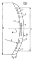
- an intracorneal diffractive lens whose central axis is designated A has an outside diameter D which may be between 5 and 9 mm, and an average curvature defined by a radius R may be between 7 and 9 mm.
- This lens has a convex outer surface S1 and a concave inner surface S2, its thickness E measured between the two surfaces S1 and S2 may be between 0.05 mm and 0.5 mm.
- the useful area of the lens is a circle whose diameter d may be between 3 and 7 mm, depending on the outer diameter D of this lens.
- This useful zone comprises a succession of "solid" rings 2 of optically active material, of increasing diameters, all centered on the axis A, which are separated from each other by "empty" intermediate annular zones 3.
- the rings " 2 and the "empty” intermediate zones 3 are of regularly decreasing width, from the central axis A towards the periphery of the lens, the geometry of the "full" rings 2 being in accordance with the principle of the Fresnel zonal lens. .
- the intracoméenne lens further comprises, at its center, a profiled disk 4 made of the same optically active material as the "full" rings 2, and concentrically or coaxially surrounded by these "full” rings 2.
- the central disk 4 can be assimilated to a first ring "full”, of inner radius equal to zero.
- the "empty" intermediate zones 3 are, in fact, filled with an optically inactive or weakly active material, which is in particular a hydrogel whose percentage of water is equal to or greater than 78%. It may be a hydrogel of the acrylate or methacrylate type, acrylamide or metacylamide, polyester, vinyl copomyler, or the like ... This hydrogel is not only present between the “full” rings 2, but it can also completely coat these rings “full” 2, and the central disc 4, extending to the outer surfaces S1 and inner S2. In all cases, this hydrogel forms a "cement" which connects all the rings 2 between them, thus stabilizing the structure of the lens.
- an optically inactive or weakly active material which is in particular a hydrogel whose percentage of water is equal to or greater than 78%. It may be a hydrogel of the acrylate or methacrylate type, acrylamide or metacylamide, polyester, vinyl copomyler, or the like ...
- This hydrogel is not only present between the “
- the “full” rings 2 and the central disc 4 are made of a material having an optical index different from that of the cornea. It may also be a hydrogel, but the percentage of water is less than 78%, and preferably between 50% and 70%.
- the “full” rings have a permeability lower than that of the cornea and cause, with the central disk 4, the diffraction necessary for the desired vision correction.
- the "empty" intermediate annular zones 3, filled with hydrogel, provide the connection between the rings 2 while being permeable to the flow of nutrients and oxygen.
- outer surfaces S1 and inner S2 may be parallel, so without effect on the correction made, or on the contrary be non-parallel and shaped to participate in the visual correction, by an additional refractive effect.
- Such an intracorneal diffractive lens is achievable by molding or overmolding techniques.
- it can be manufactured for a double injection process.
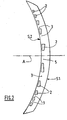
- the figure 2 represents a variant of this intracorneal diffractive lens.
- the central disk is deleted.
- the lens therefore comprises in its center a circular "empty" zone 5, or filled with optically inactive or weakly active but permeable material, such as a suitable hydrogel; the central circular zone 5 is concentrically surrounded by the first "full" annular zone, that is to say by the first ring 2.
- the rings 2 have a lower optical index than the "cement” which connects these rings.
- the "cement” remains, in particular, a hydrogel whose water content is close to 78%, while the rings 2 are made in a hydrogel whose water content is higher than that of said "cement", and typically greater than 85%, or even consisting of water.
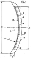
- the figure 3 illustrates a variant of the lens according to the figure 1 , in which the "full" rings 2, as well as the central disc 4, are connected to each other by a thin membrane 6 made of the same optically active material.
- the membrane 6, embedded here in the "empty” intermediate annular zones 3, remains permeable to nutrients due to its very small thickness, and thus allows the "empty" annular zones 3 to play their role.
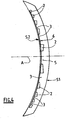
- the figure 4 illustrates a variant of the lens according to the figure 2 , in which the "full" rings 2 are connected to each other others by a thin membrane 6 made of the same optically active material.
- the membrane 6 is here present in the "empty" intermediate annular zones 3, as well as in the central circular zone 5, and as before it does not prevent nutrient transfer.
- figure 5 represents another embodiment, in which the "full" rings 2 of the lens are interconnected by material bridges 7 of radial direction, made in the same optically active material as these rings 2. Because of their fineness, the material bridges 7 form between them and the rings 2 large arc-shaped spaces filled by the inactive but permeable material of the "empty" intermediate zones 3.
- the presence of the membrane 6 or material bridges 7 facilitates the manufacture of the lens, without hindering the vision and without altering the permeability of the "empty" intermediate annular zones 3.
Landscapes
- Health & Medical Sciences (AREA)
- Ophthalmology & Optometry (AREA)
- Vascular Medicine (AREA)
- General Health & Medical Sciences (AREA)
- Transplantation (AREA)
- Engineering & Computer Science (AREA)
- Biomedical Technology (AREA)
- Heart & Thoracic Surgery (AREA)
- Cardiology (AREA)
- Life Sciences & Earth Sciences (AREA)
- Animal Behavior & Ethology (AREA)
- Oral & Maxillofacial Surgery (AREA)
- Public Health (AREA)
- Veterinary Medicine (AREA)
- Prostheses (AREA)
- Eyeglasses (AREA)
- Materials For Medical Uses (AREA)
- Diffracting Gratings Or Hologram Optical Elements (AREA)
- Lenses (AREA)
Description
- La présente invention concerne les lentilles diffractives, en particulier les lentilles intracornéennes, qui sont destinées à être implantées dans la cornée pour la correction de défauts de la vision, aussi désignés comme amétropies. Plus particulièrement, cette invention s'intéresse à une lentille diffractive intracornéenne, utilisable pour la correction chirurgicale de la presbytie.
- Dans le domaine de la correction des amétropies par chirurgie réfractive, on distingue la chirurgie réfractive cornéenne et la chirurgie endoculaire, la chirurgie cornéenne présentant moins de complications.
- La chirurgie réfractive cornéenne est réalisée, à ce jour, par modification de la courbure de la surface antérieure de la cornée.
- Plus particulièrement, la correction de la presbytie par la chirurgie cornéenne se fonde sur la pseudo-accommodation, c'est-à-dire sur la transformation de la cornée en dioptre multifocal par modification de la courbure de la cornée ; dans ce mode de correction réfractif, les performances optiques sont dépendantes du diamètre pupillaire, donc du niveau d'illumination.
- Dans la correction de la presbytie par la chirurgie endoculaire, l'utilisation de lentilles diffractives donne de bons résultats, indépendants du centrage de la lentille et du diamètre pupillaire.
- La transformation de la cornée en une lentille diffractive par sculpture n'est pas possible. Seule l'utilisation d'une lentille diffractive intracornéenne permettrait de bénéficier des propriétés optiques des lentilles diffractives et de l'innocuité de la chirurgie cornéenne.
- Les obstacles actuels à l'utilisation d'implants intracornéens, en particulier de lentilles diffractives intracornéennes, notamment pour le traitement de la presbytie, sont la biocompatibilité de ces implants et surtout leur perméabilité aux flux de nutriments et d'oxygène dans l'épaisseur de la cornée, perméabilité qui est indispensable au maintien de la transparence et de la fonction réfractive de la cornée.
- Les hydrogels à forte teneur en eau sont certes perméables aux nutriments et à l'oxygène, mais ils possèdent un indice de réfraction optique proche de celui de la cornée et sont donc sans efficacité optique pour la réalisation de lentilles diffractives intracornéennes.
- Les documents
EP 0420549 A2 etWO 99/07309 - La présente invention vise à résoudre les problèmes ici présentés, et elle a donc pour but de fournir une lentille diffractive intracornéenne, adaptée au traitement de la presbytie et conçue de manière à permettre une bonne circulation des flux de nutriments et d'oxygène dans l'épaisseur de la cornée, lorsque la lentille est implantée, tout en étant manipulable.
- A cet effet, l'invention a pour objet une lentille diffractive zonale avec inversion de phase, avec alternance de zones annulaires optiquement actives dites « pleines » et de zones annulaires optiquement inactives dites « vides », toutes ces zones annulaires étant concentriques ou coaxiales, cette lentille étant essentiellement caractérisée par le fait que les zones annulaires « vides » sont occupées par un « ciment » optiquement inactif qui relie entre elles les zones annulaires « pleines », pour assurer la stabilité de ces zones annulaires « pleines ».
- Plus particulièrement, la lentille diffractive de l'invention est conçue comme une lentille intracornéenne, dans laquelle le « ciment » des zones annulaires inactives ou « vides » possède une perméabilité aux nutriments et à l'oxygène qui est comparable à celle du tissu cornéen, et un indice optique proche de celui de la cornée.
- Les zones annulaires « pleines » d'une telle lentille peuvent présenter, par rapport aux zones annulaires « vides », une différence d'indice optique telle que l'indice optique des zones annulaires « pleines » soit :
- ou bien plus fort que celui des zones annulaires « vides »;
- ou bien, en variante, plus faible que celui des zones annulaires « vides ».
- Dans une forme de réalisation préférée de la lentille diffractive intracornéenne, objet de l'invention, les zones annulaires « vides » sont remplies par un hydrogel à forte teneur en eau, perméable mais optiquement inactif, constituant le « ciment » reliant les zones annulaires « pleines » pour le maintien de la répartition spatiale concentrique ou coaxiale de ces zones annulaires « pleines », et qui facilite ainsi la manipulation de la lentille. L'hydrogel qui sert ici de « ciment » reliant les zones annulaires « pleines » est en particulier un hydrogel dont le pourcentage en eau est égal ou supérieur à 78 %. Les zones annulaires « pleines », peuvent aussi être réalisées en hydrogel, dont le pourcentage en eau est :
- soit inférieur à 78 %, et de préférence compris entre 50 et 70 % ;
- soit supérieur à 78 %, et de préférence supérieur à 85%, voire être constituées par de l'eau.
- Ainsi, la lentille diffractive intracornéenne, objet de l'invention, se caractérise par une alternance d'anneaux concentriques « pleins », réalisés dans une matière choisie pour son indice optique, et d'anneaux « vides » de préférence remplis d'hydrogel perméable qui assure la cohérence de l'ensemble, les zones « vides » remplies d'hydrogel étant perméables aux nutriments et à l'oxygène, et leur alternance régulière et rapprochée permettant une bonne circulation des flux dans l'épaisseur de la cornée.
- La géométrie d'une telle lentille diffractive zonale, dont les parties optiquement actives sont des zones annulaires « pleines » et concentriques séparées par des interstices, est justifiée de manière théorique, par le principe des lentilles de Fresnel et par la notion d'inversion de phase (Rayleigh Wood phase reversal zone plate).
- En son centre, cette lentille peut comprendre un disque profilé réalisé dans la même matière que les zones annulaires « pleines », et entouré concentriquement ou coaxialement par ces zones annulaires « pleines », le disque central constituant une zone optiquement active à la manière d'un premier anneau de rayon intérieur nul. En variante, la lentille comprend en son centre une zone circulaire « vide », donc optiquement inactive, qui est entourée coaxialement par la première zone annulaire « pleine ».
- Pour des raisons de fabrication, les zones annulaires « pleines » de la lentille, et le cas échéant le disque central, peuvent être reliés par une fine membrane réalisée dans la même matière optiquement active, ladite membrane restant perméable aux nutriments en raison de sa très faible épaisseur.
- Dans une autre forme de réalisation, et toujours pour des raisons de fabrication, les zones annulaires « pleines » de la lentille, et le cas échéant le disque central, sont reliés par des ponts de matière d'orientation générale radiale, réalisés dans la même matière optiquement active, ces ponts de matière traversant les zones annulaires « vides ».
- La membrane ou les ponts de matière facilitent en particulier la manipulation des anneaux, et/ou servent de canaux d'injection lors de la fabrication, sans modifier les propriétés optiques de la lentille ni faire obstacle aux transferts de nutriments.
- La lentille diffractive intracornéenne, objet de l'invention, est réalisable comme une lentille monofocale adaptée pour la correction des amétropies sphériques, ou comme une lentille bifocale, cette dernière version étant adaptée à la correction de la presbytie. La définition précise de la géométrie des faces antérieure et postérieure des zones annulaires « pleines » d'une telle lentille contribue à son adaptation à chaque cas particulier d'application. De plus, dans la mesure où les zones annulaires « pleines » sont non seulement reliées par les parties en hydrogel perméable, mais sont aussi enrobées par des parties réalisées dans le même hydrogel perméable dont les surfaces antérieure et postérieure peuvent être parallèles ou non, ces parties en hydrogel peuvent ou non avoir un effet réfractif additionnel.
- L'invention sera mieux comprise, et d'autres caractéristiques seront mises en évidence, à l'aide de la description qui suit, en référence au dessin schématique annexé représentant, à titre d'exemples, quelques formes d'exécution de cette lentille diffractive intracornéenne :
-
Figure 1 est une vue en coupe diamétrale d'une lentille diffractive intracornéenne conforme à la présente invention, dans un premier mode de réalisation ; -
Figure 2 est une vue en coupe diamétrale d'une lentille diffractive intracoméenne conforme à la présente invention, dans un deuxième mode de réalisation ; -
Figure 3 est une vue similaire à lafigure 1 , illustrant une variante de la lentille selon le premier mode de réalisation ; -
Figure 4 est une vue similaire à lafigure 2 , illustrant une variante de la lentille selon le deuxième mode de réalisation ; -
Figure 5 est une vue de face d'une lentille diffractive intra cornéenne selon un dernier mode de réalisation de l'invention. - En se référant à la
figure 1 , une lentille diffractive intracornéenne dont l'axe central est désigné par A possède un diamètre extérieur D pouvant être compris entre 5 et 9 mm, et une courbure moyenne définie par un rayon R pouvant être compris entre 7 et 9 mm. Cette lentille présente une surface extérieure convexe S1 et une surface intérieure concave S2, son épaisseur E mesurée entre les deux surfaces S1 et S2 pouvant être comprise entre 0,05 mm et 0,5 mm. - La zone utile de la lentille, centrée sur l'axe A, est un cercle dont le diamètre d peut être compris entre 3 et 7 mm, selon le diamètre extérieur D de cette lentille. Cette zone utile comprend une succession d'anneaux « pleins » 2 en matière optiquement active, de diamètres croissants, tous centrés sur l'axe A, qui sont séparés les uns des autres par des zones annulaires intermédiaires « vides » 3. Les anneaux « pleins » 2 et les zones intermédiaires « vides » 3 sont de largeur régulièrement décroissante, depuis l'axe central A en direction de la périphérie de la lentille, la géométrie des anneaux « pleins » 2 étant conforme au principe de la lentille zonale de Fresnel. Dans le mode de réalisation de la
figure 1 , la lentille intracoméenne comprend encore, en son centre, un disque 4 profilé réalisé dans la même matière optiquement active que les anneaux « pleins » 2, et entouré concentriquement ou coaxialement par ces anneaux « pleins » 2. Le disque central 4 peut être assimilé à un premier anneau « plein », de rayon intérieur égal à zéro. - Les zones intermédiaires « vides » 3 sont, en réalité, remplies d'une matière optiquement inactive ou faiblement active, qui est notamment un hydrogel dont le pourcentage en eau est égal ou supérieur à 78 %. Il peut s'agir d'un hydrogel de type acrylate ou métacrylate, acrylamide ou métacylamide, polyester, vinyle copomylère, ou analogue... Cet hydrogel est non seulement présent entre les anneaux « pleins » 2, mais il peut aussi enrober entièrement ces anneaux « pleins » 2, ainsi que le disque central 4, en s'étendant jusqu'aux surfaces extérieure S1 et intérieure S2. Dans tous les cas, cet hydrogel forme un « ciment » qui relie tous les anneaux 2 entre eux, stabilisant ainsi la structure de la lentille.
- Les anneaux « pleins » 2 et le disque central 4 sont réalisés dans une matière possédant un indice optique différent de celui de la cornée. Il peut ici s'agir également d'un hydrogel, mais dont le pourcentage en eau est inférieur à 78 %, et de préférence compris entre 50 % et 70%.
- Les anneaux « pleins » 2, dont le nombre peut être compris entre cinq et trente (le dessin représentant de façon simplifiée un très faible nombre d'anneaux), sont de perméabilité inférieure à celle de la cornée et provoquent, avec le disque central 4, la diffraction nécessaire à la correction de vision souhaitée.
- Les zones annulaires intermédiaires « vides » 3, remplies d'hydrogel, réalisent la liaison entre les anneaux 2 tout en étant perméables aux flux de nutriments et à l'oxygène.
- Les surfaces extérieure S1 et intérieure S2 peuvent être parallèles, donc sans effet sur la correction réalisée, ou au contraire être non parallèles et conformées de manière à participer à la correction visuelle, par un effet réfractif additionnel.
- Une telle lentille diffractive intracornéenne, associant deux matières, est réalisable par des techniques de moulage ou de surmoulage. En particulier, elle peut être fabriquée pour un procédé de double injection.
- La
figure 2 , sur laquelle les éléments correspondant à ceux précédemment décrits sont désignés par les mêmes références (lettres ou chiffres), représente une variante de cette lentille diffractive intracornéenne. Dans cette variante, le disque central est supprimé. La lentille comprend donc en son centre une zone circulaire « vide » 5, ou remplie de matière optiquement inactive ou faiblement active mais perméable, telle qu'un hydrogel adapté ; la zone circulaire centrale 5 est entourée concentriquement par la première zone annulaire « pleine », c'est-à-dire par le premier anneau 2. - Dans une variante, non illustrée directement au dessin, de cette lentille diffractive intracornéenne, les anneaux 2 possèdent un indice optique plus faible que celui du « ciment » qui relie ces anneaux. Dans ce cas le « ciment » reste, en particulier, un hydrogel dont la teneur en eau est proche de 78 %, tandis que les anneaux 2 sont réalisés dans un hydrogel dont la teneur en eau est plus élevée que celle dudit « ciment », et typiquement supérieure à 85 %, voire constitués par de l'eau.
- La
figure 3 illustre une variante de la lentille selon lafigure 1 , dans laquelle les anneaux « pleins » 2, ainsi que le disque central 4, sont reliés les uns aux autres par une fine membrane 6 réalisée dans la même matière optiquement active. La membrane 6, noyée ici dans les zones annulaires intermédiaires « vides » 3, reste perméable aux nutriments en raison de sa très faible épaisseur, et elle permet ainsi aux zones annulaires « vides » 3 de jouer encore leur rôle. - De manière analogue, la
figure 4 illustre une variante de la lentille selon lafigure 2 , dans la quelle les anneaux « pleins » 2 sont reliés les uns aux autres par une fine membrane 6 réalisée dans la même matière optiquement active. En l'absence de disque central, la membrane 6 est ici présente dans les zones annulaires intermédiaires « vides » 3, ainsi que dans la zone circulaire centrale 5, et comme précédemment elle ne fait pas obstacle aux transferts de nutriments. - Enfin, la
figure 5 représente une autre forme de réalisation, dans laquelle les anneaux « pleins » 2 de la lentille sont reliés entre eux par des ponts de matière 7 de direction radiale, réalisés dans la même matière optiquement active que ces anneaux 2. En raison de leur finesse, les ponts de matière 7 ménagent entre eux et les anneaux 2 de larges espaces en forme arcs de cercle remplis par la matière inactive mais perméable des zones intermédiaires « vides » 3. - Comme on le comprend, la présence de la membrane 6 ou des ponts de matière 7 facilite la fabrication de la lentille, sans gêner la vision et sans altérer la perméabilité des zones annulaires intermédiaires « vides » 3.
- On ne s'éloignerait pas du cadre de l'invention, telle que définie dans les revendications annexées, quels que soient notamment :
- les dimensions de la lentille ;
- la nature de ses matières constitutives ;
- le nombre de ses anneaux pleins ;
- la nature du défaut de la vision corrigé par cette lentille.
Claims (14)
- Lentille diffractive zonale avec inversion de phase, avec alternance de zones annulaires optiquement actives dites « pleines » (2) et de zones annulaires optiquement inactives dites « vides » (3), toutes ces zones annulaires étant concentriques ou coaxiales, caractérisée en ce que les zones annulaires « vides » (3) sont occupées par un « ciment » optiquement inactif qui relie entre elles les zones annulaires « pleines » (2), pour assurer la stabilité de ces zones annulaires « pleines » (2).
- Lentille diffractive selon la revendication 1, conçue comme une lentille intracornéenne, caractérisée en ce que le « ciment » des zones annulaires inactives ou « vides » (3) possède une perméabilité aux nutriments et à l'oxygène qui est comparable à celle du tissu cornéen, et un indice optique proche de celui de la cornée.
- Lentille difractive intracoméenne selon la revendication 2, caractérisée en ce que les zones annulaires « pleines » (2) présentent, par rapport aux zones annulaires vides (3), une différence d'indice optique telle que l'indice optique des zones annulaires pleines (2) soit plus fort que celui des zones annulaires vides (3).
- Lentille difractive intracoméenne selon la revendication 2, caractérisée en ce que les zones annulaires « pleines » (2) présentent, par rapport aux zones annulaires vides (3), une différence d'indice optique telle que l'indice optique des zones annulaires pleines (2) soit plus faible que celui des zones annulaires vides (3).
- Lentille diffractive intracornéenne selon la revendication 3 ou 4, caractérisée en ce que les zones annulaires « vides » (3) sont remplies par un hydrogel à forte teneur en eau, perméable mais optiquement inactif, constituant le « ciment » reliant entre elles les zones annulaires « pleines » (2).
- Lentille diffractive intracoméenne selon la revendication 5, caractérisée en ce que l'hydrogel qui sert de « ciment » reliant les zones annulaires
« pleines » (2) est un hydrogel dont le pourcentage en eau est égal ou supérieur à 78 %. - Lentille diffractive intracoméenne selon la revendication 6, caractérisée en ce que les zones annulaires « pleines » (2) sont également en hydrogel, dont le pourcentage en eau est inférieur à 78 %, et de préférence compris entre 50 et 70 %.
- Lentille diffractive intracornéenne selon la revendication 6, caractérisée en ce que les zones annulaires « pleines » (2) sont également en hydrogel, dont le pourcentage en eau est supérieur à 78 %, et de préférence supérieur à 85 %, voire constituées d'eau.
- Lentille diffractive intracoméenne selon l'une des revendications 2 à 8, caractérisée en ce que les zones annulaires « pleines » (2) sont non seulement reliées par les parties en hydrogel perméable, mais sont aussi enrobées par des parties réalisées dans le même hydrogel.
- Lentille diffractive intracoméenne selon l'une des revendications 1 à 9, caractérisée en ce qu'elle comprend en son centre un disque (4) profilé réalisé dans la même matière active que les zones annulaires « pleines » (2), et entouré concentriquement ou coaxialement par ces zones annulaires « pleines » (2), le disque central (4) constituant une zone optiquement active à la manière d'un premier anneau de rayon intérieur nul.
- Lentille diffractive intracoméenne selon l'une des revendications 1 à 9, caractérisé en ce qu'elle comprend en son centre une zone circulaire « vide » (5), donc optiquement inactive, qui est entourée concentriquement par la première zone annulaire « pleine » (2).
- Lentille diffractive intracornéenne selon la revendication 10 ou 11, caractérisée en ce que les zones annulaires « pleines » (2), et le cas échéant le disque central (4), sont reliés par une fine membrane (6) réalisée dans la même matière optiquement active, ladite membrane (6) restant perméable aux nutriments en raison de sa très faible épaisseur.
- Lentille diffractive intracoméenne selon la revendication 10 ou 11, caractérisée en ce que les zones annulaires « pleines » (2), et le cas échéant le disque central (4), sont reliés par des ponts de matière (7) d'orientation générale radiale, réalisés dans la même matière optiquement active, ces ponts de matière (7) traversant le zones annulaires « vides » (3).
- Lentille diffractive intracoméenne selon l'une des revendications 1 à 13, caractérisée en ce qu'elle est réalisée comme une lentille bifocale adaptée à la correction de la presbytie.
Applications Claiming Priority (2)
| Application Number | Priority Date | Filing Date | Title |
|---|---|---|---|
| FR0704963A FR2918557B1 (fr) | 2007-07-09 | 2007-07-09 | Lentille diffractive intracorneenne. |
| PCT/FR2008/001001 WO2009043985A1 (fr) | 2007-07-09 | 2008-07-09 | Lentille diffractive intracorneenne |
Publications (2)
| Publication Number | Publication Date |
|---|---|
| EP2178461A1 EP2178461A1 (fr) | 2010-04-28 |
| EP2178461B1 true EP2178461B1 (fr) | 2012-04-18 |
Family
ID=39148594
Family Applications (1)
| Application Number | Title | Priority Date | Filing Date |
|---|---|---|---|
| EP08836401A Not-in-force EP2178461B1 (fr) | 2007-07-09 | 2008-07-09 | Lentille diffractive intracorneenne |
Country Status (9)
| Country | Link |
|---|---|
| US (1) | US20110046727A1 (fr) |
| EP (1) | EP2178461B1 (fr) |
| JP (1) | JP2010533017A (fr) |
| CN (1) | CN101808594B (fr) |
| AT (1) | ATE553722T1 (fr) |
| CA (1) | CA2694840A1 (fr) |
| ES (1) | ES2388264T3 (fr) |
| FR (1) | FR2918557B1 (fr) |
| WO (1) | WO2009043985A1 (fr) |
Families Citing this family (9)
| Publication number | Priority date | Publication date | Assignee | Title |
|---|---|---|---|---|
| US9335563B2 (en) | 2012-08-31 | 2016-05-10 | Amo Groningen B.V. | Multi-ring lens, systems and methods for extended depth of focus |
| FR2952298B1 (fr) * | 2009-11-06 | 2012-05-25 | Gilbert Cohen | Lentille diffractive intracorneenne avec inversion de phase |
| US9864114B2 (en) * | 2011-09-28 | 2018-01-09 | Hitachi, Ltd. | Zone plate having annular or spiral shape and Y-shaped branching edge dislocation |
| CA3056707A1 (fr) | 2017-03-17 | 2018-09-20 | Amo Groningen B.V. | Lentilles intraoculaires de diffraction permettant une plage de vision etendue |
| US11523897B2 (en) | 2017-06-23 | 2022-12-13 | Amo Groningen B.V. | Intraocular lenses for presbyopia treatment |
| AU2018292024A1 (en) | 2017-06-28 | 2020-01-02 | Amo Groningen B.V. | Diffractive lenses and related intraocular lenses for presbyopia treatment |
| WO2019002390A1 (fr) | 2017-06-28 | 2019-01-03 | Amo Groningen B.V. | Plage étendue et lentilles intraoculaires associées pour le traitement de la presbytie |
| US11327210B2 (en) | 2017-06-30 | 2022-05-10 | Amo Groningen B.V. | Non-repeating echelettes and related intraocular lenses for presbyopia treatment |
| EP4085292A1 (fr) | 2019-12-30 | 2022-11-09 | AMO Groningen B.V. | Lentilles ayant des profils de diffraction ayant une largeur irrégulière pour le traitement de la vision |
Family Cites Families (12)
| Publication number | Priority date | Publication date | Assignee | Title |
|---|---|---|---|---|
| EP0109753B1 (fr) * | 1982-10-27 | 1988-07-27 | Pilkington Plc | Lentille de contact bifocale comprenant une pluralité de zones concentriques |
| US4799931A (en) * | 1986-05-14 | 1989-01-24 | Lindstrom Richard L | Intracorneal lens |
| US4715858A (en) * | 1986-07-25 | 1987-12-29 | Lindstrom Richard L | Epicorneal lens |
| US4909818A (en) * | 1988-11-16 | 1990-03-20 | Jones William F | System and process for making diffractive contact |
| EP0420549A3 (en) * | 1989-09-25 | 1991-06-12 | Kingston Technologies, Inc. | Corneal lens implant |
| US5760871A (en) * | 1993-01-06 | 1998-06-02 | Holo-Or Ltd. | Diffractive multi-focal lens |
| IL118064A0 (en) * | 1995-05-04 | 1996-08-04 | Johnson & Johnson Vision Prod | Concentric annular ring lens designs for astigmatic presbyopes |
| US5628794A (en) * | 1996-03-08 | 1997-05-13 | Lindstrom; Richard L. | Multifocal corneal implant lens having a hydrogelo coating |
| US20010018612A1 (en) * | 1997-08-07 | 2001-08-30 | Carson Daniel R. | Intracorneal lens |
| BR9811081A (pt) * | 1997-08-07 | 2000-08-15 | Alcon Lab Inc | Lente de difração intracorneal |
| US7645299B2 (en) * | 2001-05-11 | 2010-01-12 | Koziol Jeffrey E | Intracorneal lens system having connected lenses |
| JP5109076B2 (ja) * | 2005-07-15 | 2012-12-26 | 並木精密宝石株式会社 | 屈折率制御型回折光学素子及びその製造方法 |
-
2007
- 2007-07-09 FR FR0704963A patent/FR2918557B1/fr not_active Expired - Fee Related
-
2008
- 2008-07-09 ES ES08836401T patent/ES2388264T3/es active Active
- 2008-07-09 CN CN2008800242696A patent/CN101808594B/zh not_active Expired - Fee Related
- 2008-07-09 US US12/668,217 patent/US20110046727A1/en not_active Abandoned
- 2008-07-09 CA CA2694840A patent/CA2694840A1/fr not_active Abandoned
- 2008-07-09 AT AT08836401T patent/ATE553722T1/de active
- 2008-07-09 JP JP2010515551A patent/JP2010533017A/ja active Pending
- 2008-07-09 EP EP08836401A patent/EP2178461B1/fr not_active Not-in-force
- 2008-07-09 WO PCT/FR2008/001001 patent/WO2009043985A1/fr active Application Filing
Also Published As
| Publication number | Publication date |
|---|---|
| CN101808594A (zh) | 2010-08-18 |
| EP2178461A1 (fr) | 2010-04-28 |
| US20110046727A1 (en) | 2011-02-24 |
| ATE553722T1 (de) | 2012-05-15 |
| CA2694840A1 (fr) | 2009-04-09 |
| WO2009043985A1 (fr) | 2009-04-09 |
| JP2010533017A (ja) | 2010-10-21 |
| FR2918557A1 (fr) | 2009-01-16 |
| FR2918557B1 (fr) | 2009-10-02 |
| ES2388264T3 (es) | 2012-10-11 |
| CN101808594B (zh) | 2013-08-14 |
Similar Documents
| Publication | Publication Date | Title |
|---|---|---|
| EP2178461B1 (fr) | Lentille diffractive intracorneenne | |
| EP1093775B1 (fr) | Implant intraoculaire | |
| CA2390888C (fr) | Implant intraoculaire precristallinien | |
| CA2379287C (fr) | Implant formant lentille intraoculaire multifocale | |
| FR2832517A1 (fr) | Lentille de contact pour la correction de myopie et/ou de l'astigmatisme | |
| FR2746000A1 (fr) | Implant intraoculaire souple et ensemble de tels implants | |
| FR2959928A1 (fr) | Systeme de retention d'un organe d'ancrage sur une piece implantable | |
| EP1063946A1 (fr) | Lentille intraoculaire monobloc souple | |
| EP2496179A1 (fr) | Lentille intracorneenne diffractive avec inversion de phase | |
| EP1677707A1 (fr) | Systeme de grandissement d'image retinienne | |
| BE1027321B1 (fr) | Implant phaque de chambre postérieure | |
| EP3415118B1 (fr) | Implant optique intraoculaire comportant une surface de transition | |
| FR2797177A1 (fr) | Implant intraoculaire precristallinien | |
| FR2952297A1 (fr) | Lentille diffractive intracorneenne | |
| BE1027570B1 (fr) | Lentille intraoculaire avec profondeur de champ étendue | |
| EP1176928B1 (fr) | Implant de chambre posterieure aphake chez le myope fort | |
| FR2889601A1 (fr) | Lentille multifocale pour la correction de la presbytie | |
| FR3072872A1 (fr) | Implant optique intraoculaire multifocal | |
| FR3054432A1 (fr) | Lentille intraoculaire a centrage ajustable | |
| FR2835177A1 (fr) | Lentille intraoculaire refractive de chambre posterieure | |
| FR3067591A1 (fr) | Implant intraoculaire pour le traitement de la cataracte chez l'homme et l'animal |
Legal Events
| Date | Code | Title | Description |
|---|---|---|---|
| PUAI | Public reference made under article 153(3) epc to a published international application that has entered the european phase |
Free format text: ORIGINAL CODE: 0009012 |
|
| 17P | Request for examination filed |
Effective date: 20100208 |
|
| AK | Designated contracting states |
Kind code of ref document: A1 Designated state(s): AT BE BG CH CY CZ DE DK EE ES FI FR GB GR HR HU IE IS IT LI LT LU LV MC MT NL NO PL PT RO SE SI SK TR |
|
| AX | Request for extension of the european patent |
Extension state: AL BA MK RS |
|
| DAX | Request for extension of the european patent (deleted) | ||
| GRAP | Despatch of communication of intention to grant a patent |
Free format text: ORIGINAL CODE: EPIDOSNIGR1 |
|
| GRAS | Grant fee paid |
Free format text: ORIGINAL CODE: EPIDOSNIGR3 |
|
| GRAA | (expected) grant |
Free format text: ORIGINAL CODE: 0009210 |
|
| AK | Designated contracting states |
Kind code of ref document: B1 Designated state(s): AT BE BG CH CY CZ DE DK EE ES FI FR GB GR HR HU IE IS IT LI LT LU LV MC MT NL NO PL PT RO SE SI SK TR |
|
| REG | Reference to a national code |
Ref country code: GB Ref legal event code: FG4D Free format text: NOT ENGLISH |
|
| REG | Reference to a national code |
Ref country code: CH Ref legal event code: EP |
|
| REG | Reference to a national code |
Ref country code: IE Ref legal event code: FG4D Free format text: LANGUAGE OF EP DOCUMENT: FRENCH |
|
| REG | Reference to a national code |
Ref country code: AT Ref legal event code: REF Ref document number: 553722 Country of ref document: AT Kind code of ref document: T Effective date: 20120515 |
|
| REG | Reference to a national code |
Ref country code: DE Ref legal event code: R096 Ref document number: 602008015037 Country of ref document: DE Effective date: 20120614 |
|
| REG | Reference to a national code |
Ref country code: NL Ref legal event code: VDEP Effective date: 20120418 |
|
| REG | Reference to a national code |
Ref country code: AT Ref legal event code: MK05 Ref document number: 553722 Country of ref document: AT Kind code of ref document: T Effective date: 20120418 |
|
| LTIE | Lt: invalidation of european patent or patent extension |
Effective date: 20120418 |
|
| REG | Reference to a national code |
Ref country code: ES Ref legal event code: FG2A Ref document number: 2388264 Country of ref document: ES Kind code of ref document: T3 Effective date: 20121011 |
|
| PG25 | Lapsed in a contracting state [announced via postgrant information from national office to epo] |
Ref country code: SE Free format text: LAPSE BECAUSE OF FAILURE TO SUBMIT A TRANSLATION OF THE DESCRIPTION OR TO PAY THE FEE WITHIN THE PRESCRIBED TIME-LIMIT Effective date: 20120418 Ref country code: NO Free format text: LAPSE BECAUSE OF FAILURE TO SUBMIT A TRANSLATION OF THE DESCRIPTION OR TO PAY THE FEE WITHIN THE PRESCRIBED TIME-LIMIT Effective date: 20120718 Ref country code: CY Free format text: LAPSE BECAUSE OF FAILURE TO SUBMIT A TRANSLATION OF THE DESCRIPTION OR TO PAY THE FEE WITHIN THE PRESCRIBED TIME-LIMIT Effective date: 20120418 Ref country code: FI Free format text: LAPSE BECAUSE OF FAILURE TO SUBMIT A TRANSLATION OF THE DESCRIPTION OR TO PAY THE FEE WITHIN THE PRESCRIBED TIME-LIMIT Effective date: 20120418 Ref country code: PL Free format text: LAPSE BECAUSE OF FAILURE TO SUBMIT A TRANSLATION OF THE DESCRIPTION OR TO PAY THE FEE WITHIN THE PRESCRIBED TIME-LIMIT Effective date: 20120418 Ref country code: LT Free format text: LAPSE BECAUSE OF FAILURE TO SUBMIT A TRANSLATION OF THE DESCRIPTION OR TO PAY THE FEE WITHIN THE PRESCRIBED TIME-LIMIT Effective date: 20120418 Ref country code: IS Free format text: LAPSE BECAUSE OF FAILURE TO SUBMIT A TRANSLATION OF THE DESCRIPTION OR TO PAY THE FEE WITHIN THE PRESCRIBED TIME-LIMIT Effective date: 20120818 |
|
| PG25 | Lapsed in a contracting state [announced via postgrant information from national office to epo] |
Ref country code: HR Free format text: LAPSE BECAUSE OF FAILURE TO SUBMIT A TRANSLATION OF THE DESCRIPTION OR TO PAY THE FEE WITHIN THE PRESCRIBED TIME-LIMIT Effective date: 20120418 Ref country code: PT Free format text: LAPSE BECAUSE OF FAILURE TO SUBMIT A TRANSLATION OF THE DESCRIPTION OR TO PAY THE FEE WITHIN THE PRESCRIBED TIME-LIMIT Effective date: 20120820 Ref country code: GR Free format text: LAPSE BECAUSE OF FAILURE TO SUBMIT A TRANSLATION OF THE DESCRIPTION OR TO PAY THE FEE WITHIN THE PRESCRIBED TIME-LIMIT Effective date: 20120719 Ref country code: SI Free format text: LAPSE BECAUSE OF FAILURE TO SUBMIT A TRANSLATION OF THE DESCRIPTION OR TO PAY THE FEE WITHIN THE PRESCRIBED TIME-LIMIT Effective date: 20120418 Ref country code: LV Free format text: LAPSE BECAUSE OF FAILURE TO SUBMIT A TRANSLATION OF THE DESCRIPTION OR TO PAY THE FEE WITHIN THE PRESCRIBED TIME-LIMIT Effective date: 20120418 |
|
| PG25 | Lapsed in a contracting state [announced via postgrant information from national office to epo] |
Ref country code: SK Free format text: LAPSE BECAUSE OF FAILURE TO SUBMIT A TRANSLATION OF THE DESCRIPTION OR TO PAY THE FEE WITHIN THE PRESCRIBED TIME-LIMIT Effective date: 20120418 Ref country code: RO Free format text: LAPSE BECAUSE OF FAILURE TO SUBMIT A TRANSLATION OF THE DESCRIPTION OR TO PAY THE FEE WITHIN THE PRESCRIBED TIME-LIMIT Effective date: 20120418 Ref country code: AT Free format text: LAPSE BECAUSE OF FAILURE TO SUBMIT A TRANSLATION OF THE DESCRIPTION OR TO PAY THE FEE WITHIN THE PRESCRIBED TIME-LIMIT Effective date: 20120418 Ref country code: NL Free format text: LAPSE BECAUSE OF FAILURE TO SUBMIT A TRANSLATION OF THE DESCRIPTION OR TO PAY THE FEE WITHIN THE PRESCRIBED TIME-LIMIT Effective date: 20120418 Ref country code: DK Free format text: LAPSE BECAUSE OF FAILURE TO SUBMIT A TRANSLATION OF THE DESCRIPTION OR TO PAY THE FEE WITHIN THE PRESCRIBED TIME-LIMIT Effective date: 20120418 Ref country code: EE Free format text: LAPSE BECAUSE OF FAILURE TO SUBMIT A TRANSLATION OF THE DESCRIPTION OR TO PAY THE FEE WITHIN THE PRESCRIBED TIME-LIMIT Effective date: 20120418 Ref country code: CZ Free format text: LAPSE BECAUSE OF FAILURE TO SUBMIT A TRANSLATION OF THE DESCRIPTION OR TO PAY THE FEE WITHIN THE PRESCRIBED TIME-LIMIT Effective date: 20120418 |
|
| PLBE | No opposition filed within time limit |
Free format text: ORIGINAL CODE: 0009261 |
|
| STAA | Information on the status of an ep patent application or granted ep patent |
Free format text: STATUS: NO OPPOSITION FILED WITHIN TIME LIMIT |
|
| PG25 | Lapsed in a contracting state [announced via postgrant information from national office to epo] |
Ref country code: MC Free format text: LAPSE BECAUSE OF NON-PAYMENT OF DUE FEES Effective date: 20120731 |
|
| 26N | No opposition filed |
Effective date: 20130121 |
|
| REG | Reference to a national code |
Ref country code: IE Ref legal event code: MM4A |
|
| REG | Reference to a national code |
Ref country code: DE Ref legal event code: R097 Ref document number: 602008015037 Country of ref document: DE Effective date: 20130121 |
|
| PG25 | Lapsed in a contracting state [announced via postgrant information from national office to epo] |
Ref country code: MT Free format text: LAPSE BECAUSE OF FAILURE TO SUBMIT A TRANSLATION OF THE DESCRIPTION OR TO PAY THE FEE WITHIN THE PRESCRIBED TIME-LIMIT Effective date: 20120418 Ref country code: IE Free format text: LAPSE BECAUSE OF NON-PAYMENT OF DUE FEES Effective date: 20120709 Ref country code: BG Free format text: LAPSE BECAUSE OF FAILURE TO SUBMIT A TRANSLATION OF THE DESCRIPTION OR TO PAY THE FEE WITHIN THE PRESCRIBED TIME-LIMIT Effective date: 20120718 |
|
| PGFP | Annual fee paid to national office [announced via postgrant information from national office to epo] |
Ref country code: CH Payment date: 20130614 Year of fee payment: 6 Ref country code: GB Payment date: 20130528 Year of fee payment: 6 |
|
| PGFP | Annual fee paid to national office [announced via postgrant information from national office to epo] |
Ref country code: FR Payment date: 20130626 Year of fee payment: 6 |
|
| PGFP | Annual fee paid to national office [announced via postgrant information from national office to epo] |
Ref country code: ES Payment date: 20130716 Year of fee payment: 6 Ref country code: BE Payment date: 20130731 Year of fee payment: 6 Ref country code: DE Payment date: 20130528 Year of fee payment: 6 |
|
| PGFP | Annual fee paid to national office [announced via postgrant information from national office to epo] |
Ref country code: IT Payment date: 20130710 Year of fee payment: 6 |
|
| PG25 | Lapsed in a contracting state [announced via postgrant information from national office to epo] |
Ref country code: TR Free format text: LAPSE BECAUSE OF FAILURE TO SUBMIT A TRANSLATION OF THE DESCRIPTION OR TO PAY THE FEE WITHIN THE PRESCRIBED TIME-LIMIT Effective date: 20120418 |
|
| PG25 | Lapsed in a contracting state [announced via postgrant information from national office to epo] |
Ref country code: LU Free format text: LAPSE BECAUSE OF NON-PAYMENT OF DUE FEES Effective date: 20120709 |
|
| PG25 | Lapsed in a contracting state [announced via postgrant information from national office to epo] |
Ref country code: HU Free format text: LAPSE BECAUSE OF FAILURE TO SUBMIT A TRANSLATION OF THE DESCRIPTION OR TO PAY THE FEE WITHIN THE PRESCRIBED TIME-LIMIT Effective date: 20080709 |
|
| REG | Reference to a national code |
Ref country code: DE Ref legal event code: R119 Ref document number: 602008015037 Country of ref document: DE |
|
| REG | Reference to a national code |
Ref country code: CH Ref legal event code: PL |
|
| GBPC | Gb: european patent ceased through non-payment of renewal fee |
Effective date: 20140709 |
|
| REG | Reference to a national code |
Ref country code: FR Ref legal event code: ST Effective date: 20150331 |
|
| PG25 | Lapsed in a contracting state [announced via postgrant information from national office to epo] |
Ref country code: CH Free format text: LAPSE BECAUSE OF NON-PAYMENT OF DUE FEES Effective date: 20140731 Ref country code: LI Free format text: LAPSE BECAUSE OF NON-PAYMENT OF DUE FEES Effective date: 20140731 Ref country code: IT Free format text: LAPSE BECAUSE OF NON-PAYMENT OF DUE FEES Effective date: 20140709 Ref country code: DE Free format text: LAPSE BECAUSE OF NON-PAYMENT OF DUE FEES Effective date: 20150203 |
|
| REG | Reference to a national code |
Ref country code: DE Ref legal event code: R119 Ref document number: 602008015037 Country of ref document: DE Effective date: 20150203 |
|
| PG25 | Lapsed in a contracting state [announced via postgrant information from national office to epo] |
Ref country code: FR Free format text: LAPSE BECAUSE OF NON-PAYMENT OF DUE FEES Effective date: 20140731 Ref country code: GB Free format text: LAPSE BECAUSE OF NON-PAYMENT OF DUE FEES Effective date: 20140709 |
|
| REG | Reference to a national code |
Ref country code: ES Ref legal event code: FD2A Effective date: 20151002 |
|
| PG25 | Lapsed in a contracting state [announced via postgrant information from national office to epo] |
Ref country code: ES Free format text: LAPSE BECAUSE OF NON-PAYMENT OF DUE FEES Effective date: 20140710 |
|
| PG25 | Lapsed in a contracting state [announced via postgrant information from national office to epo] |
Ref country code: BE Free format text: LAPSE BECAUSE OF NON-PAYMENT OF DUE FEES Effective date: 20140731 |