EP2177815A2 - Light strip system with shielding element at the joint between two adjacent rails - Google Patents
Light strip system with shielding element at the joint between two adjacent rails Download PDFInfo
- Publication number
- EP2177815A2 EP2177815A2 EP09173526A EP09173526A EP2177815A2 EP 2177815 A2 EP2177815 A2 EP 2177815A2 EP 09173526 A EP09173526 A EP 09173526A EP 09173526 A EP09173526 A EP 09173526A EP 2177815 A2 EP2177815 A2 EP 2177815A2
- Authority
- EP
- European Patent Office
- Prior art keywords
- rails
- shielding element
- shaped
- side wall
- state
- Prior art date
- Legal status (The legal status is an assumption and is not a legal conclusion. Google has not performed a legal analysis and makes no representation as to the accuracy of the status listed.)
- Granted
Links
- 239000004033 plastic Substances 0.000 claims description 9
- 229920003023 plastic Polymers 0.000 claims description 9
- 239000011324 bead Substances 0.000 claims description 5
- 230000007704 transition Effects 0.000 claims description 4
- 239000004952 Polyamide Substances 0.000 claims description 3
- 239000004743 Polypropylene Substances 0.000 claims description 3
- 229920002647 polyamide Polymers 0.000 claims description 3
- 229920000515 polycarbonate Polymers 0.000 claims description 3
- 239000004417 polycarbonate Substances 0.000 claims description 3
- -1 polypropylene Polymers 0.000 claims description 3
- 229920001155 polypropylene Polymers 0.000 claims description 3
- 230000002787 reinforcement Effects 0.000 claims description 2
- 230000004308 accommodation Effects 0.000 abstract 1
- 210000001503 joint Anatomy 0.000 description 18
- 210000003414 extremity Anatomy 0.000 description 9
- 230000008901 benefit Effects 0.000 description 6
- 238000004519 manufacturing process Methods 0.000 description 5
- 239000000463 material Substances 0.000 description 5
- 238000010276 construction Methods 0.000 description 3
- 230000007423 decrease Effects 0.000 description 3
- 238000009434 installation Methods 0.000 description 3
- 238000007789 sealing Methods 0.000 description 3
- 230000006978 adaptation Effects 0.000 description 2
- 229910052782 aluminium Inorganic materials 0.000 description 2
- XAGFODPZIPBFFR-UHFFFAOYSA-N aluminium Chemical compound [Al] XAGFODPZIPBFFR-UHFFFAOYSA-N 0.000 description 2
- 238000013459 approach Methods 0.000 description 2
- 238000013461 design Methods 0.000 description 2
- 238000003780 insertion Methods 0.000 description 2
- 230000037431 insertion Effects 0.000 description 2
- 229920001296 polysiloxane Polymers 0.000 description 2
- 238000012805 post-processing Methods 0.000 description 2
- 238000002360 preparation method Methods 0.000 description 2
- 239000000565 sealant Substances 0.000 description 2
- 238000003466 welding Methods 0.000 description 2
- OKTJSMMVPCPJKN-UHFFFAOYSA-N Carbon Chemical compound [C] OKTJSMMVPCPJKN-UHFFFAOYSA-N 0.000 description 1
- RYGMFSIKBFXOCR-UHFFFAOYSA-N Copper Chemical compound [Cu] RYGMFSIKBFXOCR-UHFFFAOYSA-N 0.000 description 1
- 229910000831 Steel Inorganic materials 0.000 description 1
- 208000027418 Wounds and injury Diseases 0.000 description 1
- 230000032683 aging Effects 0.000 description 1
- 230000005540 biological transmission Effects 0.000 description 1
- 229910052799 carbon Inorganic materials 0.000 description 1
- 230000008859 change Effects 0.000 description 1
- 238000010073 coating (rubber) Methods 0.000 description 1
- 239000011248 coating agent Substances 0.000 description 1
- 238000000576 coating method Methods 0.000 description 1
- 239000002131 composite material Substances 0.000 description 1
- 230000003750 conditioning effect Effects 0.000 description 1
- 238000012790 confirmation Methods 0.000 description 1
- 229910052802 copper Inorganic materials 0.000 description 1
- 239000010949 copper Substances 0.000 description 1
- 230000006378 damage Effects 0.000 description 1
- 210000003298 dental enamel Anatomy 0.000 description 1
- 230000001419 dependent effect Effects 0.000 description 1
- 238000011161 development Methods 0.000 description 1
- 230000018109 developmental process Effects 0.000 description 1
- 239000000428 dust Substances 0.000 description 1
- 230000003628 erosive effect Effects 0.000 description 1
- 238000001125 extrusion Methods 0.000 description 1
- 239000006260 foam Substances 0.000 description 1
- 239000011521 glass Substances 0.000 description 1
- 229910002804 graphite Inorganic materials 0.000 description 1
- 239000010439 graphite Substances 0.000 description 1
- 238000005286 illumination Methods 0.000 description 1
- 230000001771 impaired effect Effects 0.000 description 1
- 208000014674 injury Diseases 0.000 description 1
- 238000009413 insulation Methods 0.000 description 1
- 239000004922 lacquer Substances 0.000 description 1
- 239000007788 liquid Substances 0.000 description 1
- 230000007246 mechanism Effects 0.000 description 1
- 229910052751 metal Inorganic materials 0.000 description 1
- 239000002184 metal Substances 0.000 description 1
- 238000000034 method Methods 0.000 description 1
- 230000003287 optical effect Effects 0.000 description 1
- 239000000843 powder Substances 0.000 description 1
- 238000003825 pressing Methods 0.000 description 1
- 230000008569 process Effects 0.000 description 1
- 238000012545 processing Methods 0.000 description 1
- 230000001681 protective effect Effects 0.000 description 1
- 230000009467 reduction Effects 0.000 description 1
- 230000021317 sensory perception Effects 0.000 description 1
- 238000000926 separation method Methods 0.000 description 1
- 238000005476 soldering Methods 0.000 description 1
- 238000001228 spectrum Methods 0.000 description 1
- 230000006641 stabilisation Effects 0.000 description 1
- 238000011105 stabilization Methods 0.000 description 1
- 239000010959 steel Substances 0.000 description 1
- 238000003860 storage Methods 0.000 description 1
- 230000035882 stress Effects 0.000 description 1
- 238000005382 thermal cycling Methods 0.000 description 1
- 210000003813 thumb Anatomy 0.000 description 1
- 238000012549 training Methods 0.000 description 1
Images

Classifications
-
- F—MECHANICAL ENGINEERING; LIGHTING; HEATING; WEAPONS; BLASTING
- F21—LIGHTING
- F21V—FUNCTIONAL FEATURES OR DETAILS OF LIGHTING DEVICES OR SYSTEMS THEREOF; STRUCTURAL COMBINATIONS OF LIGHTING DEVICES WITH OTHER ARTICLES, NOT OTHERWISE PROVIDED FOR
- F21V21/00—Supporting, suspending, or attaching arrangements for lighting devices; Hand grips
- F21V21/005—Supporting, suspending, or attaching arrangements for lighting devices; Hand grips for several lighting devices in an end-to-end arrangement, i.e. light tracks
-
- F—MECHANICAL ENGINEERING; LIGHTING; HEATING; WEAPONS; BLASTING
- F21—LIGHTING
- F21S—NON-PORTABLE LIGHTING DEVICES; SYSTEMS THEREOF; VEHICLE LIGHTING DEVICES SPECIALLY ADAPTED FOR VEHICLE EXTERIORS
- F21S4/00—Lighting devices or systems using a string or strip of light sources
- F21S4/20—Lighting devices or systems using a string or strip of light sources with light sources held by or within elongate supports
-
- F—MECHANICAL ENGINEERING; LIGHTING; HEATING; WEAPONS; BLASTING
- F21—LIGHTING
- F21V—FUNCTIONAL FEATURES OR DETAILS OF LIGHTING DEVICES OR SYSTEMS THEREOF; STRUCTURAL COMBINATIONS OF LIGHTING DEVICES WITH OTHER ARTICLES, NOT OTHERWISE PROVIDED FOR
- F21V15/00—Protecting lighting devices from damage
- F21V15/01—Housings, e.g. material or assembling of housing parts
- F21V15/013—Housings, e.g. material or assembling of housing parts the housing being an extrusion
-
- F—MECHANICAL ENGINEERING; LIGHTING; HEATING; WEAPONS; BLASTING
- F21—LIGHTING
- F21V—FUNCTIONAL FEATURES OR DETAILS OF LIGHTING DEVICES OR SYSTEMS THEREOF; STRUCTURAL COMBINATIONS OF LIGHTING DEVICES WITH OTHER ARTICLES, NOT OTHERWISE PROVIDED FOR
- F21V15/00—Protecting lighting devices from damage
- F21V15/01—Housings, e.g. material or assembling of housing parts
- F21V15/015—Devices for covering joints between adjacent lighting devices; End coverings
-
- F—MECHANICAL ENGINEERING; LIGHTING; HEATING; WEAPONS; BLASTING
- F21—LIGHTING
- F21V—FUNCTIONAL FEATURES OR DETAILS OF LIGHTING DEVICES OR SYSTEMS THEREOF; STRUCTURAL COMBINATIONS OF LIGHTING DEVICES WITH OTHER ARTICLES, NOT OTHERWISE PROVIDED FOR
- F21V21/00—Supporting, suspending, or attaching arrangements for lighting devices; Hand grips
- F21V21/02—Wall, ceiling, or floor bases; Fixing pendants or arms to the bases
- F21V21/025—Elongated bases having a U-shaped cross section
-
- F—MECHANICAL ENGINEERING; LIGHTING; HEATING; WEAPONS; BLASTING
- F21—LIGHTING
- F21V—FUNCTIONAL FEATURES OR DETAILS OF LIGHTING DEVICES OR SYSTEMS THEREOF; STRUCTURAL COMBINATIONS OF LIGHTING DEVICES WITH OTHER ARTICLES, NOT OTHERWISE PROVIDED FOR
- F21V17/00—Fastening of component parts of lighting devices, e.g. shades, globes, refractors, reflectors, filters, screens, grids or protective cages
- F21V17/10—Fastening of component parts of lighting devices, e.g. shades, globes, refractors, reflectors, filters, screens, grids or protective cages characterised by specific fastening means or way of fastening
- F21V17/20—Fastening of component parts of lighting devices, e.g. shades, globes, refractors, reflectors, filters, screens, grids or protective cages characterised by specific fastening means or way of fastening by toggle-action levers
Definitions
- the invention relates to a lighting system with a plurality of U-shaped rails for receiving light sources, which are arranged one behind the other in the longitudinal direction.
- the rails together form an elongate light exit opening, for which a shielding element designed to prevent the light emission in the abutting area of two adjacent rails is provided.
- the air warmed by the lights at the junction through the slot or the joint joints flows through, as can form after a while traces on a light wall or a gray haze, especially when the lamp with high operating temperature strong convection flow leads.
- dust or foreign bodies should remain in the outer space, since in connection with moisture, the insulation resistances on the holder to the lamps can decrease, which over a certain time can lead to erosion of materials in the vicinity of conductive contacts or creepage currents.
- the aforementioned sealing with a sealant but also excrete before or eventually fail completely, as beyond the manufacturing and manufacturing trends or production batches beyond by mounting the joint width can vary.
- the end faces of the adjoining sides of the profiles in the joint area also be offset somehow.
- the area which could still be wetted with a liquid sealing medium may be exceeded, especially since the processing time in conventional silicone pastes can lead to hurry and also a curing time can delay the further work on the light strip system.
- the gap width can continue to vary, so that even a seal with a small gap width in addition to the direct aging and elasticity losses due to temperature fluctuations, thermal and thermal cycling and cracks by the mechanical walking of the Can get profiles.
- the present invention is therefore based on the object to improve the lighting strip system and to provide a suitable shielding, with which the light leakage is suitably prevented at joints between the joints of abutting similar lights of a light strip.
- a light band system is proposed with a plurality of longitudinally successively arranged, U-shaped rails for receiving light sources, the rails together form an elongated light exit opening and is provided to prevent the light output in the joint area of two adjacent rails shielding, characterized characterized in that the shielding element is adapted to be introduced in a first state from the light exit opening forth in the receiving space of the rails and to be clamped in a second state within the rails with these.
- the shielding element is U-shaped, wherein the underside of the U-shape forms a film hinge in the middle, so that the opposite side wall limbs are folded inwards in the first state and in the second state in pressure-locking contact with the rails are.
- the U-shaped shielding element in the region of the corner between the side wall limb and the lower region of the shielding element has a corner reinforcement, strut or a radius whose center lies on the bisector extending through the corner.
- the U-shaped shielding element in the region of the ends of the side wall limbs has a rounding with a radius suitable for a receptacle in the side wall of the rail, which exceeds a part wall thickness of the side wall limbs, so as to provide a particular stability for the reception and To provide delivery of storage or spring forces.
- the U-shaped shielding member has on the outside of the side wall legs extending from the end of the legs to the lower region strut or a linear bead which extends along the middle of the width of the leg and in the second state by the two adjacent rails completed trained impact area.
- a strut extending from the end of the legs to the lower area or a line-shaped bead of the U-shaped shielding element is formed on the inside of the side wall legs.
- the bridge-like interconnected arms form an H-shaped spring element, in which the arms are T-shaped extending from the axis of rotation formed by the film hinge to the inner sides of the side wall legs.
- the U-shaped shielding element for a lighting system is characterized in that it is made of a plastic such as polypropylene, polycarbonate or polyamide.
- the light band is formed by a plurality of U-shaped profile parts, extruded profiles or rails, which are joined together along a line in the longitudinal direction.
- the joint area of the joints or butt joint area of the rails is overlapped by an element which is releasably in abutment with the U-shaped profile parts.
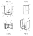
- FIG. 1a a cross-sectional view of a shielding element according to the embodiment of the present invention is shown.
- a U-shaped shielding element 10 initially consists of a lower floor area 2 and two opposite side legs 6.
- a film hinge 4 is formed by a notch or notch-like reduction of the wall thickness.
- a recess 11 is indicated in the bottom region or the underside of the U-shaped shielding element 10 at a symmetrical distance from the film hinge 4.
- the advantage of the greater wall thickness in the corner region lies in the higher rigidity, with the side leg 6 being more firmly connected to the part of the lower bottom region 2, so that forces and moments emanating from the film hinge as a fulcrum can be transmitted better to the sides of the legs.
- the side legs 6 tight against the inside of the rails 88.
- Another advantage of the Eckversteifung is that a constant course of the wall thickness along the side wall leg 6 is possible.
- an enlarged wall thickness is also provided, consisting of a rounding 17 with a radius 19th
- the side wall legs 6 of the shielding element 10 are in the lower region 8 of the side wall legs via two arms 12a and 12b bridge-like connected to each other, wherein in the transition region between the two arms 12a and 12b, a film hinge 14 is formed.
- the arms 12a and 12b and the film hinge 14, mounted on the opposite side wall legs 6 in the lower region 8 of the side wall legs, thereby forming a bridge arrangement.
- the aforementioned arms When installed, the aforementioned arms can be pressed to the bottom or lower region 2 of the U-shaped shielding element 10.
- a compressive force acts along the in Fig. 1a drawn vertical auxiliary line and symmetry axis 16 directed in the direction of the lower portion 2 of the shielding member 10, so that the aforementioned arms are pressed to the underside of the shielding element 10 back and permanently locked in this state.
- the corner regions of the shielding element are pressed to the side, so that the shielding element is clamped in the profile parts of the light strip.
- a certain lateral force is exerted on the side walls of the light leakage preventer, so that they create the side walls of the profile parts.
- the shielding is fixed in the aforementioned position and at the same time it is ensured that all walls are sufficiently tight against the profile body to prevent the desired light emission.
- Fig. 1b shows a side wall or the side wall leg 6 of the U-shaped shielding element 10, that is Fig. 1a 90 degrees clockwise around the dashed in Fig. 1a drawn Symmetrieffenachse was rotated.
- the side wall leg 6 has in the middle of a vertically extending strut 26, a line-shaped bead or ridge. Inside the U-shaped shielding element, the side wall legs 6 may also be stiffened by a grid of struts.
- a butt joint is formed in two contiguous profile parts, which represents an optical gap.
- a certain pressure force conditioning the outer wall of the side wall leg on the inner wall of the extruded profile or rail 88 addition is made possible by the strut 26 an improved cohesive fit, in addition, even the wall stiffness of the side wall leg 6 is increased.
- the gap is filled during assembly and closed.
- the protrusion of the strut in the range of wall thickness or twice the wall thickness of the rail 88 are.
- the geometry of the wall course of the strut, which is engaged with the end faces of the butt joint initially assumed to be straight, a cross-sectional change may have further advantages.
- Fig. 1c shows a plan view of the fallen forward Fig. 1a ,
- the two side wall limbs are each on the right and left outside of the by the in Fig. 1c dashed auxiliary line or axis of rotation through the film hinge 14, wherein the outer end of the respective arms 12a and 12b is connected to the respective sides of the side wall legs.
- a recess is provided centrally to the dashed line auxiliary line, which almost reaches the width of the arms 12 a and 12 b.
- the advantage of the smaller wall width of the arms relative to the wall width of the side wall legs is that the film hinge 14 can be released again from the detent, since under one of the arms 12a or 12b, a lever, for example. Can be created by a screwdriver with a long slot.
- a drawing element missing tension element which may be connected to the film hinge 14, a releasable detent can be realized.
- the bridge-like connected arms have a perpendicular to the auxiliary line centered web or a strut. It is understood that such a configuration is advantageously suitable for mechanical stabilization and increase of the surface rigidity, since the surface resistance or inertia moment increases, as in the case of a T-beam.
- Fig. 1d shows a rotated spatial view of Fig. 1a in which the H-shaped spring element is in a folded position in the preparation position.
- the Eckversteifung or strut 15, which extends along the corner between the bottom and side wall leg 6, the Umkragung or rounding 17 with radius 19 at the ends of the side wall leg, as well as the strut 26, in the present embodiment extends both vertically outside and inside the center along the side wall leg 6 form a mechanically stable form, which is particularly preferably suitable for use in the interior of the rails 88 and an improved system with the guide 83 allowed.
- Fig. 2a corresponds to Fig. 1a showing the preparation position following the insertion of the shielding element 10 in the folded state according to FIG Fig. 2c established.
- Fig. 2b shows the second state of the shielding element 10.
- acoustic confirmation signal On the basis of the above acoustic confirmation signal is certain that the shielding element on the advantageous leadership of the struts 26 on the outside side wall leg 6 is installed correctly and the assembly step has been completed.
- the installer can easily perceive in the absence of click-click or a slightly different sound compared to previous uses of the shielding when the shield is still outside the optimal or pass-correct position, if in rare cases, the strut 26 something wrong or next to the butt joint should lie parallel offset.
- the assembly on the light rail system 88 can be done quickly, since a reassembly of the arrangement after mounting a light exit element by installing a transparent glass or plastic plate or grid reflector at the light exit opening 84 can be avoided, even if in a light path system, the individual light exit elements in turn with each other are connected by a detachable overlap or latching connection.
- the side wall legs 6 fit tightly against the inner surfaces of the rails 88 and the interior 64 kept substantially free remains.
- the aforementioned use of the shielding is thus particularly space-saving, the mounting of the brackets for the lamps can even be done so that the lamp body elongated gas discharge lamps butt-overlapping so can be mounted between two rail profiles.
- the lighting system as an elongated housing profile can be laid, in which the installation of the lamp holders can be offset, or - considering the length of a profile between two joints as rail period length - with freely selectable, different or variable distance between the brackets.
- the aforementioned extended degree of freedom and the laying of lamps in the interior of the rails 88 thus allows an individual adaptation, for example, to the required lighting parameters or brightness, which can thus also be formed lampvariably variable over the length of the lighting system.
- Fig. 2c shows the first state Z1 of the shielding element in which the ends of the sidewall legs are approximated towards the center.
- the space-saving packing-favorably folded shielding element can easily be introduced into the receiving space 64 or the interior of the rail 88 through the light exit opening 84.
- Fig. 2d the position after insertion of the shielding member is shown seated by the strut 26 on the outer wall of the side wall legs 6 in the second state Z2.
- the lighting system is cut free as the rail extending out of the plane of the drawing has been drawn as taken.
- Strut 26 is in contact as a dark black longitudinal line 82 with the end face 86 of the rail. End face 86 is defined by a pattern hatch in FIG Fig. 2d indicated.
- the centrally disposed on the side wall leg 6 strut 26 forms a uniform alignment and guidance of the shielding with the butt joint to the adjacent rail 88.
- the shielding element 10 may likewise consist of any suitable material or suitable material combinations familiar to the person skilled in the art.
- it is a relatively dimensionally stable, elastic, rupturable, durable and opaque material that can be both flexible and rigid.
- suitable materials are plastics such as polypropylene, polycarbonate or polyamide, as well as comparable composite materials, wherein an admixture or a coating of the outside with rubber or foam in the sense of a multi-layer shielding element would be conceivable.
- plastics such as polypropylene, polycarbonate or polyamide, as well as comparable composite materials, wherein an admixture or a coating of the outside with rubber or foam in the sense of a multi-layer shielding element would be conceivable.
- As a manufacturing process extruding with simultaneous exposure to a high frequency spectrum is called.
- the present invention thus provides a simple, elegant, custom-fit possibility to seal the butt joint region of aligned profiled rails in such a way that the light emission is effectively prevented.
- ergonomic, fatigue-free and efficient work on the lighting system is also supported under difficult circumstances at the construction site.
Landscapes
- Engineering & Computer Science (AREA)
- General Engineering & Computer Science (AREA)
- Securing Globes, Refractors, Reflectors Or The Like (AREA)
- Non-Portable Lighting Devices Or Systems Thereof (AREA)
- Investigating Materials By The Use Of Optical Means Adapted For Particular Applications (AREA)
- Length Measuring Devices By Optical Means (AREA)
- Arrangement Of Elements, Cooling, Sealing, Or The Like Of Lighting Devices (AREA)
Abstract
Description
Die Erfindung betrifft ein Lichtbandsystem mit mehreren U-förmigen Schienen zur Aufnahme von Lichtquellen, die in Längsrichtung hintereinander angeordnet werden. Dabei bilden die Schienen gemeinsam eine längliche Lichtaustrittsöffnung, für die ein zur Verhinderung der Lichtabgabe im Stoßbereich zweier benachbarter Schienen ausgebildetes Abschirmelement vorgesehen ist.The invention relates to a lighting system with a plurality of U-shaped rails for receiving light sources, which are arranged one behind the other in the longitudinal direction. In this case, the rails together form an elongate light exit opening, for which a shielding element designed to prevent the light emission in the abutting area of two adjacent rails is provided.
Um über den Einsatz einzelner oder beanstandeter Leuchten hinausgehen zu können, beispielsweise zur gleichmäßigeren Ausleuchtung eines Arbeitsraumes, für eine optisch ansprechende Bauform oder für höhere Leuchtdichten, ist an sich bekannt, die U-förmigen Profilschienen für ein Lichtbandsystem oder eine Lichtlinie anzureihen. Bei Montage als Lichtlinie werden die als Leuchtengehäuse dienenden Strangpressprofile, beispielsweise aus Aluminium oder einem Kunststoff direkt aneinander gestoßen. Dabei zeigt sich jedoch, dass an den Stoßstellen zweier benachbarter Profilkörper Licht durch den Zwischenraum austritt, was unerwünscht ist.In order to be able to go beyond the use of individual or objectionable lights, for example, for more uniform illumination of a working space, for a visually appealing design or for higher luminance, it is known to string the U-shaped rails for a lighting system or a light line. When mounting as a light line serving as a luminaire housing extrusion profiles, such as aluminum or a plastic are pushed directly to each other. It turns out, however, that at the joints of two adjacent profile body light exits through the gap, which is undesirable.
Weiters sollte vermieden werden können, dass die von den Leuchten angewärmte Luft an der Stoßstelle durch den Schlitz bzw. die Stoßstellenfuge hindurchströmt, da sich nach einer gewissen Zeit Spuren an einer hellen Wand oder ein Grauschleier ausbilden können, gerade wenn die Lampe mit hoher Betriebstemperatur zu starker Konvektionsströmung führt. Auch sollen möglichst Staub oder Fremdkörper im Außenraum verbleiben, da im Zusammenhang mit Feuchtigkeit die Isolationswiderstände an der Halterung zu den Lampen abnehmen können, welches über eine gewisse Zeit zu einer Erosion von Materialien in der Nähe von leitenden Kontakten oder zu Kriechströmen führen kann.Furthermore, it should be avoided that the air warmed by the lights at the junction through the slot or the joint joints flows through, as can form after a while traces on a light wall or a gray haze, especially when the lamp with high operating temperature strong convection flow leads. Also, if possible dust or foreign bodies should remain in the outer space, since in connection with moisture, the insulation resistances on the holder to the lamps can decrease, which over a certain time can lead to erosion of materials in the vicinity of conductive contacts or creepage currents.
Nun könnte man versuchen, mit einer lichtundurchlässigen Silikonpaste, einem Kitt oder einer Spachtelmasse derartige Fugen einfach abzudichten. Dabei wäre zunächst der Arbeitsaufwand und die Montagezeit zu berücksichtigen, der bei einem Lichtbandsystem mit vielen Elementen erheblich wäre. Allerdings ist das Aussehen der Dichtungen vom handwerklichen Geschick und der Geduld des Ausführenden abhängig. Weiters können auch Nachbearbeitungsschritte nach Aushärten der Dichtmasse, wie ein Entfernen eines Überhanges hinzukommen, wobei die Oberfläche der Profile beeinträchtigt werden könnte, selbst wenn diese mit einer später abziehbaren Kunststoff schutzfolie herstellerseitig versiegelt sind. Vorgenannter Ansatz mag bei ein paar wenigen Elementen oder als Provisorium in Frage kommen.Now you could try to seal such joints simply with an opaque silicone paste, a putty or a putty. First of all, it would be necessary to take into account the amount of work involved and the assembly time, which would be considerable in the case of a continuous-row lighting system with many elements. However, the appearance of the seals depends on the craftsmanship and patience of the performer. Furthermore, post-processing steps can be added after curing of the sealant, such as removing an overhang, wherein the surface of the profiles impaired could be, even if they are sealed with a later removable plastic protective film manufacturer. The aforementioned approach may be suitable for a few elements or as a temporary solution.
Allerdings kann vorgenanntes Abdichten mit einer Dichtmasse jedoch auch schon vorher ausscheiden oder schließlich ganz misslingen, da über die Herstellungs- und Fertigungstendenzen oder Produktionschargen hinausgehend auch durch Montage die Fugenbreite variieren kann. So können beispielsweise bei Montage der Profile an einer unebenen Decke die Stirnflächen der anstoßenden Seiten der Profile im Fugenbereich auch irgendwie versetzt sein. Weiter kann der Bereich, der mit einem flüssigen Abdichtungsmedium noch benetzt werden könnte, überschritten sein, zumal die Verarbeitungszeit bei herkömmlichen Silikonpasten zu Eile verleiten kann und auch eine Aushärtzeit die Weiterarbeit am Lichtbandsystem verzögern kann. Da sich die Profile aufgrund beim Betrieb der Leuchte einstellenden Temperaturgradienten auch relativ bewegen, kann auch die Spaltbreite weiterhin variieren, so dass selbst eine Abdichtung bei geringer Spaltbreite neben der direkten Alterung und Elastizitätseinbußen durch Temperaturschwankungen, Wärme- und Temperaturwechselbeanspruchungen auch Risse durch das mechanische Walken der Profile bekommen kann.However, the aforementioned sealing with a sealant but also excrete before or eventually fail completely, as beyond the manufacturing and manufacturing trends or production batches beyond by mounting the joint width can vary. For example, when mounting the profiles on an uneven ceiling, the end faces of the adjoining sides of the profiles in the joint area also be offset somehow. Furthermore, the area which could still be wetted with a liquid sealing medium may be exceeded, especially since the processing time in conventional silicone pastes can lead to hurry and also a curing time can delay the further work on the light strip system. Since the profiles also move relatively due to the temperature gradient setting during operation of the luminaire, the gap width can continue to vary, so that even a seal with a small gap width in addition to the direct aging and elasticity losses due to temperature fluctuations, thermal and thermal cycling and cracks by the mechanical walking of the Can get profiles.
Ebenso könnte man noch daran denken, die Profile stoffschlüssig zu verbinden. Zwar mag Vorgenanntes bei Stahl im Bereich einer bestimmten Wanddicke beispielsweise durch Punktverschweißen, bei Kupferblech durch Hart- oder Weichlöten denkbar sein. Allerdings wird ein Verschweißen, gerade bei dünnen Aluminiumprofilen an der Baustelle eher ausgeschlossen sein und sich eher verbieten, wenn die Formhohlkörperprofilschienen behandelt, elektrolytisch oxidiert oder die Oberfläche mit einer Kunststoff-, Lack-, oder Pulver- oder Emailschicht überzogen, glatt oder auf Spiegelglanz veredelt sind. Gleichwohl begegnet Vorgenanntes schließlich den Fertigkeiten des jeweiligen Monteurs und einer eventuell räumlich beengten Arbeitsumgebung am Montageort. Schließlich würden wiederum die betriebsbedingten Temperaturgradienten auch zu mechanischen Spannungen führen. Im Ergebnis können so die Verbindungsnähte brüchig werden oder reißen, wie dies in anderen Größenordnungen von Eisenbahnschienen bekannt ist, und das Verfahren wäre zu wiederholen.Similarly, one could still remember to connect the profiles cohesively. Although the above may be conceivable for steel in the range of a certain wall thickness, for example by spot welding, copper sheet by hard or soft soldering. However, welding, especially with thin aluminum profiles at the construction site, is more likely to be ruled out and is more likely to be prohibited if the molded hollow profile rails are treated, electrolytically oxidized or the surface is coated with a layer of plastic, lacquer or powder or enamel, smooth or mirror-finished are. Nevertheless, the aforementioned finally meets the skills of the respective installer and a possibly cramped working environment at the installation site. Finally, in turn, the operational temperature gradients would also lead to mechanical stresses. As a result, the seams may become brittle or crack, as is known in other sizes of railroad tracks, and the process should be repeated.
Im Ergebnis fehlt es jedenfalls bisher an einer sicheren und eleganten Möglichkeit, die Stoßfuge zwischen benachbarten Schienen bei einem Lichtbandsystem zu schließen.As a result, it has been missing in any case so far a safe and elegant way to close the butt joint between adjacent rails in a lighting system.
Aus der Offenlegungsschrift
Um die einzelnen Teile des Lichtbandsystems zu verbessern, dass dieses auch gegen einen Lichtaustritt an den Stoßfugenbereichen abgedichtet werden kann, ist es erforderlich, dass das geeignete Abschirmelement einfach eingesetzt werden kann und mit einer gewissen Kraft an den Seitenteilen der Profilteile anlegt bzw. anliegt. Dabei sollten also auch die Seitenteile ausgerichtet werden können, dass eine sog. sauber abschließende, geometrisch regelrechte und damit auch optisch ansprechende Fugendichtung geschaffen werden kann, welches wiederum Voraussetzung ist für eine zumindest lichtdichte Trennung des Innenbereiches des Lichtbandsystems vom Außenraum. Darüberhinausgehend wäre eine gewisse Beweglichkeit bzw. Elastizität einer Dichtung in der Profilschiene wünschenswert.In order to improve the individual parts of the lighting strip system that this can be sealed against light leakage at the butt joint areas, it is necessary that the appropriate shielding element can be easily inserted and applies or rests with a certain force on the side parts of the profile parts. In this case, therefore, the side parts should be aligned so that a so-called. Clean final, geometrically veritable and thus visually appealing joint seal can be created, which in turn is a prerequisite for an at least light-tight separation of the inner region of the lighting system from the outside. In addition, a certain mobility or elasticity of a seal in the rail would be desirable.
Der vorliegenden Erfindung liegt deshalb die Aufgabe zu Grunde, das Lichtbandsystem zu verbessern und ein geeignetes Abschirmelement zu schaffen, mit dem der Lichtaustritt an Fugen zwischen den Verbindungsstellen aneinanderstoßender gleichartiger Leuchten eines Lichtbandes geeignet verhindert wird.The present invention is therefore based on the object to improve the lighting strip system and to provide a suitable shielding, with which the light leakage is suitably prevented at joints between the joints of abutting similar lights of a light strip.
Die Aufgabe wird durch ein Lichtbandsystem gemäß Anspruch 1 und durch ein Element zur Verwendung bei einem Lichtbandsystem gemäß dem Anspruch 10 gelöst. Vorteilhafte Weiterbildungen sind Gegenstand der abhängigen Ansprüche.The object is achieved by a lighting system according to claim 1 and by an element for use in a lighting system according to
Demgemäß wird nach einer ersten Ausführungsform ein Lichtbandsystem vorgeschlagen mit mehreren in Längsrichtung hintereinander anzuordnenden, U-förmigen Schienen zur Aufnahme von Lichtquellen, wobei die Schienen gemeinsam eine längliche Lichtaustrittsöffnung bilden und ein zur Verhinderung der Lichtabgabe im Stoßbereich zweier benachbarter Schienen ausgebildetes Abschirmelement vorgesehen ist, dadurch gekennzeichnet, dass das Abschirmelement dazu ausgebildet ist, in einem ersten Zustand von der Lichtaustrittsöffnung her in den Aufnahmeraum der Schienen eingeführt zu werden und in einem zweiten Zustand innerhalb der Schienen mit diesen verklemmt zu sein.Accordingly, according to a first embodiment, a light band system is proposed with a plurality of longitudinally successively arranged, U-shaped rails for receiving light sources, the rails together form an elongated light exit opening and is provided to prevent the light output in the joint area of two adjacent rails shielding, characterized characterized in that the shielding element is adapted to be introduced in a first state from the light exit opening forth in the receiving space of the rails and to be clamped in a second state within the rails with these.
Bevorzugt ist, dass das Abschirmelement U-förmig ist, wobei die Unterseite der U-Form in der Mitte ein Filmscharnier ausbildet, so dass die gegenüberliegenden Seitenwandschenkel in dem ersten Zustand nach innen gefaltet sind und in dem zweiten Zustand in druckschlüssiger Anlage mit den Schienen befindlich sind.It is preferred that the shielding element is U-shaped, wherein the underside of the U-shape forms a film hinge in the middle, so that the opposite side wall limbs are folded inwards in the first state and in the second state in pressure-locking contact with the rails are.
Weiter bevorzugt ist, dass das U-förmige Abschirmelement im Bereich der Ecke zwischen Seitenwandschenkel und unterem Bereich des Abschirmelementes eine Eckversteifung, Strebe oder einen Radius aufweist, dessen Mittelpunkt auf der durch die Ecke verlaufenden Winkelhalbierenden liegt.It is further preferred that the U-shaped shielding element in the region of the corner between the side wall limb and the lower region of the shielding element has a corner reinforcement, strut or a radius whose center lies on the bisector extending through the corner.
Besonders bevorzugt ist, dass das U-förmige Abschirmelement im Bereich der Enden der Seitenwandschenkel eine Rundung mit einem Radius aufweist, passend für eine Aufnahme in der Seitenwand der Schiene, der einen Teil Wanddicke der Seitenwandschenkel übersteigt, um so eine besondere Stabilität für die Aufnahme und Abgabe von Speicher- bzw. Federkräften bereitstellen zu können.It is particularly preferred that the U-shaped shielding element in the region of the ends of the side wall limbs has a rounding with a radius suitable for a receptacle in the side wall of the rail, which exceeds a part wall thickness of the side wall limbs, so as to provide a particular stability for the reception and To provide delivery of storage or spring forces.
Daneben ist bevorzugt, dass das U-förmige Abschirmelement auf der Außenseite der Seitenwandschenkel eine vom Ende der Schenkel zum unteren Bereich verlaufende Strebe oder einen linienförmigen Wulst aufweist, der entlang der Mitte der Breite des Schenkel verläuft und im zweiten Zustand den durch die zwei benachbarten Schienen ausgebildeten Stoßbereiches ausfüllt.In addition, it is preferred that the U-shaped shielding member has on the outside of the side wall legs extending from the end of the legs to the lower region strut or a linear bead which extends along the middle of the width of the leg and in the second state by the two adjacent rails completed trained impact area.
Daneben ist besonders bevorzugt, dass eine vom Ende der Schenkel zum unteren Bereich verlaufende Strebe oder einen linienförmigen Wulst des U-förmigen Abschirmelements auf der Innenseite der Seitenwandschenkel ausgebildet ist.In addition, it is particularly preferred that a strut extending from the end of the legs to the lower area or a line-shaped bead of the U-shaped shielding element is formed on the inside of the side wall legs.
Weiter ist vorgesehen, dass im unteren Bereich der Seitenwandschenkel über zwei Arme brückenartig miteinander verbunden sind, wobei im Übergangsbereich zwischen den beiden nach innen weisenden Armen ein Filmscharnier ausgebildet ist.It is further provided that in the lower region of the side wall legs are connected to each other bridge-like manner via two arms, wherein in the transition region between the two inwardly facing arms, a film hinge is formed.
Besonders bevorzugt ist vorgesehen, dass die brückenartig miteinander verbundenen Arme ein H-förmiges Federelement ausbilden, bei dem die Arme T-förmig ausgehend von der durch das Filmscharnier gebildeten Drehachse zu den Innenseiten der Seitenwandschenkel verlaufend, ausgebildet sind.Particularly preferably it is provided that the bridge-like interconnected arms form an H-shaped spring element, in which the arms are T-shaped extending from the axis of rotation formed by the film hinge to the inner sides of the side wall legs.
Weiter ist noch bevorzugt im zweiten Zustand das Filmscharnier des H-förmigen Federelements mit dem Filmscharnier im unteren Bereich des U-förmigen Abschirmelements in Anlage.Next is still preferred in the second state, the film hinge of the H-shaped spring element with the film hinge in the lower region of the U-shaped shield in abutment.
Schließlich ist ein U-förmiges Abschirmelement für ein Lichtbandsystem mit mehreren in Längsrichtung hintereinander anzuordnenden, U-förmigen Schienen zur Aufnahme von Lichtquellen, wobei die Schienen gemeinsam eine längliche Lichtaustrittsöffnung bilden und ein zur Verhinderung der Lichtabgabe im Stoßbereich zweier benachbarter Schienen ausgebildetes Abschirmelement vorgesehen, dadurch gekennzeichnet, dass das Abschirmelement dazu ausgebildet ist, in einem ersten Zustand von der Lichtaustrittsöffnung her in den Aufnahmeraum der Schienen eingeführt zu werden und in einem zweiten Zustand innerhalb der Schienen mit diesen verklemmt zu sein.Finally, a U-shaped shielding element for a lighting system with a plurality of longitudinally successive to be arranged, U-shaped rails for receiving light sources, the rails together form an elongated light exit opening and provided to prevent the light output in the joint area of two adjacent rails shielding, characterized in in that the shielding element is designed to be introduced into the receiving space of the rails in a first state from the light exit opening and to be clamped in a second state within the rails with the latter.
Schließlich ist das U-förmige Abschirmelement für ein Lichtbandsystem dadurch gekennzeichnet, dass es aus einem Kunststoff wie Polypropylen, Polycarbonat oder Polyamid gefertigt ist.Finally, the U-shaped shielding element for a lighting system is characterized in that it is made of a plastic such as polypropylene, polycarbonate or polyamide.
Bei dem Ausführungsbeispiel der vorliegenden Erfindung wird das Lichtband durch mehrere U-förmige Profilteile, Strangpressprofile oder Schienen gebildet, welche, entlang einer Linie in der Längsrichtung verlaufend, aneinander angefügt werden. Der Fugenbereich der Stoßstellen bzw. Stoßfugenbereich der Schienen wird durch ein Element überlappt, das sich mit den U-förmigen Profilteilen lösbar in Anlage befindet.In the embodiment of the present invention, the light band is formed by a plurality of U-shaped profile parts, extruded profiles or rails, which are joined together along a line in the longitudinal direction. The joint area of the joints or butt joint area of the rails is overlapped by an element which is releasably in abutment with the U-shaped profile parts.
Nachfolgend soll die Erfindung anhand der beiliegenden Zeichnung näher erläutert werden. Es zeigen:
- Fig. 1a
- eine schematische Querschnittansicht eines Abschirmelementes gemäß dem Ausführungsbeispiel der vorliegenden Erfindung für ein Uförmiges Profil;
- Fig. 1b
- eine schematische Ansicht auf einen Seitenwandschenkel des Abschirmelementes zu
Fig. 1a ; - Fig. 1c
- eine schematische Ansicht von oben auf das U-förmige Abschirmelement zur
Fig. 1a mit einer Ausnehmung; - Fig. 1d
- eine räumliche Schrägansicht von
Fig. 1a ; - Fig. 2a
- die Querschnittansicht des Abschirmelementes gemäß
Fig. 1a ; - Fig. 2b
- eine Querschnittansicht des Abschirmelementes, eingeführt in ein längliches Profil in einem zweiten Zustand;
- Fig. 2c
- eine Querschnittsansicht des Abschirmelementes, in einem ersten Zustand; und
- Fig. 2d
- eine räumliche Schrägansicht von
Fig. 2b .
- Fig. 1a
- a schematic cross-sectional view of a shielding element according to the embodiment of the present invention for a U-shaped profile;
- Fig. 1b
- a schematic view of a side wall limb of the shielding to
Fig. 1a ; - Fig. 1c
- a schematic top view of the U-shaped shielding for
Fig. 1a with a recess; - Fig. 1d
- a spatial perspective view of
Fig. 1a ; - Fig. 2a
- the cross-sectional view of the shield according to
Fig. 1a ; - Fig. 2b
- a cross-sectional view of the shielding element, introduced into an elongated profile in a second state;
- Fig. 2c
- a cross-sectional view of the shielding, in a first state; and
- Fig. 2d
- a spatial perspective view of
Fig. 2b ,
In
An der Ecke 13 zwischen dem Seitenwandschenkel 6 und unteren Bereiches des Abschirmelementes 2 ist vergrößerte Wanddicke vorgesehen, im Sinne einer Versteifung oder Eckverstrebung 15.At the
Über eine übliche Rundung bzw. einen Radius hinaus, bei dem dessen Mittelpunkt auf der Winkelhalbierenden des unteren Bereiches 2 und des Seitenwandschenkels 6 liegt (konkaver Radius), derart, dass die Ecke geglättet bzw. gefüllt ist, wurde vorliegend in
Der Vorteil der größeren Wanddicke im Eckbereich liegt in der höheren Steifigkeit, wobei der Seitenschenkel 6 mit dem Teil des unteren Bodenbereiches 2 fester verbunden ist, so dass vom Filmscharnier als Drehpunkt ausgehende Kräfte und Momente besser auf den Seiten Schenkel übertragen werden können. Damit kann der Seitenschenkel 6 eng an der Innenseite der Schienen 88 anliegen. Ein weiterer Vorteil der Eckversteifung besteht darin, dass ein konstanter Verlauf der Wanddicke entlang des Seitenwandschenkels 6 möglich ist.The advantage of the greater wall thickness in the corner region lies in the higher rigidity, with the side leg 6 being more firmly connected to the part of the
Am oberen Ende des Seitenschenkels 6 ist ebenfalls eine vergrößerte Wanddicke vorgesehen, bestehend aus einer Rundung 17 mit einem Radius 19.At the upper end of the side leg 6, an enlarged wall thickness is also provided, consisting of a rounding 17 with a radius 19th
Die Vorteile des gerundeten Endabschlusses mit geometrisch definierter Wanddickenzunahme oder in einer Art gerundeten Falzbördelung sind mehrfach gegeben. Zunächst ist die Kraftübertragung von Spann- und Druck- und Formschlußkräften über eine vergrößerte Endkontaktfläche verbessert. Übrigens ist eine leichte Drehung des Seitenschenkels zu berücksichtigen, geringfügig auch während des Betriebes über eine gewisse Zeit bei Temperaturgang der Profilschiene.The advantages of the rounded end termination with geometrically defined increase in wall thickness or in a kind of rounded seam crimp are given several times. First, the power transmission of clamping and pressure and positive engagement forces is improved over an enlarged Endkontaktfläche. Incidentally, a slight rotation of the side leg is to be considered, slightly even during operation for a certain time at temperature profile of the rail.
Weiter liegt eine bessere Passung und Anpassung des Abschirmelementes 10 in das Profil 88 vor. Schließlich entfällt aufgrund der besseren Handlichkeit und Ergonomie bei der Montage auch eine eventuelle Verletzungsgefahr für den Monteur mangels sonst möglicherweise bei herkömmlichen Lösungsansätzen vorhandenen scharfen Kanten oder einem produktionsbedingten Grat. Übrigens entfällt bei dem vorteilhaft ausgebildeten Ende des Seitenwandschenkels 6 ebenso eine sonst erforderliche Nachbearbeitung für das Ausbilden einer Fase, wobei die damit einhergehende Wanddickenabnahme die Passung und den Sitz des Abschirmelementes 2 in das bzw. in dem Profil 88 in Frage stellen würde.Furthermore, there is a better fit and adaptation of the shielding
Die Seitenwandschenkel 6 des Abschirmelementes 10 sind im unteren Bereich 8 der Seitenwandschenkel über zwei Arme 12a und 12b brückenartig mit einander verbunden, wobei im Übergangsbereich zwischen den beiden Armen 12a und 12 b ein Filmscharnier 14 ausgebildet ist. Die Arme 12a und 12b und das Filmscharnier 14, gelagert an den sich gegenüberliegenden Seitenwandschenkeln 6 im unteren Bereich 8 der Seitenwandschenkel, bilden dabei eine Brückenanordnung.The side wall legs 6 of the shielding
Im eingebauten Zustand können vorgenannte Arme zur Unterseite bzw. zum unteren Bereich 2 des U-förmigen Abschirmelements 10 hingedrückt werden. Dabei wirkt im eingebauten Zustand eine Druckkraft entlang der in
Die von den Innenseiten der Seitenwandschenkel in das Innere des Abschirmelementes 10 hineinragenden Arme sind verhältnismäßig weit unten, im unteren Bereich der Seitenwandschenkel 8 angeordnet, so dass immer noch, auch im montierten Zustand des Abschirmelementes 10, ein genügend großer Freiraum innerhalb der Profilelemente bzw. Schienen 88 verbleibt. Durch Vorgenanntes wird sichergestellt, dass auch in diesem Bereich Leuchtmittel angeordnet werden können.The protruding from the inner sides of the side wall legs in the interior of the
Daraus ergeben sich folgende Vorteile. Zunächst wird bei zwei aneinander liegenden Profilteilen eine Stoßfuge gebildet, die einen optischen Spalt darstellt. Über die mit einer gewissen Andruckkraft erfolgende Anlage der Außenwand des Seitenwandschenkels an der Innenwand des Strangpressprofils oder der Schiene 88 hinaus gehend, wird durch die Strebe 26 eine verbesserte auch stoffschlüssige Passung ermöglicht, wobei zusätzlich noch die Wandsteifigkeit des Seitenwandschenkels 6 erhöht wird.This results in the following advantages. First, a butt joint is formed in two contiguous profile parts, which represents an optical gap. About the taking place with a certain pressure force conditioning the outer wall of the side wall leg on the inner wall of the extruded profile or
Zunächst wird also die Fuge bei der Montage ausgefüllt und geschlossen. Bevorzugt kann das Herausragen der Strebe im Bereich der Wanddicke oder der doppelten Wanddicke der Schiene 88 liegen. Außerhalb der Darstellung kann die Geometrie des Wandverlaufes der Strebe, die mit den Stirnseiten der Stoßfuge in Eingriff steht zunächst als gerade angenommen werden, eine Querschnittsänderung kann weitere Vorteile haben.First, so the gap is filled during assembly and closed. Preferably, the protrusion of the strut in the range of wall thickness or twice the wall thickness of the
Würde man sich in die Ebene des Seitenwandschenkels begeben, also die Seitenwand in der Bildbetrachtungsebene der
Überraschend gelingt es also, durch die Strebe auch die nahezu parallel verlaufenden, also entlang des Lichtbandsystems entlanglaufenden Strahlen, die bei einer einfachen Anlage einer glatten Fläche eventuell doch noch im Spalt ankämen, am Durchtritt durch den Spalt zu verhindern und zwar bereits bei einem kleinen Überstand der Strebe über die Fläche des Seitenwandschenkels 6.Surprisingly, therefore, it is also possible to prevent the passage through the gap by the strut and the rays running parallel along the light band system, which would possibly still arrive in the gap in the case of a simple contact of a smooth surface, even with a small projection the strut on the surface of the side wall leg. 6
Die brückenartig verbundenen Arme weisen einen senkrecht zur Hilfslinie mittig verlaufende Steg bzw. eine Strebe auf. Es versteht sich, dass eine derartige Ausgestaltung vorteilhaft zur mechanischen Stabilisierung und Erhöhung der Flächensteifigkeit geeignet sind, da sich das Flächenwiderstands- bzw. -trägheitsmoment, wie bei einem T-Träger erhöht.The bridge-like connected arms have a perpendicular to the auxiliary line centered web or a strut. It is understood that such a configuration is advantageously suitable for mechanical stabilization and increase of the surface rigidity, since the surface resistance or inertia moment increases, as in the case of a T-beam.
Besonders vorteilhaft kann, über die haptische bzw. tastsensorische Wahrnehmung durch Kraftanlage hinaus, beim Übergang vom ersten in den zweiten Zustand bei Anstoßen des Scharniers 14 an die Unterseite 2 des Abschirmelementes im Bereich des Scharniers 4 ein kurzes perkusives Einrast- oder Klick-Geräusch erzeugt werden.Particularly advantageously, beyond the haptic or tactile sensory perception by force installation, during the transition from the first to the second state when the
Anhand des vorstehenden akustischen Bestätigungs-Signals besteht Gewissheit, dass das Abschirmelement über die vorteilhafte Führung der Streben 26 auf der Außenseite Seitenwandschenkel 6 richtig eingebaut ist und der Montageschritt vollständig erfolgt ist. Daneben kann der Monteur bei Ausbleiben des Rast-Klicks oder bei einem etwas unterschiedlichen Klang gegenüber vorherigen Einsätzen des Abschirmelementes leicht wahrnehmen, wenn das Abschirmelement noch außerhalb der optimalen bzw. passrichtigen Lage ist, falls in seltenen Fällen die Strebe 26 etwas neben der Stoßfuge schief oder parallelversetzt anliegen sollte. Mithin kann die Montage am Lichtbahnsystem 88 zügig von statten gehen, da ein Wiederauseinanderbauen der Anordnung nach Montage eines Lichtaustrittselements durch Einbau einer transparenten Glas- oder Kunststoffplatte bzw. Rasterreflektor an der Lichtaustrittsöffnung 84 vermieden werden kann, gerade wenn bei einem Lichtbahnsystem die einzelnen Lichtaustrittselemente seinerseits miteinander durch eine lösbare Überlappung oder Rastverbindung verbunden sind.On the basis of the above acoustic confirmation signal is certain that the shielding element on the advantageous leadership of the
Besonders vorteilhaft ist dabei, dass nun die Seitenwandschenkel 6 eng an den Innenflächen der Schienen 88 anliegen und der Innenraum 64 im wesentlichen freigehalten bleibt. Vorgenannter Einsatz des Abschirmelementes ist damit besonders platzsparend, wobei die Montage der Halterungen für die Lampen sogar so erfolgen kann, dass die Lampenkörper länglicher Gasentladungslampen Stoßfugen-überlappend also zwischen zwei Schienenprofilen angebracht werden können. Bei vorgenanntem ist also das Lichtbandsystem als langgestrecktes Gehäuseprofil verlegbar, bei dem der Einbau der Lampenhalterungen versetzt erfolgen kann, oder - betrachtet man die Länge eines Profils zwischen zwei Stoßfugen als Schienenperiodenlänge - mit frei wählbarer, unterschiedlicher oder variabler Abstandlänge zwischen den Halterungen. Vorgenannter erweiterter Freiheitsgrad auch der Lampenverlegung im inneren der Schienen 88 ermöglicht damit eine individuelle Anpassung beispielsweise an die geforderten Beleuchtungskenngrößen bzw. Helligkeit, die also auch lampenabstandsvariant über die Länge des Lichtbandsystems ausgebildet werden kann.It is particularly advantageous that now the side wall legs 6 fit tightly against the inner surfaces of the
In
Das erfindungsgemäße Abschirmelement 10 kann ebenfalls aus jedem dem Fachmann geläufigen, geeigneten Werkstoff oder geeigneten Werkstoffkombinationen bestehen. Vorzugsweise handelt es sich um einen verhältnismäßig formstabilen, elastischen, reißfähigen, haltbaren und lichtundurchlässigen Werkstoff, der sowohl flexibel als auch starr sein kann. Typische Beispiele für geeignete Werkstoffe sind Kunststoffe wie Polypropylen, Polycarbonat oder Polyamid sowie vergleichbare Verbundwerkstoffe, wobei auch eine Beimengung oder eine Beschichtung der Außenseite mit Kautschuk oder Schaumstoff im Sinne eines Mehrlagen-Abschirmelementes denkbar wäre. Als Herstellungsverfahren sei Extrudieren unter gleichzeitiger Beaufschlagung mit einem Hochfrequenzspektrum genannt. Falls größere Kräfte oder lange Stoßfugen abzudichten sind kommt auch eine Ausführung aus Metall mit einer Kunststoff oder Kautschukumhüllung in Betracht, so dass zum einen eine gute Abdichtung zum anderen auch eine Montage ohne Kratzer oder Riefen möglich ist. Falls erforderlich, kann auch ein stark kohlenstoff- oder graphithaltiger, leitfähiger oder dotierter Kunststoff eingesetzt werden, um bei einem langen Lichtbandsystem Erdung und Potentialausgleich zwischen den Profilen zu fördern und die elektromagnetische Verträglichkeit zu verbessern. Schließlich können Teile des Profils auch farblich oder galvanisch beschichtet werden in der Farbe der Profilschienen.The shielding
Mit der vorliegenden Erfindung wird somit eine einfache, elegante, passgenaue Möglichkeit geschaffen, den Stoßfugenbereich aneinandergereihter Profilschienen so abzudichten, dass der Lichtaustritt wirksam verhindert wird. Daneben wird ein ergonomisches ermüdungsfreies und effizientes Arbeiten am Lichtbandsystem auch unter schwierigen Umständen an der Baustelle unterstützt.The present invention thus provides a simple, elegant, custom-fit possibility to seal the butt joint region of aligned profiled rails in such a way that the light emission is effectively prevented. In addition, ergonomic, fatigue-free and efficient work on the lighting system is also supported under difficult circumstances at the construction site.
Claims (11)
dadurch gekennzeichnet,
dass das Abschirmelement (10) dazu ausgebildet ist,
characterized,
that the shielding element (10) is adapted to
dass das Abschirmelement (10) U-förmig ist, wobei die Unterseite (2) der U-Form in der Mitte ein Filmscharnier (4) ausbildet, so dass die gegenüberliegenden Seitenwandschenkel (6) in dem ersten Zustand (Z1) nach innen gefaltet sind und in dem zweiten Zustand (Z2) in druckschlüssiger Anlage mit den Schienen (88) befindlich sind.Lighting system according to claim 1, characterized in that
that the shielding element (10) is U-shaped, wherein the underside (2) of the U-shape in the middle forms a film hinge (4), so that the opposite side wall legs (6) are folded inwards in the first state (Z1) and in the second state (Z2) are in pressure-locking engagement with the rails (88).
dass das U-förmige Abschirmelement (10) im Bereich der Ecke (13) zwischen Seitenwandschenkel (6) und unterem Bereich (8) des Abschirmelementes (10) eine Eckversteifung, Strebe oder einen Radius (15) aufweist, dessen Mittelpunkt auf der durch die Ecke (13) verlaufenden Winkelhalbierenden liegt.Lighting system according to claim 1 or 2, characterized
that the U-shaped shielding element (10) in the region of the corner (13) between the side wall limb (6) and lower region (8) of the shielding element (10) has a corner reinforcement, strut or radius (15), the center of which on the Corner (13) extending bisector lies.
dass das Abschirmelement (10) dazu ausgebildet ist,
that the shielding element (10) is adapted to
Applications Claiming Priority (1)
| Application Number | Priority Date | Filing Date | Title |
|---|---|---|---|
| DE202008013973U DE202008013973U1 (en) | 2008-10-20 | 2008-10-20 | Trunking system with closed light exit opening |
Publications (3)
| Publication Number | Publication Date |
|---|---|
| EP2177815A2 true EP2177815A2 (en) | 2010-04-21 |
| EP2177815A3 EP2177815A3 (en) | 2013-11-20 |
| EP2177815B1 EP2177815B1 (en) | 2014-12-10 |
Family
ID=41566412
Family Applications (1)
| Application Number | Title | Priority Date | Filing Date |
|---|---|---|---|
| EP09173526.6A Active EP2177815B1 (en) | 2008-10-20 | 2009-10-20 | Light strip system with shielding element at the joint between two adjacent rails |
Country Status (2)
| Country | Link |
|---|---|
| EP (1) | EP2177815B1 (en) |
| DE (1) | DE202008013973U1 (en) |
Cited By (1)
| Publication number | Priority date | Publication date | Assignee | Title |
|---|---|---|---|---|
| US10421640B2 (en) | 2017-02-17 | 2019-09-24 | Otis Elevator Company | Elevator braking device including buckling beams |
Families Citing this family (1)
| Publication number | Priority date | Publication date | Assignee | Title |
|---|---|---|---|---|
| DE102010024794A1 (en) * | 2010-06-23 | 2011-12-29 | SMR Patents S.à.r.l. | Method and device for checking locking connections |
Citations (1)
| Publication number | Priority date | Publication date | Assignee | Title |
|---|---|---|---|---|
| DE19802376A1 (en) | 1997-01-22 | 1998-07-30 | Zumtobel Staff Gmbh | Abutted pair of lighting band lamps with positioner |
Family Cites Families (7)
| Publication number | Priority date | Publication date | Assignee | Title |
|---|---|---|---|---|
| US2531232A (en) * | 1947-01-14 | 1950-11-21 | Miller Co | Fluorescent lighting fixture |
| US2682321A (en) * | 1950-06-10 | 1954-06-29 | Curtis Lighting Inc | Channel strip coupling for lighting fixtures |
| DE1032397B (en) * | 1957-03-04 | 1958-06-19 | Koerting & Mathiesen Ag | Device for connecting individual lights to light strips |
| DE1764963A1 (en) * | 1968-09-12 | 1971-12-30 | Licentia Gmbh | Light strip ceiling light |
| DE8033611U1 (en) * | 1980-12-18 | 1981-07-09 | Liehr, Otto, 4836 Herzebrock | TUBULAR LAMP |
| EP0828114A3 (en) * | 1996-09-05 | 1998-08-12 | Koninklijke Philips Electronics N.V. | Luminaire for line illumination |
| DE10141073A1 (en) * | 2000-11-29 | 2002-08-08 | Zumtobel Staff Gmbh | Luminaire arrangement with at least two opposite edge rails |
-
2008
- 2008-10-20 DE DE202008013973U patent/DE202008013973U1/en not_active Expired - Lifetime
-
2009
- 2009-10-20 EP EP09173526.6A patent/EP2177815B1/en active Active
Patent Citations (1)
| Publication number | Priority date | Publication date | Assignee | Title |
|---|---|---|---|---|
| DE19802376A1 (en) | 1997-01-22 | 1998-07-30 | Zumtobel Staff Gmbh | Abutted pair of lighting band lamps with positioner |
Cited By (1)
| Publication number | Priority date | Publication date | Assignee | Title |
|---|---|---|---|---|
| US10421640B2 (en) | 2017-02-17 | 2019-09-24 | Otis Elevator Company | Elevator braking device including buckling beams |
Also Published As
| Publication number | Publication date |
|---|---|
| DE202008013973U1 (en) | 2010-03-04 |
| EP2177815B1 (en) | 2014-12-10 |
| EP2177815A3 (en) | 2013-11-20 |
Similar Documents
| Publication | Publication Date | Title |
|---|---|---|
| EP0694701B1 (en) | Fastening device | |
| EP1682735B1 (en) | Floor profile arrangement comprising a joint | |
| EP0654371A1 (en) | Arrangement for simultaneous sealing of the door pane and the door opening of an automobile | |
| EP2177815B1 (en) | Light strip system with shielding element at the joint between two adjacent rails | |
| EP2084340A1 (en) | Covering, cladding or the like for buildings or parts of buildings | |
| DE102004031824B4 (en) | security Zone | |
| WO2010075839A1 (en) | Floor covering | |
| EP0014870B1 (en) | Cover strip for roof edges, especially for flat roofs | |
| DE10106738C2 (en) | Device for fixing a rear window to a cover of a convertible top | |
| DE202006006139U1 (en) | Channel for conducting air has a flange section locked into its casing's metal sheet and locking grooves rolled into the casing's metal sheet | |
| EP3361141A1 (en) | Linear luminaire and method for its assembly | |
| EP0957213A1 (en) | Joint seal for sandwich panels for roof and wall-systems | |
| DE19513972A1 (en) | Tubular fluorescent lamp unit | |
| DE3248072A1 (en) | Plate which can be connected to neighbouring plates by cold working on its longitudinal or transverse edges | |
| DE7441175U (en) | Louvre louvre for lights | |
| DE20212411U1 (en) | recessed light | |
| DE69505630T2 (en) | Process for producing a socket for vehicle signal lights and signal light produced using this process | |
| DE10221630A1 (en) | Light raster with double-walled lateral reflectors, each with inner wall and outer wall with one-piece transition between them at end of walls remote from light when viewed in cross-section of raster | |
| DE10036402B4 (en) | sealing arrangement | |
| DE10153071C2 (en) | Sealing profile and flat sealing connection | |
| EP0484693A1 (en) | Angle structure for joining two flat elements | |
| EP0738806A1 (en) | Connecting element for a window frame | |
| EP0738805A1 (en) | Connecting element for a window frame | |
| DE29711095U1 (en) | Clamping sleeve for the axial connection of two round tubular bodies abutting one another on the face | |
| DE202007004907U1 (en) | Lamp has housing with two side walls opposite to each other and a fastening section is moved from initial position located in housing to fastening position para-mounted on front end |
Legal Events
| Date | Code | Title | Description |
|---|---|---|---|
| PUAI | Public reference made under article 153(3) epc to a published international application that has entered the european phase |
Free format text: ORIGINAL CODE: 0009012 |
|
| AK | Designated contracting states |
Kind code of ref document: A2 Designated state(s): AT BE BG CH CY CZ DE DK EE ES FI FR GB GR HR HU IE IS IT LI LT LU LV MC MK MT NL NO PL PT RO SE SI SK SM TR |
|
| AX | Request for extension of the european patent |
Extension state: AL BA RS |
|
| PUAL | Search report despatched |
Free format text: ORIGINAL CODE: 0009013 |
|
| AK | Designated contracting states |
Kind code of ref document: A3 Designated state(s): AT BE BG CH CY CZ DE DK EE ES FI FR GB GR HR HU IE IS IT LI LT LU LV MC MK MT NL NO PL PT RO SE SI SK SM TR |
|
| AX | Request for extension of the european patent |
Extension state: AL BA RS |
|
| RIC1 | Information provided on ipc code assigned before grant |
Ipc: F21V 21/005 20060101ALI20131014BHEP Ipc: F21V 15/015 20060101ALI20131014BHEP Ipc: F21S 4/00 20060101AFI20131014BHEP Ipc: F21V 17/10 20060101ALN20131014BHEP |
|
| 17P | Request for examination filed |
Effective date: 20140428 |
|
| RBV | Designated contracting states (corrected) |
Designated state(s): AT BE BG CH CY CZ DE DK EE ES FI FR GB GR HR HU IE IS IT LI LT LU LV MC MK MT NL NO PL PT RO SE SI SK SM TR |
|
| GRAP | Despatch of communication of intention to grant a patent |
Free format text: ORIGINAL CODE: EPIDOSNIGR1 |
|
| RIC1 | Information provided on ipc code assigned before grant |
Ipc: F21V 15/015 20060101ALI20140526BHEP Ipc: F21V 21/005 20060101ALI20140526BHEP Ipc: F21S 4/00 20060101AFI20140526BHEP |
|
| INTG | Intention to grant announced |
Effective date: 20140702 |
|
| GRAS | Grant fee paid |
Free format text: ORIGINAL CODE: EPIDOSNIGR3 |
|
| GRAA | (expected) grant |
Free format text: ORIGINAL CODE: 0009210 |
|
| AK | Designated contracting states |
Kind code of ref document: B1 Designated state(s): AT BE BG CH CY CZ DE DK EE ES FI FR GB GR HR HU IE IS IT LI LT LU LV MC MK MT NL NO PL PT RO SE SI SK SM TR |
|
| REG | Reference to a national code |
Ref country code: GB Ref legal event code: FG4D Free format text: NOT ENGLISH |
|
| REG | Reference to a national code |
Ref country code: CH Ref legal event code: EP Ref country code: CH Ref legal event code: NV Representative=s name: FIAMMENGHI-FIAMMENGHI, CH |
|
| REG | Reference to a national code |
Ref country code: IE Ref legal event code: FG4D Free format text: LANGUAGE OF EP DOCUMENT: GERMAN |
|
| REG | Reference to a national code |
Ref country code: AT Ref legal event code: REF Ref document number: 700843 Country of ref document: AT Kind code of ref document: T Effective date: 20150115 |
|
| REG | Reference to a national code |
Ref country code: DE Ref legal event code: R096 Ref document number: 502009010325 Country of ref document: DE Effective date: 20150122 |
|
| REG | Reference to a national code |
Ref country code: NL Ref legal event code: VDEP Effective date: 20141210 |
|
| REG | Reference to a national code |
Ref country code: NL Ref legal event code: VDEP Effective date: 20141210 |
|
| PG25 | Lapsed in a contracting state [announced via postgrant information from national office to epo] |
Ref country code: NO Free format text: LAPSE BECAUSE OF FAILURE TO SUBMIT A TRANSLATION OF THE DESCRIPTION OR TO PAY THE FEE WITHIN THE PRESCRIBED TIME-LIMIT Effective date: 20150310 Ref country code: FI Free format text: LAPSE BECAUSE OF FAILURE TO SUBMIT A TRANSLATION OF THE DESCRIPTION OR TO PAY THE FEE WITHIN THE PRESCRIBED TIME-LIMIT Effective date: 20141210 Ref country code: LT Free format text: LAPSE BECAUSE OF FAILURE TO SUBMIT A TRANSLATION OF THE DESCRIPTION OR TO PAY THE FEE WITHIN THE PRESCRIBED TIME-LIMIT Effective date: 20141210 Ref country code: ES Free format text: LAPSE BECAUSE OF FAILURE TO SUBMIT A TRANSLATION OF THE DESCRIPTION OR TO PAY THE FEE WITHIN THE PRESCRIBED TIME-LIMIT Effective date: 20141210 |
|
| REG | Reference to a national code |
Ref country code: LT Ref legal event code: MG4D |
|
| PG25 | Lapsed in a contracting state [announced via postgrant information from national office to epo] |
Ref country code: HR Free format text: LAPSE BECAUSE OF FAILURE TO SUBMIT A TRANSLATION OF THE DESCRIPTION OR TO PAY THE FEE WITHIN THE PRESCRIBED TIME-LIMIT Effective date: 20141210 Ref country code: LV Free format text: LAPSE BECAUSE OF FAILURE TO SUBMIT A TRANSLATION OF THE DESCRIPTION OR TO PAY THE FEE WITHIN THE PRESCRIBED TIME-LIMIT Effective date: 20141210 Ref country code: SE Free format text: LAPSE BECAUSE OF FAILURE TO SUBMIT A TRANSLATION OF THE DESCRIPTION OR TO PAY THE FEE WITHIN THE PRESCRIBED TIME-LIMIT Effective date: 20141210 Ref country code: GR Free format text: LAPSE BECAUSE OF FAILURE TO SUBMIT A TRANSLATION OF THE DESCRIPTION OR TO PAY THE FEE WITHIN THE PRESCRIBED TIME-LIMIT Effective date: 20150311 |
|
| PG25 | Lapsed in a contracting state [announced via postgrant information from national office to epo] |
Ref country code: NL Free format text: LAPSE BECAUSE OF FAILURE TO SUBMIT A TRANSLATION OF THE DESCRIPTION OR TO PAY THE FEE WITHIN THE PRESCRIBED TIME-LIMIT Effective date: 20141210 |
|
| PG25 | Lapsed in a contracting state [announced via postgrant information from national office to epo] |
Ref country code: EE Free format text: LAPSE BECAUSE OF FAILURE TO SUBMIT A TRANSLATION OF THE DESCRIPTION OR TO PAY THE FEE WITHIN THE PRESCRIBED TIME-LIMIT Effective date: 20141210 Ref country code: CZ Free format text: LAPSE BECAUSE OF FAILURE TO SUBMIT A TRANSLATION OF THE DESCRIPTION OR TO PAY THE FEE WITHIN THE PRESCRIBED TIME-LIMIT Effective date: 20141210 Ref country code: PT Free format text: LAPSE BECAUSE OF FAILURE TO SUBMIT A TRANSLATION OF THE DESCRIPTION OR TO PAY THE FEE WITHIN THE PRESCRIBED TIME-LIMIT Effective date: 20150410 Ref country code: RO Free format text: LAPSE BECAUSE OF FAILURE TO SUBMIT A TRANSLATION OF THE DESCRIPTION OR TO PAY THE FEE WITHIN THE PRESCRIBED TIME-LIMIT Effective date: 20141210 Ref country code: SK Free format text: LAPSE BECAUSE OF FAILURE TO SUBMIT A TRANSLATION OF THE DESCRIPTION OR TO PAY THE FEE WITHIN THE PRESCRIBED TIME-LIMIT Effective date: 20141210 |
|
| PG25 | Lapsed in a contracting state [announced via postgrant information from national office to epo] |
Ref country code: IS Free format text: LAPSE BECAUSE OF FAILURE TO SUBMIT A TRANSLATION OF THE DESCRIPTION OR TO PAY THE FEE WITHIN THE PRESCRIBED TIME-LIMIT Effective date: 20150410 Ref country code: PL Free format text: LAPSE BECAUSE OF FAILURE TO SUBMIT A TRANSLATION OF THE DESCRIPTION OR TO PAY THE FEE WITHIN THE PRESCRIBED TIME-LIMIT Effective date: 20141210 |
|
| REG | Reference to a national code |
Ref country code: DE Ref legal event code: R097 Ref document number: 502009010325 Country of ref document: DE |
|
| PLBE | No opposition filed within time limit |
Free format text: ORIGINAL CODE: 0009261 |
|
| STAA | Information on the status of an ep patent application or granted ep patent |
Free format text: STATUS: NO OPPOSITION FILED WITHIN TIME LIMIT |
|
| PG25 | Lapsed in a contracting state [announced via postgrant information from national office to epo] |
Ref country code: DK Free format text: LAPSE BECAUSE OF FAILURE TO SUBMIT A TRANSLATION OF THE DESCRIPTION OR TO PAY THE FEE WITHIN THE PRESCRIBED TIME-LIMIT Effective date: 20141210 |
|
| REG | Reference to a national code |
Ref country code: FR Ref legal event code: PLFP Year of fee payment: 7 |
|
| 26N | No opposition filed |
Effective date: 20150911 |
|
| PG25 | Lapsed in a contracting state [announced via postgrant information from national office to epo] |
Ref country code: IT Free format text: LAPSE BECAUSE OF FAILURE TO SUBMIT A TRANSLATION OF THE DESCRIPTION OR TO PAY THE FEE WITHIN THE PRESCRIBED TIME-LIMIT Effective date: 20141210 |
|
| PG25 | Lapsed in a contracting state [announced via postgrant information from national office to epo] |
Ref country code: SI Free format text: LAPSE BECAUSE OF FAILURE TO SUBMIT A TRANSLATION OF THE DESCRIPTION OR TO PAY THE FEE WITHIN THE PRESCRIBED TIME-LIMIT Effective date: 20141210 |
|
| PG25 | Lapsed in a contracting state [announced via postgrant information from national office to epo] |
Ref country code: LU Free format text: LAPSE BECAUSE OF FAILURE TO SUBMIT A TRANSLATION OF THE DESCRIPTION OR TO PAY THE FEE WITHIN THE PRESCRIBED TIME-LIMIT Effective date: 20151020 |
|
| PG25 | Lapsed in a contracting state [announced via postgrant information from national office to epo] |
Ref country code: MC Free format text: LAPSE BECAUSE OF FAILURE TO SUBMIT A TRANSLATION OF THE DESCRIPTION OR TO PAY THE FEE WITHIN THE PRESCRIBED TIME-LIMIT Effective date: 20141210 |
|
| REG | Reference to a national code |
Ref country code: IE Ref legal event code: MM4A |
|
| REG | Reference to a national code |
Ref country code: FR Ref legal event code: PLFP Year of fee payment: 8 |
|
| PG25 | Lapsed in a contracting state [announced via postgrant information from national office to epo] |
Ref country code: IE Free format text: LAPSE BECAUSE OF NON-PAYMENT OF DUE FEES Effective date: 20151020 |
|
| PG25 | Lapsed in a contracting state [announced via postgrant information from national office to epo] |
Ref country code: BG Free format text: LAPSE BECAUSE OF FAILURE TO SUBMIT A TRANSLATION OF THE DESCRIPTION OR TO PAY THE FEE WITHIN THE PRESCRIBED TIME-LIMIT Effective date: 20141210 Ref country code: HU Free format text: LAPSE BECAUSE OF FAILURE TO SUBMIT A TRANSLATION OF THE DESCRIPTION OR TO PAY THE FEE WITHIN THE PRESCRIBED TIME-LIMIT; INVALID AB INITIO Effective date: 20091020 Ref country code: SM Free format text: LAPSE BECAUSE OF FAILURE TO SUBMIT A TRANSLATION OF THE DESCRIPTION OR TO PAY THE FEE WITHIN THE PRESCRIBED TIME-LIMIT Effective date: 20141210 |
|
| PG25 | Lapsed in a contracting state [announced via postgrant information from national office to epo] |
Ref country code: CY Free format text: LAPSE BECAUSE OF FAILURE TO SUBMIT A TRANSLATION OF THE DESCRIPTION OR TO PAY THE FEE WITHIN THE PRESCRIBED TIME-LIMIT Effective date: 20141210 |
|
| PG25 | Lapsed in a contracting state [announced via postgrant information from national office to epo] |
Ref country code: BE Free format text: LAPSE BECAUSE OF NON-PAYMENT OF DUE FEES Effective date: 20151031 |
|
| PG25 | Lapsed in a contracting state [announced via postgrant information from national office to epo] |
Ref country code: MT Free format text: LAPSE BECAUSE OF FAILURE TO SUBMIT A TRANSLATION OF THE DESCRIPTION OR TO PAY THE FEE WITHIN THE PRESCRIBED TIME-LIMIT Effective date: 20141210 Ref country code: TR Free format text: LAPSE BECAUSE OF FAILURE TO SUBMIT A TRANSLATION OF THE DESCRIPTION OR TO PAY THE FEE WITHIN THE PRESCRIBED TIME-LIMIT Effective date: 20141210 |
|
| REG | Reference to a national code |
Ref country code: FR Ref legal event code: PLFP Year of fee payment: 9 |
|
| PG25 | Lapsed in a contracting state [announced via postgrant information from national office to epo] |
Ref country code: MK Free format text: LAPSE BECAUSE OF FAILURE TO SUBMIT A TRANSLATION OF THE DESCRIPTION OR TO PAY THE FEE WITHIN THE PRESCRIBED TIME-LIMIT Effective date: 20141210 |
|
| REG | Reference to a national code |
Ref country code: FR Ref legal event code: PLFP Year of fee payment: 10 |
|
| PGFP | Annual fee paid to national office [announced via postgrant information from national office to epo] |
Ref country code: AT Payment date: 20191021 Year of fee payment: 11 |
|
| REG | Reference to a national code |
Ref country code: AT Ref legal event code: MM01 Ref document number: 700843 Country of ref document: AT Kind code of ref document: T Effective date: 20201020 |
|
| PG25 | Lapsed in a contracting state [announced via postgrant information from national office to epo] |
Ref country code: AT Free format text: LAPSE BECAUSE OF NON-PAYMENT OF DUE FEES Effective date: 20201020 |
|
| PGFP | Annual fee paid to national office [announced via postgrant information from national office to epo] |
Ref country code: FR Payment date: 20221024 Year of fee payment: 14 |
|
| PGFP | Annual fee paid to national office [announced via postgrant information from national office to epo] |
Ref country code: CH Payment date: 20221027 Year of fee payment: 14 |
|
| P01 | Opt-out of the competence of the unified patent court (upc) registered |
Effective date: 20230530 |
|
| REG | Reference to a national code |
Ref country code: DE Ref legal event code: R084 Ref document number: 502009010325 Country of ref document: DE |
|
| PGFP | Annual fee paid to national office [announced via postgrant information from national office to epo] |
Ref country code: GB Payment date: 20231024 Year of fee payment: 15 |
|
| PGFP | Annual fee paid to national office [announced via postgrant information from national office to epo] |
Ref country code: DE Payment date: 20231027 Year of fee payment: 15 |
|
| REG | Reference to a national code |
Ref country code: CH Ref legal event code: PL |
|
| PG25 | Lapsed in a contracting state [announced via postgrant information from national office to epo] |
Ref country code: CH Free format text: LAPSE BECAUSE OF NON-PAYMENT OF DUE FEES Effective date: 20231031 |
|
| PG25 | Lapsed in a contracting state [announced via postgrant information from national office to epo] |
Ref country code: FR Free format text: LAPSE BECAUSE OF NON-PAYMENT OF DUE FEES Effective date: 20231031 Ref country code: CH Free format text: LAPSE BECAUSE OF NON-PAYMENT OF DUE FEES Effective date: 20231031 |