EP2177470A2 - Industrial truck for transporting special palettes - Google Patents
Industrial truck for transporting special palettes Download PDFInfo
- Publication number
- EP2177470A2 EP2177470A2 EP09013125A EP09013125A EP2177470A2 EP 2177470 A2 EP2177470 A2 EP 2177470A2 EP 09013125 A EP09013125 A EP 09013125A EP 09013125 A EP09013125 A EP 09013125A EP 2177470 A2 EP2177470 A2 EP 2177470A2
- Authority
- EP
- European Patent Office
- Prior art keywords
- truck according
- load
- drive
- truck
- arm
- Prior art date
- Legal status (The legal status is an assumption and is not a legal conclusion. Google has not performed a legal analysis and makes no representation as to the accuracy of the status listed.)
- Granted
Links
Images


Classifications
-
- B—PERFORMING OPERATIONS; TRANSPORTING
- B66—HOISTING; LIFTING; HAULING
- B66F—HOISTING, LIFTING, HAULING OR PUSHING, NOT OTHERWISE PROVIDED FOR, e.g. DEVICES WHICH APPLY A LIFTING OR PUSHING FORCE DIRECTLY TO THE SURFACE OF A LOAD
- B66F9/00—Devices for lifting or lowering bulky or heavy goods for loading or unloading purposes
- B66F9/06—Devices for lifting or lowering bulky or heavy goods for loading or unloading purposes movable, with their loads, on wheels or the like, e.g. fork-lift trucks
- B66F9/075—Constructional features or details
- B66F9/12—Platforms; Forks; Other load supporting or gripping members
-
- B—PERFORMING OPERATIONS; TRANSPORTING
- B66—HOISTING; LIFTING; HAULING
- B66F—HOISTING, LIFTING, HAULING OR PUSHING, NOT OTHERWISE PROVIDED FOR, e.g. DEVICES WHICH APPLY A LIFTING OR PUSHING FORCE DIRECTLY TO THE SURFACE OF A LOAD
- B66F9/00—Devices for lifting or lowering bulky or heavy goods for loading or unloading purposes
- B66F9/06—Devices for lifting or lowering bulky or heavy goods for loading or unloading purposes movable, with their loads, on wheels or the like, e.g. fork-lift trucks
- B66F9/075—Constructional features or details
- B66F9/08—Masts; Guides; Chains
- B66F9/087—Monomasts
Definitions
- the invention relates to an industrial truck for transporting special pallets according to claim 1.
- a standard pallet (Euro pallet) has a dimension of 800 x 1200 millimeters. There are also other sizes known.
- the pallets are transported and stacked mainly by industrial trucks, which are designed with forks or fork arms. The usual design allows only the transport of a pallet.
- loads are stacked and transported on smaller pallets, for example measuring one quarter of a Euro pallet.
- the goods are placed on the pallets, directly in the sales room.
- it has been accepted to make the smaller pallets so that they each occupy half, a third or a quarter of a standard pallet.
- standard trucks are used for storage on shelves and transport standard trucks.
- the smaller pallets are set up on standard pallets. At the retailer, the smaller pallets must then be taken down by the big ones and taken to the showroom.
- the invention has for its object to provide a truck for transporting special pallets that can quickly and safely stir stacking and transport operations with little space and without great physical effort.
- two parallel spaced mast profiles are laterally welded to the central arm, preferably via spacer blocks.
- the load arm back is guided in the mast profiles, preferably via rollers.
- a bearing component for a traction drive with a pivotable or steerable drive wheel is articulated via sprung arms to the mast profiles. The articulation is preferably at the back of the mast profiles.
- the truck according to the invention thus has a self-supporting construction, which is easy to manufacture and leads to a lightweight device.
- parallel spaced tabs are attached to the back of the Lastarmrückens for the storage of guide rollers.
- spaced two rubber spring element pairs are placed on a fixed to the mast profiles holding member, which are coupled via links with rubber spring elements on the bearing component of the traction drive.
- an element pair can also be replaced by a single element to obtain a parallel guide.
- Such rubber spring elements are known per se. They consist of an outer and an inner sleeve, for example in square shape with elastomeric between the sleeves Material is introduced. With the aid of such a spring arrangement, a certain Bodenan horr is generated for the drive wheel, which is variable according to a further embodiment of the invention characterized in that the attachment of the first spring elements in height can be selected at different locations.
- bearing plates are attached to these on both sides of the mast profiles, which store at the bottom of castors.
- the bearing plates may comprise connecting struts according to a further embodiment of the invention, which in turn may be welded to the Hubprofilen.
- the bearing plates also serve to support batteries, preferably lithium cells. Lithium cells require much less space with the same useful energy content in relation to conventional lead-acid batteries and are also lighter. They also have the advantage that they can be recharged in a shorter time than lead-acid batteries and in contrast to these are maintenance-free.
- above the lithium cells on the support plates further lithium cells are arranged, which are aligned with a lithium cell above the spring arrangement for the traction drive. To achieve a total voltage of about 24 volts, therefore, preferably seven of these cells are provided.
- the truck according to the invention also has a lifting device to move the load arm in height.
- a conventional hydraulic drive can be taken.
- a spindle drive is provided, the electric motor preferably parallel is arranged to the spindle and the spindle nut cooperates with the spindle, which is in operative connection with two parallel spaced further tabs on the back of Lastarmrückens.
- the spindle is preferably rotatably attached to the tabs and the motor drives the spindle nut.
- An electric spindle drive has the advantage that an "oil-free" vehicle is thereby obtained, which is advantageous in particular for use in the food sector.
- a direct drive is provided for the traction drive.
- a direct drive requires only a small space and is characterized by quiet operation. However, it can also be a drive with gear, preferably with also lying engine, are provided.
- the steering of the truck according to the invention can take place via a drawbar, whereby the vehicle is characterized as a pedestrian vehicle.
- the drawbar is mounted so that it can be swiveled by at least +/- 90 °.
- Their connection with a preferably vertical steering axle is preferably carried out above the drive and batteries.
- a standing platform can be connected to the vehicle, which can be folded if necessary.
- a steering transmitter of small dimensions can be mounted close to the handle, which steers the drive wheel via an electric steering.
- a load-holding element is articulated laterally on the load arm back, which can be applied laterally about an approximately vertical axis against a load received by the load arm.
- the load-retaining elements become after receiving the small pallet folded laterally to this, so that the drive part facing part of the small range and also the goods located thereon can be safely supported laterally to the direction of travel.
- Height and length of the load-holding elements are chosen so that they do not protrude in the rest position substantially over the outer contour of the vehicle.
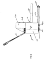
- Fig. 1-3 show a truck 1 with a load part 2 and a drive part 3 and a drawbar 4.
- the load part 2 has a middle load arm 25 with a rear Lastarmschreiben 26, which will be described later and is guided vertically adjustable in a mast.
- the drive member 3 has a central drive wheel 11 and laterally thereof two casters, one of which can be seen at 12.
- the drive member is also connected to a Radarm 13 which supports a load roller 10 at the free end.
- the truck shown for lifting and transporting small pallets 40 and 41 Like from the 4 and 5 shows, the truck shown for lifting and transporting small pallets 40 and 41.
- Fig. 5 It is shown how four small pallets are placed on a conventional large pallet 42, for example a Euro pallet.
- the wheel arm 13 can retract into the pallet 42, and the load arm 25 moves into the small pallet 40 and raises it, as in Fig. 5 shown. Subsequently, the truck 1 can drive out of the pallet 42 and transport the pallet 40 to a desired location.
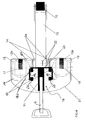
- a bearing member 23 is mounted vertically adjustable in the form of a plate on which rubber spring elements 20 are fixedly mounted on opposite sides of the longitudinal axis of the vehicle shown. Further rubber spring elements 60 are connected to a bearing plate, not shown, for a traction drive 19, not shown, of the industrial truck 1 shown. Between the rubber spring elements 20 and 60, links 62 are attached. In this way, a bias can be exerted on the drive bearing plate to press the drive wheel 11 with sufficient force against the ground.
- the bearing member 23, which is formed by a plate, is height-adjustable attached to the back of the mast sections 14 to change the bias.
- Fig. 7 It can be seen that two lithium batteries 31, 32 each are arranged on the support plates 16. Above the lithium batteries 31, 32 further lithium batteries 33 are arranged in a row, namely one above the batteries on the support plate 16 and a lithium battery aligned above the traction drive 19. A charger, not shown, the lithium batteries can be assigned to the batteries without a Remove or without charging an external charger.
- Fig. 7 is located at 30 an electric lift motor standing, which adjusts the load arm back 26 in height via a spindle drive.
- the spindle is indicated, which cooperates with a spindle nut, not shown, and is secured to parallel spaced tabs 34 on the back of the Lastarmrückens 26.
- the spindle nut is connected to the hoist motor via a gearbox.
- the articulation of the drawbar 4 is disposed above a panel 21 of the truck 1.
- the dot-dash line 64 indicates the steering axis 64 for actuating the steerable drive wheel 11.
- the panel 21 surrounds in the lower area the drive not shown further and the lithium batteries 31 and 32.
- a panel 29 is shown, which surrounds a room for the accommodation of batteries 33, controls for the drives, a battery management system and other components of the electrical system of the truck shown 1. It also an on-board charger can be accommodated, so that only an electrical outlet is required for an intermediate charge.
- On the outer sides of the panels 21, 29 display and controls can be arranged.
- the drawbar 4 is arranged so that pivoting by at least +/- 90 ° to the lower portion of the upper panel 29 is possible.
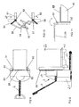
- load-holding elements 50, 51 are mounted pivotably about an axis 53 on the sides of the load-arm back 26.
- the load holders 50, 51 are shown at 52 in rest position. It can be seen that they are in the Essentially does not protrude beyond the outer contour of the vehicle. In the working position, the load holders 50, 51 are on the side of the pallet 40 and extend over a relatively large amount, beyond the fork back 26, to laterally support the load 66 resting on the pallet 40.
- Fig. 10 is an exemplary operation of the load-holding elements 50, 51 shown schematically.
- the load-holding elements 50, 51 which are elongated plate-shaped, arms 54, 55 are firmly connected.
- link arms 56, 57 are articulated, which in turn are articulated to a two-armed lever 58.
- the lever 58 is pivotable about a vertical axis 59.
- the pivot bearing is firmly connected to the Lastarmschreiben 26.
- FIG. 11 An alternative embodiment of load-retaining elements is in Fig. 11 indicated.
- An L-shaped load-holding element 63 is pivotally mounted about a vertical axis 61 on the load arm back 26. In the solid representation, the load-holding element 63 bears against the pallet 40. The rest position is shown in dashed lines. When adjusting the load-holding element 63 is to be pivoted by 180 °. It is therefore in the rest position on the outside of the panel 21 and 29 at. Again, it is only minimally on the outer contour of the vehicle over. In the load-holding element 63, a greater length of the load is secured than is the case with the load-holding elements 50, 51. The load holding elements 50, 51 and 63 are locked in their respective position in a suitable manner.
Landscapes
- Engineering & Computer Science (AREA)
- Transportation (AREA)
- Structural Engineering (AREA)
- Civil Engineering (AREA)
- Life Sciences & Earth Sciences (AREA)
- Geology (AREA)
- Mechanical Engineering (AREA)
- Forklifts And Lifting Vehicles (AREA)
- Handcart (AREA)
Abstract
Description
Die Erfindung bezieht sich auf ein Flurförderzeug zum Transport von Sonderpaletten nach Anspruch 1.The invention relates to an industrial truck for transporting special pallets according to
In der weltweiten Logistik haben sich Paletten als Ladehilfsmittel durchgesetzt. Eine Standardpalette (Europalette) hat eine Abmessung von 800 x 1200 Millimeter. Es sind auch andere Größen bekannt. Die Paletten werden vornehmlich von Flurförderzeugen transportiert und gestapelt, die mit Gabelzinken beziehungsweise Gabelarmen ausgelegt sind. Die übliche Ausführung ermöglicht lediglich den Transport einer Palette.In global logistics, pallets have become accepted as loading aids. A standard pallet (Euro pallet) has a dimension of 800 x 1200 millimeters. There are also other sizes known. The pallets are transported and stacked mainly by industrial trucks, which are designed with forks or fork arms. The usual design allows only the transport of a pallet.
In Einzelfällen (zum Beispiel im Einzelhandel) werden Lasten auf kleineren Paletten gestapelt und transportiert, die zum Beispiel die Abmessung von einem Viertel einer Europalette aufweisen. Die Waren werden, auf den Paletten stehend, direkt im Verkaufsraum aufgestellt. Um derartige Paletten zu handhaben, hat sich durchgesetzt, die kleineren Paletten so zu gestalten, dass sie jeweils die Hälfte, ein Drittel oder ein Viertel einer Standardpalette in Anspruch nehmen. Für die Lagerung in Regalen und den Transport werden Standardflurförderzeuge verwendet. Die kleineren Paletten sind auf Standardpaletten aufgestellt. Beim Einzelhändler müssen dann die kleineren Paletten von den großen heruntergenommen und in den Verkaufsraum gebracht werden.In isolated cases (for example in retail), loads are stacked and transported on smaller pallets, for example measuring one quarter of a Euro pallet. The goods are placed on the pallets, directly in the sales room. In order to handle such pallets, it has been accepted to make the smaller pallets so that they each occupy half, a third or a quarter of a standard pallet. For storage on shelves and transport standard trucks are used. The smaller pallets are set up on standard pallets. At the retailer, the smaller pallets must then be taken down by the big ones and taken to the showroom.
Für das Herunternehmen der kleinen Paletten von den großen und den Transport in den Verkaufsraum sind Spezialflurförderzeuge erforderlich. Sie müssen in der Lage sein, eine Stapelfunktion auszuführen, um die kleinen Paletten von den großen herunterzunehmen. Sie müssen außerdem in der Lage sein, die kleinen Paletten in den Verkaufsraum zu transportieren. Standardflurförderzeuge nehmen die kleinen Paletten jeweils auf einzelne Gabelzinken auf, was entsprechend unsicher ist. Außerdem benötigt ein Standardflurförderzeug zum Manövrieren viel Platz, der häufig nicht zur Verfügung steht.For the removal of the small pallets from the large ones and the transport to the sales area, special industrial trucks are required. she must be able to perform a stacking function to take down the small pallets from the big ones. You also need to be able to transport the small pallets into the sales room. Standard trucks take the small pallets on each individual forks, which is correspondingly uncertain. In addition, a standard truck for maneuvering requires a lot of space, which is often not available.
Es ist auch bereits bekannt, Kleinfahrzeuge vorzusehen, die mit einem mittigen Radarm und einem mittigen Lastarm versehen sind, um derartige Paletten zu transportieren und zu stapeln. Da die kleinen Paletten oftmals in Relation zu ihrer Grundfläche hoch beladen sind, ist es sinnvoll, die Unterstützung der Palette durch die einzelne Gabelzinke um weitere Elemente zu ergänzen. Es sind Haltewinkel bekannt, die am Gabelrücken so befestigt sind, dass sie die auf der Gabelzinke liegende Palette an den beiden, dem Gabelrücken zugewandten Ecken unterstützen. Dies setzt jedoch eine spezielle Ausführung der kleinen Paletten voraus, die meist nicht gegeben ist. In diesem Fall muss der Bediener die Handhabung der kleinen Paletten vorsichtig durchführen und gegebenenfalls die Last von Hand zusätzlich abstützen.It is also already known to provide small vehicles which are provided with a central wheel arm and a central load arm to transport and stack such pallets. Since the small pallets are often heavily loaded in relation to their base area, it makes sense to supplement the support of the pallet by the single fork to further elements. There are known brackets that are attached to the fork back so that they support the lying on the fork tine pallet at the two, the fork back facing corners. However, this requires a special design of the small pallets, which is usually not given. In this case, the operator must carefully handle the handling of the small pallets and optionally additionally support the load by hand.
Der Erfindung liegt die Aufgabe zugrunde, ein Flurförderzeug zum Transport von Sonderpaletten zu schaffen, das Stapel- und Transportvorgänge schnell und sicher mit wenig Platzbedarf und ohne große körperliche Anstrengung durchrühren kann.The invention has for its object to provide a truck for transporting special pallets that can quickly and safely stir stacking and transport operations with little space and without great physical effort.
Diese Aufgabe wird durch die Merkmale des Anspruchs 1 gelöst.This object is solved by the features of
Bei dem erfindungsgemäßen Flurförderzeug sind zwei parallel beabstandete Hubgerüstprofile seitlich am mittigen Radarm angeschweißt, vorzugsweise über Distanzklötze. Der Lastarmrücken ist in den Hubgerüstprofilen geführt, vorzugsweise über Rollen. Ein Lagerbauteil für einen Fahrantrieb mit einem schwenkbaren beziehungsweise lenkbaren Antriebsrad ist über gefederte Arme an den Hubgerüstprofilen angelenkt. Die Anlenkung erfolgt vorzugsweise an der Rückseite der Hubgerüstprofile.In the truck according to the invention two parallel spaced mast profiles are laterally welded to the central arm, preferably via spacer blocks. The load arm back is guided in the mast profiles, preferably via rollers. A bearing component for a traction drive with a pivotable or steerable drive wheel is articulated via sprung arms to the mast profiles. The articulation is preferably at the back of the mast profiles.
Das erfindungsgemäße Flurförderzeug weist mithin eine selbsttragende Konstruktion auf, die einfach herstellbar ist und zu einem leichten Gerät führt.The truck according to the invention thus has a self-supporting construction, which is easy to manufacture and leads to a lightweight device.
Vorteilhafte Ausgestaltungen des Anspruchs 1 sind in Unteransprüchen angegeben.Advantageous embodiments of
Nach einer Ausgestaltung der Erfindung sind an der Rückseite des Lastarmrückens parallel beabstandete Laschen angebracht für die Lagerung von Führungsrollen.According to one embodiment of the invention parallel spaced tabs are attached to the back of the Lastarmrückens for the storage of guide rollers.
Nach einer weiteren Ausgestaltung der Erfindung sind an einem an den Hubgerüstprofilen befestigten Haltebauteil beabstandet zwei Gummifederelementepaare eingebracht, die über Lenker mit Gummifederelementen am Lagerbauteil des Fahrantriebs gekoppelt sind. Ein Elementpaar kann jedoch auch durch ein einzelnes Element ersetzt werden, um eine Parallelführung zu erhalten. Derartige Gummifederelemente sind an sich bekannt. Sie bestehen aus einer äußeren und einer inneren Hülse, beispielsweise in Vierkantform wobei zwischen den Hülsen elastomeres Material eingebracht ist. Mit Hilfe einer derartigen Federanordnung wird für das Antriebsrad ein gewisser Bodenandruck erzeugt, der nach einer weiteren Ausgestaltung der Erfindung dadurch variabel ist, dass die Anbringung der ersten Federelemente in der Höhe an unterschiedlichen Orten gewählt werden kann.According to a further embodiment of the invention spaced two rubber spring element pairs are placed on a fixed to the mast profiles holding member, which are coupled via links with rubber spring elements on the bearing component of the traction drive. However, an element pair can also be replaced by a single element to obtain a parallel guide. Such rubber spring elements are known per se. They consist of an outer and an inner sleeve, for example in square shape with elastomeric between the sleeves Material is introduced. With the aid of such a spring arrangement, a certain Bodenandruck is generated for the drive wheel, which is variable according to a further embodiment of the invention characterized in that the attachment of the first spring elements in height can be selected at different locations.
Nach einer weiteren Ausgestaltung der Erfindung sind auf beiden Seiten der Hubgerüstprofile Lagerplatten an diesen angebracht, die an der Unterseite Lenkrollen lagern. Die Lagerplatten können nach einer weiteren Ausgestaltung der Erfindung Verbindungsstreben aufweisen, die ihrerseits mit den Hubprofilen verschweißt sein können. Die Lagerplatten dienen auch zur Abstützung von Batterien, vorzugsweise Lithiumzellen. Lithiumzellen beanspruchen bei gleichem nutzbarem Energieinhalt in Relation zu bisher üblichen Bleisäurebatterien wesentlich weniger Bauraum und sind außerdem leichter. Sie haben weiterhin den Vorteil, dass sie in einer kürzeren Zeit wieder geladen werden können als Bleisäurebatterien und im Gegensatz zu diesen wartungsfrei sind. Nach einer weiteren Ausgestaltung der Erfindung in diesem Zusammenhang ist vorgesehen, dass oberhalb der Lithiumzellen auf den Tragplatten weitere Lithiumzellen angeordnet sind, die mit einer Lithiumzelle oberhalb der Federanordnung für den Fahrantrieb ausgerichtet sind. Zum Erreichen einer Gesamtspannung von etwa 24 Volt sind daher vorzugsweise sieben dieser Zellen vorgesehen.According to a further embodiment of the invention bearing plates are attached to these on both sides of the mast profiles, which store at the bottom of castors. The bearing plates may comprise connecting struts according to a further embodiment of the invention, which in turn may be welded to the Hubprofilen. The bearing plates also serve to support batteries, preferably lithium cells. Lithium cells require much less space with the same useful energy content in relation to conventional lead-acid batteries and are also lighter. They also have the advantage that they can be recharged in a shorter time than lead-acid batteries and in contrast to these are maintenance-free. According to a further embodiment of the invention in this context, it is provided that above the lithium cells on the support plates further lithium cells are arranged, which are aligned with a lithium cell above the spring arrangement for the traction drive. To achieve a total voltage of about 24 volts, therefore, preferably seven of these cells are provided.
Das erfindungsgemäße Flurförderzeug weist auch eine Hubvorrichtung auf, um den Lastarm in der Höhe zu bewegen. Hierzu kann ein herkömmlicher Hydraulikantrieb genommen werden. Nach einer Ausgestaltung der Erfindung ist ein Spindelantrieb vorgesehen, dessen Elektromotor vorzugsweise parallel zur Spindel angeordnet ist und dessen Spindelmutter mit der Spindel zusammenwirkt, die mit zwei parallel beabstandeten weiteren Laschen an der Rückseite des Lastarmrückens in Wirkverbindung steht. Die Spindel ist vorzugsweise drehfest an den Laschen befestigt und der Motor treibt die Spindelmutter an. Ein Elektrospindelantrieb hat den Vorteil, dass dadurch ein "ölfreies" Fahrzeug erhalten wird, was insbesondere für einen Einsatz im Lebensmittelbereich von Vorteil ist. Vorzugsweise wird für den Fahrantrieb ein Direktantrieb vorgesehen. Ein Direktantrieb benötigt nur einen kleinen Bauraum und ist durch einen leisen Betrieb gekennzeichnet. Es kann jedoch auch ein Antrieb mit Getriebe, vorzugsweise bei ebenfalls liegendem Motor, vorgesehen werden.The truck according to the invention also has a lifting device to move the load arm in height. For this purpose, a conventional hydraulic drive can be taken. According to one embodiment of the invention, a spindle drive is provided, the electric motor preferably parallel is arranged to the spindle and the spindle nut cooperates with the spindle, which is in operative connection with two parallel spaced further tabs on the back of Lastarmrückens. The spindle is preferably rotatably attached to the tabs and the motor drives the spindle nut. An electric spindle drive has the advantage that an "oil-free" vehicle is thereby obtained, which is advantageous in particular for use in the food sector. Preferably, a direct drive is provided for the traction drive. A direct drive requires only a small space and is characterized by quiet operation. However, it can also be a drive with gear, preferably with also lying engine, are provided.
Die Lenkung des erfindungsgemäßen Flurförderzeugs kann über eine Deichsel erfolgen, wodurch das Fahrzeug als Mitgängerfahrzeug gekennzeichnet ist. Die Deichsel ist so gelagert, dass sie um mindestens +/-90° schwenkbar ist. Ihre Verbindung mit einer vorzugsweise vertikalen Lenkachse erfolgt vorzugsweise oberhalb von Fahrantrieb und Batterien. Alternativ kann auch eine Stehplattform mit dem Fahrzeug verbunden werden, die gegebenenfalls klappbar ist. Bei feststehender Stehplattform kann ein Lenkgeber von geringen Ausmaßen in Griffnähe angebracht sein, der über eine elektrische Lenkung das Antriebsrad lenkt.The steering of the truck according to the invention can take place via a drawbar, whereby the vehicle is characterized as a pedestrian vehicle. The drawbar is mounted so that it can be swiveled by at least +/- 90 °. Their connection with a preferably vertical steering axle is preferably carried out above the drive and batteries. Alternatively, a standing platform can be connected to the vehicle, which can be folded if necessary. In a fixed standing platform, a steering transmitter of small dimensions can be mounted close to the handle, which steers the drive wheel via an electric steering.
Nach einer anderen Ausgestaltung der Erfindung ist seitlich am Lastarmrücken jeweils ein Lasthalteelement angelenkt, das um eine annähernd vertikale Achse schwenkbar seitlich gegen eine von Lastarm aufgenommene Last anlegbar ist. Dadurch wird die Last auf der aufgenommenen Palette seitlich abgestützt. Die Lasthalteelemente werden nach dem Aufnehmen der kleinen Palette seitlich an diese herangeklappt, so dass der dem Antriebsteil zugewandte Teil der kleinen Palette und auch die darauf befindliche Ware seitlich zur Fahrtrichtung sicher gestützt werden kann. Höhe und Länge der Lasthalteelemente werden so gewählt, dass sie in der Ruheposition im Wesentlichen nicht über die Außenkontur des Fahrzeuges hinausragen.According to another embodiment of the invention, a load-holding element is articulated laterally on the load arm back, which can be applied laterally about an approximately vertical axis against a load received by the load arm. As a result, the load on the recorded pallet is supported laterally. The load-retaining elements become after receiving the small pallet folded laterally to this, so that the drive part facing part of the small range and also the goods located thereon can be safely supported laterally to the direction of travel. Height and length of the load-holding elements are chosen so that they do not protrude in the rest position substantially over the outer contour of the vehicle.
Die Vorteile des erfindungsgemäßen Flurförderzeugs wie folgt zusammengefasst werden:
- Verbesserung der Ergonomie bei der Handhabung von kleinen Paletten, insbesondere im Einzelhandel
- Entfall des Umpackens der kleinen Paletten nach Anlieferung und vor dem Transport in den Verkaufsraum
- Kompakte Bauform unter Nutzung neuer Antriebs- und Batterietechnologien
- Einsatz von Verschleiß- und wartungsfreien Federelementen zur Führung und Federung des Fahrantriebs, so dass jederzeit eine ausreichende Kraftübertragung zwischen Antriebsrad und Boden gegeben ist, insbesondere zum Bremsen, Antreiben und Lenken
- Erhöhung der Sicherheit für Bediener und Personen
- Keine Beschädigung der transportierten Ware und der Umgebung
- Bei Verwendung von Lithiumbatterien Wartungsfreiheit und große Vorteile bei der Fahrzeuggestaltung
- Ölfreies Fahrzeug.
- Improve ergonomics in handling small pallets, especially in retail
- No repacking of the small pallets after delivery and before transport to the salesroom
- Compact design using new drive and battery technologies
- Use of wear and maintenance-free spring elements for guiding and suspension of the traction drive, so that at any time sufficient power transmission between the drive wheel and ground is given, in particular for braking, driving and steering
- Increased safety for operators and people
- No damage to the transported goods and the environment
- When using lithium batteries maintenance-free and great advantages in vehicle design
- Oil-free vehicle.
Die Erfindung wird nachfolgend anhand eines Ausführungsbeispiels näher erläutert.
- Fig. 1
- zeigt schematisch die Draufsicht auf Flurförderzeug nach der Erfindung.
- Fig. 2
- zeigt die Seitenansicht des Flurförderzeugs nach
Fig. 1 . - Fig. 3
- zeigt das Flurförderzeug nach
Fig. 2 mit angehobenem Lastarm. - Fig. 4
- zeigt die Draufsicht auf ein Flurförderzeug nach
Fig. 1 beim Einfahren in eine kleine Palette, die mit drei anderen auf einer großen Palette aufgestellt ist. - Fig. 5
- zeigt die Seitenansicht der Anordnung nach
Fig. 4 beim Anheben einer kleinen Palette. - Fig. 6
- zeigt einen Schnitt durch das Fahrzeug nach
Fig. 2 kurz oberhalb des Radarms unter Weglassung des Lastarms. - Fig. 7
- zeigt einen Schnitt durch das Fahrzeug nach
Fig. 1 oberhalb des Lastarms beziehungsweise der aufgenommenen Batterien. - Fig. 8
- zeigt eine ähnliche Darstellung wie
Fig. 4 , jedoch zusätzlich mit Lasthalteelementen. - Fig. 9
- zeigt die Seitenansicht der Darstellung nach
Fig. 8 . - Fig. 10
- zeigt in einer Einzeldarstellung die Betätigung von Lasthalteelementen nach den
Fig. 8 und 9 . - Fig. 11
- zeigt eine Alternative zur Ausbildung eines Lasthalteelements.
- Fig. 1
- schematically shows the top view of the truck according to the invention.
- Fig. 2
- shows the side view of the truck
Fig. 1 , - Fig. 3
- shows the truck after
Fig. 2 with raised load arm. - Fig. 4
- shows the top view of an industrial truck
Fig. 1 when entering a small pallet placed with three others on a large pallet. - Fig. 5
- shows the side view of the arrangement
Fig. 4 when lifting a small pallet. - Fig. 6
- shows a section through the vehicle
Fig. 2 just above the wheel arm, omitting the load arm. - Fig. 7
- shows a section through the vehicle
Fig. 1 above the load arm or batteries. - Fig. 8
- shows a similar representation as
Fig. 4 , but additionally with load-holding elements. - Fig. 9
- shows the side view of the presentation
Fig. 8 , - Fig. 10
- shows in an individual view the operation of load-holding elements according to the
8 and 9 , - Fig. 11
- shows an alternative to the formation of a load-holding element.
Das Antriebsteil 3 weist ein mittiges Antriebsrad 11 auf und seitlich davon zwei Schwenkrollen, von denen eine bei 12 zu erkennen ist. Das Antriebsteil ist auch mit einem Radarm 13 verbunden, der am freien Ende eine Lastrolle 10 lagert.The
Wie aus den
Der Aufbau des in den obigen Figuren dargestellten Flurförderzeugs geht deutlicher aus den
In
In
Wie aus den
Die
In
Eine alternative Ausgestaltung von Lasthalteelementen ist in
Claims (18)
Applications Claiming Priority (1)
| Application Number | Priority Date | Filing Date | Title |
|---|---|---|---|
| DE200820013950 DE202008013950U1 (en) | 2008-10-18 | 2008-10-18 | Industrial truck for transporting special plates |
Publications (3)
| Publication Number | Publication Date |
|---|---|
| EP2177470A2 true EP2177470A2 (en) | 2010-04-21 |
| EP2177470A3 EP2177470A3 (en) | 2011-05-11 |
| EP2177470B1 EP2177470B1 (en) | 2012-05-23 |
Family
ID=40340408
Family Applications (1)
| Application Number | Title | Priority Date | Filing Date |
|---|---|---|---|
| EP20090013125 Not-in-force EP2177470B1 (en) | 2008-10-18 | 2009-10-16 | Industrial truck for transporting special palettes |
Country Status (2)
| Country | Link |
|---|---|
| EP (1) | EP2177470B1 (en) |
| DE (1) | DE202008013950U1 (en) |
Citations (4)
| Publication number | Priority date | Publication date | Assignee | Title |
|---|---|---|---|---|
| US2992749A (en) * | 1960-10-17 | 1961-07-18 | Themus A Spillios | Method of handling strip or bar materials |
| EP0958988A2 (en) * | 1998-05-18 | 1999-11-24 | BT Industries Aktiebolag | Device for increasing the supporting surface of a load fork |
| US6125971A (en) * | 1995-09-13 | 2000-10-03 | Jungheinrich Aktiengesellschaft | Forklift truck |
| WO2006059940A1 (en) * | 2004-11-06 | 2006-06-08 | Bt Industries | Truck mast |
-
2008
- 2008-10-18 DE DE200820013950 patent/DE202008013950U1/en not_active Expired - Lifetime
-
2009
- 2009-10-16 EP EP20090013125 patent/EP2177470B1/en not_active Not-in-force
Patent Citations (4)
| Publication number | Priority date | Publication date | Assignee | Title |
|---|---|---|---|---|
| US2992749A (en) * | 1960-10-17 | 1961-07-18 | Themus A Spillios | Method of handling strip or bar materials |
| US6125971A (en) * | 1995-09-13 | 2000-10-03 | Jungheinrich Aktiengesellschaft | Forklift truck |
| EP0958988A2 (en) * | 1998-05-18 | 1999-11-24 | BT Industries Aktiebolag | Device for increasing the supporting surface of a load fork |
| WO2006059940A1 (en) * | 2004-11-06 | 2006-06-08 | Bt Industries | Truck mast |
Also Published As
| Publication number | Publication date |
|---|---|
| DE202008013950U8 (en) | 2009-06-10 |
| DE202008013950U1 (en) | 2009-02-05 |
| EP2177470B1 (en) | 2012-05-23 |
| EP2177470A3 (en) | 2011-05-11 |
Similar Documents
| Publication | Publication Date | Title |
|---|---|---|
| DE102015107102A1 (en) | Mecanum wheel vehicle and operating procedures | |
| EP1907310B1 (en) | Trailer for a motor vehicle | |
| DE102018112568A1 (en) | Truck with retractable and retractable auxiliary wheel | |
| EP2570358A2 (en) | Transport system for transport containers or lattice boxes | |
| EP2061676A1 (en) | Platform for carrying and transporting loads with an unrollable floor, and transport device with a platform of this type | |
| DE4126728C2 (en) | Lifting and conveying vehicle | |
| EP3730450B1 (en) | Carriage with initial stroke | |
| DE202011105716U1 (en) | Transport system for transport containers or lattice boxes | |
| DE102018112566A1 (en) | Truck with extendable structure | |
| EP2177470B1 (en) | Industrial truck for transporting special palettes | |
| EP2135792B1 (en) | Transport device | |
| EP1466860B1 (en) | Construction kit for the building of load-handling trucks | |
| DE102017008813A1 (en) | Hand truck with several axles, especially for transporting gas cylinders made of steel | |
| EP2518005B1 (en) | Industrial truck | |
| DE102016104745A1 (en) | Pedestrian-controlled pallet truck | |
| DE102019112580A1 (en) | Industrial truck | |
| EP1116686A2 (en) | Industrial truck | |
| DE10251398A1 (en) | Transporting unit has two side running wheels mounted on underside of pallet close to one end, while at other end of pallet there is load pick-up coupling which engages with liftable load holding adaptor on floor conveyor | |
| EP0951416B1 (en) | Sack trolley for transporting loads | |
| EP3147255B1 (en) | Exchange device for traction battery of an industrial truck | |
| DE102015108993A1 (en) | Broad gauge stacker | |
| DE102015116346A1 (en) | Replacement device for traction battery of a truck | |
| WO2020229018A1 (en) | Industrial truck | |
| EP2479134A1 (en) | Device for making it easier to maintain vehicles | |
| EP3969406A1 (en) | Industrial truck |
Legal Events
| Date | Code | Title | Description |
|---|---|---|---|
| PUAI | Public reference made under article 153(3) epc to a published international application that has entered the european phase |
Free format text: ORIGINAL CODE: 0009012 |
|
| AK | Designated contracting states |
Kind code of ref document: A2 Designated state(s): AT BE BG CH CY CZ DE DK EE ES FI FR GB GR HR HU IE IS IT LI LT LU LV MC MK MT NL NO PL PT RO SE SI SK SM TR |
|
| AX | Request for extension of the european patent |
Extension state: AL BA RS |
|
| PUAL | Search report despatched |
Free format text: ORIGINAL CODE: 0009013 |
|
| AK | Designated contracting states |
Kind code of ref document: A3 Designated state(s): AT BE BG CH CY CZ DE DK EE ES FI FR GB GR HR HU IE IS IT LI LT LU LV MC MK MT NL NO PL PT RO SE SI SK SM TR |
|
| AX | Request for extension of the european patent |
Extension state: AL BA RS |
|
| 17P | Request for examination filed |
Effective date: 20111111 |
|
| REG | Reference to a national code |
Ref country code: DE Ref legal event code: R079 Ref document number: 502009003585 Country of ref document: DE Free format text: PREVIOUS MAIN CLASS: B66F0009080000 Ipc: B66F0009120000 |
|
| GRAP | Despatch of communication of intention to grant a patent |
Free format text: ORIGINAL CODE: EPIDOSNIGR1 |
|
| RIC1 | Information provided on ipc code assigned before grant |
Ipc: B66F 9/08 20060101ALI20120130BHEP Ipc: B66F 9/12 20060101AFI20120130BHEP |
|
| GRAS | Grant fee paid |
Free format text: ORIGINAL CODE: EPIDOSNIGR3 |
|
| GRAA | (expected) grant |
Free format text: ORIGINAL CODE: 0009210 |
|
| AK | Designated contracting states |
Kind code of ref document: B1 Designated state(s): AT BE BG CH CY CZ DE DK EE ES FI FR GB GR HR HU IE IS IT LI LT LU LV MC MK MT NL NO PL PT RO SE SI SK SM TR |
|
| REG | Reference to a national code |
Ref country code: GB Ref legal event code: FG4D Free format text: NOT ENGLISH |
|
| REG | Reference to a national code |
Ref country code: CH Ref legal event code: EP |
|
| REG | Reference to a national code |
Ref country code: AT Ref legal event code: REF Ref document number: 558991 Country of ref document: AT Kind code of ref document: T Effective date: 20120615 |
|
| REG | Reference to a national code |
Ref country code: IE Ref legal event code: FG4D Free format text: LANGUAGE OF EP DOCUMENT: GERMAN |
|
| REG | Reference to a national code |
Ref country code: DE Ref legal event code: R096 Ref document number: 502009003585 Country of ref document: DE Effective date: 20120719 |
|
| REG | Reference to a national code |
Ref country code: SE Ref legal event code: TRGR |
|
| REG | Reference to a national code |
Ref country code: NL Ref legal event code: VDEP Effective date: 20120523 |
|
| REG | Reference to a national code |
Ref country code: LT Ref legal event code: MG4D Effective date: 20120523 |
|
| PG25 | Lapsed in a contracting state [announced via postgrant information from national office to epo] |
Ref country code: CY Free format text: LAPSE BECAUSE OF FAILURE TO SUBMIT A TRANSLATION OF THE DESCRIPTION OR TO PAY THE FEE WITHIN THE PRESCRIBED TIME-LIMIT Effective date: 20120523 Ref country code: FI Free format text: LAPSE BECAUSE OF FAILURE TO SUBMIT A TRANSLATION OF THE DESCRIPTION OR TO PAY THE FEE WITHIN THE PRESCRIBED TIME-LIMIT Effective date: 20120523 Ref country code: IS Free format text: LAPSE BECAUSE OF FAILURE TO SUBMIT A TRANSLATION OF THE DESCRIPTION OR TO PAY THE FEE WITHIN THE PRESCRIBED TIME-LIMIT Effective date: 20120923 Ref country code: NO Free format text: LAPSE BECAUSE OF FAILURE TO SUBMIT A TRANSLATION OF THE DESCRIPTION OR TO PAY THE FEE WITHIN THE PRESCRIBED TIME-LIMIT Effective date: 20120823 Ref country code: LT Free format text: LAPSE BECAUSE OF FAILURE TO SUBMIT A TRANSLATION OF THE DESCRIPTION OR TO PAY THE FEE WITHIN THE PRESCRIBED TIME-LIMIT Effective date: 20120523 |
|
| PG25 | Lapsed in a contracting state [announced via postgrant information from national office to epo] |
Ref country code: GR Free format text: LAPSE BECAUSE OF FAILURE TO SUBMIT A TRANSLATION OF THE DESCRIPTION OR TO PAY THE FEE WITHIN THE PRESCRIBED TIME-LIMIT Effective date: 20120824 Ref country code: HR Free format text: LAPSE BECAUSE OF FAILURE TO SUBMIT A TRANSLATION OF THE DESCRIPTION OR TO PAY THE FEE WITHIN THE PRESCRIBED TIME-LIMIT Effective date: 20120523 Ref country code: LV Free format text: LAPSE BECAUSE OF FAILURE TO SUBMIT A TRANSLATION OF THE DESCRIPTION OR TO PAY THE FEE WITHIN THE PRESCRIBED TIME-LIMIT Effective date: 20120523 Ref country code: SI Free format text: LAPSE BECAUSE OF FAILURE TO SUBMIT A TRANSLATION OF THE DESCRIPTION OR TO PAY THE FEE WITHIN THE PRESCRIBED TIME-LIMIT Effective date: 20120523 Ref country code: PT Free format text: LAPSE BECAUSE OF FAILURE TO SUBMIT A TRANSLATION OF THE DESCRIPTION OR TO PAY THE FEE WITHIN THE PRESCRIBED TIME-LIMIT Effective date: 20120924 |
|
| PG25 | Lapsed in a contracting state [announced via postgrant information from national office to epo] |
Ref country code: CZ Free format text: LAPSE BECAUSE OF FAILURE TO SUBMIT A TRANSLATION OF THE DESCRIPTION OR TO PAY THE FEE WITHIN THE PRESCRIBED TIME-LIMIT Effective date: 20120523 Ref country code: NL Free format text: LAPSE BECAUSE OF FAILURE TO SUBMIT A TRANSLATION OF THE DESCRIPTION OR TO PAY THE FEE WITHIN THE PRESCRIBED TIME-LIMIT Effective date: 20120523 Ref country code: RO Free format text: LAPSE BECAUSE OF FAILURE TO SUBMIT A TRANSLATION OF THE DESCRIPTION OR TO PAY THE FEE WITHIN THE PRESCRIBED TIME-LIMIT Effective date: 20120523 Ref country code: DK Free format text: LAPSE BECAUSE OF FAILURE TO SUBMIT A TRANSLATION OF THE DESCRIPTION OR TO PAY THE FEE WITHIN THE PRESCRIBED TIME-LIMIT Effective date: 20120523 Ref country code: EE Free format text: LAPSE BECAUSE OF FAILURE TO SUBMIT A TRANSLATION OF THE DESCRIPTION OR TO PAY THE FEE WITHIN THE PRESCRIBED TIME-LIMIT Effective date: 20120523 Ref country code: SK Free format text: LAPSE BECAUSE OF FAILURE TO SUBMIT A TRANSLATION OF THE DESCRIPTION OR TO PAY THE FEE WITHIN THE PRESCRIBED TIME-LIMIT Effective date: 20120523 |
|
| PG25 | Lapsed in a contracting state [announced via postgrant information from national office to epo] |
Ref country code: IT Free format text: LAPSE BECAUSE OF FAILURE TO SUBMIT A TRANSLATION OF THE DESCRIPTION OR TO PAY THE FEE WITHIN THE PRESCRIBED TIME-LIMIT Effective date: 20120523 Ref country code: PL Free format text: LAPSE BECAUSE OF FAILURE TO SUBMIT A TRANSLATION OF THE DESCRIPTION OR TO PAY THE FEE WITHIN THE PRESCRIBED TIME-LIMIT Effective date: 20120523 |
|
| PLBE | No opposition filed within time limit |
Free format text: ORIGINAL CODE: 0009261 |
|
| STAA | Information on the status of an ep patent application or granted ep patent |
Free format text: STATUS: NO OPPOSITION FILED WITHIN TIME LIMIT |
|
| BERE | Be: lapsed |
Owner name: JUNGHEINRICH A.G. Effective date: 20121031 |
|
| PG25 | Lapsed in a contracting state [announced via postgrant information from national office to epo] |
Ref country code: ES Free format text: LAPSE BECAUSE OF FAILURE TO SUBMIT A TRANSLATION OF THE DESCRIPTION OR TO PAY THE FEE WITHIN THE PRESCRIBED TIME-LIMIT Effective date: 20120903 |
|
| 26N | No opposition filed |
Effective date: 20130226 |
|
| PG25 | Lapsed in a contracting state [announced via postgrant information from national office to epo] |
Ref country code: MC Free format text: LAPSE BECAUSE OF NON-PAYMENT OF DUE FEES Effective date: 20121031 |
|
| REG | Reference to a national code |
Ref country code: DE Ref legal event code: R097 Ref document number: 502009003585 Country of ref document: DE Effective date: 20130226 |
|
| REG | Reference to a national code |
Ref country code: IE Ref legal event code: MM4A |
|
| PG25 | Lapsed in a contracting state [announced via postgrant information from national office to epo] |
Ref country code: IE Free format text: LAPSE BECAUSE OF NON-PAYMENT OF DUE FEES Effective date: 20121016 Ref country code: BE Free format text: LAPSE BECAUSE OF NON-PAYMENT OF DUE FEES Effective date: 20121031 Ref country code: BG Free format text: LAPSE BECAUSE OF FAILURE TO SUBMIT A TRANSLATION OF THE DESCRIPTION OR TO PAY THE FEE WITHIN THE PRESCRIBED TIME-LIMIT Effective date: 20120823 |
|
| PG25 | Lapsed in a contracting state [announced via postgrant information from national office to epo] |
Ref country code: MT Free format text: LAPSE BECAUSE OF FAILURE TO SUBMIT A TRANSLATION OF THE DESCRIPTION OR TO PAY THE FEE WITHIN THE PRESCRIBED TIME-LIMIT Effective date: 20120523 |
|
| PG25 | Lapsed in a contracting state [announced via postgrant information from national office to epo] |
Ref country code: TR Free format text: LAPSE BECAUSE OF FAILURE TO SUBMIT A TRANSLATION OF THE DESCRIPTION OR TO PAY THE FEE WITHIN THE PRESCRIBED TIME-LIMIT Effective date: 20120523 |
|
| PG25 | Lapsed in a contracting state [announced via postgrant information from national office to epo] |
Ref country code: LU Free format text: LAPSE BECAUSE OF NON-PAYMENT OF DUE FEES Effective date: 20121016 Ref country code: SM Free format text: LAPSE BECAUSE OF FAILURE TO SUBMIT A TRANSLATION OF THE DESCRIPTION OR TO PAY THE FEE WITHIN THE PRESCRIBED TIME-LIMIT Effective date: 20120523 |
|
| REG | Reference to a national code |
Ref country code: CH Ref legal event code: PL |
|
| GBPC | Gb: european patent ceased through non-payment of renewal fee |
Effective date: 20131016 |
|
| PG25 | Lapsed in a contracting state [announced via postgrant information from national office to epo] |
Ref country code: CH Free format text: LAPSE BECAUSE OF NON-PAYMENT OF DUE FEES Effective date: 20131031 Ref country code: HU Free format text: LAPSE BECAUSE OF FAILURE TO SUBMIT A TRANSLATION OF THE DESCRIPTION OR TO PAY THE FEE WITHIN THE PRESCRIBED TIME-LIMIT Effective date: 20091016 Ref country code: GB Free format text: LAPSE BECAUSE OF NON-PAYMENT OF DUE FEES Effective date: 20131016 Ref country code: LI Free format text: LAPSE BECAUSE OF NON-PAYMENT OF DUE FEES Effective date: 20131031 |
|
| PG25 | Lapsed in a contracting state [announced via postgrant information from national office to epo] |
Ref country code: MK Free format text: LAPSE BECAUSE OF FAILURE TO SUBMIT A TRANSLATION OF THE DESCRIPTION OR TO PAY THE FEE WITHIN THE PRESCRIBED TIME-LIMIT Effective date: 20120523 |
|
| REG | Reference to a national code |
Ref country code: FR Ref legal event code: PLFP Year of fee payment: 7 |
|
| REG | Reference to a national code |
Ref country code: AT Ref legal event code: MM01 Ref document number: 558991 Country of ref document: AT Kind code of ref document: T Effective date: 20141016 |
|
| PG25 | Lapsed in a contracting state [announced via postgrant information from national office to epo] |
Ref country code: AT Free format text: LAPSE BECAUSE OF NON-PAYMENT OF DUE FEES Effective date: 20141016 |
|
| REG | Reference to a national code |
Ref country code: FR Ref legal event code: PLFP Year of fee payment: 8 |
|
| REG | Reference to a national code |
Ref country code: FR Ref legal event code: PLFP Year of fee payment: 9 |
|
| REG | Reference to a national code |
Ref country code: FR Ref legal event code: PLFP Year of fee payment: 10 |
|
| PGFP | Annual fee paid to national office [announced via postgrant information from national office to epo] |
Ref country code: SE Payment date: 20181029 Year of fee payment: 10 |
|
| PGFP | Annual fee paid to national office [announced via postgrant information from national office to epo] |
Ref country code: FR Payment date: 20181030 Year of fee payment: 10 |
|
| PGFP | Annual fee paid to national office [announced via postgrant information from national office to epo] |
Ref country code: DE Payment date: 20181228 Year of fee payment: 10 |
|
| REG | Reference to a national code |
Ref country code: DE Ref legal event code: R119 Ref document number: 502009003585 Country of ref document: DE |
|
| PG25 | Lapsed in a contracting state [announced via postgrant information from national office to epo] |
Ref country code: DE Free format text: LAPSE BECAUSE OF NON-PAYMENT OF DUE FEES Effective date: 20200501 |
|
| PG25 | Lapsed in a contracting state [announced via postgrant information from national office to epo] |
Ref country code: SE Free format text: LAPSE BECAUSE OF NON-PAYMENT OF DUE FEES Effective date: 20191017 |
|
| PG25 | Lapsed in a contracting state [announced via postgrant information from national office to epo] |
Ref country code: FR Free format text: LAPSE BECAUSE OF NON-PAYMENT OF DUE FEES Effective date: 20191031 |