EP2177046B2 - Ensemble microphone et récepteur combiné pour des dispositifs auditifs de canal à port étendu - Google Patents
Ensemble microphone et récepteur combiné pour des dispositifs auditifs de canal à port étendu Download PDFInfo
- Publication number
- EP2177046B2 EP2177046B2 EP08797823.5A EP08797823A EP2177046B2 EP 2177046 B2 EP2177046 B2 EP 2177046B2 EP 08797823 A EP08797823 A EP 08797823A EP 2177046 B2 EP2177046 B2 EP 2177046B2
- Authority
- EP
- European Patent Office
- Prior art keywords
- hearing device
- speaker
- microphone
- ear canal
- hearing
- Prior art date
- Legal status (The legal status is an assumption and is not a legal conclusion. Google has not performed a legal analysis and makes no representation as to the accuracy of the status listed.)
- Not-in-force
Links
Images


Classifications
-
- H—ELECTRICITY
- H04—ELECTRIC COMMUNICATION TECHNIQUE
- H04R—LOUDSPEAKERS, MICROPHONES, GRAMOPHONE PICK-UPS OR LIKE ACOUSTIC ELECTROMECHANICAL TRANSDUCERS; DEAF-AID SETS; PUBLIC ADDRESS SYSTEMS
- H04R25/00—Deaf-aid sets, i.e. electro-acoustic or electro-mechanical hearing aids; Electric tinnitus maskers providing an auditory perception
- H04R25/02—Deaf-aid sets, i.e. electro-acoustic or electro-mechanical hearing aids; Electric tinnitus maskers providing an auditory perception adapted to be supported entirely by ear
-
- H—ELECTRICITY
- H04—ELECTRIC COMMUNICATION TECHNIQUE
- H04R—LOUDSPEAKERS, MICROPHONES, GRAMOPHONE PICK-UPS OR LIKE ACOUSTIC ELECTROMECHANICAL TRANSDUCERS; DEAF-AID SETS; PUBLIC ADDRESS SYSTEMS
- H04R25/00—Deaf-aid sets, i.e. electro-acoustic or electro-mechanical hearing aids; Electric tinnitus maskers providing an auditory perception
- H04R25/45—Prevention of acoustic reaction, i.e. acoustic oscillatory feedback
- H04R25/456—Prevention of acoustic reaction, i.e. acoustic oscillatory feedback mechanically
-
- H—ELECTRICITY
- H04—ELECTRIC COMMUNICATION TECHNIQUE
- H04R—LOUDSPEAKERS, MICROPHONES, GRAMOPHONE PICK-UPS OR LIKE ACOUSTIC ELECTROMECHANICAL TRANSDUCERS; DEAF-AID SETS; PUBLIC ADDRESS SYSTEMS
- H04R2225/00—Details of deaf aids covered by H04R25/00, not provided for in any of its subgroups
- H04R2225/023—Completely in the canal [CIC] hearing aids
Definitions
- the present invention relates to hearing devices. More specifically, the present invention relates to hearing devices that are worn entirely in the ear canal for extended wear without daily insertion and removal as required with conventional hearing aids.
- the external acoustic meatus is generally narrow and contoured as shown in the coronal view in Fig. 1 .
- the ear canal 10 is axially approximately 25 mm in length from the canal aperture 15 to the tympanic membrane or eardrum 18.
- the lateral part, the part away from the tympanic membrane, of the ear canal comprises a cartilaginous region 11.
- Cartilaginous region 11 is relatively soft due to the underlying cartilaginous tissue.
- Cartilaginous region 11 of the ear canal 10 deforms and moves in response to the mandibular or jaw motions, which occur during talking, yawning, eating, etc.
- the medial part, the part toward the tympanic membrane comprises a bony region 12.
- Bony region 12 is proximal to the tympanic membrane and is rigid. Bony region 12 or the "bony canal" is roughly 15 mm long, representing approximately 60% of the canal length. The skin in the bony region 12 is thin relative to the skin in the cartilaginous region and thus more sensitive to touch or pressure. There is a characteristic bend that occurs approximately at the bony-cartilaginous junction 17, which separates cartilaginous region 11 and from bony region 12.
- Physiologic debris includes cerumen or earwax, sweat, decayed hair, and oils produced by the various glands underneath the skin in the cartilaginous region.
- Non-physiologic debris is also present and may consist of environmental particles, including hygienic and cosmetic products, that may have entered the ear canal. Canal debris is naturally extruded to the outside of the ear by the process of lateral epithelial cell migration, offering a natural self-cleansing mechanism for the ear.
- the ear canal 10 terminates medially with the tympanic membrane 18. Lateral of and external to the ear canal is the concha cavity 2 and the auricle 4, which is cartilaginous. The junction between the concha cavity 2 and cartilaginous region 11 of the ear canal at the aperture 15 is also defined by a characteristic bend 7, which is known as the first bend of the ear canal. Canal shape and dimensions can vary significantly among individuals.
- bony region 12 When compared to cartilaginous region 11, bony region 12 is dimensionally more stable since the underlying tissue is osseous and also physiologically less active due to the absence of hair, cerumen or sweat glands, present only in the cartilaginous portion.
- Extended wear hearing devices such as those described in U.S. Pat. No 7,215,789 to Shennib et al. , U.S., Pat. No 6,940,988 to Shennib et al. , U.S. Pat. No 6,473,513 also to Shennib et al. , are worn continuously from several weeks to several months inside the ear canal.
- These devices as taught by Shennib et al., may be miniature in size in order to fit entirely within the ear canal and are adapted for the receiver to fit deeply in the ear canal in proximity to the tympanic membrane (TM). However, the devices as taught may extend into the cartilaginous portion of the ear canal.
- An optimized placement for these devices is entirely in the bony part of the ear canal, avoiding placement in the cartilaginous portion of the ear canal. Placement in this manner may be desirable for many reasons including: (1) stability - because the bony part is immobile and the cartilaginous part is subject to movements and deformations, which can interfere with the hearing device by moving it or dislodging it from its intended position; (2) comfort of wear - canal interference with the hearing device can cause discomfort, irritation and even laceration of the ear canal; and (3) device longevity - because physiological debris is present primarily in the cartilaginous part of the ear canal, placement of the device in the bony canal can reduce the probability of contamination by debris in the canal.
- the hearing device In order to avoid placement of the device in the cartilaginous area of the ear canal, the hearing device should be made sufficiently short to fit only in the bony part between the junction 17 and the tympanic membrane 18. Therefore, the hearing device should be considerably shorter than 15 mm to fit most individuals in the bony region only and allowing for safe distance from the tympanic membrane. Many hearing devices, including the extended wear devices mentioned above, are too long and do not fit entirely in the bony canal. Many inventions provide various methods for dealing with partial placement in the cartilaginous part of the ear canal. These methods include the suspension of a lateral assembly and articulation of the device as will be discussed in more details below.
- Hearing aid receiver may be highly miniaturized but sufficiently sized to efficiently produce amplified sound to the tympanic membrane.
- These speakers are generally in the shape of a rectangular prism with lengths in the range of 5-7 mm and 2-3 mm in girth at the narrowest dimension. These speakers confer substantial length to the hearing device. Smaller dimensions are possible to manufacture but generally lead to undesirable reduction in output efficiency and are thus not currently commercially available. The reduction in output efficiency may not be acceptable for hearing aid manufacturers since the output efficiency reduction may necessitate increasing the power consumption significantly to produce the required amplification level for a hearing impaired individual. Examples of miniature hearing aid speakers include FH and FK series receivers made by Knowles Electronics and series 2600 made by Sonion (Denmark).
- Miniature microphones for hearing aids also exist with form factors that confer length or bulk to the miniature hearing devices. These minature microphones are generally in rectangular prism shape or in cylindrical shape, ranging from 2.5-5 in length to 1.3- to 2.6 mm in the narrowest dimension. Examples of miniature microphone include FG and TO series by Knowles Electronics, series 6000 by Sonion, and series 151 by Tibbetts Industries. Electret type microphones are widely used in hearing aids for their superior sensitivity, low noise characteristics and wide dynamic range. Electret type microphones can also have good vibration rejection characteristics for minimizing the effects of speaker or shell-conducted vibrations. Silicon microphones, not yet widely used, promise improved miniaturization and reduced vibration sensitivity. Similarly, smaller microphones can be manufactured but generally at the expense of reduced sensitivity and increased noise levels. Resorting to smaller microphone with inferior specifications is seldom acceptable by hearing impaired users who demand improved sound fidelity.
- the transducers In canal hearing aid devices, conventional and extended wear types, the transducers (speaker and microphone) are positioned with extreme care with respect to one another to minimize the occurrence of internal and external "feedback" generation.
- Feedback is the unwanted whistling in a hearing device due to the coupling between the microphone and receiver. Basically, feedback occurs when a portion of the output energy from the receiver reaches the microphone and causes a self-sustained oscillation.
- causes and mitigation of feedback in hearing devices are discussed in more details in columns 9 and 10 of U.S. Patent No. 5,701,348 .
- the opportunity for feedback is directly proportional to the acoustic gain (volume) and may thus be more likely to occur in hearing devices for persons with significant hearing losses. Feedback is also more likely to occur as the device gets smaller due to the reduction of the distance and increased coupling between the transducers.
- the speaker and the microphone can be placed with maximum axial spatial separation to minimize sound and vibration cross coupling.
- the speaker or receiver is placed most medially toward the tympanic membrane and the microphone is placed most laterally toward the aperture 15 of the ear canal.
- Another method used in hearing devices to minimize feedback is the use of damping material to suspend or isolate the microphone and the speaker within the housing of the device, for example, by using viscoelastic material to encapsulate vibration sensitive components or by filling the space within the hearing device as described in U.S. Patent No. 4,969,534 .
- damping material to suspend or isolate the microphone and the speaker within the housing of the device, for example, by using viscoelastic material to encapsulate vibration sensitive components or by filling the space within the hearing device as described in U.S. Patent No. 4,969,534 .
- maximum spatial separation between the transducers is often necessary for the mitigation of feedback. This separation requirement may result in hearing devices considerably longer than 12 mm when considering other components needed to operate the device such as battery, amplifiers, electronic circuits, mounting parts, etc. Lengths in excess of 12 mm may be acceptable for a user-inserted hearing devices which may also be referred to here as daily wear devices.
- mitigation of canal interference may be accomplished by suspending (in a non-contact or minimum contact fashion) the lateral assembly within the cartilaginous canal.
- the suspension may provide clearance for the device most of the time but occasionally the user may experience transient interference, for example, during yawing or sleeping on the ear, which may lead to device movement and in some cases discomfort.
- transient interference can cause irritation of the skin in the bony canal, which is extremely sensitive to touch and movements.
- Large device movements due to canal deformations can also lead to dislodgment of the device from its intended position. Interference and device movements usually necessitate the untimely removal of the device from the ear canal prior to device end of life.
- prior extended wear devices may use articulated assemblies with flexibly joints, for example, flexible connection 79 in commonly owned U.S. Patent No. 7,215,789 .
- This articulation can allow the lateral assembly to move in response to canal deformations or due to accumulation of debris in the cartilaginous portion.
- this articulation often adds length, cost and complexity to the manufacturing process of the device.
- WO 96/07295 A1 relates to a CIC hearing aid to be deeply placed within the ear channel and comprising a speaker at the medial end and a microphone at the lateral end.
- GB 2 098 426 A relates to an ITE hearing aid comprising a speaker located in the medial part of the hearing aid and having a diaphragm and a microphone located in the lateral part of the hearing aid and having a diaphragm, wherein the speaker diaphragm and the microphone diaphragm are oriented at an angle, such as a right angle, relative to each other in order to minimize interference between the speaker and the microphone in order to prevent acoustic feedback.
- WO 2005/115053 A1 relates to a dual diaphragm electroacoustic transducer.
- Another objective is to provide an extended wear canal device which is not susceptible to canal movements and deformation present in the cartilaginous canal.
- Another objective of this invention is to provide a hearing device that is 12 mm or less in length for fitting substantially in the bony part of the ear canal past the bony-cartilaginous junction when inserted within.
- Another objective of this invention is to provide an arrangement for an extended wear canal device without articulation for improved cost and reliability and shorter length.
- Embodiments of the invention provide an ultra miniature hearing device adapted to be worn for extended periods entirely in the ear canal past the cartilaginous region.
- the small size of the hearing device and its placement entirely within the ear canal provides a user with a more aesthetically pleasing and more natural appearance.
- the hearing device is adapted to be placed in the bony part of the ear canal, preferably by a physician or hearing professional. Placement of the device in the bony part of the hearing canal allows the hearing device to maintain a stable position and provide a comfortable fit by avoiding canal movements and deformations present in the cartilaginous region of the ear canal.
- the hearing device comprises a microphone having a microphone diaphragm and a speaker having a speaker diaphragm.
- the microphone is placed axially in parallel to the speaker, thereby reducing the space occupied by the hearing device.
- the microphone and speaker are arranged so that the microphone diaphragm is substantially orthogonal to the speaker diaphragm, thus minimizing the sensitivity of the microphone to vibrations produced by the receiver.
- lateral refers to the direction and parts of hearing devices which face away from the tympanic membrane.
- medial refers to the direction and parts of hearing devices which face toward tympanic membrane.
- the hearing device comprises (a) a power source, (b) an amplifier, (c) a microphone, and (d) a speaker.
- the microphone has a microphone diaphragm responsive to sound entering the ear canal.
- the speaker has a speaker diaphragm for generating amplified sound.
- the microphone and speaker are combined adjacently in an assembly disposed within a lateral portion of the hearing device and arranged so as to minimize cross vibrations from the speaker to the microphone when the speaker is excited by said amplifier.
- the speaker and said microphone are arranged so that the microphone diaphragm and the speaker diaphragm are positioned in substantially orthogonal planes.
- the power source may comprise a battery optionally having oval cross section and tapered medial end.
- an acoustic output of said speaker is acoustically coupled to a residual volume between a medial end of the hearing device and the tympanic membrane via a narrow sound conducting channel.
- the sound conducting channel may comprise a tube optionally having D-shaped cross section having an inside short diameter of 1 mm or less.
- the hearing device has a length 12 mm or less as measured from a lateral end to a medial end of the hearing device when the hearing device is placed entirely in the ear canal for extended wear therein.
- the microphone and speaker are disposed at the lateral end, often forming the lateral end.
- the hearing device is adapted to be placed entirely in the bony part of the ear canal.
- the speaker may comprise a dual diaphragm for reducing speaker case vibrations.
- the hearing device may be adapted to be disposable and discarded after at least two months of wear in the ear canal.
- the components within the hearing device may be encapsulated and proofed to withstand water and debris present in the ear canal.
- the hearing device may further comprise a viscoelastic damper disposed between the microphone and the speaker.
- the viscoelastic damper is adapted to reduce vibration coupling therebetween.
- the hearing device may be adapted to be positioned in the ear canal by a physician or a hearing aid professional.
- the invention provides an extended wear hearing device for placement entirely in the bony part of the ear canal.
- the hearing device comprises a transducer assembly which comprises (a) a speaker and (b) a microphone adjacent to the speaker.
- the speaker has a speaker diaphragm for producing audible vibrations.
- the microphone has a microphone diaphragm oriented substantially orthogonal to the speaker diaphragm.
- a length of said extended wear hearing device is 12 mm or less by virtue of parallel co-placement of the microphone and the receiver within a combined assembly. This length allows for the device to be fit exclusively in the bony part of the ear canal and not subject to mobility and deformations present in the cartilaginous portion of the ear canal when said hearing device is placed in the ear canal for extended wear within.
- the hearing device may be adapted to be worn in the ear canal for at least 2 months.
- the invention minimizes feedback caused by an acoustic coupling of a microphone and a receiver in a hearing device.
- the microphone and the receiver are placed axially in parallel.
- the microphone and the receiver are positioned in relation to each other so as to place a microphone diaphragm of the microphone substantially orthogonal to a receiver diaphragm of the receiver. Orthogonal placement of the microphone diaphragm in relation to the receiver diaphragm minimizes cross vibrations between the speaker and the microphone.
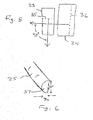
- Figs. 2-4 show an exemplary hearing device 20 according to embodiments of the invention.
- Hearing device 20 is highly miniaturized for placement entirely in the bony part 12 of the ear canal 10 for extended wear therein. Since there is minimal debris and no canal deformations in the bony part 12 of the ear canal, hearing device 20 can remain functional and stable in the ear canal for longer periods exceeding 2 months.
- Hearing device 20 is highly energy efficient and can thereby eliminate resorting to daily insertion and removal as is the case with conventional daily wear devices.
- a novel approach is taken in embodiments of the present invention to minimize the length of the hearing device. The approach comprises placing the speaker (receiver) 24 axially in parallel to the microphone 23 within a lateral assembly 22.
- Lateral assembly 22 can be adapted to face away from tympanic membrane 18 when hearing device 20 is placed in the ear canal. Sound may be conducted from the speaker 24 medially to the residual volume 19 between a medial end 29 and the tympanic membrane 18 via sound conduit 25. Medial end 29 can be adapted to face tympanic membrane 18 when hearing device 20 is placed in the ear canal.
- the microphone and receiver can be combined within a unitary electronic assembly without resorting to axial separation. Feedback mitigation can be accomplished by orthogonal placement of the diaphragms of the transducers (the speaker and the microphone) as will be described further below.
- the term “lateral” refers to the direction facing away from tympanic membrane 18 and the term “medial” refers to the direction facing toward tympanic membrane 18.
- the lateral assembly 22 also comprises a flexible circuit 28.
- Flexible circuit 28 contains an integrated circuit or amplifier 26 and other discrete components 39.
- a battery 27 can be medially positioned with a low profile sound conduit 25 preferably having a half-pipe (D-shaped) cross section for carrying sound from receiver 24 to the medial end 29 of the hearing device 20 via sound opening 37 as shown in Fig. 6 .
- the lateral combined assembly 22 can be connected to the battery assembly 37 preferably without articulation but optionally with articulation if so desired.
- Lateral acoustic seal 30 and medial seal 32 may secure the device 20 in the bony ear canal and can provide acoustic attenuation to mitigate occurrence of feedback.
- a basic principle of the invention is the precise orthogonal placement of the speaker diaphragm 36 with respect to microphone diaphragm 35 as shown in Figs. 3 and 5 .
- This orthogonal arrangement of the diaphragms can result in minimizing the sensitivity of the microphone to vibrations produced by the receiver.
- the cross coupling is directly proportional to the cosine of the angle between the planes of the diaphragms with 90° degrees resulting theoretically in zero cross coupling. Since vibration vectors may not be exactly perpendicular across all audio frequencies, due to the complex patterns of vibrations and diaphragm deformations at a particular frequency, the optimal placement of the microphone with respect to the speaker may be slightly off 90° degrees to obtain minimal cross coupling for feedback control.
- the exact angle of placement may be derived by mathematically by methods such as finite-element-analysis (FEA) or empirically derived by experimentation for particular models of a transducer pair.
- FFA finite-element-analysis
- the desired diaphragm arrangement may be expected to be at or be close to 90°, resulting in a microphone being responsive primarily to incident sound waves and relatively insensitive to vibrations from the speaker even though it is adjacently positioned.
- the orthogonal placement of transducer diaphragms can eliminate the conventional requirement of providing spatial separation, particularly along the axial dimension of the hearing device.
- Fig. 4 shows a viscoelastic damper 21 which may be preferably included to separate the microphone 23 and the adjacently positioned receiver 24.
- a low vibration speaker incorporating dual diaphragm (not shown) may be used to minimize speaker vibrations.
- a dual diaphragm receiver relies on two parallel diaphragms arranged to move in opposite directions to cancel out case vibration effects while boosting the acoustic output.
- the microphone 23 can be cylindrical type such as FG series (manufactured by Knowles Electronics) or series 151 made by Tibbetts Industries, incorporating ultra low power preamp within.
- the receiver 24 can be an ultra miniature type such as an FH or FK series model manufactured by Knowles Electronics, or Series 2600 manufactured by Sonion. Incorporating the receiver and the microphone in a single case can be advantageous and is within the scope of the invention having orthogonal diaphragms for reduced vibration sensitivity.
- Fig. 2 shows placement of the hearing device 20 in the ear canal substantially in the bony area and having a length of no more than 12 mm.
- Hearing device 20 is thus shorter than prior hearing device designs which have axial separation of the microphone and receiver. Because the device is entirely in the bony part, canal deformations in the cartilaginous area 11 do not impact the device directly.
- Another advantage may be the use of the tapered oval battery 27 to lead the device into the ear canal, thus enabling a more comfortable insertion of the hearing device.
- the use of a tapered oval battery 27 may be particularly useful in canals, which are narrow, highly contoured or with severe bends.
- An oval battery perimeter can mimic the oval cross section of the ear canal and can lead to improved fit and maximum volumetric energy efficiency, compared to the typical button-cell used in conventional hearing aids.
- a handle 31 in the form of a removal cord may be provided for facilitating insertion or removal of the hearing device.
- the desired length of 12 mm of less refers to the two rigid edges of the overall assembly and does not necessarily include the removal cord, which can be made flexible and non-obtrusive.
- Fig. 6 shows the cross sectional view of the sound conduction tube 25 having a D-shaped cross section with long diameter D L and a short diameter D S for reducing the profile of the hearing device when inserted in the ear canal.
- the inside long diameter may be preferably less than 2.5 mm and short inside diameter preferably 1 mm or less.
- the extended wear canal hearing device of the present invention is preferably disposable and worn for at least 2 months. After depletion of the battery or end of life due to contamination, the hearing device can be disposed of and replaced with a new device if so desired.
- the most medial surface of the device may be placed preferably approximately 3 mm from the eardrum and typically in the range of 2-5 mm from the eardrum. Due to exceptional proximity to the eardrum of wearer, a physician or a hearing professional is preferably relied on for inserting the device to ensure safe placement and prevent inadvertent damage to the eardrum or the ear canal. To maximize the longevity of the disposable hearing device, all components within may be encapsulated and proofed to withstand water and debris present in the ear canal.
- the microphone and the speaker are adjacently positioned in a medial assembly medial to the battery.
- This example can utilize the same principle of providing orthogonal diaphragms for the transducers but in a medial assembly instead of a lateral assembly as disclosed above.
- the resulting device can be 12 mm or less for fitting exclusively in the bony part of the ear canal for most individuals.
Claims (7)
- Dispositif auditif à port prolongé destiné à être placé entièrement dans la partie osseuse (12) du conduit auditif (10), le dispositif auditif (20) comprenant un ensemble transducteur (22) comprenant :a. un haut-parleur (24) ayant un diaphragme de haut-parleur (36) pour produire des vibrations audibles ; etb. un microphone (23) adjacent audit haut-parleur, le microphone ayant un diaphragme de microphone (35),caractérisé en ce que le diaphragme de microphone est orienté sensiblement orthogonalement au diaphragme de haut-parleur, le microphone et le haut-parleur étant disposés au niveau d'une extrémité latérale du dispositif auditif opposée à la membrane tympanique (18), et une longueur dudit dispositif auditif à port prolongé étant inférieure ou égale à 12 mm grâce au co-placement parallèle dudit microphone et dudit haut-parleur à l'intérieur d'un ensemble combiné dudit haut-parleur et dudit microphone, mesurée de l'extrémité latérale du dispositif auditif à l'extrémité médiale du dispositif auditif lorsque le dispositif auditif est placé entièrement dans le conduit auditif pour un port prolongé, ce qui permet au dispositif auditif d'être logé exclusivement dans la partie osseuse du conduit auditif et de ne pas être soumis à la mobilité et aux déformations présentes dans la partie cartilagineuse (11) du conduit auditif lorsque ledit dispositif auditif est placé dans le conduit auditif pour un port prolongé à l'intérieur.
- Dispositif auditif selon la revendication 1, ledit dispositif auditif (20) comprenant une batterie (27) qui a une section transversale ovale et une extrémité médiale conique.
- Dispositif auditif selon la revendication 1, une sortie acoustique dudit haut-parleur (24) étant couplée acoustiquement à un volume résiduel (19) entre une extrémité médiale (29) du dispositif auditif (20) tournée vers la membrane tympanique (18) et la membrane tympanique par l'intermédiaire d'un canal conducteur du son (25) étroit.
- Dispositif auditif selon la revendication 3, ledit canal conducteur du son comprenant un tube (25) ayant une section transversale en forme de D ayant un diamètre intérieur court de 1 mm ou moins.
- Dispositif auditif selon la revendication 1, ledit haut-parleur (24) comprenant un diaphragme double pour réduire les vibrations du boîtier de haut-parleur.
- Dispositif auditif selon la revendication 1, les composants à l'intérieur du dispositif auditif (20) étant encapsulés et éprouvés pour résister à l'eau et aux débris présents dans le conduit auditif (10).
- Dispositif auditif selon la revendication 1, comprenant en outre un amortisseur viscoélastique (21) disposé entre ledit microphone (23) et ledit haut-parleur (24), l'amortisseur viscoélastique étant conçu pour réduire le couplage vibratoire entre ceux-ci.
Applications Claiming Priority (2)
| Application Number | Priority Date | Filing Date | Title |
|---|---|---|---|
| US95575507P | 2007-08-14 | 2007-08-14 | |
| PCT/US2008/073065 WO2009023738A2 (fr) | 2007-08-14 | 2008-08-13 | Ensemble microphone et récepteur combiné pour des dispositifs auditifs de canal à port étendu |
Publications (4)
| Publication Number | Publication Date |
|---|---|
| EP2177046A2 EP2177046A2 (fr) | 2010-04-21 |
| EP2177046A4 EP2177046A4 (fr) | 2014-01-08 |
| EP2177046B1 EP2177046B1 (fr) | 2017-03-15 |
| EP2177046B2 true EP2177046B2 (fr) | 2020-05-27 |
Family
ID=40351471
Family Applications (1)
| Application Number | Title | Priority Date | Filing Date |
|---|---|---|---|
| EP08797823.5A Not-in-force EP2177046B2 (fr) | 2007-08-14 | 2008-08-13 | Ensemble microphone et récepteur combiné pour des dispositifs auditifs de canal à port étendu |
Country Status (4)
| Country | Link |
|---|---|
| US (1) | US9071914B2 (fr) |
| EP (1) | EP2177046B2 (fr) |
| CN (1) | CN101836463A (fr) |
| WO (1) | WO2009023738A2 (fr) |
Families Citing this family (41)
| Publication number | Priority date | Publication date | Assignee | Title |
|---|---|---|---|---|
| US8526641B2 (en) * | 2008-03-31 | 2013-09-03 | Cochlear Limited | Customizable mass arrangements for bone conduction devices |
| EP2107828B1 (fr) * | 2008-04-02 | 2016-06-29 | Sonion Nederland B.V. | Ensemble comportant un émetteur de son et deux détecteurs de son |
| US9826322B2 (en) | 2009-07-22 | 2017-11-21 | Eargo, Inc. | Adjustable securing mechanism |
| US10097936B2 (en) | 2009-07-22 | 2018-10-09 | Eargo, Inc. | Adjustable securing mechanism |
| US10334370B2 (en) | 2009-07-25 | 2019-06-25 | Eargo, Inc. | Apparatus, system and method for reducing acoustic feedback interference signals |
| EP2457387B1 (fr) | 2009-07-22 | 2018-09-12 | Eargo, Inc. | Prothèse auditive pour conduit auditif ouvert |
| US10284977B2 (en) | 2009-07-25 | 2019-05-07 | Eargo, Inc. | Adjustable securing mechanism |
| KR101612851B1 (ko) * | 2010-02-01 | 2016-04-18 | 삼성전자주식회사 | 초소형 보청기 |
| WO2011116246A1 (fr) | 2010-03-19 | 2011-09-22 | Advanced Bionics Ag | Enveloppes étanches pour éléments acoustiques et appareil comprenant une telle enveloppe |
| DK2393308T3 (da) * | 2010-06-07 | 2020-01-20 | Oticon As | Høreapparat, der omfatter et foldet substrat |
| US9002049B2 (en) * | 2010-10-08 | 2015-04-07 | Starkey Laboratories, Inc. | Housing for a standard fit hearing assistance device |
| US9132270B2 (en) | 2011-01-18 | 2015-09-15 | Advanced Bionics Ag | Moisture resistant headpieces and implantable cochlear stimulation systems including the same |
| NL2007136C2 (nl) * | 2011-07-18 | 2013-01-21 | Exsilent Res Bv | Luisterondersteuningsinrichting, in het bijzonder een hoortoestel, alsmede een samendrukbare huls voor toepassing daarmee. |
| US8682016B2 (en) | 2011-11-23 | 2014-03-25 | Insound Medical, Inc. | Canal hearing devices and batteries for use with same |
| US8761423B2 (en) | 2011-11-23 | 2014-06-24 | Insound Medical, Inc. | Canal hearing devices and batteries for use with same |
| US8808906B2 (en) | 2011-11-23 | 2014-08-19 | Insound Medical, Inc. | Canal hearing devices and batteries for use with same |
| EP2898705B1 (fr) | 2012-09-18 | 2017-08-23 | Sonova AG | Appareil auditif cic |
| US10812919B2 (en) | 2013-03-15 | 2020-10-20 | Cochlear Limited | Filtering well-defined feedback from a hard-coupled vibrating transducer |
| EP2785075B1 (fr) * | 2013-03-27 | 2016-05-18 | Oticon Medical A/S | Appareil de mesure permettant de vérifier et d'étalonner des vibrateurs à conduction osseuse |
| WO2014196851A1 (fr) * | 2013-05-20 | 2014-12-11 | Jin Hem Thong | Dispositif intra-auriculaire de communication bidirectionnelle avec interférence réduite |
| US20160094922A1 (en) * | 2014-09-29 | 2016-03-31 | Oticon A/S | Positioned hearing system |
| EP3269153B1 (fr) | 2015-03-09 | 2019-05-22 | Sonova AG | Prothèses auditives intra-canal munies de garnitures d'étanchéité améliorées |
| EP3086573B1 (fr) * | 2015-04-20 | 2022-12-07 | Oticon A/s | Dispositif auditif conçu pour etre place dans le canal auditif d'un utilisateur |
| US10524068B2 (en) | 2016-01-07 | 2019-12-31 | Sonova Ag | Hearing assistance device transducers and hearing assistance devices with same |
| US10582320B2 (en) * | 2016-03-10 | 2020-03-03 | Sonova Ag | Canal hearing device sizer apparatus, systems and methods |
| EP3437330B1 (fr) | 2016-04-01 | 2021-06-09 | Widex A/S | Suspension d'un haut-parleur dans un appareil auditif |
| US10897676B2 (en) | 2016-06-17 | 2021-01-19 | Sonova Ag | Customized device for insertion of a deep-cana hearing aid and a method for manufacturing and using such an insertion device |
| MX2019000303A (es) * | 2016-07-07 | 2019-10-15 | Meyer Sound Laboratories Incorporated | Correcion de magnitud y fase de un dispositivo auditivo. |
| US11206499B2 (en) * | 2016-08-18 | 2021-12-21 | Qualcomm Incorporated | Hearable device comprising integrated device and wireless functionality |
| US10678502B2 (en) * | 2016-10-20 | 2020-06-09 | Qualcomm Incorporated | Systems and methods for in-ear control of remote devices |
| US9961458B1 (en) | 2016-10-27 | 2018-05-01 | Intricon Corporation | Hearing aid sleeve |
| NL2018617B1 (en) | 2017-03-30 | 2018-10-10 | Axign B V | Intra ear canal hearing aid |
| US11277698B2 (en) | 2017-11-24 | 2022-03-15 | Sonova Ag | Canal hearing devices with improved seals |
| EP3531720B1 (fr) * | 2018-02-26 | 2021-09-15 | Sonion Nederland B.V. | Assemblage d'un récepteur et d'un microphone |
| US10701497B2 (en) | 2018-09-24 | 2020-06-30 | Sonova Ag | Hearing device seal modules, modular hearing devices including the same and associated methods |
| US11570561B2 (en) * | 2018-12-07 | 2023-01-31 | Falcom A/S | Hearing devices and methods of making the same |
| US11324456B2 (en) * | 2019-09-23 | 2022-05-10 | Sonova Ag | Deep ear sensor for reducing noise from movement and environment |
| DK202070803A1 (en) * | 2020-11-30 | 2022-06-16 | Gn Hearing As | Hearing device earpiece with tilted microphone/receiver |
| US11336982B1 (en) | 2020-12-26 | 2022-05-17 | Sonova Ag | Hearing device seal modules, modular hearing devices including the same and associated methods |
| US11930319B2 (en) * | 2021-01-22 | 2024-03-12 | Rishi Sai Sadanandan | Underwater ear pod system |
| US11678126B1 (en) | 2021-12-09 | 2023-06-13 | Sonova Ag | Hearing device seal modules, modular hearing devices including the same and associated methods |
Citations (21)
| Publication number | Priority date | Publication date | Assignee | Title |
|---|---|---|---|---|
| US2634337A (en) † | 1947-12-05 | 1953-04-07 | Reginald B Bland | Combined microphone and receiver for audiphones |
| US2967913A (en) † | 1956-04-26 | 1961-01-10 | Aubert Maurice | Electronic intensifying ear-drum |
| US4109116A (en) † | 1977-07-19 | 1978-08-22 | Victoreen John A | Hearing aid receiver with plural transducers |
| US4447677A (en) † | 1981-04-20 | 1984-05-08 | Sony Corporation | Hearing aid |
| US4969534A (en) † | 1988-08-08 | 1990-11-13 | Minnesota Mining And Manufacturing Company | Hearing aid employing a viscoelastic material to adhere components to the casing |
| WO2000032009A2 (fr) † | 1998-11-25 | 2000-06-02 | Insonus Medical, Inc. | Appareil auditif semi-permanent dispose dans le conduit auditif |
| WO2000076271A1 (fr) † | 1999-06-08 | 2000-12-14 | Insonus Medical, Inc. | Dispositif de correction auditive a installation dans le conduit, pour un port prolonge |
| US6208741B1 (en) † | 1998-11-12 | 2001-03-27 | Insonus Medical, Inc. | Battery enclosure for canal hearing devices |
| US6212283B1 (en) † | 1997-09-03 | 2001-04-03 | Decibel Instruments, Inc. | Articulation assembly for intracanal hearing devices |
| WO2001043499A1 (fr) † | 1999-12-10 | 2001-06-14 | Sonic Innovations, Inc. | Extremite conformee destine a un dispositif d'audition a aerateur integre et cordon de localisation |
| WO2002015635A2 (fr) † | 2000-08-07 | 2002-02-21 | Insonus Medical, Inc. | Ensemble de pile ovale allonge pour des appareils auditifs intra-canal |
| US20020025055A1 (en) † | 2000-06-29 | 2002-02-28 | Stonikas Paul R. | Compressible hearing aid |
| WO2004010734A1 (fr) † | 2002-07-18 | 2004-01-29 | Insound Medical, Inc. | Dispositif auditif intracanal a insert tubulaire |
| US20040165742A1 (en) † | 1999-04-29 | 2004-08-26 | Insound Medical, Inc. | Canal hearing device with tubular insert |
| US20050074138A1 (en) † | 2003-06-30 | 2005-04-07 | Siemens Hearing Instruments Inc. | Feedback reducing receiver mount and assembly |
| WO2005076991A2 (fr) † | 2004-02-05 | 2005-08-25 | Insound Medical, Inc. | Appareil auditif de port prolonge comportant une cavite commune microphone-accumulateur |
| WO2005079373A2 (fr) † | 2004-02-13 | 2005-09-01 | Insound Medical, Inc. | Capsule perforees pour appareil auditif |
| WO2005115053A1 (fr) † | 2004-05-14 | 2005-12-01 | Sonion Nederland B.V. | Transducteur electroacoustique a membrane double |
| EP1629808A1 (fr) † | 2004-08-25 | 2006-03-01 | Phonak Ag | Bouchon d'oreille et son procédé de fabrication |
| EP1062840B1 (fr) † | 1997-12-18 | 2006-03-29 | Softear Technologies, L.L.C. | Appareil et procede destines a une prothese auditive souple/solide |
| US20070036379A1 (en) † | 2005-08-12 | 2007-02-15 | Insound Medical, Inc. | Flexible joint for extended wear hearing device |
Family Cites Families (83)
| Publication number | Priority date | Publication date | Assignee | Title |
|---|---|---|---|---|
| US3061689A (en) * | 1957-05-27 | 1962-10-30 | Beltone Hearing Aid Company | Hearing aid |
| USRE26258E (en) | 1964-04-02 | 1967-08-29 | In-the-ear hearing aid | |
| US3414685A (en) * | 1965-09-23 | 1968-12-03 | Dahlberg Electronics | In-the-ear hearing aid |
| US3527901A (en) * | 1967-03-28 | 1970-09-08 | Dahlberg Electronics | Hearing aid having resilient housing |
| US3594514A (en) * | 1970-01-02 | 1971-07-20 | Medtronic Inc | Hearing aid with piezoelectric ceramic element |
| US3865998A (en) * | 1970-12-02 | 1975-02-11 | Beltone Electronics Corp | Ear seal |
| US3783201A (en) * | 1970-12-02 | 1974-01-01 | Beltone Electronics Corp | Miniature hearing aid structure |
| US3764748A (en) * | 1972-05-19 | 1973-10-09 | J Branch | Implanted hearing aids |
| GB1440724A (en) * | 1972-07-18 | 1976-06-23 | Fredrickson J M | Implantable electromagnetic hearing aid |
| US3882285A (en) * | 1973-10-09 | 1975-05-06 | Vicon Instr Company | Implantable hearing aid and method of improving hearing |
| FR2497937B1 (fr) * | 1981-01-13 | 1986-03-07 | Stein Industrie | Dispositif d'echange de chaleur a faisceau de tubes avec lyres de dilatation soustraites aux vibrations |
| US4442917A (en) * | 1981-01-19 | 1984-04-17 | Johnson Rubein V | Vented acoustic ear mold for hearing aids |
| US4539440A (en) * | 1983-05-16 | 1985-09-03 | Michael Sciarra | In-canal hearing aid |
| DE8318579U1 (de) * | 1983-06-27 | 1983-11-17 | Siemens AG, 1000 Berlin und 8000 München | Hörgerät |
| DE3336266A1 (de) * | 1983-10-05 | 1985-04-18 | Siemens AG, 1000 Berlin und 8000 München | Hoergeraet |
| US4628907A (en) * | 1984-03-22 | 1986-12-16 | Epley John M | Direct contact hearing aid apparatus |
| US4756312A (en) * | 1984-03-22 | 1988-07-12 | Advanced Hearing Technology, Inc. | Magnetic attachment device for insertion and removal of hearing aid |
| AT380762B (de) * | 1984-08-06 | 1986-07-10 | Viennatone Gmbh | Hoergeraet |
| US5015225A (en) * | 1985-05-22 | 1991-05-14 | Xomed, Inc. | Implantable electromagnetic middle-ear bone-conduction hearing aid device |
| US4606329A (en) * | 1985-05-22 | 1986-08-19 | Xomed, Inc. | Implantable electromagnetic middle-ear bone-conduction hearing aid device |
| US4776322A (en) * | 1985-05-22 | 1988-10-11 | Xomed, Inc. | Implantable electromagnetic middle-ear bone-conduction hearing aid device |
| US4817607A (en) * | 1986-03-07 | 1989-04-04 | Richards Medical Company | Magnetic ossicular replacement prosthesis |
| US4840178A (en) * | 1986-03-07 | 1989-06-20 | Richards Metal Company | Magnet for installation in the middle ear |
| US4870688A (en) * | 1986-05-27 | 1989-09-26 | Barry Voroba | Mass production auditory canal hearing aid |
| US4830139A (en) * | 1986-08-04 | 1989-05-16 | Cirillo Evelyn J | Hearing aid holding means and method of using same |
| US5002151A (en) * | 1986-12-05 | 1991-03-26 | Minnesota Mining And Manufacturing Company | Ear piece having disposable, compressible polymeric foam sleeve |
| US4880076A (en) * | 1986-12-05 | 1989-11-14 | Minnesota Mining And Manufacturing Company | Hearing aid ear piece having disposable compressible polymeric foam sleeve |
| US5201008A (en) * | 1987-01-27 | 1993-04-06 | Unitron Industries Ltd. | Modular hearing aid with lid hinged to faceplate |
| US5031219A (en) * | 1988-09-15 | 1991-07-09 | Epic Corporation | Apparatus and method for conveying amplified sound to the ear |
| US5201007A (en) * | 1988-09-15 | 1993-04-06 | Epic Corporation | Apparatus and method for conveying amplified sound to ear |
| NL8802355A (nl) * | 1988-09-26 | 1990-04-17 | Philips Nv | In-het-oor hoorapparaat. |
| US5015224A (en) * | 1988-10-17 | 1991-05-14 | Maniglia Anthony J | Partially implantable hearing aid device |
| US4957478A (en) * | 1988-10-17 | 1990-09-18 | Maniglia Anthony J | Partially implantable hearing aid device |
| US5220918A (en) * | 1988-11-16 | 1993-06-22 | Smith & Nephew Richards, Inc. | Trans-tympanic connector for magnetic induction hearing aid |
| US5185802A (en) * | 1990-04-12 | 1993-02-09 | Beltone Electronics Corporation | Modular hearing aid system |
| US5259032A (en) * | 1990-11-07 | 1993-11-02 | Resound Corporation | contact transducer assembly for hearing devices |
| DE69233156T2 (de) * | 1991-01-17 | 2004-07-08 | Adelman, Roger A. | Verbessertes hörgerät |
| EP0578752B1 (fr) * | 1991-04-01 | 1997-09-03 | Resound Corporation | Procede de communication discrete a commande electromagnetique a distance |
| US5195139A (en) * | 1991-05-15 | 1993-03-16 | Ensoniq Corporation | Hearing aid |
| US5282858A (en) * | 1991-06-17 | 1994-02-01 | American Cyanamid Company | Hermetically sealed implantable transducer |
| US5163957A (en) * | 1991-09-10 | 1992-11-17 | Smith & Nephew Richards, Inc. | Ossicular prosthesis for mounting magnet |
| US5682020A (en) * | 1991-12-09 | 1997-10-28 | Oliveira; Robert J. | Sealing of hearing aid to ear canal |
| US5220612A (en) * | 1991-12-20 | 1993-06-15 | Tibbetts Industries, Inc. | Non-occludable transducers for in-the-ear applications |
| US5338287A (en) * | 1991-12-23 | 1994-08-16 | Miller Gale W | Electromagnetic induction hearing aid device |
| US5531787A (en) * | 1993-01-25 | 1996-07-02 | Lesinski; S. George | Implantable auditory system with micromachined microsensor and microactuator |
| EP0629101B1 (fr) * | 1993-06-11 | 2001-09-05 | Ascom Audiosys Ag | Prothèse auditive à porter dans l'oreille et procédé pour sa fabrication |
| US5624376A (en) * | 1993-07-01 | 1997-04-29 | Symphonix Devices, Inc. | Implantable and external hearing systems having a floating mass transducer |
| US5554096A (en) * | 1993-07-01 | 1996-09-10 | Symphonix | Implantable electromagnetic hearing transducer |
| US5456654A (en) * | 1993-07-01 | 1995-10-10 | Ball; Geoffrey R. | Implantable magnetic hearing aid transducer |
| US5430801A (en) * | 1993-12-14 | 1995-07-04 | Hill; Frank C. | Hearing aid |
| EP0704143B1 (fr) * | 1994-04-08 | 2000-09-13 | Beltone Netherlands B.V. | Prothese auditive interne a obturation souple |
| US5659621A (en) * | 1994-08-31 | 1997-08-19 | Argosy Electronics, Inc. | Magnetically controllable hearing aid |
| US5572594A (en) * | 1994-09-27 | 1996-11-05 | Devoe; Lambert | Ear canal device holder |
| US5701348A (en) * | 1994-12-29 | 1997-12-23 | Decibel Instruments, Inc. | Articulated hearing device |
| DE19504478C2 (de) * | 1995-02-10 | 1996-12-19 | Siemens Audiologische Technik | Gehörgangseinsatz für Hörhilfen |
| US5949895A (en) * | 1995-09-07 | 1999-09-07 | Symphonix Devices, Inc. | Disposable audio processor for use with implanted hearing devices |
| KR19990082641A (ko) * | 1996-02-15 | 1999-11-25 | 알만드 피. 뉴커만스 | 개량된 생체교합적인 트랜스듀서 |
| US5724431A (en) * | 1996-02-26 | 1998-03-03 | Siemens Hearing Instruments, Inc. | Zinc-air dry cell holder and hearing aid that uses it |
| US6473511B1 (en) * | 1996-03-14 | 2002-10-29 | Sarnoff Corporation | Disposable hearing aid with integral power source |
| EP0901743A1 (fr) * | 1996-03-26 | 1999-03-17 | Sarnoff Corporation | Ensemble batterie et circuit |
| DE19618961B4 (de) * | 1996-05-10 | 2004-09-16 | Phonak Ag | Gerät zur elektromechanischen Stimulation und Prüfung des Gehörs |
| US5825896A (en) * | 1996-06-26 | 1998-10-20 | David Sarnoff Research Center Inc. | Hinged hearing aid |
| US6595796B1 (en) * | 1997-03-31 | 2003-07-22 | The Whitaker Corporation | Flexible film circuit connector |
| JPH1169499A (ja) * | 1997-07-18 | 1999-03-09 | Koninkl Philips Electron Nv | 補聴器、リモート制御装置及びシステム |
| US6346811B1 (en) * | 1997-10-20 | 2002-02-12 | Wolff Controls Corp. | Methods for mounting a sensor and signal conditioner to form sensing apparatus having enhanced sensing capabilities and reduced size |
| US5982908A (en) * | 1997-12-22 | 1999-11-09 | Bauman; Natan | Ear wax collection device for a hearing aid |
| US6137889A (en) * | 1998-05-27 | 2000-10-24 | Insonus Medical, Inc. | Direct tympanic membrane excitation via vibrationally conductive assembly |
| US7664282B2 (en) * | 1998-11-25 | 2010-02-16 | Insound Medical, Inc. | Sealing retainer for extended wear hearing devices |
| US7580537B2 (en) * | 1998-11-25 | 2009-08-25 | Insound Medical, Inc. | Sealing retainer for extended wear hearing devices |
| WO2000041432A2 (fr) * | 1999-01-07 | 2000-07-13 | Sarnoff Corporation | Appareil de correction auditive dote d'un microphone a grande membrane et d'une carte a circuit imprime |
| US6359993B2 (en) * | 1999-01-15 | 2002-03-19 | Sonic Innovations | Conformal tip for a hearing aid with integrated vent and retrieval cord |
| US6658126B1 (en) * | 1999-04-07 | 2003-12-02 | Ericsson Inc. | Hearing aid compatible piezoelectric speaker |
| US6094492A (en) * | 1999-05-10 | 2000-07-25 | Boesen; Peter V. | Bone conduction voice transmission apparatus and system |
| US6648813B2 (en) * | 2000-06-17 | 2003-11-18 | Alfred E. Mann Foundation For Scientific Research | Hearing aid system including speaker implanted in middle ear |
| US6516074B1 (en) * | 2000-10-19 | 2003-02-04 | Sonic Innovations, Inc. | Hearing device with integrated battery compartment and switch |
| US6620110B2 (en) * | 2000-12-29 | 2003-09-16 | Phonak Ag | Hearing aid implant mounted in the ear and hearing aid implant |
| US6643378B2 (en) * | 2001-03-02 | 2003-11-04 | Daniel R. Schumaier | Bone conduction hearing aid |
| US20060098833A1 (en) * | 2004-05-28 | 2006-05-11 | Juneau Roger P | Self forming in-the-ear hearing aid |
| US7263195B2 (en) * | 2004-12-22 | 2007-08-28 | Ultimate Ears, Llc | In-ear monitor with shaped dual bore |
| EP1684544B1 (fr) * | 2005-01-10 | 2011-03-16 | Sonion Nederland B.V. | Montage d'un transducteur électroacoustique dans des coques de dispositifs personnels de communication |
| US7844065B2 (en) * | 2005-01-14 | 2010-11-30 | Phonak Ag | Hearing instrument |
| US20080205679A1 (en) * | 2005-07-18 | 2008-08-28 | Darbut Alexander L | In-Ear Auditory Device and Methods of Using Same |
| US7983433B2 (en) * | 2005-11-08 | 2011-07-19 | Think-A-Move, Ltd. | Earset assembly |
-
2008
- 2008-08-13 CN CN200880103248A patent/CN101836463A/zh active Pending
- 2008-08-13 EP EP08797823.5A patent/EP2177046B2/fr not_active Not-in-force
- 2008-08-13 WO PCT/US2008/073065 patent/WO2009023738A2/fr active Application Filing
- 2008-08-13 US US12/191,136 patent/US9071914B2/en active Active
Patent Citations (22)
| Publication number | Priority date | Publication date | Assignee | Title |
|---|---|---|---|---|
| US2634337A (en) † | 1947-12-05 | 1953-04-07 | Reginald B Bland | Combined microphone and receiver for audiphones |
| US2967913A (en) † | 1956-04-26 | 1961-01-10 | Aubert Maurice | Electronic intensifying ear-drum |
| US4109116A (en) † | 1977-07-19 | 1978-08-22 | Victoreen John A | Hearing aid receiver with plural transducers |
| US4447677A (en) † | 1981-04-20 | 1984-05-08 | Sony Corporation | Hearing aid |
| US4969534A (en) † | 1988-08-08 | 1990-11-13 | Minnesota Mining And Manufacturing Company | Hearing aid employing a viscoelastic material to adhere components to the casing |
| US6212283B1 (en) † | 1997-09-03 | 2001-04-03 | Decibel Instruments, Inc. | Articulation assembly for intracanal hearing devices |
| EP1062840B1 (fr) † | 1997-12-18 | 2006-03-29 | Softear Technologies, L.L.C. | Appareil et procede destines a une prothese auditive souple/solide |
| US6208741B1 (en) † | 1998-11-12 | 2001-03-27 | Insonus Medical, Inc. | Battery enclosure for canal hearing devices |
| WO2000032009A2 (fr) † | 1998-11-25 | 2000-06-02 | Insonus Medical, Inc. | Appareil auditif semi-permanent dispose dans le conduit auditif |
| US20040165742A1 (en) † | 1999-04-29 | 2004-08-26 | Insound Medical, Inc. | Canal hearing device with tubular insert |
| WO2000076271A1 (fr) † | 1999-06-08 | 2000-12-14 | Insonus Medical, Inc. | Dispositif de correction auditive a installation dans le conduit, pour un port prolonge |
| US20020085728A1 (en) † | 1999-06-08 | 2002-07-04 | Insonus Medical, Inc. | Disposable extended wear canal hearing device |
| WO2001043499A1 (fr) † | 1999-12-10 | 2001-06-14 | Sonic Innovations, Inc. | Extremite conformee destine a un dispositif d'audition a aerateur integre et cordon de localisation |
| US20020025055A1 (en) † | 2000-06-29 | 2002-02-28 | Stonikas Paul R. | Compressible hearing aid |
| WO2002015635A2 (fr) † | 2000-08-07 | 2002-02-21 | Insonus Medical, Inc. | Ensemble de pile ovale allonge pour des appareils auditifs intra-canal |
| WO2004010734A1 (fr) † | 2002-07-18 | 2004-01-29 | Insound Medical, Inc. | Dispositif auditif intracanal a insert tubulaire |
| US20050074138A1 (en) † | 2003-06-30 | 2005-04-07 | Siemens Hearing Instruments Inc. | Feedback reducing receiver mount and assembly |
| WO2005076991A2 (fr) † | 2004-02-05 | 2005-08-25 | Insound Medical, Inc. | Appareil auditif de port prolonge comportant une cavite commune microphone-accumulateur |
| WO2005079373A2 (fr) † | 2004-02-13 | 2005-09-01 | Insound Medical, Inc. | Capsule perforees pour appareil auditif |
| WO2005115053A1 (fr) † | 2004-05-14 | 2005-12-01 | Sonion Nederland B.V. | Transducteur electroacoustique a membrane double |
| EP1629808A1 (fr) † | 2004-08-25 | 2006-03-01 | Phonak Ag | Bouchon d'oreille et son procédé de fabrication |
| US20070036379A1 (en) † | 2005-08-12 | 2007-02-15 | Insound Medical, Inc. | Flexible joint for extended wear hearing device |
Also Published As
| Publication number | Publication date |
|---|---|
| WO2009023738A2 (fr) | 2009-02-19 |
| US20090074220A1 (en) | 2009-03-19 |
| EP2177046A2 (fr) | 2010-04-21 |
| WO2009023738A3 (fr) | 2010-01-14 |
| CN101836463A (zh) | 2010-09-15 |
| EP2177046B1 (fr) | 2017-03-15 |
| EP2177046A4 (fr) | 2014-01-08 |
| US9071914B2 (en) | 2015-06-30 |
Similar Documents
| Publication | Publication Date | Title |
|---|---|---|
| EP2177046B2 (fr) | Ensemble microphone et récepteur combiné pour des dispositifs auditifs de canal à port étendu | |
| JP4708645B2 (ja) | 長期装着式耳管型補聴器 | |
| US8885858B2 (en) | Modular hearing instrument | |
| US8340335B1 (en) | Hearing device with semipermanent canal receiver module | |
| JP4384360B2 (ja) | 半永久的に装着可能なカナル型聴覚装置 | |
| US6359993B2 (en) | Conformal tip for a hearing aid with integrated vent and retrieval cord | |
| RU2191485C2 (ru) | Слуховой аппарат шарнирного типа | |
| US8437489B2 (en) | Hearing instrument | |
| JP6144865B2 (ja) | プリント回路基板で形成された壁を有する聴覚補助装置 | |
| US20120237068A1 (en) | Soft Concha Ring Behind-The-Ear Hearing Aid | |
| WO2004010734A1 (fr) | Dispositif auditif intracanal a insert tubulaire | |
| JP6169778B2 (ja) | 耳掛け補聴器 | |
| WO2000042815A1 (fr) | Embout conforme pour appareil de correction auditive | |
| KR101777182B1 (ko) | 쉘 및 실리콘 슬리브 팁이 상호 탈부착 용이하며, 착용시 울림현상이 없는 보청기 | |
| CA2209068C (fr) | Dispositif de correction auditive articule | |
| WO2001043500A1 (fr) | Embout conforme pour un appareil de correction auditive | |
| DK2238773T3 (en) | Hearing aid with a wall formed by a printed circuit board |
Legal Events
| Date | Code | Title | Description |
|---|---|---|---|
| PUAI | Public reference made under article 153(3) epc to a published international application that has entered the european phase |
Free format text: ORIGINAL CODE: 0009012 |
|
| 17P | Request for examination filed |
Effective date: 20100201 |
|
| AK | Designated contracting states |
Kind code of ref document: A2 Designated state(s): AT BE BG CH CY CZ DE DK EE ES FI FR GB GR HR HU IE IS IT LI LT LU LV MC MT NL NO PL PT RO SE SI SK TR |
|
| AX | Request for extension of the european patent |
Extension state: AL BA MK RS |
|
| DAX | Request for extension of the european patent (deleted) | ||
| A4 | Supplementary search report drawn up and despatched |
Effective date: 20131206 |
|
| RIC1 | Information provided on ipc code assigned before grant |
Ipc: H04R 25/00 20060101ALI20131202BHEP Ipc: H04R 5/00 20060101AFI20131202BHEP |
|
| REG | Reference to a national code |
Ref country code: DE Ref legal event code: R079 Ref document number: 602008049252 Country of ref document: DE Free format text: PREVIOUS MAIN CLASS: H04R0005000000 Ipc: H04R0025020000 |
|
| GRAP | Despatch of communication of intention to grant a patent |
Free format text: ORIGINAL CODE: EPIDOSNIGR1 |
|
| RIC1 | Information provided on ipc code assigned before grant |
Ipc: H04R 25/02 20060101AFI20160804BHEP Ipc: H04R 25/00 20060101ALI20160804BHEP |
|
| INTG | Intention to grant announced |
Effective date: 20160831 |
|
| GRAJ | Information related to disapproval of communication of intention to grant by the applicant or resumption of examination proceedings by the epo deleted |
Free format text: ORIGINAL CODE: EPIDOSDIGR1 |
|
| GRAS | Grant fee paid |
Free format text: ORIGINAL CODE: EPIDOSNIGR3 |
|
| GRAP | Despatch of communication of intention to grant a patent |
Free format text: ORIGINAL CODE: EPIDOSNIGR1 |
|
| GRAA | (expected) grant |
Free format text: ORIGINAL CODE: 0009210 |
|
| INTC | Intention to grant announced (deleted) | ||
| INTG | Intention to grant announced |
Effective date: 20170202 |
|
| AK | Designated contracting states |
Kind code of ref document: B1 Designated state(s): AT BE BG CH CY CZ DE DK EE ES FI FR GB GR HR HU IE IS IT LI LT LU LV MC MT NL NO PL PT RO SE SI SK TR |
|
| REG | Reference to a national code |
Ref country code: CH Ref legal event code: EP Ref country code: GB Ref legal event code: FG4D |
|
| REG | Reference to a national code |
Ref country code: IE Ref legal event code: FG4D |
|
| REG | Reference to a national code |
Ref country code: AT Ref legal event code: REF Ref document number: 876678 Country of ref document: AT Kind code of ref document: T Effective date: 20170415 |
|
| REG | Reference to a national code |
Ref country code: DE Ref legal event code: R096 Ref document number: 602008049252 Country of ref document: DE |
|
| REG | Reference to a national code |
Ref country code: NL Ref legal event code: MP Effective date: 20170315 |
|
| REG | Reference to a national code |
Ref country code: LT Ref legal event code: MG4D |
|
| PG25 | Lapsed in a contracting state [announced via postgrant information from national office to epo] |
Ref country code: NO Free format text: LAPSE BECAUSE OF FAILURE TO SUBMIT A TRANSLATION OF THE DESCRIPTION OR TO PAY THE FEE WITHIN THE PRESCRIBED TIME-LIMIT Effective date: 20170615 Ref country code: FI Free format text: LAPSE BECAUSE OF FAILURE TO SUBMIT A TRANSLATION OF THE DESCRIPTION OR TO PAY THE FEE WITHIN THE PRESCRIBED TIME-LIMIT Effective date: 20170315 Ref country code: GR Free format text: LAPSE BECAUSE OF FAILURE TO SUBMIT A TRANSLATION OF THE DESCRIPTION OR TO PAY THE FEE WITHIN THE PRESCRIBED TIME-LIMIT Effective date: 20170616 Ref country code: HR Free format text: LAPSE BECAUSE OF FAILURE TO SUBMIT A TRANSLATION OF THE DESCRIPTION OR TO PAY THE FEE WITHIN THE PRESCRIBED TIME-LIMIT Effective date: 20170315 Ref country code: LT Free format text: LAPSE BECAUSE OF FAILURE TO SUBMIT A TRANSLATION OF THE DESCRIPTION OR TO PAY THE FEE WITHIN THE PRESCRIBED TIME-LIMIT Effective date: 20170315 |
|
| REG | Reference to a national code |
Ref country code: AT Ref legal event code: MK05 Ref document number: 876678 Country of ref document: AT Kind code of ref document: T Effective date: 20170315 |
|
| REG | Reference to a national code |
Ref country code: FR Ref legal event code: PLFP Year of fee payment: 10 |
|
| PG25 | Lapsed in a contracting state [announced via postgrant information from national office to epo] |
Ref country code: SE Free format text: LAPSE BECAUSE OF FAILURE TO SUBMIT A TRANSLATION OF THE DESCRIPTION OR TO PAY THE FEE WITHIN THE PRESCRIBED TIME-LIMIT Effective date: 20170315 Ref country code: LV Free format text: LAPSE BECAUSE OF FAILURE TO SUBMIT A TRANSLATION OF THE DESCRIPTION OR TO PAY THE FEE WITHIN THE PRESCRIBED TIME-LIMIT Effective date: 20170315 Ref country code: BG Free format text: LAPSE BECAUSE OF FAILURE TO SUBMIT A TRANSLATION OF THE DESCRIPTION OR TO PAY THE FEE WITHIN THE PRESCRIBED TIME-LIMIT Effective date: 20170615 |
|
| PG25 | Lapsed in a contracting state [announced via postgrant information from national office to epo] |
Ref country code: NL Free format text: LAPSE BECAUSE OF FAILURE TO SUBMIT A TRANSLATION OF THE DESCRIPTION OR TO PAY THE FEE WITHIN THE PRESCRIBED TIME-LIMIT Effective date: 20170315 |
|
| PG25 | Lapsed in a contracting state [announced via postgrant information from national office to epo] |
Ref country code: EE Free format text: LAPSE BECAUSE OF FAILURE TO SUBMIT A TRANSLATION OF THE DESCRIPTION OR TO PAY THE FEE WITHIN THE PRESCRIBED TIME-LIMIT Effective date: 20170315 Ref country code: CZ Free format text: LAPSE BECAUSE OF FAILURE TO SUBMIT A TRANSLATION OF THE DESCRIPTION OR TO PAY THE FEE WITHIN THE PRESCRIBED TIME-LIMIT Effective date: 20170315 Ref country code: RO Free format text: LAPSE BECAUSE OF FAILURE TO SUBMIT A TRANSLATION OF THE DESCRIPTION OR TO PAY THE FEE WITHIN THE PRESCRIBED TIME-LIMIT Effective date: 20170315 Ref country code: SK Free format text: LAPSE BECAUSE OF FAILURE TO SUBMIT A TRANSLATION OF THE DESCRIPTION OR TO PAY THE FEE WITHIN THE PRESCRIBED TIME-LIMIT Effective date: 20170315 Ref country code: IT Free format text: LAPSE BECAUSE OF FAILURE TO SUBMIT A TRANSLATION OF THE DESCRIPTION OR TO PAY THE FEE WITHIN THE PRESCRIBED TIME-LIMIT Effective date: 20170315 Ref country code: AT Free format text: LAPSE BECAUSE OF FAILURE TO SUBMIT A TRANSLATION OF THE DESCRIPTION OR TO PAY THE FEE WITHIN THE PRESCRIBED TIME-LIMIT Effective date: 20170315 Ref country code: ES Free format text: LAPSE BECAUSE OF FAILURE TO SUBMIT A TRANSLATION OF THE DESCRIPTION OR TO PAY THE FEE WITHIN THE PRESCRIBED TIME-LIMIT Effective date: 20170315 |
|
| PG25 | Lapsed in a contracting state [announced via postgrant information from national office to epo] |
Ref country code: PT Free format text: LAPSE BECAUSE OF FAILURE TO SUBMIT A TRANSLATION OF THE DESCRIPTION OR TO PAY THE FEE WITHIN THE PRESCRIBED TIME-LIMIT Effective date: 20170717 Ref country code: PL Free format text: LAPSE BECAUSE OF FAILURE TO SUBMIT A TRANSLATION OF THE DESCRIPTION OR TO PAY THE FEE WITHIN THE PRESCRIBED TIME-LIMIT Effective date: 20170315 Ref country code: IS Free format text: LAPSE BECAUSE OF FAILURE TO SUBMIT A TRANSLATION OF THE DESCRIPTION OR TO PAY THE FEE WITHIN THE PRESCRIBED TIME-LIMIT Effective date: 20170715 |
|
| REG | Reference to a national code |
Ref country code: DE Ref legal event code: R026 Ref document number: 602008049252 Country of ref document: DE |
|
| PLBI | Opposition filed |
Free format text: ORIGINAL CODE: 0009260 |
|
| PLAX | Notice of opposition and request to file observation + time limit sent |
Free format text: ORIGINAL CODE: EPIDOSNOBS2 |
|
| 26 | Opposition filed |
Opponent name: OTICON A/S / WIDEX A/S / GN HEARING A/S Effective date: 20171214 |
|
| PG25 | Lapsed in a contracting state [announced via postgrant information from national office to epo] |
Ref country code: DK Free format text: LAPSE BECAUSE OF FAILURE TO SUBMIT A TRANSLATION OF THE DESCRIPTION OR TO PAY THE FEE WITHIN THE PRESCRIBED TIME-LIMIT Effective date: 20170315 |
|
| PG25 | Lapsed in a contracting state [announced via postgrant information from national office to epo] |
Ref country code: SI Free format text: LAPSE BECAUSE OF FAILURE TO SUBMIT A TRANSLATION OF THE DESCRIPTION OR TO PAY THE FEE WITHIN THE PRESCRIBED TIME-LIMIT Effective date: 20170315 |
|
| REG | Reference to a national code |
Ref country code: CH Ref legal event code: PL |
|
| PG25 | Lapsed in a contracting state [announced via postgrant information from national office to epo] |
Ref country code: MC Free format text: LAPSE BECAUSE OF FAILURE TO SUBMIT A TRANSLATION OF THE DESCRIPTION OR TO PAY THE FEE WITHIN THE PRESCRIBED TIME-LIMIT Effective date: 20170315 |
|
| PG25 | Lapsed in a contracting state [announced via postgrant information from national office to epo] |
Ref country code: CH Free format text: LAPSE BECAUSE OF NON-PAYMENT OF DUE FEES Effective date: 20170831 Ref country code: LI Free format text: LAPSE BECAUSE OF NON-PAYMENT OF DUE FEES Effective date: 20170831 |
|
| PLBB | Reply of patent proprietor to notice(s) of opposition received |
Free format text: ORIGINAL CODE: EPIDOSNOBS3 |
|
| REG | Reference to a national code |
Ref country code: IE Ref legal event code: MM4A |
|
| REG | Reference to a national code |
Ref country code: BE Ref legal event code: MM Effective date: 20170831 |
|
| PG25 | Lapsed in a contracting state [announced via postgrant information from national office to epo] |
Ref country code: LU Free format text: LAPSE BECAUSE OF NON-PAYMENT OF DUE FEES Effective date: 20170813 |
|
| PG25 | Lapsed in a contracting state [announced via postgrant information from national office to epo] |
Ref country code: IE Free format text: LAPSE BECAUSE OF NON-PAYMENT OF DUE FEES Effective date: 20170813 |
|
| REG | Reference to a national code |
Ref country code: FR Ref legal event code: PLFP Year of fee payment: 11 |
|
| PG25 | Lapsed in a contracting state [announced via postgrant information from national office to epo] |
Ref country code: BE Free format text: LAPSE BECAUSE OF NON-PAYMENT OF DUE FEES Effective date: 20170831 |
|
| PG25 | Lapsed in a contracting state [announced via postgrant information from national office to epo] |
Ref country code: MT Free format text: LAPSE BECAUSE OF NON-PAYMENT OF DUE FEES Effective date: 20170813 |
|
| PGFP | Annual fee paid to national office [announced via postgrant information from national office to epo] |
Ref country code: FR Payment date: 20180827 Year of fee payment: 11 Ref country code: DE Payment date: 20180829 Year of fee payment: 11 |
|
| PGFP | Annual fee paid to national office [announced via postgrant information from national office to epo] |
Ref country code: GB Payment date: 20180828 Year of fee payment: 11 |
|
| PG25 | Lapsed in a contracting state [announced via postgrant information from national office to epo] |
Ref country code: HU Free format text: LAPSE BECAUSE OF FAILURE TO SUBMIT A TRANSLATION OF THE DESCRIPTION OR TO PAY THE FEE WITHIN THE PRESCRIBED TIME-LIMIT; INVALID AB INITIO Effective date: 20080813 |
|
| PG25 | Lapsed in a contracting state [announced via postgrant information from national office to epo] |
Ref country code: CY Free format text: LAPSE BECAUSE OF NON-PAYMENT OF DUE FEES Effective date: 20170315 |
|
| REG | Reference to a national code |
Ref country code: DE Ref legal event code: R119 Ref document number: 602008049252 Country of ref document: DE |
|
| PG25 | Lapsed in a contracting state [announced via postgrant information from national office to epo] |
Ref country code: TR Free format text: LAPSE BECAUSE OF FAILURE TO SUBMIT A TRANSLATION OF THE DESCRIPTION OR TO PAY THE FEE WITHIN THE PRESCRIBED TIME-LIMIT Effective date: 20170315 |
|
| PUAH | Patent maintained in amended form |
Free format text: ORIGINAL CODE: 0009272 |
|
| STAA | Information on the status of an ep patent application or granted ep patent |
Free format text: STATUS: PATENT MAINTAINED AS AMENDED |
|
| GBPC | Gb: european patent ceased through non-payment of renewal fee |
Effective date: 20190813 |
|
| 27A | Patent maintained in amended form |
Effective date: 20200527 |
|
| AK | Designated contracting states |
Kind code of ref document: B2 Designated state(s): AT BE BG CH CY CZ DE DK EE ES FI FR GB GR HR HU IE IS IT LI LT LU LV MC MT NL NO PL PT RO SE SI SK TR |
|
| REG | Reference to a national code |
Ref country code: DE Ref legal event code: R102 Ref document number: 602008049252 Country of ref document: DE |
|
| PG25 | Lapsed in a contracting state [announced via postgrant information from national office to epo] |
Ref country code: DE Free format text: LAPSE BECAUSE OF NON-PAYMENT OF DUE FEES Effective date: 20200303 Ref country code: FR Free format text: LAPSE BECAUSE OF NON-PAYMENT OF DUE FEES Effective date: 20190831 |
|
| PG25 | Lapsed in a contracting state [announced via postgrant information from national office to epo] |
Ref country code: GB Free format text: LAPSE BECAUSE OF NON-PAYMENT OF DUE FEES Effective date: 20190813 |