EP2176554B1 - Safety device for pressure-medium-containing tanks - Google Patents
Safety device for pressure-medium-containing tanks Download PDFInfo
- Publication number
- EP2176554B1 EP2176554B1 EP08749412A EP08749412A EP2176554B1 EP 2176554 B1 EP2176554 B1 EP 2176554B1 EP 08749412 A EP08749412 A EP 08749412A EP 08749412 A EP08749412 A EP 08749412A EP 2176554 B1 EP2176554 B1 EP 2176554B1
- Authority
- EP
- European Patent Office
- Prior art keywords
- screw
- port
- closure
- safety device
- closure screw
- Prior art date
- Legal status (The legal status is an assumption and is not a legal conclusion. Google has not performed a legal analysis and makes no representation as to the accuracy of the status listed.)
- Active
Links
Images


Classifications
-
- F—MECHANICAL ENGINEERING; LIGHTING; HEATING; WEAPONS; BLASTING
- F15—FLUID-PRESSURE ACTUATORS; HYDRAULICS OR PNEUMATICS IN GENERAL
- F15B—SYSTEMS ACTING BY MEANS OF FLUIDS IN GENERAL; FLUID-PRESSURE ACTUATORS, e.g. SERVOMOTORS; DETAILS OF FLUID-PRESSURE SYSTEMS, NOT OTHERWISE PROVIDED FOR
- F15B1/00—Installations or systems with accumulators; Supply reservoir or sump assemblies
- F15B1/02—Installations or systems with accumulators
- F15B1/04—Accumulators
- F15B1/08—Accumulators using a gas cushion; Gas charging devices; Indicators or floats therefor
-
- F—MECHANICAL ENGINEERING; LIGHTING; HEATING; WEAPONS; BLASTING
- F16—ENGINEERING ELEMENTS AND UNITS; GENERAL MEASURES FOR PRODUCING AND MAINTAINING EFFECTIVE FUNCTIONING OF MACHINES OR INSTALLATIONS; THERMAL INSULATION IN GENERAL
- F16K—VALVES; TAPS; COCKS; ACTUATING-FLOATS; DEVICES FOR VENTING OR AERATING
- F16K1/00—Lift valves or globe valves, i.e. cut-off apparatus with closure members having at least a component of their opening and closing motion perpendicular to the closing faces
- F16K1/02—Lift valves or globe valves, i.e. cut-off apparatus with closure members having at least a component of their opening and closing motion perpendicular to the closing faces with screw-spindle
- F16K1/04—Lift valves or globe valves, i.e. cut-off apparatus with closure members having at least a component of their opening and closing motion perpendicular to the closing faces with screw-spindle with a cut-off member rigid with the spindle, e.g. main valves
-
- F—MECHANICAL ENGINEERING; LIGHTING; HEATING; WEAPONS; BLASTING
- F16—ENGINEERING ELEMENTS AND UNITS; GENERAL MEASURES FOR PRODUCING AND MAINTAINING EFFECTIVE FUNCTIONING OF MACHINES OR INSTALLATIONS; THERMAL INSULATION IN GENERAL
- F16K—VALVES; TAPS; COCKS; ACTUATING-FLOATS; DEVICES FOR VENTING OR AERATING
- F16K24/00—Devices, e.g. valves, for venting or aerating enclosures
- F16K24/04—Devices, e.g. valves, for venting or aerating enclosures for venting only
-
- F—MECHANICAL ENGINEERING; LIGHTING; HEATING; WEAPONS; BLASTING
- F15—FLUID-PRESSURE ACTUATORS; HYDRAULICS OR PNEUMATICS IN GENERAL
- F15B—SYSTEMS ACTING BY MEANS OF FLUIDS IN GENERAL; FLUID-PRESSURE ACTUATORS, e.g. SERVOMOTORS; DETAILS OF FLUID-PRESSURE SYSTEMS, NOT OTHERWISE PROVIDED FOR
- F15B2201/00—Accumulators
- F15B2201/40—Constructional details of accumulators not otherwise provided for
- F15B2201/415—Gas ports
- F15B2201/4155—Gas ports having valve means
-
- Y—GENERAL TAGGING OF NEW TECHNOLOGICAL DEVELOPMENTS; GENERAL TAGGING OF CROSS-SECTIONAL TECHNOLOGIES SPANNING OVER SEVERAL SECTIONS OF THE IPC; TECHNICAL SUBJECTS COVERED BY FORMER USPC CROSS-REFERENCE ART COLLECTIONS [XRACs] AND DIGESTS
- Y10—TECHNICAL SUBJECTS COVERED BY FORMER USPC
- Y10T—TECHNICAL SUBJECTS COVERED BY FORMER US CLASSIFICATION
- Y10T137/00—Fluid handling
- Y10T137/7069—With lock or seal
Definitions
- the invention relates to a safety device with container for enclosing pressure media, in particular in the form of hydropneumatic devices such as hydraulic accumulator, wherein at a filling or test port closure device as a screw with a threaded connection located on the threaded connector screw is present, which locks the connection when tightening the screw and releasing a flow path through the port upon release.
- a filling or test port closure device as a screw with a threaded connection located on the threaded connector screw is present, which locks the connection when tightening the screw and releasing a flow path through the port upon release.
- this procedure is such that the closure screw, for example by means of a manual actuated Allen key, only by a small amount, about the order of half a revolution, is solved. If this requirement is not met and the screw not only loosened, but turned out too far, there is a risk that the screw plug is thrown out of the container by gas pressure not yet released and, if there is no filling and testing device on the connection, which causes the Environment endangered and represents a corresponding accident risk for the staff. This danger exists especially if, instead of a manual turning tool, a driven tool, for example a cordless drill, is used.
- a generic safety device in the form of a closure for high-pressure gas tank wherein at a filling or test port as closure means a screw with a threaded connector located on the screw plug is present, which locks the connection when tightening the screw and when loosening a flow path through the connection releases, wherein a means in the form of an existing around the opening of the container stop, which cooperates with the underside of the screw plug, is present such that upon release of the screw, the movement of the screw plug is limited to a distance at which the threaded engagement is maintained.
- the present invention seeks to provide a safety device with container, which ensures increased safety over the known solutions, especially in the activities mentioned above, a threat to the environment.
- the connecting piece has a portion adjacent to the container interior with the threaded bore for the shaft of the screw plug and a subsequent section in the form of a hollow cylinder for receiving the head of the screw plug and that the blocking element anchored to the hollow cylinder so is that it forms into the interior of the hollow cylinder projecting abutment surfaces, which limit their movement from the closed position by starting the head of the screw plug.
- the distance of movement of the screw plug may preferably be limited to an end position in which between seal assembly and head of Placement screw is given such a distance that the flow path is formed for a media passage.
- the blocking element may for example be formed by a Zylinderkerbwind in the outer edge region of the hollow cylinder in the wall in sits a bore which is transverse to the cylinder axis.
- the blocking element is formed by a snap ring or a resilient retaining ring which sits in a formed in the outer edge region in the inner wall of the hollow cylinder annular groove.
- a device in addition to the blocking element as a further means for limiting the distance of movement of the screw plug, a device may be present which limits the transferable to the screw plug during release torque. Due to the limitation of the torque which can be applied when unscrewing the screw, the structural strength of the blocking element requires only particularly low requirements, so that, for example, short snap rings, which are particularly easy to assemble, can be used as a blocking element.
- the torque limiting device may be formed such that the head has a reduced outer diameter in its end portion to form a hex socket surrounding the hexagon socket, and the wall thickness of the sleeve is selected to exceed this a certain, acting on the wall of the hexagon socket torque shears off. After shearing the sleeve forming the wall of the hexagon socket no further torque can be transmitted to the screw head by means of a respective turning tool.
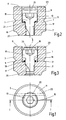
- a gas filling screw 1 is screwed as a closure element in a connection piece 3, on the gas side of a hydraulic accumulator not shown as filling connection for filling with a working gas, such as nitrogen gas, or as Test connection is provided. It is understood that the invention can equally be provided as a safety device for closure elements of another type.
- Fig. 1 to 3 show a first embodiment in which the connecting piece 3 has a generally circular cylindrical shape, wherein, concentric to the longitudinal axis 5, in which the gas side of the hydraulic accumulator, not shown end region, a threaded bore 7 is formed. On the other, outer end closes to the threaded hole 7 opposite to this extended inner hollow cylinder 9, which is also concentric to the axis 5 and at the outer end 11 of the connecting piece 3 is open. Within the hollow cylinder 9, the head 13 of the screw 1 is received. With the help of an in-head 13 hexagon socket 15, the screw 1 is screwed with its shaft 17 with the threaded hole 7, so that the screw 1 normally in Fig.
- the sealing arrangement consists of an outer soft iron ring 21 and an elastomeric ring 19 surrounding the shaft 17 of the screw 1.
- Fig. 3 shows that when unscrewing the screw 1, the shaft 17 of the screw 1 has moved in the threaded bore 7 to the outside, the distance of the displacement by the system at the as blocking element Serving cylinder block 25 in an in Fig. 3 limit position shown is limited.
- the lifting of the bottom of the head 13 of the screw 1 from the sealing element 19 leads to the release of a flow path, wherein the passage size determined by the extent of migration of the shaft 17 in the threaded hole 7.
- Cylinderkerb Due to the arrangement of acting as a blocking element Cylinderkerb turns 25 while the screw 1 is protected against ejection from the connecting piece 3, because by limiting the path length when unscrewing at least partially threaded access of the shaft 17 in the threaded hole 7 remains.
- the blocking element is formed in this embodiment by a snap ring 35 which is secured in an annular groove 37 which, as before the transverse bore 23, is arranged in the vicinity of the outer end 11 of the connecting piece 13.
- the annular groove 37 is incorporated in the inner wall of the hollow cylinder 9. Since the breaking of the snap ring 35 after the tightening of the screw 1 is carried out quickly and easily, this embodiment is characterized by a special ease of installation, the additional advantage of low production costs is given because snap rings of desired dimensions as common commercial goods are available inexpensively.
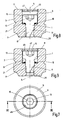
- Fig. 7 to 9 shown third embodiment which differs from the example described above only insofar when instead of an annular groove 37 with a circular groove cross-section now a corresponding annular groove 47 is provided, which has a rectangular groove cross-section and is provided for receiving a spring-locking ring 45. Since the other construction and operation is consistent with the other embodiments, a more detailed description is unnecessary. As already indicated, even with such a spring-locking ring 45 both a special ease of installation given and the advantage of low production costs, since such circlips 45 are also available inexpensively available as a commodity.
- the longitudinal narrow notch which is denoted by 20 in the preceding examples, is made longer and in FIGS. 11 and 12 denoted by 40.
- the length of the notch 40 is selected so that in the in Fig. 12 shown, open state of the screw, the notch 40 extends beyond the end 42 of the threads of the threaded hole 7 out so far that in the open state, the permeability is improved, so a lighter gas passage is enabled.
- an additional securing means is provided in this embodiment for the end position limiting when loosening the screw 1.
- a blocking element is also present here, which is formed by a snap ring 55 seated in an annular groove 37.
- a torque limiting device which limits the transferable to the screw plug 1 when releasing torque exists.
- FIGS. 11 and 12 show, for this purpose, the head 13 of the screw 1 is screwed in the hexagon socket 15 surrounding end portion, so that a side wall the hexagon socket 15 forming, relatively thin-walled sleeve 59 is formed.
- the wall thickness of the sleeve 59 is chosen so that when loosening the screw 1, when this in the in Fig.
- the sleeve 59 is sheared off, if an attempt is made to screw by increasing the torque even further screw out the screw 1. A further torque transmission is no longer possible after elimination of the hexagon socket 15 defining wall parts. Accordingly, since the maximum supporting force to be applied by the blocking element is limited, a short snap ring 55 can be used as the blocking element, in which the ring ends form a relatively large gap 46, see Fig. 10 , Such a snap ring 55 can be installed very quickly and easily.
Abstract
Description
Die Erfindung betrifft eine Sicherheitseinrichtung mit Behälter zum Einschließen von Druckmedien, insbesondere in Form hydropneumatischer Einrichtungen wie Hydrospeicher, wobei an einem Füll- oder Prüfanschluss als Verschlußeinrichtung eine Verschraubung mit einer am Anschluss in Gewindeeingriff befindlichen Verschlußschraube vorhanden ist, die beim Festziehen der Verschraubung den Anschluss sperrt und beim Lösen einen Strömungsweg durch den Anschluss freigibt.The invention relates to a safety device with container for enclosing pressure media, in particular in the form of hydropneumatic devices such as hydraulic accumulator, wherein at a filling or test port closure device as a screw with a threaded connection located on the threaded connector screw is present, which locks the connection when tightening the screw and releasing a flow path through the port upon release.
Bei hydropneumatischen Einrichtungen, wie Membranspeicher oder Kolbenspeicher, ist es Stand der Technik, Füllvorgänge oder Prüfvorgänge, bei denen eine Überwachung des Gasfülldruckes vorgenommen wird, in der Weise durchzuführen, dass am betreffenden Füll- oder Prüfanschluss eine Verschlußschraube, die im festgezogenen Zustand den Anschluss gasdicht sperrt, so weit gelöst wird, dass ein Strömungsweg mit einer für den Fülloder Prüfvorgang ausreichenden Durchlassgröße zustande kommt. Die Durchführung derartiger Vorgänge gestaltet sich verhältnismäßig problemlos, wenn vor dem Lösen der Verschlußschraube eine Füll- und Prüfeinrichtung am Behälteranschluss angebracht wird. Wird ohne Benutzung einer solchen am Anschluss fest angebrachten Einrichtung gearbeitet; dann besteht ein nicht unbeträchtliches Gefahrenpotential, falls unsachgemäß, d. h. nicht vorschriftsmäßig, gearbeitet wird. Vorschriftsgemäß ist hierbei so vorzugehen, dass die Verschlußschraube, beispielsweise mittels eines manuell betätigten Inbusschlüssels, lediglich um einen geringen Betrag, etwa in der Größenordnung einer halben Umdrehung, gelöst wird. Wird diese Vorschrift nicht eingehalten und die Schraube nicht nur gelöst, sondern zu weit heraus gedreht, besteht die Gefahr, dass die Verschlußschraube durch noch nicht abgebauten Gasdruck heraus und, falls am Anschluss keine Füllund Prüfeinrichtung angebracht ist, vom Behälter weg geschleudert wird, was die Umgebung gefährdet und eine entsprechende Unfallgefahr für das Personal darstellt. Diese Gefahr besteht vor allem dann, wenn anstelle eines manuellen Drehwerkzeuges ein angetriebenes Werkzeug, beispielsweise ein Akku-Bohrschrauber verwendet wird.In hydropneumatic devices, such as diaphragm accumulator or piston accumulator, it is state of the art, filling operations or test procedures, in which a monitoring of the gas filling pressure is carried out in such a way that at the relevant filling or test port a screw plug, the gastight in the tightened state the connection locks, is released so far that a flow path with a sufficient for the Fülloder test process orifice size is achieved. The implementation of such operations designed relatively easily if a filling and testing device is attached to the container port before loosening the screw plug. Is worked without using such a permanently attached to the connection device; then there is a not inconsiderable danger potential if improperly, ie not in accordance with regulations, is being worked on. In accordance with the regulations, this procedure is such that the closure screw, for example by means of a manual actuated Allen key, only by a small amount, about the order of half a revolution, is solved. If this requirement is not met and the screw not only loosened, but turned out too far, there is a risk that the screw plug is thrown out of the container by gas pressure not yet released and, if there is no filling and testing device on the connection, which causes the Environment endangered and represents a corresponding accident risk for the staff. This danger exists especially if, instead of a manual turning tool, a driven tool, for example a cordless drill, is used.
Durch die
Ausgehend von diesem Stand der Technik liegt der Erfindung die Aufgabe zugrunde, eine Sicherheitseinrichtung mit Behälter zu schaffen, die gegenüber den bekannten Lösungen eine erhöhte Sicherheit gewährleistet, insbesondere bei den eingangs erwähnten Tätigkeiten eine Gefährdung der Umwelt verhindert.Based on this prior art, the present invention seeks to provide a safety device with container, which ensures increased safety over the known solutions, especially in the activities mentioned above, a threat to the environment.
Erfindungsgemäß ist diese Aufgabe durch eine Sicherheitseinrichtung gelöst, die die Merkmale des Patentanspruches 1 in seiner Gesamtheit aufweist.According to the invention this object is achieved by a safety device having the features of
Danach besteht eine wesentliche Besonderheit der Erfindung darin, dass der Anschlußstutzen einen dem Behälterinnenraum benachbarten Abschnitt mit der Gewindebohrung für den Schaft der Verschlußschraube und einen sich anschließenden Abschnitt in Form eines Hohlzylinders für die Aufnahme des Kopfes der Verschlußschraube aufweist und dass das Blockierelement am Hohlzylinder so verankert ist, dass es ins Innere des Hohlzylinders ragende Anschlagflächen bildet, die durch Anlaufen des Kopfes der Verschlußschraube deren Bewegung aus der Verschlußstellung begrenzen. Hierdurch ist die Gefahr eines Herausschleuderns der Schraube mit Sicherheit aufgeschlossen.Thereafter, a significant feature of the invention is that the connecting piece has a portion adjacent to the container interior with the threaded bore for the shaft of the screw plug and a subsequent section in the form of a hollow cylinder for receiving the head of the screw plug and that the blocking element anchored to the hollow cylinder so is that it forms into the interior of the hollow cylinder projecting abutment surfaces, which limit their movement from the closed position by starting the head of the screw plug. As a result, the risk of ejection of the screw is unlocked with certainty.
Wenn hierbei am Boden des Hohlzylinders am Öffnungsrand der Gewindebohrung eine Dichtungsanordnung vorgesehen ist, an der bei der Verschlußstellung die Unterseite des Kopfes der Verschlußschraube abdichtend anliegt, kann die Wegstrecke der Bewegung der Verschlußschraube vorzugsweise auf eine Endlage begrenzt sein, bei der zwischen Dichtungsanordnung und Kopf der Verschlußschraube ein derartiger Abstand gegeben ist, dass der Strömungsweg für einen Mediendurchtritt gebildet ist.If in this case at the bottom of the hollow cylinder at the opening edge of the threaded bore a seal arrangement is provided on the abutting at the closed position, the underside of the head of the screw plug, the distance of movement of the screw plug may preferably be limited to an end position in which between seal assembly and head of Placement screw is given such a distance that the flow path is formed for a media passage.
Durch den verbleibenden Gewindeeingriff der Verschlußschraube besteht auch die vorteilhafte Möglichkeit, für das Blockierelement eine einfache und montagefreundliche Bauweise vorzusehen, weil die Sicherheitswirkung bereits mit verhältnismäßig geringen, vom Blockierelement auf die Schraube ausgeübten Sperrkräften gegeben ist.By the remaining threaded engagement of the screw plug is also the advantageous possibility for the blocking element a simple and to provide easy to install, because the safety effect is already given with relatively small, exerted by the blocking element on the screw locking forces.
Da, wie bereits erwähnt, die Wegbegrenzung der Verschlußschraube bereits erfolgt, bevor diese den Eingriff der Verschraubung verlassen hat, kann für das Blockierelement eine einfache Bauweise vorgesehen sein. So kann das Blockierelement beispielsweise durch einen Zylinderkerbstift gebildet sein, der im äußeren Randbereich des Hohlzylinders in dessen Wandung in einer Bohrung sitzt, die quer zur Zylinderachse verläuft. Bei einer alternativen Lösung, die sich durch eine besondere Montagefreundlichkeit auszeichnet, ist das Blockierelement durch einen Sprengring oder einen federnden Sicherungsring gebildet, der in einer im äußeren Randbereich in der Innenwand des Hohlzylinders gebildeten Ringnut sitzt.Since, as already mentioned, the travel limit of the screw plug already takes place before it has left the engagement of the screw connection, a simple construction can be provided for the blocking element. Thus, the blocking element may for example be formed by a Zylinderkerbstift in the outer edge region of the hollow cylinder in the wall in sits a bore which is transverse to the cylinder axis. In an alternative solution, which is characterized by a special ease of installation, the blocking element is formed by a snap ring or a resilient retaining ring which sits in a formed in the outer edge region in the inner wall of the hollow cylinder annular groove.
Bei besonders vorteilhaften Ausführungsbeispielen kann zusätzlich zu dem Blockierelement als weiteres Mittel zur Begrenzung der Wegstrecke der Bewegung der Verschlußschraube eine Einrichtung vorhanden sein, die das auf die Verschlußschraube beim Lösen übertragbare Drehmoment begrenzt. Durch die Begrenzung des beim Herausdrehen der Schraube aufbringbaren Drehmomentes sind an die Strukturfestigkeit des Blockierelementes nur besonders geringe Anforderungen zu stellen, so dass beispielsweise kurze Sprengringe, die besonders montagefreundliche sind, als Blockierelement Anwendung finden können.In particularly advantageous embodiments, in addition to the blocking element as a further means for limiting the distance of movement of the screw plug, a device may be present which limits the transferable to the screw plug during release torque. Due to the limitation of the torque which can be applied when unscrewing the screw, the structural strength of the blocking element requires only particularly low requirements, so that, for example, short snap rings, which are particularly easy to assemble, can be used as a blocking element.
Bei einer Verschlußschraube mit einem mit Innensechskant versehenen Kopf kann die das Drehmoment begrenzende Einrichtung so ausgebildet sein, dass der Kopf zur Bildung einer den Innensechskant umgebenden Hülse in seinem Endabschnitt einen verringerten Außendurchmesser aufweist und dass die Wandstärke der Hülse derart gewählt ist, dass diese beim Überschreiten eines bestimmten, an der Wand des Innensechskant wirkenden Drehmomentes abschert. Nach Abscheren der die Wand des Innensechskant bildenden Hülse läßt sich mittels eines betreffenden Drehwerkzeuges kein weiteres Drehmoment auf den Schraubenkopf übertragen.In a cap screw with a hexagon head, the torque limiting device may be formed such that the head has a reduced outer diameter in its end portion to form a hex socket surrounding the hexagon socket, and the wall thickness of the sleeve is selected to exceed this a certain, acting on the wall of the hexagon socket torque shears off. After shearing the sleeve forming the wall of the hexagon socket no further torque can be transmitted to the screw head by means of a respective turning tool.
Nachstehend ist die Erfindung anhand von in der Zeichnung dargestellten Ausführungsbeispielen im Einzelnen erläutert. Es zeigen:
-
Fig. 1 eine Draufsicht eines Anschlußstutzens am Gas- Füllanschluß eines nicht gezeigten Hydrospeichers, versehen mit einem Ausführungsbeispiel der erfindungsgemäßen Sicherheitseinrichtung; -
Fig. 2 einen Längsschnitt des Anschlußstutzens vonFig. 1 , entsprechend der Schnittlinie I-I vonFig. 1 ; -
Fig. 3 einen derFig. 2 entsprechenden Längsschnitt, der den Betriebszustand bei wirksam gewordener Sicherheitseinrichtung zeigt; -
Fig. 4 eine derFig. 1 entsprechende Draufsicht, jedoch versehen mit einem zweiten Ausführungsbeispiel der Sicherheitseinrichtung; -
Fig. 5 und 6 Längsschnitte entsprechend der Schnittlinie IV-IV vonFig. 4 , wobeiFig. 6 wiederum des Betriebszustand bei wirksam gewordener Sicherheitseinrichtung zeigt; -
Fig. 7 eine denFig. 1 und4 entsprechende Draufsicht, jedoch versehen mit einem dritten Ausführungsbeispiel der Sicherheitseinrichtung; -
Fig. 8 und 9 Längsschnitte entsprechend der Schnittlinie VII-VII vonFig. 7 , wobei inFig. 9 wiederum der Betriebszustand bei wirksam gewordener Sicherheitseinrichtung gezeigt ist; -
Fig. 10 eine denFig. 1 ,4 und7 entsprechende Draufsicht eines vierten Ausführungsbeispieles und -
Fig. 11 und 12 Längsschnitte entsprechend der Schnittlinie X-X vonFig. 10 , wobei inFig. 12 wiederum der Zustand der gelösten Verschraubung gezeigt ist.
-
Fig. 1 a plan view of a connection piece at the gas filling connection of a hydraulic accumulator, not shown, provided with an embodiment of the safety device according to the invention; -
Fig. 2 a longitudinal section of the connecting piece ofFig. 1 , according to the section line II ofFig. 1 ; -
Fig. 3 one of theFig. 2 corresponding longitudinal section showing the operating state when activated safety device; -
Fig. 4 one of theFig. 1 corresponding plan view, however, provided with a second embodiment of the safety device; -
FIGS. 5 and 6 Longitudinal sections corresponding to the section line IV-IV ofFig. 4 , in whichFig. 6 again shows the operating state when the safety device has become active; -
Fig. 7 a theFig. 1 and4 corresponding plan view, however, provided with a third embodiment of the safety device; -
8 and 9 Longitudinal sections corresponding to the section line VII-VII ofFig. 7 , where inFig. 9 again the operating state is shown when the safety device has become active; -
Fig. 10 a theFig. 1 .4 and7 corresponding plan view of a fourth embodiment and -
FIGS. 11 and 12 Longitudinal sections corresponding to the section line XX ofFig. 10 , where inFig. 12 Again, the state of the dissolved screw is shown.
Die Erfindung ist nachstehend unter Bezugnahme auf die Zeichnung anhand von Ausführungsbeispielen beschrieben, bei denen eine Gasfüllschraube 1 als Verschlußelement in einem Anschlußstutzen 3 verschraubt ist, der an der Gasseite eines nicht gezeigten Hydrospeichers als Füllanschluß für die Befüllung mit einem Arbeitsgas, wie Stickstoffgas, oder als Prüfanschluss vorgesehen ist. Es versteht sich, dass die Erfindung gleichermaßen als Sicherheitseinrichtung für Verschlußelemente anderer Art vorgesehen sein kann.The invention is described below with reference to the drawing with reference to embodiments in which a
In der Nähe des äußeren Endes 11 des Anschlußstutzens 3 ist die Wand des Hohlzylinders 9 von einer zur Achse 5 senkrechten Querbohrung 23 durchzogen, die den Sitz für einen Zylinderkerbstift 25 bildet, der in einem Montagevorgang eingesetzt wird, nachdem die Schraube 1 eingeschraubt und in ihrer Verschlußstellung festgezogen ist, wie dies in
Entsprechendes gilt auch für das in
Das in den
Zum anderen ist bei diesem Ausführungsbeispiel für die Endlagenbegrenzung beim Lösen der Schraube 1 ein zusätzliches Sicherungsmittel vorgesehen. Wie bei den zuvor beschriebenen Beispielen ist auch hier ein Blokkierelement vorhanden, das durch einen in einer Ringnut 37 sitzenden Sprengring 55 gebildet ist. Zusätzlich hierzu ist eine Drehmoment-Begrenzungseinrichtung, die das auf die Verschlußschraube 1 beim Lösen übertragbare Drehmoment begrenzt, vorhanden. Wie
Claims (7)
- A safety device with a container for holding pressure media, in particular in the form of hydropneumatic devices such as hydraulic accumulators, on a filling or checking port the closure device being a screw connection with a closure screw (1) which is in threaded engagement on the port (3) and which, when the screw connection is tightened, blocks the port (3), and when loosened, clears a flow path through the port (3), a means (25, 35, 45, 55, 59) being provided which, when the screw connection is loosened, limits the motion of the closure screw (1) to a path in which the threaded engagement is maintained, the closure screw (1) being screwed to a port (3) of the container, and a blocking element (25, 35, 45, 55) anchored in the port (3) being provided as a means which limits the free path of the closure screw (1) which moves relative to the threaded hole (7) in the port (3), characterised in that the port has a section adjacent to the container interior with the threaded hole (7) for the shaft (17) of the closure screw (1) and an adjoining section in the form of a hollow cylinder (9) for holding the head (13) of the closure screw (1), and that the blocking element (25, 35, 45, 55) is anchored on the hollow cylinder (9) such that it forms stop surfaces which project into the interior of the hollow cylinder (9) and which limit the movement of the closure screw (1) out of the closure position by coming into direct contact with the head (13) of the screw.
- The safety device according to Claim 1, characterised in that on the bottom of the hollow cylinder (9) on the opening edge of the threaded hole (7) there is a sealing arrangement (19, 21) which in the closed position is adjoined by the bottom of the head (13) of the closure screw (1) to form a seal, and that the path of motion of the closure screw (1) is limited to an end position in which between the sealing arrangement (19, 21) and the head (13) of the closure screw there is a distance such that the flow path for passage of the medium is formed.
- The safety device according to Claim 1 or 2, characterised in that the blocking element is formed by a cylindrical grooved pin (25) which in the outer edge region of the hollow cylinder (9) in its wall sits in a hole (23) which runs transversely to the axis (5) of the cylinder.
- The safety device according to any of Claims 1 to 3, characterised in that the blocking element is formed by a snap ring (35, 55) or an elastic locking ring (45) which sits in an annular groove (37 and 47) formed in the outer edge region in the inside wall of the hollow cylinder (9).
- The safety device according to any of Claims 1 to 4, characterised in that in addition to the blocking element (25, 35, 45, 55) as another means for limiting the path of motion of the closure screw (1) there is a device (59) which limits the torque which can be transmitted to the closure screw (1) as it is being unscrewed.
- The safety device according to Claim 5, characterised in that the closure screw (1) has a head (13) with a hexagon socket (15), that the head (13) has a reduced outside diameter in its end section (61) for forming a sleeve (59) which surrounds the hexagon socket (15) and that the wall thickness of the sleeve (59) is chosen such that it shears off when a certain torque acting on the wall of the hexagon socket (15) is exceeded.
- The safety device according to any of Claims 1 to 6, characterised in that the closure screw (1) is a gas filling screw which sits in a port (3) which is located as a filling port on the gas side of a hydraulic accumulator.
Applications Claiming Priority (2)
| Application Number | Priority Date | Filing Date | Title |
|---|---|---|---|
| DE200710032207 DE102007032207A1 (en) | 2007-07-11 | 2007-07-11 | Safety device for media enclosing containers |
| PCT/EP2008/003729 WO2009006961A1 (en) | 2007-07-11 | 2008-05-09 | Safety device for pressure-medium-containing tanks |
Publications (3)
| Publication Number | Publication Date |
|---|---|
| EP2176554A1 EP2176554A1 (en) | 2010-04-21 |
| EP2176554B1 true EP2176554B1 (en) | 2012-08-08 |
| EP2176554B8 EP2176554B8 (en) | 2013-09-11 |
Family
ID=39687095
Family Applications (1)
| Application Number | Title | Priority Date | Filing Date |
|---|---|---|---|
| EP08749412.6A Active EP2176554B8 (en) | 2007-07-11 | 2008-05-09 | Safety device for pressure-medium-containing tanks |
Country Status (5)
| Country | Link |
|---|---|
| US (1) | US9534614B2 (en) |
| EP (1) | EP2176554B8 (en) |
| JP (1) | JP2010532846A (en) |
| DE (1) | DE102007032207A1 (en) |
| WO (1) | WO2009006961A1 (en) |
Cited By (1)
| Publication number | Priority date | Publication date | Assignee | Title |
|---|---|---|---|---|
| EP4310371A1 (en) | 2022-07-20 | 2024-01-24 | Oventrop GmbH & Co. KG | Faucet with valve element |
Families Citing this family (8)
| Publication number | Priority date | Publication date | Assignee | Title |
|---|---|---|---|---|
| EP2626571B1 (en) * | 2012-02-08 | 2019-10-23 | Grundfos Holding A/S | Circlip with force limitation |
| WO2020026074A1 (en) | 2018-08-01 | 2020-02-06 | Fastest, Inc. | Service connection valve assembly |
| CN110397736B (en) * | 2018-10-15 | 2024-03-22 | 沈阳工业大学 | Bidirectional air inlet and outlet valve capable of guaranteeing flatness of outer wall and locking structure thereof |
| AT17069U1 (en) * | 2019-08-28 | 2021-04-15 | Andreas Zieger Dipl Ing | MANUALLY OPERATED VALVE |
| AT17019U1 (en) * | 2019-08-28 | 2021-02-15 | Zieger Dipl Ing Andreas | |
| IT201900019082A1 (en) * | 2019-10-16 | 2021-04-16 | Tapel Di Mastromatteo Ciro & C S A S | SELF-CLEANING OUTDOOR OR BUILT-IN TAP |
| FR3109977A1 (en) * | 2020-05-08 | 2021-11-12 | Cryl | Safety decompression equipment for hydraulic circuit |
| KR102566784B1 (en) * | 2021-04-29 | 2023-08-16 | (주)모토닉 | Safety valve apparatus for hydrogen high pressure regulator |
Family Cites Families (13)
| Publication number | Priority date | Publication date | Assignee | Title |
|---|---|---|---|---|
| DE68519C (en) | E. TH. FOERSTER in Berlin, Alte Jakobstr. 5 | Closures on containers for high pressure gases | ||
| US1733309A (en) * | 1928-06-05 | 1929-10-29 | Leonard Charles Warren | Valve mechanism |
| US2827913A (en) * | 1955-07-28 | 1958-03-25 | Wagner William | Self-tapping valve for tubes, pipes, tanks and other conduits and containers |
| US3323546A (en) * | 1964-07-01 | 1967-06-06 | United Aircraft Prod | Hydraulic bleed valve |
| US3472427A (en) * | 1967-04-20 | 1969-10-14 | Pennsalt Chemicals Corp | Destructible valve |
| DE2000355A1 (en) * | 1970-01-07 | 1971-07-15 | Langen & Co | Hydraulic accumulator |
| DE2238356A1 (en) * | 1972-08-04 | 1974-02-14 | Fichtel & Sachs Ag | FILLING VALVE WITH SLIDING VALVE BODY FOR HYDROPNEUMATIC SUSPENSIONS OF MOTOR VEHICLES |
| US3865344A (en) * | 1972-10-25 | 1975-02-11 | Carrier Corp | Retaining ring |
| DE2551124A1 (en) * | 1975-11-14 | 1977-05-26 | Bosch Gmbh Robert | FILLING DEVICE FOR THE GAS COMPARTMENT OF A PRESSURE VESSEL |
| EP0047107B1 (en) * | 1980-08-29 | 1984-07-11 | Brd Company Limited | Splined joints |
| US4601305A (en) * | 1984-11-29 | 1986-07-22 | Nordskog Robert A | Compact gas compressor check valve |
| DE19511525C2 (en) * | 1995-03-29 | 1999-11-04 | Mannesmann Rexroth Ag | Hydraulic cylinder with a function screw and a fuse for it |
| US5713705A (en) * | 1996-03-01 | 1998-02-03 | Gruenbichler; Carl | Fastener bolt with limited torque head |
-
2007
- 2007-07-11 DE DE200710032207 patent/DE102007032207A1/en not_active Withdrawn
-
2008
- 2008-05-09 JP JP2010515356A patent/JP2010532846A/en active Pending
- 2008-05-09 US US12/451,475 patent/US9534614B2/en active Active
- 2008-05-09 EP EP08749412.6A patent/EP2176554B8/en active Active
- 2008-05-09 WO PCT/EP2008/003729 patent/WO2009006961A1/en active Application Filing
Cited By (2)
| Publication number | Priority date | Publication date | Assignee | Title |
|---|---|---|---|---|
| EP4310371A1 (en) | 2022-07-20 | 2024-01-24 | Oventrop GmbH & Co. KG | Faucet with valve element |
| DE102022118129A1 (en) | 2022-07-20 | 2024-01-25 | Oventrop Gmbh & Co. Kg | Fitting with valve element |
Also Published As
| Publication number | Publication date |
|---|---|
| JP2010532846A (en) | 2010-10-14 |
| DE102007032207A1 (en) | 2009-01-15 |
| EP2176554A1 (en) | 2010-04-21 |
| WO2009006961A1 (en) | 2009-01-15 |
| EP2176554B8 (en) | 2013-09-11 |
| US20100126597A1 (en) | 2010-05-27 |
| US9534614B2 (en) | 2017-01-03 |
Similar Documents
| Publication | Publication Date | Title |
|---|---|---|
| EP2176554B1 (en) | Safety device for pressure-medium-containing tanks | |
| EP0608491B1 (en) | Pressure relief valve for large rate of flow | |
| EP1934404B1 (en) | Friction bolt and expansion adaptor for said anchor | |
| EP3004702B1 (en) | Combination of a housing and a valve | |
| EP3479008A1 (en) | Tank valve | |
| DE2756084B2 (en) | Screw lock | |
| DE102014010570B4 (en) | Coupling part for a coupling for pressure fluid lines | |
| DE102015222640B4 (en) | Coupling element and valve tappet for a coupling for connecting pressure medium lines | |
| DE102015116301A1 (en) | "Screw" | |
| DE102014100758B4 (en) | Play-free plug connection for pipe and hose lines | |
| DE102015109278A1 (en) | Connection system, clamping screw, method for connecting two components and tool for the production of the connection system | |
| EP2529137B1 (en) | Pressure relief valve | |
| EP1502022B1 (en) | Fuel distribution pipe for motor vehicle injection devices, in particular for common rail systems | |
| EP1114252A1 (en) | Connection and housing for a fuel injection system with a high-pressure fuel accumulator | |
| DE2418598A1 (en) | Blind bore anchor bolt - has at least one tapered expansion part forced outwardly by draw bolt | |
| DE3239930A1 (en) | Hydraulically controllable shut-off valve, especially for securing a pipe fracture | |
| WO2011020696A2 (en) | Coupling for connecting anchor rods | |
| DE60208713T2 (en) | COUPLING DEVICE FOR PRESSURE FLUID PIPES AND METHOD FOR PRODUCING SUCH A COUPLING WITH A LEAKNUT FOR INDICATING A LEAKAGE | |
| EP3514418B1 (en) | Cartridge valve for a valve manifold | |
| DE102018122701A1 (en) | Holder system for attaching a container to a vehicle | |
| DE112014000059T5 (en) | Configuration for closing an oil pressure circuit opening | |
| DE10356597B3 (en) | Locking cylinder unit for hydraulically actuated component has several locking bodies in form of separately movable locking bolts | |
| DE102006042096B4 (en) | Arrangement for closing a high-pressure bore | |
| WO2008043773A1 (en) | Unscrewing safeguard arrangement for a screw-in element | |
| EP4310371A1 (en) | Faucet with valve element |
Legal Events
| Date | Code | Title | Description |
|---|---|---|---|
| PUAI | Public reference made under article 153(3) epc to a published international application that has entered the european phase |
Free format text: ORIGINAL CODE: 0009012 |
|
| 17P | Request for examination filed |
Effective date: 20090926 |
|
| AK | Designated contracting states |
Kind code of ref document: A1 Designated state(s): AT BE BG CH CY CZ DE DK EE ES FI FR GB GR HR HU IE IS IT LI LT LU LV MC MT NL NO PL PT RO SE SI SK TR |
|
| AX | Request for extension of the european patent |
Extension state: AL BA MK RS |
|
| 17Q | First examination report despatched |
Effective date: 20100716 |
|
| DAX | Request for extension of the european patent (deleted) | ||
| GRAP | Despatch of communication of intention to grant a patent |
Free format text: ORIGINAL CODE: EPIDOSNIGR1 |
|
| GRAS | Grant fee paid |
Free format text: ORIGINAL CODE: EPIDOSNIGR3 |
|
| GRAA | (expected) grant |
Free format text: ORIGINAL CODE: 0009210 |
|
| AK | Designated contracting states |
Kind code of ref document: B1 Designated state(s): AT BE BG CH CY CZ DE DK EE ES FI FR GB GR HR HU IE IS IT LI LT LU LV MC MT NL NO PL PT RO SE SI SK TR |
|
| REG | Reference to a national code |
Ref country code: GB Ref legal event code: FG4D Free format text: NOT ENGLISH |
|
| REG | Reference to a national code |
Ref country code: CH Ref legal event code: EP Ref country code: AT Ref legal event code: REF Ref document number: 569928 Country of ref document: AT Kind code of ref document: T Effective date: 20120815 |
|
| REG | Reference to a national code |
Ref country code: IE Ref legal event code: FG4D Free format text: LANGUAGE OF EP DOCUMENT: GERMAN |
|
| REG | Reference to a national code |
Ref country code: DE Ref legal event code: R096 Ref document number: 502008007894 Country of ref document: DE Effective date: 20121004 |
|
| REG | Reference to a national code |
Ref country code: SE Ref legal event code: TRGR |
|
| REG | Reference to a national code |
Ref country code: NL Ref legal event code: VDEP Effective date: 20120808 |
|
| REG | Reference to a national code |
Ref country code: LT Ref legal event code: MG4D Effective date: 20120808 |
|
| PG25 | Lapsed in a contracting state [announced via postgrant information from national office to epo] |
Ref country code: CY Free format text: LAPSE BECAUSE OF FAILURE TO SUBMIT A TRANSLATION OF THE DESCRIPTION OR TO PAY THE FEE WITHIN THE PRESCRIBED TIME-LIMIT Effective date: 20120808 Ref country code: HR Free format text: LAPSE BECAUSE OF FAILURE TO SUBMIT A TRANSLATION OF THE DESCRIPTION OR TO PAY THE FEE WITHIN THE PRESCRIBED TIME-LIMIT Effective date: 20120808 Ref country code: NO Free format text: LAPSE BECAUSE OF FAILURE TO SUBMIT A TRANSLATION OF THE DESCRIPTION OR TO PAY THE FEE WITHIN THE PRESCRIBED TIME-LIMIT Effective date: 20121108 Ref country code: LT Free format text: LAPSE BECAUSE OF FAILURE TO SUBMIT A TRANSLATION OF THE DESCRIPTION OR TO PAY THE FEE WITHIN THE PRESCRIBED TIME-LIMIT Effective date: 20120808 Ref country code: IS Free format text: LAPSE BECAUSE OF FAILURE TO SUBMIT A TRANSLATION OF THE DESCRIPTION OR TO PAY THE FEE WITHIN THE PRESCRIBED TIME-LIMIT Effective date: 20121208 |
|
| PG25 | Lapsed in a contracting state [announced via postgrant information from national office to epo] |
Ref country code: PL Free format text: LAPSE BECAUSE OF FAILURE TO SUBMIT A TRANSLATION OF THE DESCRIPTION OR TO PAY THE FEE WITHIN THE PRESCRIBED TIME-LIMIT Effective date: 20120808 Ref country code: SI Free format text: LAPSE BECAUSE OF FAILURE TO SUBMIT A TRANSLATION OF THE DESCRIPTION OR TO PAY THE FEE WITHIN THE PRESCRIBED TIME-LIMIT Effective date: 20120808 Ref country code: PT Free format text: LAPSE BECAUSE OF FAILURE TO SUBMIT A TRANSLATION OF THE DESCRIPTION OR TO PAY THE FEE WITHIN THE PRESCRIBED TIME-LIMIT Effective date: 20121210 Ref country code: LV Free format text: LAPSE BECAUSE OF FAILURE TO SUBMIT A TRANSLATION OF THE DESCRIPTION OR TO PAY THE FEE WITHIN THE PRESCRIBED TIME-LIMIT Effective date: 20120808 Ref country code: GR Free format text: LAPSE BECAUSE OF FAILURE TO SUBMIT A TRANSLATION OF THE DESCRIPTION OR TO PAY THE FEE WITHIN THE PRESCRIBED TIME-LIMIT Effective date: 20121109 |
|
| PG25 | Lapsed in a contracting state [announced via postgrant information from national office to epo] |
Ref country code: NL Free format text: LAPSE BECAUSE OF FAILURE TO SUBMIT A TRANSLATION OF THE DESCRIPTION OR TO PAY THE FEE WITHIN THE PRESCRIBED TIME-LIMIT Effective date: 20120808 |
|
| PG25 | Lapsed in a contracting state [announced via postgrant information from national office to epo] |
Ref country code: CZ Free format text: LAPSE BECAUSE OF FAILURE TO SUBMIT A TRANSLATION OF THE DESCRIPTION OR TO PAY THE FEE WITHIN THE PRESCRIBED TIME-LIMIT Effective date: 20120808 Ref country code: RO Free format text: LAPSE BECAUSE OF FAILURE TO SUBMIT A TRANSLATION OF THE DESCRIPTION OR TO PAY THE FEE WITHIN THE PRESCRIBED TIME-LIMIT Effective date: 20120808 Ref country code: DK Free format text: LAPSE BECAUSE OF FAILURE TO SUBMIT A TRANSLATION OF THE DESCRIPTION OR TO PAY THE FEE WITHIN THE PRESCRIBED TIME-LIMIT Effective date: 20120808 Ref country code: EE Free format text: LAPSE BECAUSE OF FAILURE TO SUBMIT A TRANSLATION OF THE DESCRIPTION OR TO PAY THE FEE WITHIN THE PRESCRIBED TIME-LIMIT Effective date: 20120808 Ref country code: ES Free format text: LAPSE BECAUSE OF FAILURE TO SUBMIT A TRANSLATION OF THE DESCRIPTION OR TO PAY THE FEE WITHIN THE PRESCRIBED TIME-LIMIT Effective date: 20121119 |
|
| PG25 | Lapsed in a contracting state [announced via postgrant information from national office to epo] |
Ref country code: SK Free format text: LAPSE BECAUSE OF FAILURE TO SUBMIT A TRANSLATION OF THE DESCRIPTION OR TO PAY THE FEE WITHIN THE PRESCRIBED TIME-LIMIT Effective date: 20120808 |
|
| PLBE | No opposition filed within time limit |
Free format text: ORIGINAL CODE: 0009261 |
|
| 26N | No opposition filed |
Effective date: 20130510 |
|
| PLAA | Information modified related to event that no opposition was filed |
Free format text: ORIGINAL CODE: 0009299DELT |
|
| PLBE | No opposition filed within time limit |
Free format text: ORIGINAL CODE: 0009261 |
|
| STAA | Information on the status of an ep patent application or granted ep patent |
Free format text: STATUS: NO OPPOSITION FILED WITHIN TIME LIMIT |
|
| PG25 | Lapsed in a contracting state [announced via postgrant information from national office to epo] |
Ref country code: BG Free format text: LAPSE BECAUSE OF FAILURE TO SUBMIT A TRANSLATION OF THE DESCRIPTION OR TO PAY THE FEE WITHIN THE PRESCRIBED TIME-LIMIT Effective date: 20121108 |
|
| R26N | No opposition filed (corrected) |
Effective date: 20130510 |
|
| RAP2 | Party data changed (patent owner data changed or rights of a patent transferred) |
Owner name: HYDAC TECHNOLOGY GMBH |
|
| REG | Reference to a national code |
Ref country code: DE Ref legal event code: R082 Ref document number: 502008007894 Country of ref document: DE Representative=s name: BARTELS UND PARTNER PATENTANWAELTE, DE Ref country code: DE Ref legal event code: R082 Ref document number: 502008007894 Country of ref document: DE Representative=s name: BARTELS & PARTNER PATENTANWAELTE, DE |
|
| REG | Reference to a national code |
Ref country code: DE Ref legal event code: R097 Ref document number: 502008007894 Country of ref document: DE Effective date: 20130510 |
|
| REG | Reference to a national code |
Ref country code: AT Ref legal event code: HC Ref document number: 569928 Country of ref document: AT Kind code of ref document: T Owner name: HYDAC TECHNOLOGY GMBH, DE Effective date: 20130917 |
|
| BERE | Be: lapsed |
Owner name: HYDAC TECHNOLOGY G.M.B.H. Effective date: 20130531 |
|
| PG25 | Lapsed in a contracting state [announced via postgrant information from national office to epo] |
Ref country code: MC Free format text: LAPSE BECAUSE OF FAILURE TO SUBMIT A TRANSLATION OF THE DESCRIPTION OR TO PAY THE FEE WITHIN THE PRESCRIBED TIME-LIMIT Effective date: 20120808 |
|
| REG | Reference to a national code |
Ref country code: CH Ref legal event code: PL |
|
| REG | Reference to a national code |
Ref country code: FR Ref legal event code: RM Effective date: 20131223 |
|
| PG25 | Lapsed in a contracting state [announced via postgrant information from national office to epo] |
Ref country code: CH Free format text: LAPSE BECAUSE OF NON-PAYMENT OF DUE FEES Effective date: 20130531 Ref country code: LI Free format text: LAPSE BECAUSE OF NON-PAYMENT OF DUE FEES Effective date: 20130531 |
|
| REG | Reference to a national code |
Ref country code: IE Ref legal event code: MM4A |
|
| PG25 | Lapsed in a contracting state [announced via postgrant information from national office to epo] |
Ref country code: BE Free format text: LAPSE BECAUSE OF NON-PAYMENT OF DUE FEES Effective date: 20130531 |
|
| PG25 | Lapsed in a contracting state [announced via postgrant information from national office to epo] |
Ref country code: IE Free format text: LAPSE BECAUSE OF NON-PAYMENT OF DUE FEES Effective date: 20130509 |
|
| PG25 | Lapsed in a contracting state [announced via postgrant information from national office to epo] |
Ref country code: MT Free format text: LAPSE BECAUSE OF FAILURE TO SUBMIT A TRANSLATION OF THE DESCRIPTION OR TO PAY THE FEE WITHIN THE PRESCRIBED TIME-LIMIT Effective date: 20120808 |
|
| PG25 | Lapsed in a contracting state [announced via postgrant information from national office to epo] |
Ref country code: TR Free format text: LAPSE BECAUSE OF FAILURE TO SUBMIT A TRANSLATION OF THE DESCRIPTION OR TO PAY THE FEE WITHIN THE PRESCRIBED TIME-LIMIT Effective date: 20120808 |
|
| PG25 | Lapsed in a contracting state [announced via postgrant information from national office to epo] |
Ref country code: LU Free format text: LAPSE BECAUSE OF NON-PAYMENT OF DUE FEES Effective date: 20130509 Ref country code: HU Free format text: LAPSE BECAUSE OF FAILURE TO SUBMIT A TRANSLATION OF THE DESCRIPTION OR TO PAY THE FEE WITHIN THE PRESCRIBED TIME-LIMIT; INVALID AB INITIO Effective date: 20080509 |
|
| REG | Reference to a national code |
Ref country code: FR Ref legal event code: PLFP Year of fee payment: 9 |
|
| PGFP | Annual fee paid to national office [announced via postgrant information from national office to epo] |
Ref country code: AT Payment date: 20160513 Year of fee payment: 9 |
|
| REG | Reference to a national code |
Ref country code: FR Ref legal event code: PLFP Year of fee payment: 10 |
|
| REG | Reference to a national code |
Ref country code: AT Ref legal event code: MM01 Ref document number: 569928 Country of ref document: AT Kind code of ref document: T Effective date: 20170509 |
|
| PG25 | Lapsed in a contracting state [announced via postgrant information from national office to epo] |
Ref country code: AT Free format text: LAPSE BECAUSE OF NON-PAYMENT OF DUE FEES Effective date: 20170509 |
|
| REG | Reference to a national code |
Ref country code: FR Ref legal event code: PLFP Year of fee payment: 11 |
|
| PGFP | Annual fee paid to national office [announced via postgrant information from national office to epo] |
Ref country code: GB Payment date: 20180320 Year of fee payment: 11 |
|
| PGFP | Annual fee paid to national office [announced via postgrant information from national office to epo] |
Ref country code: FI Payment date: 20180503 Year of fee payment: 11 |
|
| PGFP | Annual fee paid to national office [announced via postgrant information from national office to epo] |
Ref country code: IT Payment date: 20180514 Year of fee payment: 11 Ref country code: FR Payment date: 20180404 Year of fee payment: 11 |
|
| PGFP | Annual fee paid to national office [announced via postgrant information from national office to epo] |
Ref country code: SE Payment date: 20180404 Year of fee payment: 11 |
|
| GBPC | Gb: european patent ceased through non-payment of renewal fee |
Effective date: 20190509 |
|
| PG25 | Lapsed in a contracting state [announced via postgrant information from national office to epo] |
Ref country code: SE Free format text: LAPSE BECAUSE OF NON-PAYMENT OF DUE FEES Effective date: 20190510 Ref country code: FI Free format text: LAPSE BECAUSE OF NON-PAYMENT OF DUE FEES Effective date: 20190509 |
|
| PG25 | Lapsed in a contracting state [announced via postgrant information from national office to epo] |
Ref country code: GB Free format text: LAPSE BECAUSE OF NON-PAYMENT OF DUE FEES Effective date: 20190509 Ref country code: IT Free format text: LAPSE BECAUSE OF NON-PAYMENT OF DUE FEES Effective date: 20190509 |
|
| REG | Reference to a national code |
Ref country code: SE Ref legal event code: EUG |
|
| PG25 | Lapsed in a contracting state [announced via postgrant information from national office to epo] |
Ref country code: FR Free format text: LAPSE BECAUSE OF NON-PAYMENT OF DUE FEES Effective date: 20190531 |
|
| PGFP | Annual fee paid to national office [announced via postgrant information from national office to epo] |
Ref country code: DE Payment date: 20230531 Year of fee payment: 16 |