EP2176359B1 - Mehrschichtige metallische effektpigmente, verfahren zu deren herstellung und verwendung - Google Patents
Mehrschichtige metallische effektpigmente, verfahren zu deren herstellung und verwendung Download PDFInfo
- Publication number
- EP2176359B1 EP2176359B1 EP08785037A EP08785037A EP2176359B1 EP 2176359 B1 EP2176359 B1 EP 2176359B1 EP 08785037 A EP08785037 A EP 08785037A EP 08785037 A EP08785037 A EP 08785037A EP 2176359 B1 EP2176359 B1 EP 2176359B1
- Authority
- EP
- European Patent Office
- Prior art keywords
- layer
- oxygen
- metal
- layers
- pigments
- Prior art date
- Legal status (The legal status is an assumption and is not a legal conclusion. Google has not performed a legal analysis and makes no representation as to the accuracy of the status listed.)
- Not-in-force
Links
- 239000000049 pigment Substances 0.000 title claims abstract description 342
- 230000000694 effects Effects 0.000 title claims abstract description 194
- 238000000034 method Methods 0.000 title claims abstract description 97
- 230000008569 process Effects 0.000 title abstract description 44
- 238000002360 preparation method Methods 0.000 title description 10
- 229910052760 oxygen Inorganic materials 0.000 claims abstract description 242
- 239000001301 oxygen Substances 0.000 claims abstract description 234
- 229910052751 metal Inorganic materials 0.000 claims abstract description 204
- 239000002184 metal Substances 0.000 claims abstract description 204
- QVGXLLKOCUKJST-UHFFFAOYSA-N atomic oxygen Chemical compound [O] QVGXLLKOCUKJST-UHFFFAOYSA-N 0.000 claims abstract description 29
- 239000011651 chromium Substances 0.000 claims description 100
- 239000000758 substrate Substances 0.000 claims description 61
- XAGFODPZIPBFFR-UHFFFAOYSA-N aluminium Chemical compound [Al] XAGFODPZIPBFFR-UHFFFAOYSA-N 0.000 claims description 60
- 238000000576 coating method Methods 0.000 claims description 60
- 229910052782 aluminium Inorganic materials 0.000 claims description 53
- PCHJSUWPFVWCPO-UHFFFAOYSA-N gold Chemical compound [Au] PCHJSUWPFVWCPO-UHFFFAOYSA-N 0.000 claims description 49
- 238000005240 physical vapour deposition Methods 0.000 claims description 44
- 239000011248 coating agent Substances 0.000 claims description 42
- 239000000203 mixture Substances 0.000 claims description 40
- 239000010931 gold Substances 0.000 claims description 38
- 229910052737 gold Inorganic materials 0.000 claims description 38
- BQCADISMDOOEFD-UHFFFAOYSA-N Silver Chemical compound [Ag] BQCADISMDOOEFD-UHFFFAOYSA-N 0.000 claims description 35
- 150000002739 metals Chemical class 0.000 claims description 33
- 229910052709 silver Inorganic materials 0.000 claims description 30
- 239000004332 silver Substances 0.000 claims description 28
- 229910052804 chromium Inorganic materials 0.000 claims description 25
- VYZAMTAEIAYCRO-UHFFFAOYSA-N Chromium Chemical compound [Cr] VYZAMTAEIAYCRO-UHFFFAOYSA-N 0.000 claims description 24
- 239000000126 substance Substances 0.000 claims description 17
- 239000003973 paint Substances 0.000 claims description 15
- XEEYBQQBJWHFJM-UHFFFAOYSA-N Iron Chemical compound [Fe] XEEYBQQBJWHFJM-UHFFFAOYSA-N 0.000 claims description 14
- 239000010949 copper Substances 0.000 claims description 13
- 239000006185 dispersion Substances 0.000 claims description 13
- RYGMFSIKBFXOCR-UHFFFAOYSA-N Copper Chemical compound [Cu] RYGMFSIKBFXOCR-UHFFFAOYSA-N 0.000 claims description 12
- 239000000956 alloy Substances 0.000 claims description 12
- 229910045601 alloy Inorganic materials 0.000 claims description 12
- 238000007639 printing Methods 0.000 claims description 9
- 239000010936 titanium Substances 0.000 claims description 9
- PXHVJJICTQNCMI-UHFFFAOYSA-N Nickel Chemical compound [Ni] PXHVJJICTQNCMI-UHFFFAOYSA-N 0.000 claims description 8
- 229910052796 boron Inorganic materials 0.000 claims description 8
- 229910052802 copper Inorganic materials 0.000 claims description 8
- 239000000976 ink Substances 0.000 claims description 8
- 239000004033 plastic Substances 0.000 claims description 7
- 229920003023 plastic Polymers 0.000 claims description 7
- RTAQQCXQSZGOHL-UHFFFAOYSA-N Titanium Chemical compound [Ti] RTAQQCXQSZGOHL-UHFFFAOYSA-N 0.000 claims description 5
- 230000015572 biosynthetic process Effects 0.000 claims description 5
- 239000002537 cosmetic Substances 0.000 claims description 5
- 238000009472 formulation Methods 0.000 claims description 5
- 229910052742 iron Inorganic materials 0.000 claims description 5
- 239000000843 powder Substances 0.000 claims description 5
- 229910052719 titanium Inorganic materials 0.000 claims description 5
- 229910052725 zinc Inorganic materials 0.000 claims description 5
- 239000011701 zinc Substances 0.000 claims description 5
- ZOKXTWBITQBERF-UHFFFAOYSA-N Molybdenum Chemical compound [Mo] ZOKXTWBITQBERF-UHFFFAOYSA-N 0.000 claims description 4
- ATJFFYVFTNAWJD-UHFFFAOYSA-N Tin Chemical compound [Sn] ATJFFYVFTNAWJD-UHFFFAOYSA-N 0.000 claims description 4
- HCHKCACWOHOZIP-UHFFFAOYSA-N Zinc Chemical compound [Zn] HCHKCACWOHOZIP-UHFFFAOYSA-N 0.000 claims description 4
- 239000010941 cobalt Substances 0.000 claims description 4
- 229910017052 cobalt Inorganic materials 0.000 claims description 4
- GUTLYIVDDKVIGB-UHFFFAOYSA-N cobalt atom Chemical compound [Co] GUTLYIVDDKVIGB-UHFFFAOYSA-N 0.000 claims description 4
- WPBNNNQJVZRUHP-UHFFFAOYSA-L manganese(2+);methyl n-[[2-(methoxycarbonylcarbamothioylamino)phenyl]carbamothioyl]carbamate;n-[2-(sulfidocarbothioylamino)ethyl]carbamodithioate Chemical compound [Mn+2].[S-]C(=S)NCCNC([S-])=S.COC(=O)NC(=S)NC1=CC=CC=C1NC(=S)NC(=O)OC WPBNNNQJVZRUHP-UHFFFAOYSA-L 0.000 claims description 4
- 229910052750 molybdenum Inorganic materials 0.000 claims description 4
- 239000011733 molybdenum Substances 0.000 claims description 4
- 229910052759 nickel Inorganic materials 0.000 claims description 4
- 229910052718 tin Inorganic materials 0.000 claims description 4
- 239000011135 tin Substances 0.000 claims description 4
- 230000007704 transition Effects 0.000 claims description 4
- 238000000227 grinding Methods 0.000 claims description 3
- 239000002966 varnish Substances 0.000 claims description 3
- FYYHWMGAXLPEAU-UHFFFAOYSA-N Magnesium Chemical compound [Mg] FYYHWMGAXLPEAU-UHFFFAOYSA-N 0.000 claims description 2
- 229910052749 magnesium Inorganic materials 0.000 claims description 2
- 239000011777 magnesium Substances 0.000 claims description 2
- 229910052715 tantalum Inorganic materials 0.000 claims description 2
- GUVRBAGPIYLISA-UHFFFAOYSA-N tantalum atom Chemical compound [Ta] GUVRBAGPIYLISA-UHFFFAOYSA-N 0.000 claims description 2
- 239000004411 aluminium Substances 0.000 claims 4
- 238000000151 deposition Methods 0.000 claims 1
- 230000008021 deposition Effects 0.000 claims 1
- 239000010410 layer Substances 0.000 description 577
- MYMOFIZGZYHOMD-UHFFFAOYSA-N Dioxygen Chemical compound O=O MYMOFIZGZYHOMD-UHFFFAOYSA-N 0.000 description 216
- 125000004429 atom Chemical group 0.000 description 56
- 150000004706 metal oxides Chemical class 0.000 description 53
- 238000001704 evaporation Methods 0.000 description 44
- 230000008020 evaporation Effects 0.000 description 41
- 238000005259 measurement Methods 0.000 description 40
- 238000010894 electron beam technology Methods 0.000 description 26
- 239000000523 sample Substances 0.000 description 25
- XLYOFNOQVPJJNP-UHFFFAOYSA-N water Substances O XLYOFNOQVPJJNP-UHFFFAOYSA-N 0.000 description 23
- 239000002245 particle Substances 0.000 description 22
- 229910001868 water Inorganic materials 0.000 description 22
- 230000000052 comparative effect Effects 0.000 description 20
- 238000002149 energy-dispersive X-ray emission spectroscopy Methods 0.000 description 18
- 238000004544 sputter deposition Methods 0.000 description 18
- CSCPPACGZOOCGX-UHFFFAOYSA-N Acetone Chemical compound CC(C)=O CSCPPACGZOOCGX-UHFFFAOYSA-N 0.000 description 16
- 238000004519 manufacturing process Methods 0.000 description 16
- 230000003287 optical effect Effects 0.000 description 16
- 239000013078 crystal Substances 0.000 description 14
- 238000009826 distribution Methods 0.000 description 14
- 239000010453 quartz Substances 0.000 description 14
- VYPSYNLAJGMNEJ-UHFFFAOYSA-N silicon dioxide Inorganic materials O=[Si]=O VYPSYNLAJGMNEJ-UHFFFAOYSA-N 0.000 description 14
- 239000002356 single layer Substances 0.000 description 14
- 230000005284 excitation Effects 0.000 description 13
- 229910044991 metal oxide Inorganic materials 0.000 description 13
- 229910004298 SiO 2 Inorganic materials 0.000 description 12
- 238000004833 X-ray photoelectron spectroscopy Methods 0.000 description 12
- 238000004458 analytical method Methods 0.000 description 12
- 239000000463 material Substances 0.000 description 11
- 238000007740 vapor deposition Methods 0.000 description 10
- 229920002799 BoPET Polymers 0.000 description 9
- 125000004430 oxygen atom Chemical group O* 0.000 description 9
- 230000011514 reflex Effects 0.000 description 9
- 230000007797 corrosion Effects 0.000 description 8
- 238000005260 corrosion Methods 0.000 description 8
- -1 for example Substances 0.000 description 8
- 150000001875 compounds Chemical class 0.000 description 7
- 238000010438 heat treatment Methods 0.000 description 7
- 238000001883 metal evaporation Methods 0.000 description 7
- 230000035515 penetration Effects 0.000 description 7
- 238000001228 spectrum Methods 0.000 description 7
- XEKOWRVHYACXOJ-UHFFFAOYSA-N Ethyl acetate Chemical compound CCOC(C)=O XEKOWRVHYACXOJ-UHFFFAOYSA-N 0.000 description 6
- 230000005540 biological transmission Effects 0.000 description 6
- 229910001882 dioxygen Inorganic materials 0.000 description 6
- 230000003993 interaction Effects 0.000 description 6
- 229920000139 polyethylene terephthalate Polymers 0.000 description 6
- 239000005020 polyethylene terephthalate Substances 0.000 description 6
- 230000008901 benefit Effects 0.000 description 5
- 239000011230 binding agent Substances 0.000 description 5
- 230000007423 decrease Effects 0.000 description 5
- 239000011521 glass Substances 0.000 description 5
- 239000004922 lacquer Substances 0.000 description 5
- 239000002904 solvent Substances 0.000 description 5
- 239000000725 suspension Substances 0.000 description 5
- 239000000919 ceramic Substances 0.000 description 4
- 230000008859 change Effects 0.000 description 4
- 230000001186 cumulative effect Effects 0.000 description 4
- 238000005566 electron beam evaporation Methods 0.000 description 4
- 238000002003 electron diffraction Methods 0.000 description 4
- 239000007789 gas Substances 0.000 description 4
- LXCFILQKKLGQFO-UHFFFAOYSA-N methylparaben Chemical compound COC(=O)C1=CC=C(O)C=C1 LXCFILQKKLGQFO-UHFFFAOYSA-N 0.000 description 4
- 238000005192 partition Methods 0.000 description 4
- 239000000047 product Substances 0.000 description 4
- ZWEHNKRNPOVVGH-UHFFFAOYSA-N 2-Butanone Chemical compound CCC(C)=O ZWEHNKRNPOVVGH-UHFFFAOYSA-N 0.000 description 3
- 230000009471 action Effects 0.000 description 3
- 239000011111 cardboard Substances 0.000 description 3
- 238000012512 characterization method Methods 0.000 description 3
- 238000009833 condensation Methods 0.000 description 3
- 230000005494 condensation Effects 0.000 description 3
- 229920001577 copolymer Polymers 0.000 description 3
- 238000009792 diffusion process Methods 0.000 description 3
- 239000000975 dye Substances 0.000 description 3
- 238000011156 evaluation Methods 0.000 description 3
- 238000003384 imaging method Methods 0.000 description 3
- 238000000691 measurement method Methods 0.000 description 3
- 210000000282 nail Anatomy 0.000 description 3
- QIQXTHQIDYTFRH-UHFFFAOYSA-N octadecanoic acid Chemical compound CCCCCCCCCCCCCCCCCC(O)=O QIQXTHQIDYTFRH-UHFFFAOYSA-N 0.000 description 3
- 239000003960 organic solvent Substances 0.000 description 3
- 230000019612 pigmentation Effects 0.000 description 3
- 229920003229 poly(methyl methacrylate) Polymers 0.000 description 3
- 238000002310 reflectometry Methods 0.000 description 3
- 238000001878 scanning electron micrograph Methods 0.000 description 3
- 239000007787 solid Substances 0.000 description 3
- 238000003756 stirring Methods 0.000 description 3
- 238000012360 testing method Methods 0.000 description 3
- 229910052721 tungsten Inorganic materials 0.000 description 3
- 239000010981 turquoise Substances 0.000 description 3
- 230000008016 vaporization Effects 0.000 description 3
- 230000000007 visual effect Effects 0.000 description 3
- 239000011475 Accrington brick Substances 0.000 description 2
- 229910001369 Brass Inorganic materials 0.000 description 2
- 230000005461 Bremsstrahlung Effects 0.000 description 2
- DKPFZGUDAPQIHT-UHFFFAOYSA-N Butyl acetate Natural products CCCCOC(C)=O DKPFZGUDAPQIHT-UHFFFAOYSA-N 0.000 description 2
- QFOHBWFCKVYLES-UHFFFAOYSA-N Butylparaben Chemical compound CCCCOC(=O)C1=CC=C(O)C=C1 QFOHBWFCKVYLES-UHFFFAOYSA-N 0.000 description 2
- 229910000881 Cu alloy Inorganic materials 0.000 description 2
- UQSXHKLRYXJYBZ-UHFFFAOYSA-N Iron oxide Chemical compound [Fe]=O UQSXHKLRYXJYBZ-UHFFFAOYSA-N 0.000 description 2
- 241000206608 Pyropia tenera Species 0.000 description 2
- 235000004433 Simmondsia californica Nutrition 0.000 description 2
- 235000021355 Stearic acid Nutrition 0.000 description 2
- 238000002083 X-ray spectrum Methods 0.000 description 2
- 229910001297 Zn alloy Inorganic materials 0.000 description 2
- 230000002745 absorbent Effects 0.000 description 2
- 239000002250 absorbent Substances 0.000 description 2
- 239000006096 absorbing agent Substances 0.000 description 2
- 230000002146 bilateral effect Effects 0.000 description 2
- 239000010951 brass Substances 0.000 description 2
- 239000004359 castor oil Substances 0.000 description 2
- 235000019438 castor oil Nutrition 0.000 description 2
- 239000008199 coating composition Substances 0.000 description 2
- 238000004040 coloring Methods 0.000 description 2
- 238000010276 construction Methods 0.000 description 2
- 238000010924 continuous production Methods 0.000 description 2
- 239000003989 dielectric material Substances 0.000 description 2
- 239000012065 filter cake Substances 0.000 description 2
- 210000004905 finger nail Anatomy 0.000 description 2
- 239000011888 foil Substances 0.000 description 2
- ZEMPKEQAKRGZGQ-XOQCFJPHSA-N glycerol triricinoleate Natural products CCCCCC[C@@H](O)CC=CCCCCCCCC(=O)OC[C@@H](COC(=O)CCCCCCCC=CC[C@@H](O)CCCCCC)OC(=O)CCCCCCCC=CC[C@H](O)CCCCCC ZEMPKEQAKRGZGQ-XOQCFJPHSA-N 0.000 description 2
- FUZZWVXGSFPDMH-UHFFFAOYSA-N hexanoic acid Chemical compound CCCCCC(O)=O FUZZWVXGSFPDMH-UHFFFAOYSA-N 0.000 description 2
- 238000010348 incorporation Methods 0.000 description 2
- 238000007561 laser diffraction method Methods 0.000 description 2
- 239000007788 liquid Substances 0.000 description 2
- 239000011159 matrix material Substances 0.000 description 2
- 238000001465 metallisation Methods 0.000 description 2
- 235000010270 methyl p-hydroxybenzoate Nutrition 0.000 description 2
- 239000004292 methyl p-hydroxybenzoate Substances 0.000 description 2
- 229960002216 methylparaben Drugs 0.000 description 2
- 238000003801 milling Methods 0.000 description 2
- 238000002156 mixing Methods 0.000 description 2
- 238000012986 modification Methods 0.000 description 2
- 230000004048 modification Effects 0.000 description 2
- 125000000449 nitro group Chemical group [O-][N+](*)=O 0.000 description 2
- OQCDKBAXFALNLD-UHFFFAOYSA-N octadecanoic acid Natural products CCCCCCCC(C)CCCCCCCCC(O)=O OQCDKBAXFALNLD-UHFFFAOYSA-N 0.000 description 2
- 230000003647 oxidation Effects 0.000 description 2
- 238000007254 oxidation reaction Methods 0.000 description 2
- 239000000123 paper Substances 0.000 description 2
- 229920001296 polysiloxane Polymers 0.000 description 2
- QELSKZZBTMNZEB-UHFFFAOYSA-N propylparaben Chemical compound CCCOC(=O)C1=CC=C(O)C=C1 QELSKZZBTMNZEB-UHFFFAOYSA-N 0.000 description 2
- 230000005855 radiation Effects 0.000 description 2
- 230000009467 reduction Effects 0.000 description 2
- 230000035945 sensitivity Effects 0.000 description 2
- 238000000926 separation method Methods 0.000 description 2
- 230000003595 spectral effect Effects 0.000 description 2
- 239000008117 stearic acid Substances 0.000 description 2
- 238000009834 vaporization Methods 0.000 description 2
- PCTMTFRHKVHKIS-BMFZQQSSSA-N (1s,3r,4e,6e,8e,10e,12e,14e,16e,18s,19r,20r,21s,25r,27r,30r,31r,33s,35r,37s,38r)-3-[(2r,3s,4s,5s,6r)-4-amino-3,5-dihydroxy-6-methyloxan-2-yl]oxy-19,25,27,30,31,33,35,37-octahydroxy-18,20,21-trimethyl-23-oxo-22,39-dioxabicyclo[33.3.1]nonatriaconta-4,6,8,10 Chemical compound C1C=C2C[C@@H](OS(O)(=O)=O)CC[C@]2(C)[C@@H]2[C@@H]1[C@@H]1CC[C@H]([C@H](C)CCCC(C)C)[C@@]1(C)CC2.O[C@H]1[C@@H](N)[C@H](O)[C@@H](C)O[C@H]1O[C@H]1/C=C/C=C/C=C/C=C/C=C/C=C/C=C/[C@H](C)[C@@H](O)[C@@H](C)[C@H](C)OC(=O)C[C@H](O)C[C@H](O)CC[C@@H](O)[C@H](O)C[C@H](O)C[C@](O)(C[C@H](O)[C@H]2C(O)=O)O[C@H]2C1 PCTMTFRHKVHKIS-BMFZQQSSSA-N 0.000 description 1
- ALSTYHKOOCGGFT-KTKRTIGZSA-N (9Z)-octadecen-1-ol Chemical compound CCCCCCCC\C=C/CCCCCCCCO ALSTYHKOOCGGFT-KTKRTIGZSA-N 0.000 description 1
- VBICKXHEKHSIBG-UHFFFAOYSA-N 1-monostearoylglycerol Chemical compound CCCCCCCCCCCCCCCCCC(=O)OCC(O)CO VBICKXHEKHSIBG-UHFFFAOYSA-N 0.000 description 1
- FLPJVCMIKUWSDR-UHFFFAOYSA-N 2-(4-formylphenoxy)acetamide Chemical compound NC(=O)COC1=CC=C(C=O)C=C1 FLPJVCMIKUWSDR-UHFFFAOYSA-N 0.000 description 1
- BBFCZCZRPXGONA-UHFFFAOYSA-N 2-[bis(2-hydroxyethyl)amino]ethanol Chemical compound OCCN(CCO)CCO.OCCN(CCO)CCO BBFCZCZRPXGONA-UHFFFAOYSA-N 0.000 description 1
- QCDWFXQBSFUVSP-UHFFFAOYSA-N 2-phenoxyethanol Chemical compound OCCOC1=CC=CC=C1 QCDWFXQBSFUVSP-UHFFFAOYSA-N 0.000 description 1
- PJNWEORJORTUQI-UHFFFAOYSA-N 7-methyloctyl nonanoate Chemical compound CCCCCCCCC(=O)OCCCCCCC(C)C PJNWEORJORTUQI-UHFFFAOYSA-N 0.000 description 1
- 229910002703 Al K Inorganic materials 0.000 description 1
- 229910000906 Bronze Inorganic materials 0.000 description 1
- 229910000599 Cr alloy Inorganic materials 0.000 description 1
- ZAKOWWREFLAJOT-CEFNRUSXSA-N D-alpha-tocopherylacetate Chemical compound CC(=O)OC1=C(C)C(C)=C2O[C@@](CCC[C@H](C)CCC[C@H](C)CCCC(C)C)(C)CCC2=C1C ZAKOWWREFLAJOT-CEFNRUSXSA-N 0.000 description 1
- 238000005169 Debye-Scherrer Methods 0.000 description 1
- 241000196324 Embryophyta Species 0.000 description 1
- 206010052128 Glare Diseases 0.000 description 1
- 241000176705 Lycaena helle Species 0.000 description 1
- NTIZESTWPVYFNL-UHFFFAOYSA-N Methyl isobutyl ketone Chemical compound CC(C)CC(C)=O NTIZESTWPVYFNL-UHFFFAOYSA-N 0.000 description 1
- UIHCLUNTQKBZGK-UHFFFAOYSA-N Methyl isobutyl ketone Natural products CCC(C)C(C)=O UIHCLUNTQKBZGK-UHFFFAOYSA-N 0.000 description 1
- 238000000342 Monte Carlo simulation Methods 0.000 description 1
- 239000000020 Nitrocellulose Substances 0.000 description 1
- MXRIRQGCELJRSN-UHFFFAOYSA-N O.O.O.[Al] Chemical compound O.O.O.[Al] MXRIRQGCELJRSN-UHFFFAOYSA-N 0.000 description 1
- 239000004264 Petrolatum Substances 0.000 description 1
- 235000009984 Pterocarpus indicus Nutrition 0.000 description 1
- 244000086363 Pterocarpus indicus Species 0.000 description 1
- 241000221095 Simmondsia Species 0.000 description 1
- 241000221096 Simmondsia chinensis Species 0.000 description 1
- PPBRXRYQALVLMV-UHFFFAOYSA-N Styrene Natural products C=CC1=CC=CC=C1 PPBRXRYQALVLMV-UHFFFAOYSA-N 0.000 description 1
- 238000003917 TEM image Methods 0.000 description 1
- WGLPBDUCMAPZCE-UHFFFAOYSA-N Trioxochromium Chemical compound O=[Cr](=O)=O WGLPBDUCMAPZCE-UHFFFAOYSA-N 0.000 description 1
- 230000001133 acceleration Effects 0.000 description 1
- BVQHHUQLZPXYAQ-UHFFFAOYSA-N acetyl butanoate Chemical compound CCCC(=O)OC(C)=O BVQHHUQLZPXYAQ-UHFFFAOYSA-N 0.000 description 1
- 238000005275 alloying Methods 0.000 description 1
- 150000004645 aluminates Chemical class 0.000 description 1
- PNEYBMLMFCGWSK-UHFFFAOYSA-N aluminium oxide Inorganic materials [O-2].[O-2].[O-2].[Al+3].[Al+3] PNEYBMLMFCGWSK-UHFFFAOYSA-N 0.000 description 1
- SNAAJJQQZSMGQD-UHFFFAOYSA-N aluminum magnesium Chemical compound [Mg].[Al] SNAAJJQQZSMGQD-UHFFFAOYSA-N 0.000 description 1
- 238000000889 atomisation Methods 0.000 description 1
- 238000007630 basic procedure Methods 0.000 description 1
- 235000013871 bee wax Nutrition 0.000 description 1
- 239000012166 beeswax Substances 0.000 description 1
- 230000000740 bleeding effect Effects 0.000 description 1
- 229910052810 boron oxide Inorganic materials 0.000 description 1
- 239000010974 bronze Substances 0.000 description 1
- 229940067596 butylparaben Drugs 0.000 description 1
- 238000004364 calculation method Methods 0.000 description 1
- 239000004204 candelilla wax Substances 0.000 description 1
- 235000013868 candelilla wax Nutrition 0.000 description 1
- 229940073532 candelilla wax Drugs 0.000 description 1
- 239000004203 carnauba wax Substances 0.000 description 1
- 235000013869 carnauba wax Nutrition 0.000 description 1
- 239000001913 cellulose Substances 0.000 description 1
- 229920002678 cellulose Polymers 0.000 description 1
- 229940074979 cetyl palmitate Drugs 0.000 description 1
- 238000004532 chromating Methods 0.000 description 1
- 239000000788 chromium alloy Substances 0.000 description 1
- UPHIPHFJVNKLMR-UHFFFAOYSA-N chromium iron Chemical compound [Cr].[Fe] UPHIPHFJVNKLMR-UHFFFAOYSA-N 0.000 description 1
- 229910000423 chromium oxide Inorganic materials 0.000 description 1
- 239000000470 constituent Substances 0.000 description 1
- KUNSUQLRTQLHQQ-UHFFFAOYSA-N copper tin Chemical compound [Cu].[Sn] KUNSUQLRTQLHQQ-UHFFFAOYSA-N 0.000 description 1
- ZAKOWWREFLAJOT-UHFFFAOYSA-N d-alpha-Tocopheryl acetate Natural products CC(=O)OC1=C(C)C(C)=C2OC(CCCC(C)CCCC(C)CCCC(C)C)(C)CCC2=C1C ZAKOWWREFLAJOT-UHFFFAOYSA-N 0.000 description 1
- GVJHHUAWPYXKBD-UHFFFAOYSA-N d-alpha-tocopherol Natural products OC1=C(C)C(C)=C2OC(CCCC(C)CCCC(C)CCCC(C)C)(C)CCC2=C1C GVJHHUAWPYXKBD-UHFFFAOYSA-N 0.000 description 1
- 238000011161 development Methods 0.000 description 1
- 230000018109 developmental process Effects 0.000 description 1
- 229940008099 dimethicone Drugs 0.000 description 1
- 239000004205 dimethyl polysiloxane Substances 0.000 description 1
- 235000013870 dimethyl polysiloxane Nutrition 0.000 description 1
- 238000009837 dry grinding Methods 0.000 description 1
- 238000000921 elemental analysis Methods 0.000 description 1
- 239000003822 epoxy resin Substances 0.000 description 1
- QTTMOCOWZLSYSV-QWAPEVOJSA-M equilin sodium sulfate Chemical compound [Na+].[O-]S(=O)(=O)OC1=CC=C2[C@H]3CC[C@](C)(C(CC4)=O)[C@@H]4C3=CCC2=C1 QTTMOCOWZLSYSV-QWAPEVOJSA-M 0.000 description 1
- HQQADJVZYDDRJT-UHFFFAOYSA-N ethene;prop-1-ene Chemical group C=C.CC=C HQQADJVZYDDRJT-UHFFFAOYSA-N 0.000 description 1
- 229960001617 ethyl hydroxybenzoate Drugs 0.000 description 1
- 235000010228 ethyl p-hydroxybenzoate Nutrition 0.000 description 1
- 239000004403 ethyl p-hydroxybenzoate Substances 0.000 description 1
- NUVBSKCKDOMJSU-UHFFFAOYSA-N ethylparaben Chemical compound CCOC(=O)C1=CC=C(O)C=C1 NUVBSKCKDOMJSU-UHFFFAOYSA-N 0.000 description 1
- 238000002474 experimental method Methods 0.000 description 1
- 210000000744 eyelid Anatomy 0.000 description 1
- 239000012530 fluid Substances 0.000 description 1
- 125000000524 functional group Chemical group 0.000 description 1
- FOYKKGHVWRFIBD-UHFFFAOYSA-N gamma-tocopherol acetate Natural products CC(=O)OC1=C(C)C(C)=C2OC(CCCC(C)CCCC(C)CCCC(C)C)(C)CCC2=C1 FOYKKGHVWRFIBD-UHFFFAOYSA-N 0.000 description 1
- 229940075529 glyceryl stearate Drugs 0.000 description 1
- 239000008187 granular material Substances 0.000 description 1
- 229910001385 heavy metal Inorganic materials 0.000 description 1
- IUJAMGNYPWYUPM-UHFFFAOYSA-N hentriacontane Chemical compound CCCCCCCCCCCCCCCCCCCCCCCCCCCCCCC IUJAMGNYPWYUPM-UHFFFAOYSA-N 0.000 description 1
- PXDJXZJSCPSGGI-UHFFFAOYSA-N hexadecanoic acid hexadecyl ester Natural products CCCCCCCCCCCCCCCCOC(=O)CCCCCCCCCCCCCCC PXDJXZJSCPSGGI-UHFFFAOYSA-N 0.000 description 1
- 229940049290 hydrogenated coco-glycerides Drugs 0.000 description 1
- 229920006007 hydrogenated polyisobutylene Polymers 0.000 description 1
- 150000004679 hydroxides Chemical class 0.000 description 1
- 238000011534 incubation Methods 0.000 description 1
- 150000002500 ions Chemical class 0.000 description 1
- 229940119170 jojoba wax Drugs 0.000 description 1
- 239000000314 lubricant Substances 0.000 description 1
- 239000002932 luster Substances 0.000 description 1
- 230000000873 masking effect Effects 0.000 description 1
- 239000006224 matting agent Substances 0.000 description 1
- 230000007246 mechanism Effects 0.000 description 1
- 239000002923 metal particle Substances 0.000 description 1
- 239000004200 microcrystalline wax Substances 0.000 description 1
- 235000019808 microcrystalline wax Nutrition 0.000 description 1
- MEFBJEMVZONFCJ-UHFFFAOYSA-N molybdate Chemical compound [O-][Mo]([O-])(=O)=O MEFBJEMVZONFCJ-UHFFFAOYSA-N 0.000 description 1
- 239000005078 molybdenum compound Substances 0.000 description 1
- 150000002752 molybdenum compounds Chemical class 0.000 description 1
- 239000002105 nanoparticle Substances 0.000 description 1
- 229920001220 nitrocellulos Polymers 0.000 description 1
- UHGIMQLJWRAPLT-UHFFFAOYSA-N octadecyl dihydrogen phosphate Chemical compound CCCCCCCCCCCCCCCCCCOP(O)(O)=O UHGIMQLJWRAPLT-UHFFFAOYSA-N 0.000 description 1
- 125000001117 oleyl group Chemical group [H]C([*])([H])C([H])([H])C([H])([H])C([H])([H])C([H])([H])C([H])([H])C([H])([H])C([H])([H])/C([H])=C([H])\C([H])([H])C([H])([H])C([H])([H])C([H])([H])C([H])([H])C([H])([H])C([H])([H])C([H])([H])[H] 0.000 description 1
- MOWNZPNSYMGTMD-UHFFFAOYSA-N oxidoboron Chemical class O=[B] MOWNZPNSYMGTMD-UHFFFAOYSA-N 0.000 description 1
- TWNQGVIAIRXVLR-UHFFFAOYSA-N oxo(oxoalumanyloxy)alumane Chemical compound O=[Al]O[Al]=O TWNQGVIAIRXVLR-UHFFFAOYSA-N 0.000 description 1
- 239000008188 pellet Substances 0.000 description 1
- 230000000149 penetrating effect Effects 0.000 description 1
- 229940066842 petrolatum Drugs 0.000 description 1
- 235000019271 petrolatum Nutrition 0.000 description 1
- 229960005323 phenoxyethanol Drugs 0.000 description 1
- 150000003009 phosphonic acids Chemical class 0.000 description 1
- 150000003016 phosphoric acids Chemical class 0.000 description 1
- 229920006255 plastic film Polymers 0.000 description 1
- 239000002985 plastic film Substances 0.000 description 1
- 229920000435 poly(dimethylsiloxane) Polymers 0.000 description 1
- 229920000647 polyepoxide Polymers 0.000 description 1
- 229920000642 polymer Polymers 0.000 description 1
- 229920006254 polymer film Polymers 0.000 description 1
- OJTDGPLHRSZIAV-UHFFFAOYSA-N propane-1,2-diol Chemical compound CC(O)CO.CC(O)CO OJTDGPLHRSZIAV-UHFFFAOYSA-N 0.000 description 1
- NJBNJRILTKLNQZ-UHFFFAOYSA-N propyl 4-hydroxybenzoate Chemical compound CCCOC(=O)C1=CC=C(O)C=C1.CCCOC(=O)C1=CC=C(O)C=C1 NJBNJRILTKLNQZ-UHFFFAOYSA-N 0.000 description 1
- 235000010232 propyl p-hydroxybenzoate Nutrition 0.000 description 1
- 239000004405 propyl p-hydroxybenzoate Substances 0.000 description 1
- 229960003415 propylparaben Drugs 0.000 description 1
- 230000001105 regulatory effect Effects 0.000 description 1
- 229910001112 rose gold Inorganic materials 0.000 description 1
- 239000010939 rose gold Substances 0.000 description 1
- 238000009738 saturating Methods 0.000 description 1
- 235000013580 sausages Nutrition 0.000 description 1
- 238000000682 scanning probe acoustic microscopy Methods 0.000 description 1
- 150000004756 silanes Chemical class 0.000 description 1
- 238000003980 solgel method Methods 0.000 description 1
- 239000004071 soot Substances 0.000 description 1
- 238000004611 spectroscopical analysis Methods 0.000 description 1
- 238000010025 steaming Methods 0.000 description 1
- 125000004079 stearyl group Chemical group [H]C([*])([H])C([H])([H])C([H])([H])C([H])([H])C([H])([H])C([H])([H])C([H])([H])C([H])([H])C([H])([H])C([H])([H])C([H])([H])C([H])([H])C([H])([H])C([H])([H])C([H])([H])C([H])([H])C([H])([H])C([H])([H])[H] 0.000 description 1
- 238000000859 sublimation Methods 0.000 description 1
- 230000008022 sublimation Effects 0.000 description 1
- 230000003746 surface roughness Effects 0.000 description 1
- 230000008961 swelling Effects 0.000 description 1
- 239000003826 tablet Substances 0.000 description 1
- 125000000383 tetramethylene group Chemical group [H]C([H])([*:1])C([H])([H])C([H])([H])C([H])([H])[*:2] 0.000 description 1
- 229940042585 tocopherol acetate Drugs 0.000 description 1
- ZQTYRTSKQFQYPQ-UHFFFAOYSA-N trisiloxane Chemical compound [SiH3]O[SiH2]O[SiH3] ZQTYRTSKQFQYPQ-UHFFFAOYSA-N 0.000 description 1
- 238000001771 vacuum deposition Methods 0.000 description 1
- LSGOVYNHVSXFFJ-UHFFFAOYSA-N vanadate(3-) Chemical class [O-][V]([O-])([O-])=O LSGOVYNHVSXFFJ-UHFFFAOYSA-N 0.000 description 1
- 229910052720 vanadium Inorganic materials 0.000 description 1
- GPPXJZIENCGNKB-UHFFFAOYSA-N vanadium Chemical compound [V]#[V] GPPXJZIENCGNKB-UHFFFAOYSA-N 0.000 description 1
- 235000015112 vegetable and seed oil Nutrition 0.000 description 1
- 239000003981 vehicle Substances 0.000 description 1
- 239000002699 waste material Substances 0.000 description 1
- 238000003466 welding Methods 0.000 description 1
- 239000000230 xanthan gum Substances 0.000 description 1
- 229920001285 xanthan gum Polymers 0.000 description 1
- 229940082509 xanthan gum Drugs 0.000 description 1
- 235000010493 xanthan gum Nutrition 0.000 description 1
- 239000001043 yellow dye Substances 0.000 description 1
Images


Classifications
-
- C—CHEMISTRY; METALLURGY
- C09—DYES; PAINTS; POLISHES; NATURAL RESINS; ADHESIVES; COMPOSITIONS NOT OTHERWISE PROVIDED FOR; APPLICATIONS OF MATERIALS NOT OTHERWISE PROVIDED FOR
- C09C—TREATMENT OF INORGANIC MATERIALS, OTHER THAN FIBROUS FILLERS, TO ENHANCE THEIR PIGMENTING OR FILLING PROPERTIES ; PREPARATION OF CARBON BLACK ; PREPARATION OF INORGANIC MATERIALS WHICH ARE NO SINGLE CHEMICAL COMPOUNDS AND WHICH ARE MAINLY USED AS PIGMENTS OR FILLERS
- C09C1/00—Treatment of specific inorganic materials other than fibrous fillers; Preparation of carbon black
- C09C1/0015—Pigments exhibiting interference colours, e.g. transparent platelets of appropriate thinness or flaky substrates, e.g. mica, bearing appropriate thin transparent coatings
- C09C1/0021—Pigments exhibiting interference colours, e.g. transparent platelets of appropriate thinness or flaky substrates, e.g. mica, bearing appropriate thin transparent coatings comprising a core coated with only one layer having a high or low refractive index
-
- A—HUMAN NECESSITIES
- A61—MEDICAL OR VETERINARY SCIENCE; HYGIENE
- A61K—PREPARATIONS FOR MEDICAL, DENTAL OR TOILETRY PURPOSES
- A61K8/00—Cosmetics or similar toiletry preparations
- A61K8/02—Cosmetics or similar toiletry preparations characterised by special physical form
- A61K8/0241—Containing particulates characterized by their shape and/or structure
- A61K8/0254—Platelets; Flakes
- A61K8/0258—Layered structure
-
- A—HUMAN NECESSITIES
- A61—MEDICAL OR VETERINARY SCIENCE; HYGIENE
- A61K—PREPARATIONS FOR MEDICAL, DENTAL OR TOILETRY PURPOSES
- A61K8/00—Cosmetics or similar toiletry preparations
- A61K8/02—Cosmetics or similar toiletry preparations characterised by special physical form
- A61K8/11—Encapsulated compositions
-
- A—HUMAN NECESSITIES
- A61—MEDICAL OR VETERINARY SCIENCE; HYGIENE
- A61Q—SPECIFIC USE OF COSMETICS OR SIMILAR TOILETRY PREPARATIONS
- A61Q1/00—Make-up preparations; Body powders; Preparations for removing make-up
- A61Q1/02—Preparations containing skin colorants, e.g. pigments
-
- C—CHEMISTRY; METALLURGY
- C08—ORGANIC MACROMOLECULAR COMPOUNDS; THEIR PREPARATION OR CHEMICAL WORKING-UP; COMPOSITIONS BASED THEREON
- C08K—Use of inorganic or non-macromolecular organic substances as compounding ingredients
- C08K9/00—Use of pretreated ingredients
- C08K9/02—Ingredients treated with inorganic substances
-
- C—CHEMISTRY; METALLURGY
- C09—DYES; PAINTS; POLISHES; NATURAL RESINS; ADHESIVES; COMPOSITIONS NOT OTHERWISE PROVIDED FOR; APPLICATIONS OF MATERIALS NOT OTHERWISE PROVIDED FOR
- C09C—TREATMENT OF INORGANIC MATERIALS, OTHER THAN FIBROUS FILLERS, TO ENHANCE THEIR PIGMENTING OR FILLING PROPERTIES ; PREPARATION OF CARBON BLACK ; PREPARATION OF INORGANIC MATERIALS WHICH ARE NO SINGLE CHEMICAL COMPOUNDS AND WHICH ARE MAINLY USED AS PIGMENTS OR FILLERS
- C09C1/00—Treatment of specific inorganic materials other than fibrous fillers; Preparation of carbon black
- C09C1/62—Metallic pigments or fillers
- C09C1/64—Aluminium
- C09C1/642—Aluminium treated with inorganic compounds
-
- C—CHEMISTRY; METALLURGY
- C09—DYES; PAINTS; POLISHES; NATURAL RESINS; ADHESIVES; COMPOSITIONS NOT OTHERWISE PROVIDED FOR; APPLICATIONS OF MATERIALS NOT OTHERWISE PROVIDED FOR
- C09D—COATING COMPOSITIONS, e.g. PAINTS, VARNISHES OR LACQUERS; FILLING PASTES; CHEMICAL PAINT OR INK REMOVERS; INKS; CORRECTING FLUIDS; WOODSTAINS; PASTES OR SOLIDS FOR COLOURING OR PRINTING; USE OF MATERIALS THEREFOR
- C09D11/00—Inks
- C09D11/02—Printing inks
- C09D11/03—Printing inks characterised by features other than the chemical nature of the binder
- C09D11/037—Printing inks characterised by features other than the chemical nature of the binder characterised by the pigment
-
- C—CHEMISTRY; METALLURGY
- C09—DYES; PAINTS; POLISHES; NATURAL RESINS; ADHESIVES; COMPOSITIONS NOT OTHERWISE PROVIDED FOR; APPLICATIONS OF MATERIALS NOT OTHERWISE PROVIDED FOR
- C09D—COATING COMPOSITIONS, e.g. PAINTS, VARNISHES OR LACQUERS; FILLING PASTES; CHEMICAL PAINT OR INK REMOVERS; INKS; CORRECTING FLUIDS; WOODSTAINS; PASTES OR SOLIDS FOR COLOURING OR PRINTING; USE OF MATERIALS THEREFOR
- C09D11/00—Inks
- C09D11/30—Inkjet printing inks
- C09D11/32—Inkjet printing inks characterised by colouring agents
- C09D11/322—Pigment inks
-
- C—CHEMISTRY; METALLURGY
- C09—DYES; PAINTS; POLISHES; NATURAL RESINS; ADHESIVES; COMPOSITIONS NOT OTHERWISE PROVIDED FOR; APPLICATIONS OF MATERIALS NOT OTHERWISE PROVIDED FOR
- C09D—COATING COMPOSITIONS, e.g. PAINTS, VARNISHES OR LACQUERS; FILLING PASTES; CHEMICAL PAINT OR INK REMOVERS; INKS; CORRECTING FLUIDS; WOODSTAINS; PASTES OR SOLIDS FOR COLOURING OR PRINTING; USE OF MATERIALS THEREFOR
- C09D5/00—Coating compositions, e.g. paints, varnishes or lacquers, characterised by their physical nature or the effects produced; Filling pastes
- C09D5/03—Powdery paints
- C09D5/033—Powdery paints characterised by the additives
- C09D5/035—Coloring agents, e.g. pigments
-
- C—CHEMISTRY; METALLURGY
- C09—DYES; PAINTS; POLISHES; NATURAL RESINS; ADHESIVES; COMPOSITIONS NOT OTHERWISE PROVIDED FOR; APPLICATIONS OF MATERIALS NOT OTHERWISE PROVIDED FOR
- C09D—COATING COMPOSITIONS, e.g. PAINTS, VARNISHES OR LACQUERS; FILLING PASTES; CHEMICAL PAINT OR INK REMOVERS; INKS; CORRECTING FLUIDS; WOODSTAINS; PASTES OR SOLIDS FOR COLOURING OR PRINTING; USE OF MATERIALS THEREFOR
- C09D5/00—Coating compositions, e.g. paints, varnishes or lacquers, characterised by their physical nature or the effects produced; Filling pastes
- C09D5/36—Pearl essence, e.g. coatings containing platelet-like pigments for pearl lustre
-
- C—CHEMISTRY; METALLURGY
- C09—DYES; PAINTS; POLISHES; NATURAL RESINS; ADHESIVES; COMPOSITIONS NOT OTHERWISE PROVIDED FOR; APPLICATIONS OF MATERIALS NOT OTHERWISE PROVIDED FOR
- C09D—COATING COMPOSITIONS, e.g. PAINTS, VARNISHES OR LACQUERS; FILLING PASTES; CHEMICAL PAINT OR INK REMOVERS; INKS; CORRECTING FLUIDS; WOODSTAINS; PASTES OR SOLIDS FOR COLOURING OR PRINTING; USE OF MATERIALS THEREFOR
- C09D7/00—Features of coating compositions, not provided for in group C09D5/00; Processes for incorporating ingredients in coating compositions
- C09D7/40—Additives
- C09D7/60—Additives non-macromolecular
- C09D7/61—Additives non-macromolecular inorganic
- C09D7/62—Additives non-macromolecular inorganic modified by treatment with other compounds
-
- C—CHEMISTRY; METALLURGY
- C09—DYES; PAINTS; POLISHES; NATURAL RESINS; ADHESIVES; COMPOSITIONS NOT OTHERWISE PROVIDED FOR; APPLICATIONS OF MATERIALS NOT OTHERWISE PROVIDED FOR
- C09D—COATING COMPOSITIONS, e.g. PAINTS, VARNISHES OR LACQUERS; FILLING PASTES; CHEMICAL PAINT OR INK REMOVERS; INKS; CORRECTING FLUIDS; WOODSTAINS; PASTES OR SOLIDS FOR COLOURING OR PRINTING; USE OF MATERIALS THEREFOR
- C09D7/00—Features of coating compositions, not provided for in group C09D5/00; Processes for incorporating ingredients in coating compositions
- C09D7/40—Additives
- C09D7/66—Additives characterised by particle size
- C09D7/67—Particle size smaller than 100 nm
-
- C—CHEMISTRY; METALLURGY
- C09—DYES; PAINTS; POLISHES; NATURAL RESINS; ADHESIVES; COMPOSITIONS NOT OTHERWISE PROVIDED FOR; APPLICATIONS OF MATERIALS NOT OTHERWISE PROVIDED FOR
- C09D—COATING COMPOSITIONS, e.g. PAINTS, VARNISHES OR LACQUERS; FILLING PASTES; CHEMICAL PAINT OR INK REMOVERS; INKS; CORRECTING FLUIDS; WOODSTAINS; PASTES OR SOLIDS FOR COLOURING OR PRINTING; USE OF MATERIALS THEREFOR
- C09D7/00—Features of coating compositions, not provided for in group C09D5/00; Processes for incorporating ingredients in coating compositions
- C09D7/40—Additives
- C09D7/66—Additives characterised by particle size
- C09D7/68—Particle size between 100-1000 nm
-
- A—HUMAN NECESSITIES
- A61—MEDICAL OR VETERINARY SCIENCE; HYGIENE
- A61K—PREPARATIONS FOR MEDICAL, DENTAL OR TOILETRY PURPOSES
- A61K2800/00—Properties of cosmetic compositions or active ingredients thereof or formulation aids used therein and process related aspects
- A61K2800/40—Chemical, physico-chemical or functional or structural properties of particular ingredients
- A61K2800/41—Particular ingredients further characterized by their size
- A61K2800/412—Microsized, i.e. having sizes between 0.1 and 100 microns
-
- A—HUMAN NECESSITIES
- A61—MEDICAL OR VETERINARY SCIENCE; HYGIENE
- A61K—PREPARATIONS FOR MEDICAL, DENTAL OR TOILETRY PURPOSES
- A61K2800/00—Properties of cosmetic compositions or active ingredients thereof or formulation aids used therein and process related aspects
- A61K2800/40—Chemical, physico-chemical or functional or structural properties of particular ingredients
- A61K2800/42—Colour properties
- A61K2800/43—Pigments; Dyes
- A61K2800/436—Interference pigments, e.g. Iridescent, Pearlescent
-
- A—HUMAN NECESSITIES
- A61—MEDICAL OR VETERINARY SCIENCE; HYGIENE
- A61Q—SPECIFIC USE OF COSMETICS OR SIMILAR TOILETRY PREPARATIONS
- A61Q1/00—Make-up preparations; Body powders; Preparations for removing make-up
- A61Q1/02—Preparations containing skin colorants, e.g. pigments
- A61Q1/04—Preparations containing skin colorants, e.g. pigments for lips
- A61Q1/06—Lipsticks
-
- A—HUMAN NECESSITIES
- A61—MEDICAL OR VETERINARY SCIENCE; HYGIENE
- A61Q—SPECIFIC USE OF COSMETICS OR SIMILAR TOILETRY PREPARATIONS
- A61Q3/00—Manicure or pedicure preparations
- A61Q3/02—Nail coatings
-
- C—CHEMISTRY; METALLURGY
- C01—INORGANIC CHEMISTRY
- C01P—INDEXING SCHEME RELATING TO STRUCTURAL AND PHYSICAL ASPECTS OF SOLID INORGANIC COMPOUNDS
- C01P2004/00—Particle morphology
- C01P2004/20—Particle morphology extending in two dimensions, e.g. plate-like
-
- C—CHEMISTRY; METALLURGY
- C01—INORGANIC CHEMISTRY
- C01P—INDEXING SCHEME RELATING TO STRUCTURAL AND PHYSICAL ASPECTS OF SOLID INORGANIC COMPOUNDS
- C01P2004/00—Particle morphology
- C01P2004/54—Particles characterised by their aspect ratio, i.e. the ratio of sizes in the longest to the shortest dimension
-
- C—CHEMISTRY; METALLURGY
- C01—INORGANIC CHEMISTRY
- C01P—INDEXING SCHEME RELATING TO STRUCTURAL AND PHYSICAL ASPECTS OF SOLID INORGANIC COMPOUNDS
- C01P2004/00—Particle morphology
- C01P2004/60—Particles characterised by their size
-
- C—CHEMISTRY; METALLURGY
- C01—INORGANIC CHEMISTRY
- C01P—INDEXING SCHEME RELATING TO STRUCTURAL AND PHYSICAL ASPECTS OF SOLID INORGANIC COMPOUNDS
- C01P2004/00—Particle morphology
- C01P2004/60—Particles characterised by their size
- C01P2004/61—Micrometer sized, i.e. from 1-100 micrometer
-
- C—CHEMISTRY; METALLURGY
- C01—INORGANIC CHEMISTRY
- C01P—INDEXING SCHEME RELATING TO STRUCTURAL AND PHYSICAL ASPECTS OF SOLID INORGANIC COMPOUNDS
- C01P2006/00—Physical properties of inorganic compounds
- C01P2006/60—Optical properties, e.g. expressed in CIELAB-values
-
- C—CHEMISTRY; METALLURGY
- C01—INORGANIC CHEMISTRY
- C01P—INDEXING SCHEME RELATING TO STRUCTURAL AND PHYSICAL ASPECTS OF SOLID INORGANIC COMPOUNDS
- C01P2006/00—Physical properties of inorganic compounds
- C01P2006/60—Optical properties, e.g. expressed in CIELAB-values
- C01P2006/62—L* (lightness axis)
-
- C—CHEMISTRY; METALLURGY
- C01—INORGANIC CHEMISTRY
- C01P—INDEXING SCHEME RELATING TO STRUCTURAL AND PHYSICAL ASPECTS OF SOLID INORGANIC COMPOUNDS
- C01P2006/00—Physical properties of inorganic compounds
- C01P2006/60—Optical properties, e.g. expressed in CIELAB-values
- C01P2006/63—Optical properties, e.g. expressed in CIELAB-values a* (red-green axis)
-
- C—CHEMISTRY; METALLURGY
- C01—INORGANIC CHEMISTRY
- C01P—INDEXING SCHEME RELATING TO STRUCTURAL AND PHYSICAL ASPECTS OF SOLID INORGANIC COMPOUNDS
- C01P2006/00—Physical properties of inorganic compounds
- C01P2006/60—Optical properties, e.g. expressed in CIELAB-values
- C01P2006/64—Optical properties, e.g. expressed in CIELAB-values b* (yellow-blue axis)
-
- C—CHEMISTRY; METALLURGY
- C01—INORGANIC CHEMISTRY
- C01P—INDEXING SCHEME RELATING TO STRUCTURAL AND PHYSICAL ASPECTS OF SOLID INORGANIC COMPOUNDS
- C01P2006/00—Physical properties of inorganic compounds
- C01P2006/60—Optical properties, e.g. expressed in CIELAB-values
- C01P2006/65—Chroma (C*)
-
- C—CHEMISTRY; METALLURGY
- C08—ORGANIC MACROMOLECULAR COMPOUNDS; THEIR PREPARATION OR CHEMICAL WORKING-UP; COMPOSITIONS BASED THEREON
- C08K—Use of inorganic or non-macromolecular organic substances as compounding ingredients
- C08K2201/00—Specific properties of additives
- C08K2201/014—Additives containing two or more different additives of the same subgroup in C08K
-
- C—CHEMISTRY; METALLURGY
- C08—ORGANIC MACROMOLECULAR COMPOUNDS; THEIR PREPARATION OR CHEMICAL WORKING-UP; COMPOSITIONS BASED THEREON
- C08K—Use of inorganic or non-macromolecular organic substances as compounding ingredients
- C08K3/00—Use of inorganic substances as compounding ingredients
- C08K3/02—Elements
- C08K3/08—Metals
-
- C—CHEMISTRY; METALLURGY
- C09—DYES; PAINTS; POLISHES; NATURAL RESINS; ADHESIVES; COMPOSITIONS NOT OTHERWISE PROVIDED FOR; APPLICATIONS OF MATERIALS NOT OTHERWISE PROVIDED FOR
- C09C—TREATMENT OF INORGANIC MATERIALS, OTHER THAN FIBROUS FILLERS, TO ENHANCE THEIR PIGMENTING OR FILLING PROPERTIES ; PREPARATION OF CARBON BLACK ; PREPARATION OF INORGANIC MATERIALS WHICH ARE NO SINGLE CHEMICAL COMPOUNDS AND WHICH ARE MAINLY USED AS PIGMENTS OR FILLERS
- C09C2200/00—Compositional and structural details of pigments exhibiting interference colours
- C09C2200/10—Interference pigments characterized by the core material
- C09C2200/1037—Interference pigments characterized by the core material the core consisting of an inorganic suboxide or a mixture thereof, e.g. SiOx or TiOx
-
- C—CHEMISTRY; METALLURGY
- C09—DYES; PAINTS; POLISHES; NATURAL RESINS; ADHESIVES; COMPOSITIONS NOT OTHERWISE PROVIDED FOR; APPLICATIONS OF MATERIALS NOT OTHERWISE PROVIDED FOR
- C09C—TREATMENT OF INORGANIC MATERIALS, OTHER THAN FIBROUS FILLERS, TO ENHANCE THEIR PIGMENTING OR FILLING PROPERTIES ; PREPARATION OF CARBON BLACK ; PREPARATION OF INORGANIC MATERIALS WHICH ARE NO SINGLE CHEMICAL COMPOUNDS AND WHICH ARE MAINLY USED AS PIGMENTS OR FILLERS
- C09C2200/00—Compositional and structural details of pigments exhibiting interference colours
- C09C2200/20—Interference pigments comprising a layer with a concentration gradient or a gradient of the refractive index
-
- C—CHEMISTRY; METALLURGY
- C09—DYES; PAINTS; POLISHES; NATURAL RESINS; ADHESIVES; COMPOSITIONS NOT OTHERWISE PROVIDED FOR; APPLICATIONS OF MATERIALS NOT OTHERWISE PROVIDED FOR
- C09C—TREATMENT OF INORGANIC MATERIALS, OTHER THAN FIBROUS FILLERS, TO ENHANCE THEIR PIGMENTING OR FILLING PROPERTIES ; PREPARATION OF CARBON BLACK ; PREPARATION OF INORGANIC MATERIALS WHICH ARE NO SINGLE CHEMICAL COMPOUNDS AND WHICH ARE MAINLY USED AS PIGMENTS OR FILLERS
- C09C2200/00—Compositional and structural details of pigments exhibiting interference colours
- C09C2200/30—Interference pigments characterised by the thickness of the core or layers thereon or by the total thickness of the final pigment particle
- C09C2200/308—Total thickness of the pigment particle
-
- C—CHEMISTRY; METALLURGY
- C09—DYES; PAINTS; POLISHES; NATURAL RESINS; ADHESIVES; COMPOSITIONS NOT OTHERWISE PROVIDED FOR; APPLICATIONS OF MATERIALS NOT OTHERWISE PROVIDED FOR
- C09C—TREATMENT OF INORGANIC MATERIALS, OTHER THAN FIBROUS FILLERS, TO ENHANCE THEIR PIGMENTING OR FILLING PROPERTIES ; PREPARATION OF CARBON BLACK ; PREPARATION OF INORGANIC MATERIALS WHICH ARE NO SINGLE CHEMICAL COMPOUNDS AND WHICH ARE MAINLY USED AS PIGMENTS OR FILLERS
- C09C2200/00—Compositional and structural details of pigments exhibiting interference colours
- C09C2200/50—Interference pigments comprising a layer or a core consisting of or comprising discrete particles, e.g. nanometric or submicrometer-sized particles
- C09C2200/502—Metal particles
-
- C—CHEMISTRY; METALLURGY
- C09—DYES; PAINTS; POLISHES; NATURAL RESINS; ADHESIVES; COMPOSITIONS NOT OTHERWISE PROVIDED FOR; APPLICATIONS OF MATERIALS NOT OTHERWISE PROVIDED FOR
- C09C—TREATMENT OF INORGANIC MATERIALS, OTHER THAN FIBROUS FILLERS, TO ENHANCE THEIR PIGMENTING OR FILLING PROPERTIES ; PREPARATION OF CARBON BLACK ; PREPARATION OF INORGANIC MATERIALS WHICH ARE NO SINGLE CHEMICAL COMPOUNDS AND WHICH ARE MAINLY USED AS PIGMENTS OR FILLERS
- C09C2200/00—Compositional and structural details of pigments exhibiting interference colours
- C09C2200/50—Interference pigments comprising a layer or a core consisting of or comprising discrete particles, e.g. nanometric or submicrometer-sized particles
- C09C2200/505—Inorganic particles, e.g. oxides, nitrides or carbides
-
- C—CHEMISTRY; METALLURGY
- C09—DYES; PAINTS; POLISHES; NATURAL RESINS; ADHESIVES; COMPOSITIONS NOT OTHERWISE PROVIDED FOR; APPLICATIONS OF MATERIALS NOT OTHERWISE PROVIDED FOR
- C09C—TREATMENT OF INORGANIC MATERIALS, OTHER THAN FIBROUS FILLERS, TO ENHANCE THEIR PIGMENTING OR FILLING PROPERTIES ; PREPARATION OF CARBON BLACK ; PREPARATION OF INORGANIC MATERIALS WHICH ARE NO SINGLE CHEMICAL COMPOUNDS AND WHICH ARE MAINLY USED AS PIGMENTS OR FILLERS
- C09C2220/00—Methods of preparing the interference pigments
- C09C2220/20—PVD, CVD methods or coating in a gas-phase using a fluidized bed
-
- Y—GENERAL TAGGING OF NEW TECHNOLOGICAL DEVELOPMENTS; GENERAL TAGGING OF CROSS-SECTIONAL TECHNOLOGIES SPANNING OVER SEVERAL SECTIONS OF THE IPC; TECHNICAL SUBJECTS COVERED BY FORMER USPC CROSS-REFERENCE ART COLLECTIONS [XRACs] AND DIGESTS
- Y10—TECHNICAL SUBJECTS COVERED BY FORMER USPC
- Y10T—TECHNICAL SUBJECTS COVERED BY FORMER US CLASSIFICATION
- Y10T428/00—Stock material or miscellaneous articles
- Y10T428/12—All metal or with adjacent metals
- Y10T428/12014—All metal or with adjacent metals having metal particles
- Y10T428/12028—Composite; i.e., plural, adjacent, spatially distinct metal components [e.g., layers, etc.]
- Y10T428/12049—Nonmetal component
- Y10T428/12056—Entirely inorganic
-
- Y—GENERAL TAGGING OF NEW TECHNOLOGICAL DEVELOPMENTS; GENERAL TAGGING OF CROSS-SECTIONAL TECHNOLOGIES SPANNING OVER SEVERAL SECTIONS OF THE IPC; TECHNICAL SUBJECTS COVERED BY FORMER USPC CROSS-REFERENCE ART COLLECTIONS [XRACs] AND DIGESTS
- Y10—TECHNICAL SUBJECTS COVERED BY FORMER USPC
- Y10T—TECHNICAL SUBJECTS COVERED BY FORMER US CLASSIFICATION
- Y10T428/00—Stock material or miscellaneous articles
- Y10T428/12—All metal or with adjacent metals
- Y10T428/12493—Composite; i.e., plural, adjacent, spatially distinct metal components [e.g., layers, joint, etc.]
- Y10T428/12535—Composite; i.e., plural, adjacent, spatially distinct metal components [e.g., layers, joint, etc.] with additional, spatially distinct nonmetal component
- Y10T428/12542—More than one such component
- Y10T428/12549—Adjacent to each other
Definitions
- the present invention relates to a multilayer, mirror-like, metallic shiny effect pigment and to processes for producing the same.
- the invention further relates to the use of these effect pigments in various fields of application.
- Metallic effect pigments have been used for many years in coatings to produce a metallic effect.
- Classic metallic effect pigments consist of platelet-shaped metal pigments, the effect of which is based on the directed reflection of incident light on surface-shaped metal particles aligned in parallel in the respective application medium.
- Typical fields of application of the metallic effect pigments are the coatings industry, in particular the automobile industry, the printing industry and the plastics industry.
- the metallic effect is described by certain quantities. These include the brilliance (sparkle and metallic luster), the brightness and the flop (brightness change depending on the angle of incidence and / or viewing angle) and the opacity. For colored metallic coatings, the color saturation and the color flop ("two-tone") are added.
- the gloss is determined by the ratio of reflected to scattered light in relation to a standard.
- the metallic effect is essentially u.a. from the particle shape and form factor (average particle diameter to average particle thickness ratio) of the pigments, particle thickness and surface roughness, particle size, particle size distribution and pigment orientation parallel to the surface of the paint or plastic.
- the opacity is primarily determined by the thickness of the metal pigments. The thinner the metal pigments, the better their specific opacity, that is, the opacity based on the weight.
- Gold-like products have a high aesthetic quality and give the corresponding coated, printed or colored materials a valuable appearance.
- gold bronze powders which consist predominantly of copper / zinc alloys and, depending on their composition, have long been known different shades of rose gold to real gold can have ( Pigment Handbook, Vol. 1, 1973, p. 807 et seq., Wiley-Interscience ).
- Gold bronze pigments are produced by atomizing a molten copper / zinc alloy and then grinding the semolina produced during the atomization. In the milling process, the alloy particles are deformed platelet-shaped and crushed. In practice, gold bronze pigments are predominantly obtained by dry grinding. In order to avoid cold welding, lubricants such as stearic acid are added to the semolina used. Irregularities of the surface and the edges of the metal platelets reduce gloss. These metallic effect pigments, which are produced in a classical way, not only have a pronounced particle thickness distribution, but also have particle thicknesses well in excess of 100 nm.
- metal pigments produced by PVD processes have been known. They are characterized by extremely high gloss, a hiding power and unique optical properties. Due to their small thickness of about 30 to 70 nm and their extremely smooth surfaces, they tend to cling very close to the ground after their application. This results in a very smooth surface almost to a mirror-like appearance.
- High-quality colored metallic effects are usually obtained by blending PVD aluminum pigments with dyes and / or color pigments.
- high-quality gold tones can be achieved by blending the PVD aluminum pigments be generated with yellow dyes or color pigments.
- such blends have disadvantages: in particular, these blends can not be applied to absorbent substrates, since a separation of metal pigment and dye takes place here. In applications where high light fastness is required, these systems often fail due to the lack of light fastness of the color pigment or the dye.
- PVD-based pigments based on metallic layers are used in the US 2,839,378 described in more detail. It describes the production of mirror-like pigments with extremely thin layer thicknesses, which are applied by vapor deposition to a substrate provided with a "release layer". After the application of the metal layers and detachment of the film, the pigments are comminuted by mechanical stress to the desired particle size.
- the WO2004 / 026971 and WO2004 / 026972 pertain to monolayer high gloss gold metallic gold pigments consisting of a copper based alloy and other metallic alloying constituents and by peeling and bonding Shredding of vacuum-deposited metal films are produced.
- the disadvantages of such pigments are the limited color gamut.
- the preparation of pigments using Cu or Zn as heavy metal leads to pigments having a high density and, consequently, to a relatively low hiding power as well as settling problems in certain formulations.
- Another disadvantage is the strong corrosion sensitivity of these alloy pigments.
- multilayer effect pigments prepared by means of PVD (Physical Vapor Deposition) processes have been known for a long time. They were first in US 3,438,796 described. Here are five-layered interference pigments with a central, reflective aluminum layer, flanked on both sides by an SiO 2 layer with a layer thickness of 100 to 600 nm and finally claimed semitransparent aluminum absorber layers.
- the central aluminum layer should have a reflective effect, ie layer thicknesses of more than 60 nm are necessary for this purpose.
- the aluminum outer absorber layers on the other hand, have to have layer thicknesses of less than 40 nm in order to have semi-transparent properties.
- this patent has described an interference pigment with a three-layer structure in which a central SiO 2 layer is flanked by two thin, semitransparent aluminum layers.
- a color in the US 5,571,624 a color is claimed that contains multicolored interference pigments.
- These have a central metallic reflective layer, which is flanked on both sides by layer packages, which in turn consists of a dielectric and a semiopaque metal layer, wherein the dielectric layer faces the reflector core.
- a minimum layer thickness of 35 to 40 nm is required.
- the dielectric layers should have at least one optical layer thickness of two quarters of a selected wavelength of 400 nm. This corresponds, for example, to an SiO 2 layer with a refractive index of 1.55 of a geometric minimum layer thickness of 310 nm.
- Gold-colored metal pigments of high quality are in the DE 10 2004 063433 A1 disclosed.
- multilayer PVD pigments which have a central metal layer which is so thin that it no longer has an opaque reflective effect. On both sides, this layer is coated with dielectric layers.
- Such pigments are only expensive to produce, since for the production of a pigment layer on the release film this must be coated three or five times. The production of the central absorbent layer is not easy to reproduce under production conditions.
- multilayer effect pigments all have the disadvantage that the dielectric layers, compared to metal layers, can only be vapor-deposited at very slow rates. Therefore, multi-layer effect pigments produced by evaporation processes, in which dielectrics are evaporated or vapor-deposited, are very expensive to produce. In addition, a film must be steamed several times in order to realize the multilayer structure, which further increases the production costs.
- the object of the invention is to provide highly brilliant, colored or black, mirror-like metallic effect pigments with the highest optical qualities and a very high light-dark-flop.
- a further object of the invention is to provide in particular highly brilliant, golden, mirror-like metallic effect pigments of the highest aesthetic quality without color bleeding.
- Another object is to find low cost manufacturing processes for providing such metal pigments.
- the object is achieved by providing a process for producing a metallic effect pigment according to one of claims 1 to 9, in which the individual layers A, B and C are arranged by PVD processes successively by vapor deposition of M A , M B and M C. , where at least the Layers A and C are vapor-deposited in the presence of at least one oxygen-donating oxygen source.
- the statement M A means the number of atoms of a metal A in the layer A
- the statement M B the number of atoms of a metal in the layer B
- the statement M C the number of atoms of a metal in the layer C
- an indication O A is the number of oxygen atoms in the layer A
- the indication O B the number of oxygen atoms in the layer B
- the indication Oc the number of oxygen atoms in the layer C.
- the metal atoms in the layers A, B and C may independently or differently be the same.
- the metals M A and M C may be the same.
- the metals M A , M B and M C are the same.
- the layers A, B and C are distinguishable from each other, either in terms of the metals used or in terms of oxygen content.
- the metallic effect pigments of the invention have a symmetrical structure, wherein the metals used M A and M C or the oxygen content O A and O C are the same, wherein the metal M B different from the metals M A and M C or The oxygen content O B is different from O A and O C.
- both the metals M A and M C and the oxygen contents O A and O C are the same, the metal M B being different from the metals M A and M C or O B.
- the metallic effect pigments of the invention may also have an asymmetric structure, wherein the metals M A , M B and Mc may each be different from each other and / or the oxygen contents O A , O B and O C are the same or different could be.
- the metals M A , M B and M C may each be the same or different and / or the oxygen contents O A , O B and O C may each be different from each other.
- the present invention relates to multilayered effect pigments having a central metallic core which is coated with at least two optically active layers A and C.
- the content of oxygen in the layers A and C ie O A and O C , is higher than the oxygen content O B in the layer B.
- the oxygen content O B in the layer B is greater than the content of oxygen in the layers A and C, ie O A and Oc.
- the metallic effect pigments according to the invention comprise a layer structure of three metallic layers A, B and C, wherein the content of oxygen in the layers A, B and C is as indicated above.
- At least one further outer layer A 'or C' can be applied to the central layer B, as well as to the two flanking layers A and C, wherein the layer A 'on the layer A and the layer C' on the layer C is arranged, and the pigment according to the invention thus has a five-layer structure.
- the layers A 'and C' may be layers having at least one metal and a content of oxygen other than the layers A and C, respectively, but the average oxygen content is also in a range from 2 to 77 atomic%. %, preferably from 4 to 66 atom%, more preferably from 25 to 58 atom%. All above or below with regard to the layers A and / or C apply mutatis mutandis to the layers A 'and / or C'.
- effect pigments are understood to mean that the pigments are platelet-like, so that they act as a multiplicity of small mirrors in an application medium, for example a lacquer, a paint, a nail varnish, etc. and are excellently oriented or oriented in the application medium can.
- the effect pigments are therefore not spherical, but flat.
- the light reflected at the different layers of the layer structure of the effect pigments according to the invention is reflected in a directed manner due to the planar structure of the effect pigments.
- Objects coated with effect pigments always have an optical impression, which depends on the angle of observation and / or angle of incidence.
- Typical of metallic effect pigments is in addition to the high gloss u.a. the so-called brightness flop, i. a reduction in brightness from the glancing angle to steeper angles of incidence and / or observation.
- the brightness flop in high-gloss mirror-like coatings is characterized by a very strong decrease in brightness from the glancing angle to steeper angles of incidence and / or observation. At steeper viewing angles, mirror-like coatings have a very dark appearance, due to the very smooth surfaces.
- the strong brightness flop of a mirror-like gold ornament "from gold to the dark" is due to a very smooth surface of the ornament.
- illustration 1 shows the schematic structure of a multilayer pigment according to the invention.
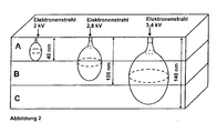
- Figure 2 schematically outlines the depth effect of the EDX method.
- electrons are knocked out of the K or L shell of the elements of the test sample.
- these electrons only have a certain range.
- the figure outlines the range of the electron beam (also called "excitation bulb") in the three-layered pigment according to the invention.
- the atomic oxygen content based on the total content of the metal evaporated to the coating and of the oxygen, in atomic%.
- Figure 3 schematically describes the geometric arrangement in a turntable evaporation plant in a vacuum chamber.
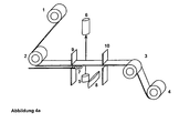
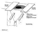
- Figure 4a shows the schematic representation of a belt system with an evaporation source, which in the vacuum chamber of Figure 3 (Without turntable device) is arranged.
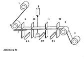
- Figure 4b shows the schematic representation of a belt system in the coating of a belt-shaped substrate with three evaporation sources.
- Figure 5 shows how in principle the three layers A, B and C can be represented by stepwise vapor deposition.
- the band will be after the Coatings A and B are each rewound in order to be able to realize both the individual layers and the complete layer sequence ABC. This procedure is recommended especially when using different metals for A or B or C.
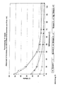
- Figure 6 shows the characteristic course of the oxygen content as a function of the layer thickness, which was determined by EDX methodology.
- Figure 7 exemplifies the Schichtdicken- or oxygen profile, determined by the ESCA method, in the event that the metals to be evaporated for the layers A, B and C are identical.
- Figure 8 exemplifies the Schichtdicken- or oxygen profile, determined by the ESCA method, for the case that the metal used for the layers A and C is the same, but not equal to B.
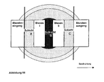
- Figure 9 shows schematically the image of the base area of a belt-shaped substrate and the intensity distribution of an evaporator cone on this band-shaped substrate with two concentration ranges, in this example, the area with the highest concentration of metal atoms and the lowest concentration of oxygen atoms in the center and is shown in black.
- This inner area is surrounded by an outer, hatched checkered area in which the concentration of metal atoms is lower and the concentration of oxygen atoms is higher than in the inner area.
- the relative expansion of these two regions to each other can be influenced by the arrangement of the oxygen-releasing oxygen source laterally of the metal evaporator source.
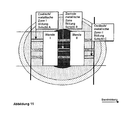
- Figure 10 shows how starting from the in Figure 9 represented intensity distribution by arrangement of covering devices, such as the illustrated panels I and II, above the band moving in the direction shown, layers with defined and substantially homogeneous contents of metal and oxygen atoms can be superimposed on the tape.
- the layers A and C have the same composition and are largely oxidic.
- Layer B is largely metallic.
- Figure 11 shows the preparative shielding of a band-shaped substrate by horizontal and vertical diaphragms I and II, which ultimately produce the coating of the individual layers A, B and C as well as the entire layer sequence ABC simultaneously with the metallization.
- the layers A and C are largely oxidic and the layer B is largely metallic.
- Figure 12 shows by way of example, the colorimetric representation of inventive metallic gold-colored, blue, violet and red effect pigments in the a *, b * color space and the color-saturating effect of the oxide-containing layers A and C compared to layers A and C with a lower oxide content.
- Figure 13 shows by way of example the enhancement of the chroma with gold-colored and blue metallic effect pigments by the higher oxide content in the layers A and C.
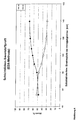
- FIG 14 the brightness values are shown graphically over different angles. This illustration is intended to underline the mirror-like nature of the effect pigments according to the invention.
- Figure 15 shows an alternative arrangement Figure 9 , In contrast to the arrangement according to Figure 9 the gas inlet is arranged centrally above the evaporation source 2.
- Figure 16 shows an inverse arrangement of the vapor-deposited layers for arranging the layers according to FIG Figure 10 , wherein in layer A and C, the content of oxygen is less than in layer B.
- the layers A and C are largely metallic and the layer B largely oxidic.
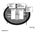
- Figure 17 shows an inverse arrangement of the evaporated layers for arrangement according to Figure 11 , wherein in layer A and C, the content of Oxygen is lower than in layer B.
- the layers A and C are largely metallic and the layer B largely oxidic.
- the layer structure of an inventive embodiment of the pigments of the invention is in illustration 1 illustrated in more detail.
- the content of oxygen in the layers A, B and / or C is within the limits specified in claim 1. Accordingly, the following statements apply correspondingly to higher or lower contents of oxygen in the layers A, B and / or C, as indicated in claim 1 respectively.
- All layers are preferably distinguished in each case by having a largely homogeneous, preferably homogeneous, distribution of metal atoms and oxygen atoms. It is therefore preferable within each layer over the layer thickness and width, no gradient of metal or oxygen atoms measurable by the methods of measurement described below.
- the high oxygen content is largely not due to the formation of superficial metal oxide layers, which can spontaneously arise on some metals in contact with air or another source of oxygen.
- the metallic effect pigments provided according to the invention are and act metallic to a viewer.
- the layers A and / or C of the pigments according to the invention are in the illustrated variant of the invention designed so that they show by an increased oxide content of 25 to 58 atomic% oxygen a more transparent appearance than pure metal layers at the same layer thickness.
- these layers are not pure oxides, which are usually completely transparent.
- the layers A and / or C preferably independently contain at least one metal M A and / or M C selected from the group consisting of aluminum, magnesium, chromium, silver, copper, gold, zinc, tin, manganese, iron, cobalt , Nickel, titanium, tantalum, molybdenum, their mixtures and their alloys.
- Preferred metals for M A and / or M C are aluminum, silver, copper, chromium, iron or mixtures or alloys thereof. Aluminum and / or chromium have proven to be particularly suitable.
- the layers A and / or C of the metallic effect pigments according to the invention preferably have a largely metallic character.
- the layer B preferably has a substantially oxidic character.
- the metallic character of the layers A and / or C may be more pronounced.
- the two outer layers are colorless dielectrics, these are i.d.R. optically not effective.
- the layers A and / or C of the effect pigments of the invention are optically active.
- the color impression is changed for a viewer.
- an optical interaction occurs between the central layer B and the outer layers A and / or C, whereby the color impression is produced in the viewer.
- the high oxygen content in the layers A and / or C of the metallic effect pigments according to the invention is attributable to the formation of oxides and / or suboxides in addition to purely metallic fractions.
- structural structure layers A and / or C have been clarified in the last detail which structural structure layers A and / or C have.
- Electron diffraction studies show two distinct diffuse rings which can be assigned to metal and metal oxide in layer A and / or C. These results show that layer A and / or C contains different phases of metal and metal oxide in a very finely divided form, preferably in the nanometer range. In this case, the average size of these nanoparticles is less than about 40 nm, preferably less than 30 nm, more preferably 20 nm and more preferably less than 10 nm.
- a layer having such structures is referred to as largely metallic in the context of this invention.
- the layers A and / or C of the metallic effect pigments according to the invention are largely homogeneously composed in the sense of this invention.
- layers A and C pure, stoichiometric oxide layers are layers A and C pure, stoichiometric oxide layers.
- the layer B correspondingly contains metal and metal oxide in finely divided form.
- the metallic effect pigments according to the invention have novel optical properties.
- the color intensity of the effect pigments increases.
- very high light-dark flops can be realized, which were previously not accessible in this strength and color intensity with an effect pigment.
- the layers of the metallic effect pigments of the invention which are preferably homogeneously composed of oxygen and metal, have good weather stability and good UV and condensation water stabilities, etc.
- the two optically active layers A and C of the effect pigments according to the invention together have an average content of oxygen of 30 to 57 atom% and particularly preferably 35 to 56 atom%.
- metals with the oxidation state + III such as aluminum or chromium, differ substantially in their respective inherent color on metallic surfaces.
- metals with the oxidation state + III are mainly deposited as metal oxides and lose their largely metallic character.
- the average content of oxygen is O A , based on the total content of M A and O A in the layer A, and the average content of oxygen O C , based on the total content of M C and O.
- C in the layer C independently of each other in a range from 25 to 58 atom%, preferably 30 to 57 atom% and particularly preferably from 35 to 56 atom%.
- the two layers preferably both have a largely metallic character, and the associated advantages are particularly evident overall in this effect pigment according to the invention.
- a single effect pigment In order to be able to determine the oxygen content within a single layer A and / or C, a single effect pigment must be analyzed by suitable focusing by the methods given below. In order to determine an average value for all effect pigments, these measurements should be carried out on at least 5, preferably at least 10, individual pigments and then an average value should be formed.
- only one of the two layers A or C has an average oxygen content O A / C , based on the total content of M A / C and O A / C , in the range of 0 to 58 atom%.
- the oxygen content of the other layer may be higher or lower than this range, but the average oxygen content of both layers is within the range of the invention.
- one of the two layers in this embodiment has a more metallic or rather oxidic character than the one other. If a layer has an oxygen content of less than 25 atomic%, the layer thickness should be selected so that the layer is optically still partially permeable in order to be able to participate in interference phenomena in this way.
- the central layer B of the multilayer metallic effect pigment according to the invention can have very different oxygen contents.
- the average oxygen content is 0 to 77 atom%, preferably 0 to 66 atom%, preferably 0 to 58 atom%, based on the total content of M B and oxygen in the layer B.
- the layer B is a metallic layer having an average oxygen content of 0 to 25 atom%, preferably from 0 to 15 atom% and particularly preferably from 0 to 10 atom%.
- the layer B has a metallic character. It therefore acts i.d.R. as a metallic reflector. Incident light can lead to attractive optical impressions by interaction of the plane-parallel oriented effect pigments according to the invention by the optical interaction of the layers A and / or C with the layer B due to interference phenomena.
- the layer thickness of the layer B is preferably in the range from 10 to 200 nm, preferably from 20 to 150 nm, more preferably from 40 to 125 nm, even more preferably from 50 to 100 nm.
- these metallic layers are optically opaque and metallically reflective.
- the visual appearance of the pigments is brought about by the interaction of the layer A and / or layer C and layer B.
- these layers show an increasingly transparent appearance with darkening of coloration.
- the metal layer is still strongly absorbing, but can not develop the high reflectivity of a metal reflector.
- the visual appearance of the pigments is effected in this case by the optical interaction of all layers A, B and C.
- the average oxygen content of the layer B is 25 to 58 atom%, preferably 30 to 57 atom% and particularly preferably 35 to 56 atom%.
- the layer B preferably has a largely metallic or oxidic character and preferably has a layer thickness of 50-2000 nm.
- this layer B has a largely metallic character analogous to the layers A and / or C.
- the layer thickness of the layer B is preferably in a range of 10 to 200 nm, preferably 20 to 150 nm, more preferably 40 to 125 nm, still more preferably 50 to 100 nm.
- the layers A, B and / or C may be different from each other.
- the layers A and B are different either with respect to the metal and / or with respect to the oxygen content, as stated above.
- the central layer B is substantially oxidic and the layers A and C applied to the central layer B are substantially metallic.
- the central layer B is substantially metallic and the layers A and C applied to the central layer B are substantially oxidic.
- the layer B can also assume a largely oxidic character.
- both layers A and C have a largely metallic character, each having an average oxygen content of 25 to 58 atom%, preferably from 0 to 25 atom%, more preferably 0 to 15 atom%, especially preferably have 0 to 10 atom%. In this case, they are effect pigments with a Fabry-Perot structure.
- the layer thickness of the layer B can be varied in the case of substantially oxidic layers of 50 to 2000 nm, preferably from 100 to 1000 nm and particularly preferably from 150 to 800 nm. At low layer thicknesses, largely monochrome metallic effect pigments are obtained, and at higher layer thicknesses, effect pigments with color flops are obtained.
- the effect pigments according to the invention have a stronger color saturation. This is probably due to the special properties of the outer layers A and C.
- the central metallic layer B preferably contains at least one metal selected from the group consisting of aluminum, chromium, silver, copper, gold, zinc, tin, manganese, iron, cobalt, nickel, titanium, their mixtures and their alloys ,
- Preferred metals are aluminum, silver, chromium or mixtures or alloys thereof.
- the metal M A and / or M C is substantially chromium and in the layer A and / or C, the average content of oxygen O A and O C is independently in the range from 35 to 48 Atomic%, based on the respective total content of chromium and oxygen in the layer A or C. It has been shown that pigments with external chromium / chromium oxide layers as layer A and C are corrosion-stable effect pigments. If, according to further embodiments, the middle layer B is silvery reflecting (eg of Ag or Al in corresponding layer thicknesses), depending on the layer thickness of the layers A and C, a color impression of light gold, gold, brown, red, violet, blue up to turquoise.
- the metal M A and / or M C is substantially aluminum and in the layer A and / or C is independently of each other, the average content of oxygen O A and O C in the range of 30 to 55 atom% , based on the respective total content of aluminum and oxygen in the layer A or C. It has been found that pigments with external aluminum / aluminum oxide layers as layer A and C are inexpensive effect pigments to be produced, depending on the layer thickness of the layers A and C have an extremely strong brightness flop. If according to further embodiments, the middle layer B is silvery reflective (eg of Ag or Al in corresponding layer thicknesses), one also obtains depending on the layer thickness of the layers A and C a color impression of light gold, gold, brown, red, purple, blue to turquoise.
- the middle layer B is silvery reflective (eg of Ag or Al in corresponding layer thicknesses)
- the metal may be present in any layer, for example in the aforementioned layers A, B and / or C, as an alloy or mixture of different metals.
- a metal having a purity above 99.0% by weight is used in each layer A, B and / or C.
- the layers A, B and / or C may be the same or independently different with respect to the metal or metals used.
- the layers A, B and / or C can then differ from one another, for example, with regard to the proportion of oxygen in atomic% and / or the layer thickness.
- the layers A and C have a comparable, more preferably an identical, chemical composition, wherein more preferably the layers A and C additionally have an identical layer thickness.
- the chemical composition of the Layer B is different from layers A and / or C.
- the layers A, B and C are arranged directly following one another.
- one or more further layers may also be located between the layers, for example between layer A and layer B.
- the optical mode of action of the layers A and / or C depends above all on the type of metal, the layer thickness and the oxygen content.
- the layer thickness of the layers A and / or C is preferably independently from 10 to 250 nm and particularly preferably from 40 to 150 nm.
- the average layer thicknesses of A and C are substantially the same thickness.
- both the layer thickness of the central layer B and / or the layer thickness of the layers A and / or C can be varied.
- only the layer thickness of the central layer B of the effect pigment according to the invention can be changed, for example in a range from 10 to 200 nm, and the layer thickness of the layers A and / or C can be kept constant.
- the colored metallic effect pigments according to the invention preferably have an average mean pigment thickness of from 30 to 550 nm and more preferably from 50 to 300 nm.
- the pigment thickness is essentially determined by the layer thicknesses of the coloring layers A and / or C and the, preferably in the range of 10 to 200 nm, layer thickness for B.
- the layer thickness B does not have a color-producing effect above 20 nm. Above about 40 nm layer thickness and one Oxygen content below 15 atomic%, the layer B acts as an opaque metallic reflector. In this case, the coloring of the metallic effect pigment is effected only by the layer A or C and the layer B.
- the layer thicknesses of the individual layers of the effect pigment according to the invention can be determined, for example, by the person skilled in the art by means of SEM images on the basis of cross-section recordings. It is important to ensure that the cross-sections of effect pigments, which are oriented substantially parallel to a defined plane, are performed. This is necessary to avoid measurement errors caused by "tilted" pigments.
- the specific oxygen content in this invention the effect pigments according to the invention are each preferably determined by means of the ESCA method (e Lectron s pectroscopy for c hemical a nalysis) or Auger spectroscopy in combination with sputtering.
- ESCA method Lectron s pectroscopy for c hemical a nalysis
- Auger spectroscopy in combination with sputtering.
- a depth profile of the average element composition along the thickness of the pigments can be created for the effect pigments. It can be differentiated between the oxygen content of the surface and the interior of the pigment.
- the Schichtdicken- or oxygen profile can also be displayed very well. To illustrate this is on the Figure 7 pointed.
- Figure 7 represents the layer thickness oxygen profile of the metallic effect pigment prepared according to Inventive Example 9, which was obtained by measurement with the ESCA method and sputtering.
- This effect pigment is a three-layered pigment having the following layer sequence: A: oxidic Al; B: metallic Al; C: oxidic Al.
- A oxidic Al
- B metallic Al
- C oxidic Al.
- A oxidic Al
- B metallic Al
- C oxidic Al
- the maximum is always selected within a region to be assigned to a layer. If a maximum plateau sets in, this is used to determine the oxygen or metal content.
- the skilled person is able to make the right assignment here.
- This method can also be performed on individual pigments.
- the incoming UV light is focused on a single pigment plate and measured accordingly.
- the pigments can be characterized in advance by means of overview photographs by means of electron emission, and the focusing can be controlled accordingly. In this case, at least five individual pigments must be analyzed in order to obtain a representative mean value.
- a constant metal / oxygen composition is determined during the measurement of individual pigments within a layer, preferably the outer layer, this is a largely homogeneous composition of this layer in the context of this invention. However, this includes any inhomogeneities that can not be determined by this measurement method, with a.
- the oxygen content of the layers can also be determined by further methods. For example, it can be determined by means of EDX analysis (energy dispersive X-ray analysis).
- EDX analysis energy dispersive X-ray analysis
- Preferably used here is a device which is integrated into an electron microscope, for example the EDAX Genisis, Version 3.60, Fa. EDAX.
- the imaging electron beam of the electron microscope penetrates a little way into the sample surface and gives off its energy to the atoms located there. Due to the high energy of the beam electrons, electrons are knocked out of the near-nuclear shells (K or L shell) of the excited atoms. This process arises from two different mechanisms X-rays. The strong deceleration of the electrons produces a continuously distributed X-radiation, the Bremsstrahlung, and the replenishment of the shells by outer electrons produces a discrete X-ray spectrum due to associated emission processes. This results in the characteristic line spectrum of the atom, which allows a clear identification of the elements.
- the kinetic energy of the electron beam has to be adapted to the elements to be analyzed. However, the penetration depth of the electron beam into the material to be examined depends on its energy.
- the electron beam penetrates into the sample in an intensity distribution which has a pear-shaped structure and is also called an excitation bulb.
- the kinetic energy must be only a few keV. Therefore, in the case of heavier elements, consequently, must be at the suggestion of the higher Dished shells. The analysis must then be done via the evaluation of the L or M lines of the elements.
- the analysis of thin-layered, platelet-shaped pigments is as follows:
- the EDX measurement unit is calibrated prior to analysis using appropriate, commercially available standards according to the manufacturer's instructions.
- the layer thickness of the layer to be examined is to be determined by means of electron microscopic images.
- An elemental analysis at a higher voltage of approx. 10 to 20 kV provides information on all elements present in the examined sample as well as additional elements in the underlying substrate.
- the electron energy is determined by means of a Monte Carlo simulation (preferred: program: EDAX Flight-E, Version 3.1-E), in which the layer volume is completely filled by the penetrating electron beam, but not yet penetrated becomes. In this case, the excitation bulb has the largest volume.
- the next step is to determine if and if so which X-ray lines are excited at this beam energy. Eventually the kinetic excitation energy has to be adapted to the spectral lines.
- a first test measurement with the parameters determined in this way must be carried out and analyzed. If X-ray lines of substrate elements can be detected in the spectrum, the set beam energy is too high and must be corrected.
- the penetration depth into the layer of the pigment can be increased by gradually increasing the excitation energy of the electron beam (the "excitation bulb"), as in FIG Figure 2 shown schematically, can be achieved.
- the penetration depth of the electron beam is set in each case and the oxide content is determined.
- the deeper layers can also be included in the analysis of the oxygen or metal content.
- Figure 6 the layer thickness and oxygen profile of effect pigments prepared according to Example 10 according to the invention are shown.
- This method can be used very well for determining the oxygen content in the layers A and / or C.
- the analysis of individual layers can be performed if this method is also combined with sputtering techniques.
- the excitation energy of the electron beam must be optimized for each individual layer.
- the three-layer structure with the outer layers having a high oxygen content causes the metallic effect pigments according to the invention overall to behave rather brittle in terms of their mechanical properties, comparable to oxides or glasses.
- PVD metal pigments Compared to the known PVD metal pigments, they thus have application advantages.
- Conventional PVD metal pigments tend to roll due to their thinness and ductility of the metal. Although they can cling perfectly to a substrate because of their flexibility, but in an application after curing of the binder always a small proportion of the pigments deformed, in extreme cases even be "rolled up". This phenomenon is accompanied by losses of optical quality.
- the ability to roll up is particularly troublesome in the manufacturing process of the pigments after peeling off the film. After the subsequent comminution of the pigments, fewer pigments are rolled up, however, the effect is still partially present and may interfere later in the application.
- these pigments are mechanically labile, which manifests itself for example in a sensitivity to the action of strong shear forces.
- the desired mechanical rigidity is realized by the multilayer structure and also the high oxygen content of the outer layers A and C in the case of one embodiment according to the invention.
- the crushed pigments do not curl up and show along their longitudinal extent a very homogeneous appearance with smooth surfaces without undulations or bulges.
- the high oxygen content of the layers A and C and optionally also B effects with regard to the mechanical properties of a largely glass or ceramic stiffness of these layers. Therefore, these pigments can be excellently comminuted after peeling off from the film.
- the result is effect pigments with very smooth break edges. This has an advantageous effect on the optical properties of the pigments, since due to the smooth break edges lower scattering centers for the incident light are present.
- the effect pigments according to the invention are always platelet-shaped.
- Their longitudinal extent, expressed by the D 50 value of the cumulative weight distribution, is in the usual ranges from 2 to 250 ⁇ m, preferably from 5 to 150 ⁇ m and particularly preferably from 7 to 50 ⁇ m.
- the size distribution is usually measured by laser diffraction methods.
- the metallic effect pigments according to the invention have form factors of from 4 to 8,500, preferably from 10 to 5,000 and particularly preferably from 20 to 1700.
- the form factor is defined as the ratio of the d 50 value of the cumulative cycle cumulative size distribution to the mean thicknesses of the platelet-shaped pigments.
- the effect pigments according to the invention surprisingly have an extraordinarily high color saturation or a strong chroma and in many embodiments a strong brightness flop. This can be determined by means of squeegee prints.
- the squeegee prints are made in preferably conventional, i. anhydrous coating systems without the addition of further effect and / or color pigments or matting agents.
- Particular preference is given to using nitro lacquers, such as, for example, the commercially available nitro lacquer. Renger Erco bronze mixed paint 2615e; Fa. Morton.
- the concentration of the effect pigment should be high enough to obtain an opaque doctor draw and depends on the type of metal, the metal content and the layer thickness (see also Table 5).
- the pigments according to the examples according to the invention and in particular the gold-colored pigments show a very strong brightness flop due to the oxide incorporation in the outer layers.
- the flop values or flop indices of the effect pigments according to the invention are in the range from 30 to 70, preferably from 35 to 65 and particularly preferably from 40 to 60.
- the effect pigments of the invention appear relatively bright near the glancing angle, comparable to aluminum pigments produced by conventional milling processes. At steeper viewing angles, however, the brightness values drop very rapidly and already reach values close to black coatings at 45 °. This results in such extremely high flop values.
- High-gloss aluminum pigments obtained by PVD processes which represent the most brilliant effect pigments to date, are known to have flop values in the range of 20 to 30 in corresponding applications.
- the flop values of the effect pigments according to the invention are generally significantly higher but partly overlap those of pigments known from the prior art.
- the brightnesses L * 45 ° are used as a measure.
- the L * 45 ° values of the effect pigments according to the invention are in the range from 1 to 25, preferably from 1.4 to 20 and particularly preferably from 1.7 to 12 brightness units. These very low values prove the strong flop in the dark.
- Known metallic PVD pigments have L * 45 ° values of over 35.
- the metallic effect pigments according to the invention have a high color saturation, which is reflected colorimetrically in a chroma value.
- the chroma measured at a differential angle of 15 ° is more than 20, preferably more than 30, and more preferably more than 40 units.
- the metal M A of the layer A and the metal M C of the layer C of the same kind can be produced particularly easily, as explained below in more detail.
- the metals M A of the layer A, M B of the layer B and M C of the layer C of the same kind are same kind.
- the average layer thicknesses of the layers A and C are substantially equal. This refers to deviations of the average layer thicknesses of A and C of up to 10%. If these layers have an approximately identical layer thickness and, moreover, are of the same type, then these are symmetrical metallic effect pigments. These produce in an application over particularly pure and clear color effects. Metallic effect pigments having a symmetrical structure are preferred according to the invention.
- the colored metallic effect pigment is characterized in that the metal M A and / or M C consists essentially of chromium and has an average content of oxygen of 35 to 48 atom%, based on the total content of chromium and oxygen, has.
- the metal M B in these embodiments is preferably made of aluminum and / or silver.
- the colored metallic effect pigment is characterized in that the metal M A and / or M C consists essentially of aluminum and has an average content of oxygen of 30 to 55 atom%, based on the total content of aluminum and oxygen, has.
- the metal M B in these embodiments is preferably made of aluminum or silver.
- a further preferred embodiment of the colored metallic effect pigments is given here by the layer sequence oxide-Al / Al / oxidic-Al, which is characterized in that the metal M A is identical to metal M B and identical to metal M C.
- the mode of action of the outer oxide aluminum layers is similar to that of the Cr oxide layers of variant A described above. The same shades can be achieved.
- Gold shades of light gold (layer B: aluminum) or silver beige (layer B: silver) to very intense reddish gold are produced in a layer thickness range of 10 nm-60 nm for the oxidic Al layers.
- the intermediate metallic layer B has in each case a metal content of 70 to 100 atomic%, based on the content of metal and oxygen in the layer B, where M B may be the same or different from M A.
- the metal M B in the layer B in the preferred embodiments, aluminum and / or silver is used, wherein the oxygen content is preferably in a range of 30 to 0 atom%, more preferably less than 25 to 0 atom%, still more preferably of less than 20 to 0 atom%, even more preferably less than 10 to 0 atom%, in each case based on the metal and oxygen content in the layer B.
- the metal content of layer B for aluminum and / or silver is preferably 70-100 atom%, based on the aluminum or the silver and any oxygen present in the layer B.
- the central Layer B below the said metal content for silver or aluminum, the central Layer B to be transparent.
- pigments according to the invention in particular for use in water-based paints or water-based printing inks, they can optionally be coated with a corrosion protection layer, preferably enveloping.
- the outer layers A and C are made of aluminum
- a chromating based on that in the EP 0 259 592 B1 disclosed methods are carried out.
- a treatment of the pigment surfaces with vanadium and / or molybdenum compounds and a combination of these methods can be carried out.
- the pigments according to the invention can also be coated with polymers or metal oxides.
- the metal oxides preferably include SiO 2 , boron oxides, aluminas, molybdate, vanadates and include their hydroxides and hydrated oxides or mixtures thereof.
- the, preferably enveloping, corrosion protection layer comprises SiO 2 or consists of SiO 2 .
- the SiO 2 layer is applied to the effect pigment enveloping with sol-gel methods.
- the effect pigments protected from corrosion with a corrosion layer according to the invention may additionally also have organic-chemical surface modifications, such as, for example, silanes, titanates or aluminates.
- the organic chemical surface modifications may cause compatibilization with the surrounding application medium, for example the binder system of a paint or a paint.
- such an organic-chemical post-coating can enable a chemical bond to binders of paints or inks, thereby enabling covalent bonding of the effect pigments according to the invention.
- a covalent attachment of the effect pigments to the binder system increases the condensation resistance and mechanical resistance of the coating medium, for example of paints and varnishes, after curing.
- the process used to prepare the effect pigments of the present invention are always PVD processes, i. that the individual layers, in the case of a three-layer system, the layers A, B and C, by PVD method successively and preferably applied to each other.
- the dispersion is preferably also present in an organic solvent.
- the proportion of organic solvent in the dispersion is at least 70% by weight.
- the effect pigments according to the invention can also be present in a more concentrated form, for example as a paste.
- the solvent content is up to 60 wt .-%, preferably up to 50 wt .-%, based on the metallic effect pigment paste.
- the metallic effect pigments according to the invention can also be present in a compacted form as pellets, granules, tablets, sausages, briquettes, etc., wherein the solvent content is preferably less than 10% by weight, more preferably between 3 and 8% by weight, in each case is present on the weight of the compacted form.
- Metal vapor deposition can be accomplished by known techniques such as electron beam technology or resistance or radiation heated processes. In these known processes, the metals are placed in and evaporated from corresponding evaporators, the metal vapor being deposited on a mobile or immobile substrate.
- the thickness of the outermost metal layers A and / or C may be controlled during application by transmission measurements.
- the transmissions are mostly due to the partially oxidic nature of Film layer lower than in the evaporation of pure metals.
- the control of the layer thickness of the central layer B can be done for example via online sheet resistance measurements.
- this alloy is produced either from separate evaporators, for example by flash evaporation, jet stream blowers or the like, by simultaneous condensation of the metals or by suitable evaporation methods such as sputtering or electron beam technology.
- the movable substrate may consist of polymer films, such as polyterephthalate, or a metal strip, which is preferably a circulating metal strip.
- the oxygen in the sputtering step may be provided by a variety of possible process variants.
- Pure oxygen is preferably fed into the vacuum chamber, since finer metallic phases or finer metal oxide phases are formed, as a result of which the color impression of the metallic effect pigments can be more finely controlled.
- the water may have atmospheric origin or come from a water reservoir.
- hydrate compounds come into question.
- the hydrate compound must be sufficiently volatile on its own, in order not to sublime under the existing vacuums.
- the hydrate compound if necessary.
- steam is metered into the vacuum chamber in a controlled manner.
- water is solid under the low pressures of a vacuum coating chamber. Therefore, the water must be sublimated by a suitable heat source. This can be, for example, in the evaporator sources in a resistance-heated metal evaporation, through which a not inconsiderable heat is generated.
- oxygen can originate from the preferably mobile substrate, for example a movable film, onto which a release coat and then the metal is subsequently vapor-deposited.
- the oxygen can also be provided by any combination of these process options.
- the vacuum pressure at step a) is relatively high.
- the vacuum pressure is preferably from 2 ⁇ 10 -4 to 1 ⁇ 10 -1 mbar, particularly preferably from 3 ⁇ 10 -4 to 1 ⁇ 10 -2 mbar and furthermore particularly preferably from 4 ⁇ 10 -4 to 3 ⁇ 10 -3 mbar , Dark layers are preferably obtained at higher pressures.
- the coating is applied by means of series-connected evaporation sources.
- the individual evaporator sources VQ A , VQ B and VQ C are separated from each other or in pairs.
- the process for producing a metallic effect pigment can be further modified by separating the individual evaporator sources 8A, 8B and 8C for vaporization of the metals by means of separators such as diaphragms or walls.
- Figure 4b shows the schematic representation in the coating of a strip-shaped substrate via three evaporator sources 8A, 8B and 8C.
- the movable substrate provided with a release coat for example a release-coated film, is guided from the swelling roll 1 over the deflection rollers 2 and 3 to the roll receiver 4.
- the assembly is disposed within a vacuum chamber (not shown).
- the evaporator sources 8A, 8B and 8C are arranged, from which the metal or metals are evaporated in the direction of the movable substrate.
- the vacuum chamber is divided in this embodiment by the partitions 9-12.
- the oxygen-releasing oxygen sources may be spaced apart, for example, from the evaporator sources 8A within the Partitions 9 and 10 and to 8C within the partitions 11 and 12 are arranged. If desired, oxygen sources may also be arranged at a distance from the evaporator source 8B. In particular, the distance of the oxygen sources to the respective evaporator and to the movable substrate is an important parameter.
- the quartz measurement 7 can be used to control the evaporation rate and, via the transmission measurement, the layer thickness of the vapor-deposited film.
- the method illustrated is continuous; the movable substrate, preferably a release coated strip of tape, is passed through the vacuum chamber at a constant rate.
- the layer thicknesses of the layers A, B and C can be adjusted by the evaporation rate and / or the distance of the evaporation source to the movable substrate.
- the layers A and C required for the colored metallic effect pigments can, for example, be realized by a greater distance of the evaporator sources 8A and 8C from the movable substrate, for example circulating or moving strip, if appropriate in combination with the selected diaphragm arrangement, in order to obtain smaller layer thicknesses. Also, the heating powers and thus the evaporation or vapor deposition rates of the evaporator sources can be adjusted individually.
- the distance from the evaporator source 8B can then preferably be set lower than is the case with the evaporator sources 8A and 8C in order to produce the highest possible metal density or layer thickness.
- a higher layer thickness in the metallic layer B can be obtained if the heating power at the evaporator source 8B is increased or the evaporation rate is increased.
- the big advantage of this particularly preferred process variant is that the complete layer sequence of the pigment according to the invention is applied in a single coating process.
- a further preferred process variant is characterized in that M A , M B and M C are the same, in pairs the same or different from each other and from a metal evaporation source or a plurality of metal evaporation sources, a movable, substrate, preferably a circulating or moving belt in a vacuum chamber in the presence metal is evaporated by one or more oxygen-emitting oxygen sources, wherein three-dimensional concentration ranges of metal vapor and oxygen form in the vacuum chamber between the metal evaporation source, the oxygen source and the movable substrate, whereby the at least three layers A, on the movable substrate by physical vapor deposition, B and C are separated with distinguishable metal and oxygen contents in succession (s. Figure 9 ).
- the fact is exploited that in the evaporation of metals, starting from an evaporator source, respectively approximately concentric circles with different metal concentrations can be deposited on a non-movable substrate. These different metal concentrations deposited on the substrate are due to the fact that the metal atoms emitted from the evaporator source in the space between the evaporator source and the substrate form three-dimensional concentration ranges in the form of evaporation cones due to the different distances.
- Figure 9 12 schematically shows a region of high metal concentration in the form of a circular area shown in black and a region of lower metal concentration concentrically surrounding this area in the form of an annular area shown in hatched plots. This concentric concentration profile is obtained when an immovable substrate is vapor-deposited with metal from an evaporator source located below the substrate.
- a capping device such as a capping device, is provided between the metal evaporation source, the oxygen source and the movable substrate.
- an aperture, or several covering devices, such as e.g. Apertures are arranged, by which the possible formation of transition layers between the layers A, B and C are suppressed, so that the at least three successive layers A, B and C can deposit with each distinguishable levels of metal and oxygen.
- FIG. 3 is an exemplary arrangement of masking devices in the form of apertures, whereby defined regions of low metal concentration, designated as layer A, are designated by a region of high metal concentration, designated layer B, and again by a region of low metal concentration, designated layer C, is separated from each other on the substrate.
- a movable substrate for example a ribbon foil, which extends from the diaphragm entrance I to the diaphragm exit II (see Figure 10 )
- the layer A is applied first, then the layer B and finally the layer C in a continuous process.
- the transition concentrations are hidden, so that the layers A, B and C have sharp transitions.
- the at least one oxygen source in the form of water, water-emitting substances, oxygen-releasing substances and / or oxygen gas is arranged in the vacuum chamber or the vacuum chamber has one or more feeds for oxygen or oxygen-releasing substances, for example water or water vapor, on.
- the oxygen source should be positioned at a defined distance from the movable substrate and the respective evaporator source.
- oxygen-containing compounds such as oxygen or water
- the layer B may also contain oxygen in different, defined amounts. If an oxygen source is positioned very close to the evaporator source, the layer B can also be made almost completely oxidic.
- FIG. 15 An alternative variant is in Figure 15 described. Here a central largely oxidic phase is obtained by the central positioning of the oxygen source. Regions of the outer evaporation cone are deposited largely metallically.
- a major advantage of these process variants is that a three-layered metallic effect pigment can be processed in just one single pass through the belt Evaporation of metal with different oxygen concentrations in different areas of the evaporation cone can be produced.
- the layer thicknesses and the oxygen content of the individual layers can be adjusted efficiently in a surprisingly simple manner in a continuous process in one step.
- the three-layer metal film applied to the substrate for example a strip-shaped plastic film, can be stored and transported in this form.
- the three-layered metal film is removed or detached from a previously applied release layer and thereby or subsequently comminuted, for example in a chemically non-reactive organic solvent. Thereafter, the metallic effect pigments according to the invention thus obtained can be concentrated and / or washed in order, for example, to remove residues of the release selayer.
- the resulting metallic effect pigments according to the invention are provided with a corrosion protection layer, for example of plastic or metal oxide (s) such as SiO 2 and / or an organic secondary coating to apply functional groups, for example, with binders of a paint system or a color Implementation can rule.
- a corrosion protection layer for example of plastic or metal oxide (s) such as SiO 2 and / or an organic secondary coating to apply functional groups, for example, with binders of a paint system or a color Implementation can rule.
- the metal pigments of the invention are used in coatings, paints, automotive coatings, powder coatings, printing inks, digital printing inks, plastics or cosmetic formulations, especially in nail polishes.
- the object underlying the invention is also achieved by a coating agent containing metallic effect pigments according to one of claims 1 to 25.
- the coating agent is selected from the group consisting of coatings, paints, automotive paints, powder coatings, printing inks, digital printing inks, plastics and cosmetic formulations.
- the object underlying the invention is also achieved by a coated article which is provided with metallic effect pigments according to one of claims 1 to 25 or with a coating agent according to claim 35 or 36.
- the object may be a vehicle body, a facade element, a printed substrate, for example paper, cardboard, foil, etc, or an artificial fingernail.
- a turntable 2 having a V-shaped cutout rotatable about an axis of rotation 6 is provided with a polyethylene terephthalate (PET) film of 23 ⁇ m thickness, which is coated with a release coat, and placed in the vacuum chamber 5, as in FIG Figure 3 shown, arranged.
- the release coat consists of acetone-soluble methyl methacrylate resin and was pre-screened in a separate step applied.
- the fixed aperture 3 which also has a V-shaped cutout arranged.
- the PET film is provided on the evaporator source 1 side facing the release coat (release layer).
- the quartz crystal 4 protruding into the V-shaped cutout of the diaphragm 4 was used to determine the deposited amounts of metal.
- the vacuum was generated by two rotary pumps (Edwards) and a diffusion pump (Varian).
- the metals used were each evaporated by resistance heating.
- the mass assignment was controlled on the quartz oscillator (model FTM7, Edwards), on the required heating power of the metal to be evaporated.
- the evaporation process was controlled so that a constant mass occupancy of the quartz crystal 4 (s. Figure 3 ) during the coating. Coating time and chamber vacuum were kept constant during the coatings.
- oxidic metal coatings of layers A and C of the examples according to the invention served as oxygen source with water-soaked cardboard pieces that were placed in the vacuum chamber before evacuation.
- the oxygen partial pressure for the respective layers was controlled via the constantly set chamber vacuum, which can be seen from Table 1.
- the process data (mass change on the quartz oscillator, chamber vacuum) can be recorded during coating.
- the vapor deposition rates recorded on the quartz crystal per second were added up in the aperture, depending on the coating time. Using a conversion factor that takes into account the density of the deposited material, it is possible to calculate the layer thickness or mass occupation of the respective layers.
- the vacuum chamber was vented, removed the metallized PET film and peeled the coating of the PET film in a separate release unit with acetone.
- the coating was separated from the film by dissolving the release coat layer.
- the separated layer packets were filtered off, and the resulting filter cake was completely washed with acetone from the release coat, transferred to a pigment suspension and comminuted to the desired particle size.
- Inventive Examples 5 and 6 were prepared by the same procedure. In contrast to the inventive examples 1-4, however, aluminum was used for layer B instead of silver. Furthermore, it was dispensed with an oxygen source, resulting in a lower oxide content in the layers A and C. In these examples, oxygen was incorporated to a lesser extent in the outer Cr layers, which is due to the distance between substrate 2 (see FIG. Figure 3 ) to the evaporation source 1 (45 cm) was favored.
- Inventive Examples 7 and 8 were also prepared in three coating steps, but with a PVD tape system, as in Figure 4a is shown schematically. It was in three passes successively with a first layer A of oxide-containing Cr, with a second layer B of aluminum (Example 7) or silver (Example 8) and finally with a third layer C of oxide-containing Cr coated. After coatings A and B, respectively, the coated tape was rewound to obtain the desired coating sequence.
- Comparative Example 9 was carried out.
- aluminum was used as the metal to be evaporated for the layers A, B and C.
- the comparative example 20 was carried out in the same way.
- an iron-chromium alloy was produced by means of electron beam evaporators as the metal to be evaporated for the layers A and C.
- Oxygen incorporation into layers A and C was carried out using a gas flow regulator (Mass Flow Controller) from MKS Figure 15 ,
- MKS Figure 15 Mass Flow Controller
- Example 21 The coating for Example 21 was carried out in the same manner as Example 20.
- titanium was evaporated by means of electron beam evaporation.
- PET polyethylene terephthalate
- the release coat consisted of acetone-soluble methyl methacrylate resin and was applied in advance in a separate step.
- the vacuum was, as stated above, also generated by means of two forepumps and a diffusion pump.
- the process parameters are listed in Table 2 and Table 3.
- the film was agitated at the belt speeds shown in Tables 2 and 3, respectively.
- On the moving film layers A, B and C of the specified metals were deposited by vapor deposition. Evaporation of the metals was done using resistance heating for Examples 7-9 and by electron beam method (electron beam evaporator from Telemark Model 272) for Examples 20-21.
- the mass occupation was determined by means of a quartz crystal measurement, as in Figure 4a illustrated (model FTM7, Edwards), controlled and controlled the layer thickness on the heating power and belt speed.
- oxidic metal coatings A and C of the examples according to the invention served as oxygen source water-soaked cardboard pieces that were placed in the vacuum chamber before evacuation.
- the oxygen partial pressure for the respective layers was controlled via the constantly set chamber vacuum (see Table 2).
- the film to be coated was used in Examples 7, 20 and 21, as in FIG Figure 5 shown schematically, prepared by suitably placed aperture during the coating operations. As a result, certain film sections were coated exclusively with only one layer A, B or C and could later be analyzed separately. In the section without screens, all three layers were deposited.
- the vacuum chamber was vented, removed the metallized PET film and peeled the coating of the PET film in a separate release unit with acetone.
- the coating was separated from the film by dissolving the release coat layer.
- the separated layer packets were filtered off, and the resulting filter cake was completely washed with acetone from the release coat, transferred to a pigment suspension and comminuted to the desired particle size.
- a PVD tape method according to the invention was used in which a three-layer metal pigment was produced in only one pass.
- the entire vacuum chamber was equipped with the following oxygen sources in each case: for example 10, a constant oxygen partial pressure was generated by a constant metered addition of air into the vacuum chamber.
- wet boxes were placed to the left and right of the iris input and the iris exit, respectively (see Figure 9 ).
- Example 13 For positioning in Example 13, two boxes soaked in oxygen were brought close to the evaporation cone. Due to the radiant heat emanating from the evaporator, a high sublimation flow of water from the two water-soaked cartons into the metal cone was generated.
- Figure 10 respectively.
- Figure 16 shows in a schematic plan view (from the perspective of the evaporator source), a diaphragm arrangement between the evaporator source and coating tape.
- the coating tape could be subdivided into three separate coating zones, in each of which only layers A, B and C were formed.
- Examples 11 and 13 in contrast to Examples 10, 22, 23, 24 (see plan view schematic Figure 10 ) dispensed with a separation by screens in three coating areas.
- PET polyethylene terephthalate
- release coat consisted of acetone-soluble methyl methacrylate resin and was applied in advance in a separate step.
- the vacuum was generated in each case by means of two forepumps and a diffusion pump, as described above.
- a single evaporator source of resistance heated aluminum was used.
- the layer thickness of the central Al layer A was controlled by the amount of Al wire fed from the outside into the vacuum chamber, the size of the central aperture, the heat output of the evaporator ceramic used and the belt speed.
- Example 22 For Examples 22, 23, 24, by means of an electron beam evaporator from Telemark Model 272, according to the process parameters of Table 3, Cr (Example 22), Ag (Example 23) and Cu (Example 24) were evaporated.
- the layer thickness of the central layers B was controlled by the respective emission currents at a constant acceleration voltage, the sizes of the diaphragm cutouts in each case for Examples 22, 23 and 24 and the respective belt speeds.
- the layer thickness for Examples 10, 11, 13 and 22, 23, 24 and the oxide content of the layers A and C was controlled by the aperture arrangement and the amount of oxygen supplied.
- the experimental parameters are listed in Table 2 and Table 3, respectively.
- the vacuum chamber was vented and removed the metallized PET film.
- the coated films of Examples 10, 22, 23 and 24 each showed four longitudinal stripes of the layers A, B and C, which differed clearly in color from the complete layer sequence A-B-C.
- the film sections of the coatings A, B and C as well as the complete layer sequence A-B-C were cut off from one another and removed from the PET film in separate detaching units with acetone.
- the pigments according to Examples 11 and 13 were prepared according to the schematic representation of the method in Figure 9 and the procedure described above, according to the process parameters in Table 2, but without the two narrow additional apertures I and II and without the longitudinal apertures.
- the composition of oxygen and metal were determined by means of EDX (device: EDAX Gemini, EDAX Incorp., USA) on the individual layers by the measuring methodology described above.
- the excitation energy of the electron beam determined the penetration depth into the pigment (cf. Figure 2 ).
- the K ⁇ line (excitation energy: approx. 0.5 keV)
- the L ⁇ line (excitation energy: approx. 0.6 keV)
- the aluminum the K ⁇ - line (excitation energy: approx 1.5 keV).
- the penetration depth of the electron beam in the sample was continuously increased.
- EDX analysis was used to investigate which elements were excited. In this way, it was possible to determine exactly from which layer thickness (or penetration depth) the elements of the respective second or third layer can be detected. For analysis, only those spectra were used which represent the signals of the first layer, the second layer and finally the third layer. In the third layer, however, signals of the first layer derived from underlying pigments were again obtained. The signals of this layer could therefore no longer be completely resolved.
- the partially overlapping peaks were analyzed for analysis by means of the proprietary software program (version 3.60) by holographic peak deconvolution analysis (HDP).
- Example 8 and Example 9 were analyzed by ESCA for their elemental composition and their metal and oxygen content.
- the pigments were taken up in acetone and dried on a glass support. In this way, a largely plane-parallel orientation of the pigments is achieved.
- the measurements were carried out with the ESCALAB 250 device from Thermo VG Scientific.
- For the excitation was monochromatic Al K ⁇ .
- X-radiation (15 kV, 150 W, 500 ⁇ m spot size).
- the transmission function of the device was measured on a copper sample.
- a "Flood Gun” with an electron energy of 6 eV / 0.05 mA beam current was used.
- the mean layer thicknesses of the samples were determined by counting a significant sample (> 20 particles) under a scanning electron microscope (SEM). Here, the azimuthal angles of the individual pigment particles relative to the observer plane were estimated and included in the calculation. Only particles that were largely perpendicular to the observer plane were measured.
- the layer structure of the pigments can be further analyzed by SEM cross sections.
- Figure 7 is the determined by ESCA / XPS measurements layer structure of the pigment according to Example 9 of the invention.
- the outer layers there is on average an aluminum concentration of 53 at.% And a corresponding oxygen concentration of 47 at.%. After a sputtering depth of about 50 nm, the aluminum signal begins to grow and the oxygen signal accordingly drops. At the maximum, the Al concentration reaches 71 atomic%.
- Example 12 (Method with Three Evaporation Sources)
- the layer thickness of the central Al layer A was controlled by the amount of Al wire fed from the outside into the vacuum chamber, the size of the central aperture, the heat output of the evaporator ceramic used and the belt speed.
- the layer thickness and the oxide content of the Cr layers A and C were controlled by the diaphragm arrangement and the variably adjustable resistance of the molybdenum vessels, as well as the amount of oxygen supplied. After completion of the coating, the vacuum chamber was vented, removed the metallized PET film and further processed as described in the other examples.
- the mean particle size is 17 ⁇ m.
- Comparative Example 16 Commercially available gold leaf.
- Comparative Example 17 Gold was sputtered onto a microscope slide in a layer thickness of about 80 nm.
- the size distribution of the pigments of Examples 1-8, 10-13, 23, 24 and the comparative examples were determined by standard crushing methods by means of conventional laser diffraction methods (Cilas 1064 device) and in the usual way from the cumulative weight distribution of the D 50 value as a measure of the mean size determined (see Table 5).
- the respective pigment was stirred into in each case 2 g of a conventional nitrocellulose lacquer (Dr. Renger Erco Bronzemischlack 2615e, from Morton).
- a conventional nitrocellulose lacquer Dr. Renger Erco Bronzemischlack 2615e, from Morton.
- the effect pigment was presented and then dispersed with a brush in the paint.
- the finished paint was applied to a doctor blade feeder with a wet film thickness of 50 microns on test cards No. 2853 from. Byk Gardner (black and white contrast paper).
- the pigmentation height was chosen so as to give a covering layer. As a result, the influence of the background is not included in the colorimetric data.
- the squeegee prints were measured colorimetrically according to the manufacturer's instructions (instrument Optronic Multiflash, Berlin). It was radiated at a constant angle of 45 ° and the CIELAB L *, a * and b * values at observation angles of 15 °, 20 °, 25 °, 45 °, 55 °, 70 °, 75 ° and 110 ° relative to the glancing angle (light source: D65).
- Figure 12 shows in a CIELAB a *, b * - representation of the colorimetric representation of inventive pigments and pigments of comparative examples.
- a gold leaf pattern (Comparative Example 16, Best Rosenobel double gold 23 3 ⁇ 4 carat, company Noris gold leaf) was measured.
- the pigments of Examples 1, 8 and 11 show metallic gold-colored effects. Accordingly, example 2 appears blue, example 3 red and example 4 violet with color flop effects.
- Comparative Example 16 (gold leaf) also shows a strong chroma, but a slight color flop (measurement angle 15 ° after 20 °) and therefore a lower color purity than the pigments according to the invention.
- Example 11 which was prepared by coating in a sputtering step, in its course shows a cling to the course of the gold leaf pattern in the yellow area (Comparative Example 16), but does not reach the chroma of the gold leaf.
- Example 8 also shows a conformance of the curve to the gold leaf pattern and also shows a much stronger chroma than the gold leaf pattern.
- the pigments of Examples 5 and 6 have a more subtle chroma.
- FIG 14 For example, the brightness values are plotted against various viewing angles of various gold colored examples and comparative examples.
- Examples 7 and 8 of the present invention and samples known in the art such as brass pigments (Comparative Example 14), variochrome (Comparative Example 15) and gold leaf pattern (Comparative Example 16) were used.
- a slide was sputtered in a sputtering process with gold and thereby mirrored (Comparative Example 17) and this measured.
- the brightness curves of Examples 7 and 8 show an extremely high drop to low values at higher viewing angles. This effect is mainly due to the high oxygen content of the outer layers A and C of these pigments. These layers have a dark color.
- the pigments Comparative Examples 14 to 16 show 15 ° higher L * values, but at higher angles do not reach the low values of the inventive examples.
- the sputtered on the slide gold appears as a gold mirror and therefore has an extremely high gloss.
- the measured brightness at 15 ° of this sample is very low, since in this case practically all incident light was reflected in the glancing angle and hardly any scattered radiation is present. Therefore, the comparatively low brightnesses of the examples according to the invention at high measuring angles appear all the more remarkable.
- the extremely strong brightness change from bright to dark of the pigments according to the invention also reflects the very high flop values (Table 5).
- Table 5 ⁇ b> Table 5: ⁇ / b> sample Layer sequence of the evaporated metal measurement methods Pigmentation level [%] D 50: [ ⁇ m] brightnesses flop Subjective color impression EDX ESCA L15 L45 L110 example 1 Cr Ag Cr 8.8 15 86.8 14.2 5.9 36 Very colorful gold-brown shiny 50 ⁇ m doctor blade Layer thicknesses [nm] 23 50 23 Example 2 Cr Ag Cr 11.3 ⁇ 17 74.8 8.9 3.0 47.7 Shiny blue into the black tipping 50 ⁇ m doctor blade Layer thicknesses [nm] 41 50 Example 3 Cr Ag Cr 9.6 ⁇ 17 45.4 4.1 1.9 53.9 Red shining into the black tipping 50 ⁇ m doctor blade Layer thicknesses [nm] 32 50 32 Example 4 Cr Ag Cr 10.2 20 44.6 3.9 1.9 53.9 Violet shining into the black tipping 50 ⁇ m doctor blade Layer thicknesses [
- TEM images were taken on selected samples (device: scanning transmission electron microscope, manufacturer: Fa. Jeol (Japan), type: 2010).
- the prepared cross section of the samples was irradiated with an electron beam of 200 KV and the structure images and the diffraction images were recorded with the aid of a CCD camera.
- the electron beam In bright image areas, the electron beam is scattered little, while darker areas are caused by a strong interaction of the electrons with the sample. It can be both scattering of dense and heavy areas as well as diffraction effects on crystal surfaces.
- the evaluation of the diffraction images allows statements about the crystallographic structure of the sample. If the electron beam strikes a single crystal, it is diffracted at the lattice planes of the crystal and produces a discrete diffraction spectrum in the focal plane of the TEM. If the area shown consists of many small, randomly oriented crystallites (polycrystalline material), concentric circles form the Debye-Scherrer rings instead of individual diffraction points. For amorphous samples, the diffraction pattern consists of diffuse rings. These structures are material-specific and documented for many substances in the literature.
- the samples were incorporated in an epoxy resin. After curing about 100 nm thick slices were prepared by ultramicrotomy and applied to TEM mesh.
- the TEM preparations were transilluminated with an electron beam of 200 kV. By imaging the focal plane, the diffraction patterns of the samples irradiated with electron beams were visualized. Here, two distinguishable rings were detected for the single layer of Example 18 as diffraction signals (CCD camera). In the sample of Example 7, sharp reflections as well as rings were detected. The position of the individual reflexes or rings is compared with characteristic diffraction constants from the literature. Table 6 shows the experimental values (only the most intense signals were evaluated), literature data and the assignments of the experimental data. ⁇ b> Table 6: Results of electron diffraction experiments ⁇ / b> sample d ( ⁇ ) measured reflex character assignment literature values there) rel.
- the ring 1 Cr 2 O 3 and ring 2 can be assigned to metallic Cr.
- the deposited Cr is present both in an extremely finely divided (nanometric) metallic form and in an oxide form.
- this layer is largely homogeneously composed, since such phases which exist at a nanometer level can no longer be resolved by the other methods (EDX, XPS).
- the metallic chromium and the oxidic chromium are also largely mixed together into a layer and are not something as two separate, successive layers, as would have detected in this case by means of the other measurement method corresponding Konzentrationsunterborge.
- Example 7 in addition to the ring signals of Example 18, sharp reflections were detected which can be assigned to the metallic aluminum of the middle layer B.
- Example 8 Beforehand, the pigment suspension from Example 8 is reacted in ethyl acetate and adjusted to 20% by weight solids content.
- Table. 7 Nail Polish Composition ⁇ / b> No. material Concentration in% by weight 1
- Inventive Example 8 (20% by weight metallic effect pigment in ethyl acetate) 20 2 Hostaphat CS 120 * 1 3 methyl ethyl ketone 20 4 methyl isobutyl ketone 20 5 CAB 381.2 9 6 Butyl acetate 98/100 30 * Stearyl phosphoric acid ester
- Example 8 The pigment suspension of Example 8 according to the invention was brought to a pigment content of 25% by weight by careful evaporation of acetone.
- the butyl acetate is introduced and the CAB powder (cellulose acetyl butyrate) added in portions with stirring.
- the components 2-4 are added in succession to the metal pigment dispersion and incorporated gently.
- Example 8 Beforehand, the pigment suspension from Example 8 is converted into isononyl nonanoate and adjusted to 20% by weight solids content.
- the result is a liquid eyeliner that leaves a gold metallic impression after application to the eyelid.
- the layers A and / or C have a substantially homogeneous chemical composition with respect to oxygen O A and / or O c or metal M A and / or M c .
- the layers A and C of the metallic effect pigment have an average content of oxygen O AC of from 30 to 57 atom%.
- the layers A and C of the metallic effect pigment have an average content of oxygen O AC of 35 to 56 atom%.
- the total content of M A and of O A is 90 to 100 atom%, based on all components of layer A, or the total content of M C and at O C 90 to 100 atom%, based on all components of the layer C.
- the layer A and / or C independently have an average thickness of 10 to 250 nm.
- the at least one metal M B is selected from the group consisting of aluminum, chromium, silver, copper, gold, zinc, tin, manganese, iron, cobalt, nickel, titanium, their mixtures and their alloys. selected.
- the layer B has a metallic character and has an average thickness of 10 to 200 nm.
- the layer B has a largely metallic or oxidic character and has an average thickness of 50 to 2000 nm.
- the entire metallic effect pigment has an average thickness of 30 to 550 nm.
- the metallic effect pigment has an average thickness of 50 to 300 nm.
- the metals M A , M B and M c are the same.
- the average layer thicknesses of the layers A and C are substantially the same.
- the layers A, B and C are arranged directly following one another.
- the metallic effect pigment is coated with a corrosion protection layer, preferably enveloping.
- the, preferably enveloping, corrosion protection layer comprises SiO 2 or consists of SiO 2 .
- the at least one oxygen source in the form of water, water-releasing substances, oxygen-releasing substances and / or oxygen gas is arranged in the vacuum chamber.
- a controlled metered addition of oxygen gas into the vacuum chamber takes place during step a) and step c) and optionally during step b).
- the coating agent contains metallic effect pigments according to the invention.
Landscapes
- Chemical & Material Sciences (AREA)
- Organic Chemistry (AREA)
- Life Sciences & Earth Sciences (AREA)
- Engineering & Computer Science (AREA)
- Materials Engineering (AREA)
- Wood Science & Technology (AREA)
- Health & Medical Sciences (AREA)
- General Health & Medical Sciences (AREA)
- Animal Behavior & Ethology (AREA)
- Public Health (AREA)
- Veterinary Medicine (AREA)
- Chemical Kinetics & Catalysis (AREA)
- Nanotechnology (AREA)
- Birds (AREA)
- Epidemiology (AREA)
- General Chemical & Material Sciences (AREA)
- Medicinal Chemistry (AREA)
- Polymers & Plastics (AREA)
- Inorganic Chemistry (AREA)
- Pigments, Carbon Blacks, Or Wood Stains (AREA)
- Laminated Bodies (AREA)
Applications Claiming Priority (2)
| Application Number | Priority Date | Filing Date | Title |
|---|---|---|---|
| DE102007034928A DE102007034928A1 (de) | 2007-07-24 | 2007-07-24 | Mehrschichtige metallische Effektpigmente, Verfahren zu deren Herstellung und Verwendung |
| PCT/EP2008/006084 WO2009012995A1 (de) | 2007-07-24 | 2008-07-24 | Mehrschichtige metallische effektpigmente, verfahren zu deren herstellung und verwendung |
Publications (2)
| Publication Number | Publication Date |
|---|---|
| EP2176359A1 EP2176359A1 (de) | 2010-04-21 |
| EP2176359B1 true EP2176359B1 (de) | 2011-11-30 |
Family
ID=39940636
Family Applications (1)
| Application Number | Title | Priority Date | Filing Date |
|---|---|---|---|
| EP08785037A Not-in-force EP2176359B1 (de) | 2007-07-24 | 2008-07-24 | Mehrschichtige metallische effektpigmente, verfahren zu deren herstellung und verwendung |
Country Status (6)
| Country | Link |
|---|---|
| US (1) | US9175166B2 (zh) |
| EP (1) | EP2176359B1 (zh) |
| CN (1) | CN101932660B (zh) |
| AT (1) | ATE535579T1 (zh) |
| DE (1) | DE102007034928A1 (zh) |
| WO (1) | WO2009012995A1 (zh) |
Families Citing this family (20)
| Publication number | Priority date | Publication date | Assignee | Title |
|---|---|---|---|---|
| DE102009006550A1 (de) * | 2009-01-28 | 2010-07-29 | Eckart Gmbh | PVD-Metalleffektpigment mit Gradient an nanoskaligen Metallteilchen, Verfahren zu deren Herstellung und Verwendung derselben |
| DE102010020507A1 (de) | 2010-05-14 | 2011-11-17 | Eckart Gmbh | Metall-Kationen und phosphor- und/oder schwefelhaltige Anionen aufweisende Metalleffektpigmente, Verfahren zur Herstellung dieser Metalleffektpigmente und Verwendung |
| DE102010032399A1 (de) | 2010-07-27 | 2012-02-02 | Eckart Gmbh | PVD-Metalleffektpigmente mit diffraktiver Struktur und Metallnanopartikeln, Verfahren zu deren Herstellung und Verwendung derselben |
| US8529876B2 (en) * | 2011-02-15 | 2013-09-10 | Basf Corporation | Pigment mixtures for cosmetics |
| EP2607432A1 (de) * | 2011-12-21 | 2013-06-26 | Merck Patent GmbH | Effektpigmente basierend auf Substraten die einen Kreisformfaktor von 1,2-2 aufweisen |
| EP2904043A4 (en) * | 2012-10-01 | 2016-05-18 | Viavi Solutions Inc | DYE COMPRISING A MIXTURE OF PIGMENTS |
| US9168209B2 (en) | 2013-03-13 | 2015-10-27 | Johnson & Johnson Consumer Inc. | Pigmented skin-care compositions |
| US9320687B2 (en) | 2013-03-13 | 2016-04-26 | Johnson & Johnson Consumer Inc. | Pigmented skin-care compositions |
| US9168393B2 (en) | 2013-03-13 | 2015-10-27 | Johnson & Johnson Consumer Inc. | Pigmented skin-care compositions |
| US9168394B2 (en) | 2013-03-13 | 2015-10-27 | Johnson & Johnson Consumer Inc. | Pigmented skin-care compositions |
| US9625398B1 (en) * | 2016-01-11 | 2017-04-18 | International Business Machines Corporation | Cross sectional depth composition generation utilizing scanning electron microscopy |
| WO2017178610A1 (de) * | 2016-04-15 | 2017-10-19 | Eckart Gmbh | Oberflächenmodifiziertes effektpigment und nagellackkomposition |
| EP3369784A1 (fr) * | 2017-03-02 | 2018-09-05 | The Swatch Group Research and Development Ltd | Pigment interferenciel basé sur un coeur métallique choisi parmit l'au, ag, pd, rh, ru, pt, os, ir et leurs alliages |
| EP3791853A1 (de) | 2017-10-18 | 2021-03-17 | ECKART GmbH | Oberflächenmodifizierte geprägte effektpigmente |
| MX2020005821A (es) * | 2017-12-06 | 2020-08-20 | Eckart Gmbh | Pigmento de aluminio pvd en forma de escamas con una encapsulacion protectora y metodo para fabricar un pigmento de aluminio pvd en forma de escamas con una encapsulacion protectora. |
| MX2019002665A (es) * | 2018-03-14 | 2019-09-16 | Viavi Solutions Inc | Metodo sin solvente para fabricar dispositivos de pelicula delgada. |
| JP2020079368A (ja) * | 2018-11-14 | 2020-05-28 | トヨタ自動車株式会社 | 光輝性顔料およびその製造方法 |
| CN109666313A (zh) * | 2019-01-16 | 2019-04-23 | 清远市绚淳环保新材料有限公司 | 一种耐腐蚀的水性彩色铝颜料的制备方法 |
| WO2022230690A1 (ja) * | 2021-04-28 | 2022-11-03 | ナトコ株式会社 | インクジェットインク、印刷物の製造方法、印刷物および金属顔料分散液 |
| CN115160831B (zh) * | 2022-06-22 | 2023-11-28 | 合肥旭阳铝颜料有限公司 | 一种具有镜面效果的水性铝颜料及其制备方法和应用 |
Family Cites Families (19)
| Publication number | Priority date | Publication date | Assignee | Title |
|---|---|---|---|---|
| US2941894A (en) | 1955-03-16 | 1960-06-21 | American Marietta Co | Metallized coating compositions |
| US2839378A (en) | 1955-04-15 | 1958-06-17 | American Marietta Co | Method of making metal flakes |
| US3438796A (en) | 1967-02-02 | 1969-04-15 | Du Pont | Aluminum-silica-aluminum flake pigments |
| US4321087A (en) | 1978-12-21 | 1982-03-23 | Revlon, Inc. | Process for making metallic leafing pigments |
| US5569535A (en) | 1979-12-28 | 1996-10-29 | Flex Products, Inc. | High chroma multilayer interference platelets |
| US4430366A (en) | 1981-02-04 | 1984-02-07 | Minnesota Mining And Manufacturing Company | Metal/metal oxide coating |
| DE3636183A1 (de) | 1986-08-27 | 1988-03-03 | Basf Lacke & Farben | Wasserverduennbare beschichtungszusammensetzungen |
| DE4217511A1 (de) * | 1992-05-27 | 1993-12-02 | Basf Ag | Glanzpigmente auf der Basis von mehrfach beschichteten plättchenförmigen metallischen Substraten |
| DE4405492A1 (de) * | 1994-02-21 | 1995-08-24 | Basf Ag | Mehrfach beschichtete metallische Glanzpigmente |
| DE4437752A1 (de) * | 1994-10-21 | 1996-04-25 | Basf Ag | Verfahren zur Herstellung von siliciumoxidbeschichteten Feststoffteilchen |
| DE69601432T2 (de) * | 1995-03-16 | 1999-10-07 | Minnesota Mining & Mfg | Schwarz-Metall wärmebildbare Transparenz-Elemente |
| JPH08333602A (ja) * | 1995-06-05 | 1996-12-17 | Toyo Alum Kk | 着色チタンフレーク、その製造方法および着色チタンフレークを含む樹脂組成物 |
| US6013370A (en) | 1998-01-09 | 2000-01-11 | Flex Products, Inc. | Bright metal flake |
| US20060118663A1 (en) | 2002-08-20 | 2006-06-08 | Steiner Gmbh & Co. Kg | Copper-based metal flakes, in particular comprising aluminum, and method for production thereof |
| CN1723250A (zh) * | 2002-12-10 | 2006-01-18 | 西巴特殊化学品控股有限公司 | 基于涂覆有SiOz(0.70≤z≤2.0)的铝的薄片形式的颜料 |
| DE50312204D1 (de) | 2003-10-10 | 2010-01-21 | Fraunhofer Ges Forschung | Verfahren zur Beschichtung von bandförmigem Material mit schwarzem Aluminiumoxid |
| DE102004002222B3 (de) * | 2003-12-23 | 2005-07-21 | Dipl.-Ing. Hilmar Weinert Vakuum-Verfahrenstechnik Gmbh | Herstellung von dünnen Plättchen aus zumindest einem dielektrischen Stoff, dünne Plättchen und Vorrichtung |
| DE102004063433A1 (de) | 2004-12-23 | 2006-07-06 | Eckart Gmbh & Co. Kg | Mehrschichtiges Effektpigment mit zentraler Absorberschicht, Verfahren zu deren Herstellung, Verwendung derselben, Beschichtungsmittel und beschichteter Gegenstand |
| EP1984460B1 (de) * | 2006-02-14 | 2012-04-11 | Eckart GmbH | Dunkle metallische effektpigmente hergestellt durch pvd-verfahren |
-
2007
- 2007-07-24 DE DE102007034928A patent/DE102007034928A1/de not_active Withdrawn
-
2008
- 2008-07-24 WO PCT/EP2008/006084 patent/WO2009012995A1/de active Application Filing
- 2008-07-24 CN CN2008801004676A patent/CN101932660B/zh not_active Expired - Fee Related
- 2008-07-24 US US12/670,007 patent/US9175166B2/en not_active Expired - Fee Related
- 2008-07-24 AT AT08785037T patent/ATE535579T1/de active
- 2008-07-24 EP EP08785037A patent/EP2176359B1/de not_active Not-in-force
Also Published As
| Publication number | Publication date |
|---|---|
| DE102007034928A1 (de) | 2009-01-29 |
| CN101932660A (zh) | 2010-12-29 |
| ATE535579T1 (de) | 2011-12-15 |
| EP2176359A1 (de) | 2010-04-21 |
| CN101932660B (zh) | 2013-10-23 |
| US9175166B2 (en) | 2015-11-03 |
| US20100196296A1 (en) | 2010-08-05 |
| WO2009012995A1 (de) | 2009-01-29 |
Similar Documents
| Publication | Publication Date | Title |
|---|---|---|
| EP2176359B1 (de) | Mehrschichtige metallische effektpigmente, verfahren zu deren herstellung und verwendung | |
| EP1984460B1 (de) | Dunkle metallische effektpigmente hergestellt durch pvd-verfahren | |
| EP2262864B1 (de) | Pvd-metalleffektpigment mit gradient an nanoskaligen metallteilchen, verfahren zu deren herstellung und verwendung derselben | |
| EP1833923B1 (de) | Mehrschichtiges effektpigment mit zentraler absorberschicht, verfahren zu deren herstellung, verwendung derselben, beschichtungsmittel und beschichteter gegenstand | |
| EP2598578B1 (de) | Pvd-metalleffektpigmente mit diffraktiver struktur und metallnanopartikeln, verfahren zu deren herstellung und verwendung derselben | |
| EP3283573B1 (de) | Perlglanzpigmente auf der basis von monolithisch aufgebauten substraten, verfahren zu deren herstellung sowie die verwendung solcher perlglanzpigmente | |
| EP0332071B2 (de) | Verfahren zur Herstellung von besonders blaustichigen Perlglanzpigmenten | |
| EP1937781B1 (de) | Farbiges effektpigment mit schicht aus diskreten metallteilchen, verfahren zu dessen herstellung und dessen verwendung | |
| EP2123721B1 (de) | Perlglanzpigmente auf Basis von feinen und dünnen Substraten | |
| DE10153196A1 (de) | Pigment mit Metallglanz | |
| EP1251152A1 (de) | Eiseneffektpigmente | |
| EP0353544A1 (de) | Goniochromatische Pigmente, Verfahren zu deren Herstellung und deren Verwendung zur Herstellung von Druckfarben | |
| DE10313978A1 (de) | Silberpigment | |
| DE102019008593A1 (de) | Mlt Kohlenstoff beschichtete BiOCl-Pigmente | |
| EP2303969B1 (de) | Mischung aus dünnen eisen- und aluminiumeffektpigmenten, verfahren zu deren herstellung und deren verwendung | |
| EP4222221B1 (de) | Verwendung einer metalleffektpigmente enthaltenden lackformulierung zum lackieren eines mit einem radarsensor und einem lidarsensor ausgestatteten fahrzeugs |
Legal Events
| Date | Code | Title | Description |
|---|---|---|---|
| PUAI | Public reference made under article 153(3) epc to a published international application that has entered the european phase |
Free format text: ORIGINAL CODE: 0009012 |
|
| 17P | Request for examination filed |
Effective date: 20100223 |
|
| AK | Designated contracting states |
Kind code of ref document: A1 Designated state(s): AT BE BG CH CY CZ DE DK EE ES FI FR GB GR HR HU IE IS IT LI LT LU LV MC MT NL NO PL PT RO SE SI SK TR |
|
| AX | Request for extension of the european patent |
Extension state: AL BA MK RS |
|
| RIN1 | Information on inventor provided before grant (corrected) |
Inventor name: GEISSLER, BERNHARD Inventor name: BLEISTEINER, JASMIN Inventor name: HERZING, WOLFGANG Inventor name: SCHNEIDER, RALPH Inventor name: FISCHER, MARTIN |
|
| 17Q | First examination report despatched |
Effective date: 20100618 |
|
| DAX | Request for extension of the european patent (deleted) | ||
| GRAP | Despatch of communication of intention to grant a patent |
Free format text: ORIGINAL CODE: EPIDOSNIGR1 |
|
| GRAS | Grant fee paid |
Free format text: ORIGINAL CODE: EPIDOSNIGR3 |
|
| GRAA | (expected) grant |
Free format text: ORIGINAL CODE: 0009210 |
|
| AK | Designated contracting states |
Kind code of ref document: B1 Designated state(s): AT BE BG CH CY CZ DE DK EE ES FI FR GB GR HR HU IE IS IT LI LT LU LV MC MT NL NO PL PT RO SE SI SK TR |
|
| REG | Reference to a national code |
Ref country code: CH Ref legal event code: EP Ref country code: GB Ref legal event code: FG4D Free format text: NOT ENGLISH |
|
| REG | Reference to a national code |
Ref country code: IE Ref legal event code: FG4D Free format text: LANGUAGE OF EP DOCUMENT: GERMAN |
|
| REG | Reference to a national code |
Ref country code: CH Ref legal event code: NV Representative=s name: FIAMMENGHI-FIAMMENGHI |
|
| REG | Reference to a national code |
Ref country code: DE Ref legal event code: R096 Ref document number: 502008005755 Country of ref document: DE Effective date: 20120126 |
|
| REG | Reference to a national code |
Ref country code: NL Ref legal event code: VDEP Effective date: 20111130 |
|
| LTIE | Lt: invalidation of european patent or patent extension |
Effective date: 20111130 |
|
| PG25 | Lapsed in a contracting state [announced via postgrant information from national office to epo] |
Ref country code: LT Free format text: LAPSE BECAUSE OF FAILURE TO SUBMIT A TRANSLATION OF THE DESCRIPTION OR TO PAY THE FEE WITHIN THE PRESCRIBED TIME-LIMIT Effective date: 20111130 Ref country code: IS Free format text: LAPSE BECAUSE OF FAILURE TO SUBMIT A TRANSLATION OF THE DESCRIPTION OR TO PAY THE FEE WITHIN THE PRESCRIBED TIME-LIMIT Effective date: 20120330 Ref country code: NO Free format text: LAPSE BECAUSE OF FAILURE TO SUBMIT A TRANSLATION OF THE DESCRIPTION OR TO PAY THE FEE WITHIN THE PRESCRIBED TIME-LIMIT Effective date: 20120229 |
|
| PG25 | Lapsed in a contracting state [announced via postgrant information from national office to epo] |
Ref country code: LV Free format text: LAPSE BECAUSE OF FAILURE TO SUBMIT A TRANSLATION OF THE DESCRIPTION OR TO PAY THE FEE WITHIN THE PRESCRIBED TIME-LIMIT Effective date: 20111130 Ref country code: SE Free format text: LAPSE BECAUSE OF FAILURE TO SUBMIT A TRANSLATION OF THE DESCRIPTION OR TO PAY THE FEE WITHIN THE PRESCRIBED TIME-LIMIT Effective date: 20111130 Ref country code: PT Free format text: LAPSE BECAUSE OF FAILURE TO SUBMIT A TRANSLATION OF THE DESCRIPTION OR TO PAY THE FEE WITHIN THE PRESCRIBED TIME-LIMIT Effective date: 20120330 Ref country code: GR Free format text: LAPSE BECAUSE OF FAILURE TO SUBMIT A TRANSLATION OF THE DESCRIPTION OR TO PAY THE FEE WITHIN THE PRESCRIBED TIME-LIMIT Effective date: 20120301 Ref country code: HR Free format text: LAPSE BECAUSE OF FAILURE TO SUBMIT A TRANSLATION OF THE DESCRIPTION OR TO PAY THE FEE WITHIN THE PRESCRIBED TIME-LIMIT Effective date: 20111130 Ref country code: SI Free format text: LAPSE BECAUSE OF FAILURE TO SUBMIT A TRANSLATION OF THE DESCRIPTION OR TO PAY THE FEE WITHIN THE PRESCRIBED TIME-LIMIT Effective date: 20111130 Ref country code: NL Free format text: LAPSE BECAUSE OF FAILURE TO SUBMIT A TRANSLATION OF THE DESCRIPTION OR TO PAY THE FEE WITHIN THE PRESCRIBED TIME-LIMIT Effective date: 20111130 |
|
| REG | Reference to a national code |
Ref country code: IE Ref legal event code: FD4D |
|
| PG25 | Lapsed in a contracting state [announced via postgrant information from national office to epo] |
Ref country code: CY Free format text: LAPSE BECAUSE OF FAILURE TO SUBMIT A TRANSLATION OF THE DESCRIPTION OR TO PAY THE FEE WITHIN THE PRESCRIBED TIME-LIMIT Effective date: 20111130 |
|
| PG25 | Lapsed in a contracting state [announced via postgrant information from national office to epo] |
Ref country code: SK Free format text: LAPSE BECAUSE OF FAILURE TO SUBMIT A TRANSLATION OF THE DESCRIPTION OR TO PAY THE FEE WITHIN THE PRESCRIBED TIME-LIMIT Effective date: 20111130 Ref country code: IE Free format text: LAPSE BECAUSE OF FAILURE TO SUBMIT A TRANSLATION OF THE DESCRIPTION OR TO PAY THE FEE WITHIN THE PRESCRIBED TIME-LIMIT Effective date: 20111130 Ref country code: BG Free format text: LAPSE BECAUSE OF FAILURE TO SUBMIT A TRANSLATION OF THE DESCRIPTION OR TO PAY THE FEE WITHIN THE PRESCRIBED TIME-LIMIT Effective date: 20120229 Ref country code: DK Free format text: LAPSE BECAUSE OF FAILURE TO SUBMIT A TRANSLATION OF THE DESCRIPTION OR TO PAY THE FEE WITHIN THE PRESCRIBED TIME-LIMIT Effective date: 20111130 Ref country code: CZ Free format text: LAPSE BECAUSE OF FAILURE TO SUBMIT A TRANSLATION OF THE DESCRIPTION OR TO PAY THE FEE WITHIN THE PRESCRIBED TIME-LIMIT Effective date: 20111130 Ref country code: EE Free format text: LAPSE BECAUSE OF FAILURE TO SUBMIT A TRANSLATION OF THE DESCRIPTION OR TO PAY THE FEE WITHIN THE PRESCRIBED TIME-LIMIT Effective date: 20111130 |
|
| PG25 | Lapsed in a contracting state [announced via postgrant information from national office to epo] |
Ref country code: PL Free format text: LAPSE BECAUSE OF FAILURE TO SUBMIT A TRANSLATION OF THE DESCRIPTION OR TO PAY THE FEE WITHIN THE PRESCRIBED TIME-LIMIT Effective date: 20111130 Ref country code: RO Free format text: LAPSE BECAUSE OF FAILURE TO SUBMIT A TRANSLATION OF THE DESCRIPTION OR TO PAY THE FEE WITHIN THE PRESCRIBED TIME-LIMIT Effective date: 20111130 Ref country code: IT Free format text: LAPSE BECAUSE OF FAILURE TO SUBMIT A TRANSLATION OF THE DESCRIPTION OR TO PAY THE FEE WITHIN THE PRESCRIBED TIME-LIMIT Effective date: 20111130 |
|
| PLBE | No opposition filed within time limit |
Free format text: ORIGINAL CODE: 0009261 |
|
| STAA | Information on the status of an ep patent application or granted ep patent |
Free format text: STATUS: NO OPPOSITION FILED WITHIN TIME LIMIT |
|
| 26N | No opposition filed |
Effective date: 20120831 |
|
| REG | Reference to a national code |
Ref country code: DE Ref legal event code: R097 Ref document number: 502008005755 Country of ref document: DE Effective date: 20120831 |
|
| BERE | Be: lapsed |
Owner name: ECKART G.M.B.H. Effective date: 20120731 |
|
| PG25 | Lapsed in a contracting state [announced via postgrant information from national office to epo] |
Ref country code: MC Free format text: LAPSE BECAUSE OF NON-PAYMENT OF DUE FEES Effective date: 20120731 |
|
| GBPC | Gb: european patent ceased through non-payment of renewal fee |
Effective date: 20120724 |
|
| PG25 | Lapsed in a contracting state [announced via postgrant information from national office to epo] |
Ref country code: ES Free format text: LAPSE BECAUSE OF FAILURE TO SUBMIT A TRANSLATION OF THE DESCRIPTION OR TO PAY THE FEE WITHIN THE PRESCRIBED TIME-LIMIT Effective date: 20120311 Ref country code: GB Free format text: LAPSE BECAUSE OF NON-PAYMENT OF DUE FEES Effective date: 20120724 |
|
| PG25 | Lapsed in a contracting state [announced via postgrant information from national office to epo] |
Ref country code: BE Free format text: LAPSE BECAUSE OF NON-PAYMENT OF DUE FEES Effective date: 20120731 |
|
| PG25 | Lapsed in a contracting state [announced via postgrant information from national office to epo] |
Ref country code: FI Free format text: LAPSE BECAUSE OF FAILURE TO SUBMIT A TRANSLATION OF THE DESCRIPTION OR TO PAY THE FEE WITHIN THE PRESCRIBED TIME-LIMIT Effective date: 20111130 |
|
| PG25 | Lapsed in a contracting state [announced via postgrant information from national office to epo] |
Ref country code: MT Free format text: LAPSE BECAUSE OF FAILURE TO SUBMIT A TRANSLATION OF THE DESCRIPTION OR TO PAY THE FEE WITHIN THE PRESCRIBED TIME-LIMIT Effective date: 20111130 |
|
| PG25 | Lapsed in a contracting state [announced via postgrant information from national office to epo] |
Ref country code: TR Free format text: LAPSE BECAUSE OF FAILURE TO SUBMIT A TRANSLATION OF THE DESCRIPTION OR TO PAY THE FEE WITHIN THE PRESCRIBED TIME-LIMIT Effective date: 20111130 |
|
| PG25 | Lapsed in a contracting state [announced via postgrant information from national office to epo] |
Ref country code: LU Free format text: LAPSE BECAUSE OF NON-PAYMENT OF DUE FEES Effective date: 20120724 |
|
| PG25 | Lapsed in a contracting state [announced via postgrant information from national office to epo] |
Ref country code: HU Free format text: LAPSE BECAUSE OF FAILURE TO SUBMIT A TRANSLATION OF THE DESCRIPTION OR TO PAY THE FEE WITHIN THE PRESCRIBED TIME-LIMIT Effective date: 20080724 |
|
| REG | Reference to a national code |
Ref country code: AT Ref legal event code: MM01 Ref document number: 535579 Country of ref document: AT Kind code of ref document: T Effective date: 20130724 |
|
| PG25 | Lapsed in a contracting state [announced via postgrant information from national office to epo] |
Ref country code: AT Free format text: LAPSE BECAUSE OF NON-PAYMENT OF DUE FEES Effective date: 20130724 |
|
| REG | Reference to a national code |
Ref country code: FR Ref legal event code: PLFP Year of fee payment: 9 |
|
| REG | Reference to a national code |
Ref country code: FR Ref legal event code: PLFP Year of fee payment: 10 |
|
| REG | Reference to a national code |
Ref country code: FR Ref legal event code: PLFP Year of fee payment: 11 |
|
| PGFP | Annual fee paid to national office [announced via postgrant information from national office to epo] |
Ref country code: FR Payment date: 20210728 Year of fee payment: 14 |
|
| PGFP | Annual fee paid to national office [announced via postgrant information from national office to epo] |
Ref country code: CH Payment date: 20210721 Year of fee payment: 14 |
|
| PGFP | Annual fee paid to national office [announced via postgrant information from national office to epo] |
Ref country code: DE Payment date: 20220621 Year of fee payment: 15 |
|
| REG | Reference to a national code |
Ref country code: CH Ref legal event code: PL |
|
| PG25 | Lapsed in a contracting state [announced via postgrant information from national office to epo] |
Ref country code: LI Free format text: LAPSE BECAUSE OF NON-PAYMENT OF DUE FEES Effective date: 20220731 Ref country code: FR Free format text: LAPSE BECAUSE OF NON-PAYMENT OF DUE FEES Effective date: 20220731 Ref country code: CH Free format text: LAPSE BECAUSE OF NON-PAYMENT OF DUE FEES Effective date: 20220731 |
|
| REG | Reference to a national code |
Ref country code: DE Ref legal event code: R119 Ref document number: 502008005755 Country of ref document: DE |
|
| PG25 | Lapsed in a contracting state [announced via postgrant information from national office to epo] |
Ref country code: DE Free format text: LAPSE BECAUSE OF NON-PAYMENT OF DUE FEES Effective date: 20240201 |