EP2175547A2 - Appareil oscillant et collecteur d'énergie l'utilisant - Google Patents
Appareil oscillant et collecteur d'énergie l'utilisant Download PDFInfo
- Publication number
- EP2175547A2 EP2175547A2 EP09158392A EP09158392A EP2175547A2 EP 2175547 A2 EP2175547 A2 EP 2175547A2 EP 09158392 A EP09158392 A EP 09158392A EP 09158392 A EP09158392 A EP 09158392A EP 2175547 A2 EP2175547 A2 EP 2175547A2
- Authority
- EP
- European Patent Office
- Prior art keywords
- swinging
- energy
- recited
- swinging mechanism
- magnetic
- Prior art date
- Legal status (The legal status is an assumption and is not a legal conclusion. Google has not performed a legal analysis and makes no representation as to the accuracy of the status listed.)
- Withdrawn
Links
Images


Classifications
-
- H—ELECTRICITY
- H02—GENERATION; CONVERSION OR DISTRIBUTION OF ELECTRIC POWER
- H02K—DYNAMO-ELECTRIC MACHINES
- H02K35/00—Generators with reciprocating, oscillating or vibrating coil system, magnet, armature or other part of the magnetic circuit
- H02K35/02—Generators with reciprocating, oscillating or vibrating coil system, magnet, armature or other part of the magnetic circuit with moving magnets and stationary coil systems
Definitions
- the present invention generally relates to a mechanical-to-electrical energy conversion technology and, more particularly, to a swinging apparatus and an energy harvester using the swinging apparatus wherein the swinging frequency can be adjusted automatically and mechanical energy can be converted to electrical energy.
- TPMS tire pressure monitoring system
- NTHTSA National Thruway and Highway Traffic Safety Administration
- the TPMS is used for real-time automatic tire pressure monitoring when the car is moving so as to issue an alarm of a flat or low-pressure tire to insure driving safety.
- the TPMS is an alarm system for protecting the lives of the driver and the passengers.
- the power consumption of a TPMS is 70 ⁇ W as powered by Li batteries. Even though Li batteries provide sufficient energy for monitoring the tire pressure, Li batteries are harmful to the environment. Environment-friendly products are more popular in U.S. and some developed countries in Europe. According to Kyoto Protocol and ROHS, people are encouraged to manufacture environment-friendly products.
- a piezoelectric energy harvester is disclosed to convert rotational energy to electrical energy.
- the centrifugal force of the rotational element drives the metallic sheet to expand or contract the piezoelectric material to convert strain energy to electrical energy.
- piezoelectric cantilever beams are used to convert vibration energy to electrical energy. Piezoelectric cantilever beams with various lengths are used to harvest vibration energy at different frequencies.
- U.S. Pat. No. 7,116,036 and U.S. Pat. No. 7,256,505 also disclose an energy harvester that replaces conventional batteries.
- the present invention provides a swinging apparatus comprising an energy provider and a swinging mechanism disposed thereon.
- a swinging apparatus comprising an energy provider and a swinging mechanism disposed thereon.
- the present invention provides a swinging apparatus, wherein a weight loading portion is disposed on a swinging mechanism capable of swinging according to the variation of the driving energy frequency so that the swinging mechanism causes resonance during swinging and the swinging frequency varies with the variation of the rotational frequency of the driving rotational velocity to harvest the low-frequency energy.
- the present invention provides an energy harvester, wherein the natural frequency automatically varies with the variation of the driving energy frequency so that that the swinging mechanism with a weight loading portion is resonating at any time. Therefore, large displacement and large velocity are caused under any driving rotational velocity to improve the mechanical-to-electrical energy conversion efficiency.
- the present invention provides a swinging apparatus, comprising: an energy provider, being capable of performing a rotational movement with respect to a rotational axis; and a swinging mechanism, being disposed on the energy provider and being a specific distance away from the rotational axis, wherein a ratio of the specific distance to a characteristic value is in a range between 4 and 0.25, and the characteristic value is a ratio of the rotational inertia of the swinging mechanism to an equivalent constant of the swinging mechanism.
- the present invention further provides an energy harvester, comprising: an energy provider, being capable of performing a rotational movement with respect to a rotational axis; a magnetic swinging mechanism, being disposed on the energy provider and being a specific distance away from the rotational axis; and an induction coil portion, being disposed corresponding to the magnetic swinging mechanism to generate an induced current when the magnetic swinging mechanism is swinging.
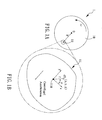
- FIG. 1A and FIG. 1B are schematic diagrams of a swinging apparatus according to one embodiment of the present invention.
- the swinging apparatus 1 comprises a swinging mechanism 11, which is coupled to an energy provider 10.
- the energy provider 10 is capable of rotating with an angular velocity of ⁇ .
- the swinging mechanism 11 resonates with the movement of the energy provider 10.
- the ratio of the specific distance R to the characteristic value L * is in a range between 4 and 0.25, In other words, the root value of the ratio is in a range between 2 and 0.5, expressed as Equation (8): 2 ⁇ R L * ⁇ 0.5
- the energy storage device 43 is coupled to the induction coil 421.
- the energy storage device 43 is implemented by a battery or other energy storage devices.
- the energy storage device 43 is further coupled to a sensor 44, which can be implemented by a pressure sensor, a temperature sensor or other sensors.
- the magnetic swinging mechanism 41 resonates to swing in the pipe.
- an induced current is induced in the induction coil 421 on the outer wall of the pipe 420 to further store the induced electrical energy in the energy storage device 43 to be supplied to the sensor 44.
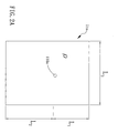
- the connecting portion 410 is analogous to the object 113 in FIG. 2C
- the pair of magnetic objects 412 and 413 are analogous to the object 114.
- the energy harvester 5 as formed in FIG 2A is used.
- the energy harvester comprises an energy provider 50, a magnetic swinging mechanism 52, an induction coil 53 and an energy storage device 54.
- the energy provider 50 is as previously stated and is not repeated herein.
- the magnetic swinging mechanism 52 swings with respect to a fulcrum 51.
- the magnetic swinging mechanism 52 comprises an object 520, which is coupled to magnetic objects 521 on both sides.
- the object 520 and the magnetic objects 521 can be formed as a single object with magnetism.
- the induction coil 53 and the energy storage device 54 are as previously stated and are not repeated herein.
- the energy storage device 54 can be coupled to the sensor, which is as previously stated and is not repeated herein.
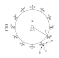
- the rim is rotating or rolling to change the gravity experienced by the swinging portion so that the swinging portion 210 in the swinging mechanism 21 swings.
- the swinging portion 210 disposed on the energy provider 20 swings with respect to a fulcrum 2100.
- the fulcrum 2100 is coupled to the energy provider 20 via a shaft 90.
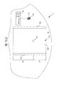
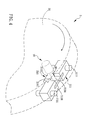
- FIG 5A and FIG 5B are schematic diagrams showing the operations of a swinging apparatus according to another embodiment of the present invention.
- a swinging apparatus 2 is shown comprising a swinging mechanism 21 disposed on the energy provider 20a.
- the energy provider 20a is a rim.
- Label 22 denotes the tire attached onto the rim 20a.
- the swinging portion and the weight loading portion in FIG. 5B are reduced from the swinging portion and the weight loading portion in FIG 4 , wherein identical labels denote identical elements.
- Equation (17) and Equation (18) as m 1 , m 2 , L 1 and L 2 are properly selected, ⁇ n ⁇ ⁇ .
- the swinging mechanism 21 is resonating with the rotational frequency when the swinging mechanism 21 is rotating with the wheel. Therefore, the maximum amplitude of the rotational frequency of the swinging mechanism 21 is achieved due to resonance so as to harvest the work accomplished on the swinging mechanism experiencing the gravity when the wheel is rolling.
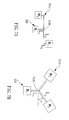
- the swinging portion 210 is similar to the swinging portion in FIG 4 except that the weight loading portion 210 in FIG. 7A to FIG. 7D is modified based on the spirits as previously stated.
- the weight loading portion 211 a comprises a plurality of shafts, namely the shaft L 2 and the shaft L 3 . Taking the shaft on the right side of the fulcrum 2100 for example, the shaft L 2 is coupled to the fulcrum 2100 on one end and is coupled to the shaft L 3 on the other end.
- the weight loading portion 211b in the present embodiment comprises a pair of shafts coupled to the fulcrum 2100 on one end, and an angle ⁇ is between the two shafts and the horizontal line.
- the weight loading portion 211d is similar to the weight loading portion 211c in FIG. 4 except that the fulcrum 2100 coupled to the shafts is not located at the center. Therefore, the distances from the objects m 2 and m 3 to the fulcrum are L 2 and L 3 , respectively.
- the swinging portion 210a and the weight loading portion 211e are structured as a cross shape.
- the swinging portion 210a comprises a shaft L 1 .
- the shaft L 1 is coupled to an object m 1 on one end, and is coupled to a fulcrum 2100 on the other end.
- the weight loading portion 211e comprises a shaft L 2 and two shafts L 3 . These three shafts L 2 and L 3 are connected to the fulcrum 2100 on one end, and connected to objects m 2 and m 3 , respectively, on the other end.
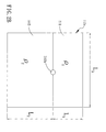
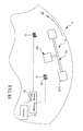
- the energy harvester 3 comprises an energy provider 30, a magnetic swinging mechanism 31 and a pair of induction coils 33.
- the energy provider 30 is structured as the energy provider 20 in the previous embodiment in FIG. 4 , and thus a description is not repeated herein.
- the magnetic swinging mechanism 31 comprises a swinging portion 310 and a weight loading portion 311.
- the swinging portion 310 and the weight loading portion 311 are structured as those in FIG. 4 except that the objects 3110 on both ends of the weight loading portion 311 are magnetic objects, which may provide a magnetic field.
- the pair of induction coils 33 is disposed respectively on one side of the magnetic objects 3110.
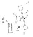
- FIG. 8B is a schematic diagram of an energy harvester according to still another embodiment of the present invention.
- the present embodiment is similar to the embodiment in FIG. 8A except that the object 3100 of the swinging portion 310 in the present embodiment is a magnetic object. Therefore, the induction coil 33 is disposed on a position corresponding to the magnetic object 3100 of the swinging portion 310.
- the energy storage device 34 is further coupled to a sensor 35.
- the sensor 35 is a pressure sensor for detecting whether the tire pressure is normal.
- the magnetic swinging mechanism 31 can be replaced according to FIG 7A to FIG. 7F .
Landscapes
- Engineering & Computer Science (AREA)
- Power Engineering (AREA)
- Other Liquid Machine Or Engine Such As Wave Power Use (AREA)
- Vibration Prevention Devices (AREA)
- Harvesting Machines For Root Crops (AREA)
- Connection Of Motors, Electrical Generators, Mechanical Devices, And The Like (AREA)
Applications Claiming Priority (1)
| Application Number | Priority Date | Filing Date | Title |
|---|---|---|---|
| TW097138635A TWI438337B (zh) | 2008-10-08 | 2008-10-08 | 擺動裝置及其獵能裝置 |
Publications (2)
| Publication Number | Publication Date |
|---|---|
| EP2175547A2 true EP2175547A2 (fr) | 2010-04-14 |
| EP2175547A3 EP2175547A3 (fr) | 2010-09-29 |
Family
ID=40940607
Family Applications (1)
| Application Number | Title | Priority Date | Filing Date |
|---|---|---|---|
| EP09158392A Withdrawn EP2175547A3 (fr) | 2008-10-08 | 2009-04-21 | Appareil oscillant et collecteur d'énergie l'utilisant |
Country Status (3)
| Country | Link |
|---|---|
| US (1) | US8166810B2 (fr) |
| EP (1) | EP2175547A3 (fr) |
| TW (1) | TWI438337B (fr) |
Cited By (5)
| Publication number | Priority date | Publication date | Assignee | Title |
|---|---|---|---|---|
| DE102010037626A1 (de) | 2010-09-17 | 2012-03-22 | Arne Hammer | Vorrichtung zur Erzeugung elektrischer Energie aus ungleichmäßiger Bewegung |
| WO2012067707A1 (fr) * | 2010-11-17 | 2012-05-24 | Massachusetts Institute Of Technology | Collecteur d'énergie passif, auto-accordé, servant à extraire de l'énergie d'un mouvement de rotation |
| EP3751163A1 (fr) | 2019-06-14 | 2020-12-16 | Off-Highway Powertrain Services Germany GmbH | Arbre articulé |
| GB2608656A (en) * | 2021-07-09 | 2023-01-11 | Univ Loughborough | Vibration Energy Harvesting Device |
| US11578762B2 (en) | 2019-02-15 | 2023-02-14 | Off-Highway Powertrain Services Germany GmbH | Journal cross and universal joint comprising the same |
Families Citing this family (7)
| Publication number | Priority date | Publication date | Assignee | Title |
|---|---|---|---|---|
| WO2008012850A1 (fr) * | 2006-07-28 | 2008-01-31 | Pirelli Tyre S.P.A. | Roue pour véhicules |
| DK2268494T3 (da) * | 2008-03-10 | 2012-05-14 | Ceramtec Gmbh | Indretning til at generere energi i et roterende system |
| US8297392B2 (en) * | 2009-09-25 | 2012-10-30 | Caterpillar Inc. | Hybrid energy management system |
| US9121394B2 (en) | 2013-04-04 | 2015-09-01 | Metso Minerals Industries, Inc. | Energy harvester for converting vibrational motion of a vibrating equipment into electrical energy, and a device for monitoring the operation of a vibrating equipment |
| TR201810314T4 (tr) | 2015-11-04 | 2018-08-27 | Univ Yeditepe | Bir enerji üretim sistemi. |
| US10243136B2 (en) | 2016-08-22 | 2019-03-26 | Masoud Ghanbari | Piezoelectric energy harvesting system from vehicle's tires |
| CN110319169A (zh) | 2019-06-15 | 2019-10-11 | 吴钦发 | 一种单向动力转换装置及具有该装置的动力系统 |
Citations (6)
| Publication number | Priority date | Publication date | Assignee | Title |
|---|---|---|---|---|
| US6407484B1 (en) | 2000-09-29 | 2002-06-18 | Rockwell Technologies Inc | Piezoelectric energy harvester and method |
| US20040075363A1 (en) | 2002-10-21 | 2004-04-22 | Malkin Matthew C. | Multi-frequency piezoelectric energy harvester |
| US20050151375A1 (en) | 2004-01-12 | 2005-07-14 | Rockwell Scientific Licensing, Llc. | Autonomous power source |
| US7116036B2 (en) | 2004-08-02 | 2006-10-03 | General Electric Company | Energy harvesting system, apparatus and method |
| US20070152511A1 (en) * | 2005-12-28 | 2007-07-05 | Usc Corporation | Generating device |
| US7256505B2 (en) | 2003-03-05 | 2007-08-14 | Microstrain, Inc. | Shaft mounted energy harvesting for wireless sensor operation and data transmission |
Family Cites Families (8)
| Publication number | Priority date | Publication date | Assignee | Title |
|---|---|---|---|---|
| US5409049A (en) * | 1992-05-29 | 1995-04-25 | Cycloid Company | Tangential tire pressurizing and regulating apparatus |
| US5707215A (en) * | 1994-11-14 | 1998-01-13 | Hughes Aircraft Company | Tuned resonant oscillating mass inflation pump and method of extracting electrical energy therefrom |
| US6411016B1 (en) * | 1999-11-12 | 2002-06-25 | Usc Co., Limited | Piezoelectric generating apparatus |
| AU2001268523A1 (en) | 2000-06-16 | 2001-12-24 | Martek Biosciences Corporation | High fluorescent intensity cross-linked allophycocyanin |
| US6742386B1 (en) * | 2000-10-30 | 2004-06-01 | International Truck Intellectual Property Company, Llc | Wheel mounted power generator and wheel condition sensing apparatus |
| JP2003209980A (ja) * | 2001-11-12 | 2003-07-25 | Jigyo Sozo Kenkyusho:Kk | 振動型発電装置 |
| US7126233B2 (en) * | 2003-09-15 | 2006-10-24 | Set Industries Corporation | Methods and apparatuses for generating electrical power in a rotating reference frame |
| US7629700B2 (en) * | 2006-10-05 | 2009-12-08 | Marshall University Research Corp. | Motion induced electrical generator for charging and operating devices |
-
2008
- 2008-10-08 TW TW097138635A patent/TWI438337B/zh not_active IP Right Cessation
-
2009
- 2009-04-08 US US12/420,166 patent/US8166810B2/en not_active Expired - Fee Related
- 2009-04-21 EP EP09158392A patent/EP2175547A3/fr not_active Withdrawn
Patent Citations (6)
| Publication number | Priority date | Publication date | Assignee | Title |
|---|---|---|---|---|
| US6407484B1 (en) | 2000-09-29 | 2002-06-18 | Rockwell Technologies Inc | Piezoelectric energy harvester and method |
| US20040075363A1 (en) | 2002-10-21 | 2004-04-22 | Malkin Matthew C. | Multi-frequency piezoelectric energy harvester |
| US7256505B2 (en) | 2003-03-05 | 2007-08-14 | Microstrain, Inc. | Shaft mounted energy harvesting for wireless sensor operation and data transmission |
| US20050151375A1 (en) | 2004-01-12 | 2005-07-14 | Rockwell Scientific Licensing, Llc. | Autonomous power source |
| US7116036B2 (en) | 2004-08-02 | 2006-10-03 | General Electric Company | Energy harvesting system, apparatus and method |
| US20070152511A1 (en) * | 2005-12-28 | 2007-07-05 | Usc Corporation | Generating device |
Cited By (9)
| Publication number | Priority date | Publication date | Assignee | Title |
|---|---|---|---|---|
| DE102010037626A1 (de) | 2010-09-17 | 2012-03-22 | Arne Hammer | Vorrichtung zur Erzeugung elektrischer Energie aus ungleichmäßiger Bewegung |
| WO2012035126A2 (fr) | 2010-09-17 | 2012-03-22 | Arne Hammer | Dispositif pour générer de l'énergie électrique à partir d'un mouvement non uniforme |
| WO2012035126A3 (fr) * | 2010-09-17 | 2013-04-04 | Arne Hammer | Dispositif pour générer de l'énergie électrique à partir d'un mouvement non uniforme |
| WO2012067707A1 (fr) * | 2010-11-17 | 2012-05-24 | Massachusetts Institute Of Technology | Collecteur d'énergie passif, auto-accordé, servant à extraire de l'énergie d'un mouvement de rotation |
| US11578762B2 (en) | 2019-02-15 | 2023-02-14 | Off-Highway Powertrain Services Germany GmbH | Journal cross and universal joint comprising the same |
| EP3751163A1 (fr) | 2019-06-14 | 2020-12-16 | Off-Highway Powertrain Services Germany GmbH | Arbre articulé |
| US11632014B2 (en) | 2019-06-14 | 2023-04-18 | Off-Highway Powertrain Services Germany GmbH | Joint shaft |
| GB2608656A (en) * | 2021-07-09 | 2023-01-11 | Univ Loughborough | Vibration Energy Harvesting Device |
| WO2023281261A1 (fr) * | 2021-07-09 | 2023-01-12 | Loughborough University | Dispositif de collecte d'énergie de vibration |
Also Published As
| Publication number | Publication date |
|---|---|
| US20100083746A1 (en) | 2010-04-08 |
| EP2175547A3 (fr) | 2010-09-29 |
| TW201014973A (en) | 2010-04-16 |
| US8166810B2 (en) | 2012-05-01 |
| TWI438337B (zh) | 2014-05-21 |
Similar Documents
| Publication | Publication Date | Title |
|---|---|---|
| EP2175547A2 (fr) | Appareil oscillant et collecteur d'énergie l'utilisant | |
| US7679210B2 (en) | Vehicle wheel electricity generating device | |
| US5934882A (en) | Electrical generator system having a tuned resonant oscillating mass | |
| CN101754873B (zh) | 用于在车轮轮胎内产生电能的方法和系统 | |
| US7415874B2 (en) | Method and system for generating electrical energy within a vehicle tyre | |
| Pohl et al. | Monitoring the tire pressure at cars using passive SAW sensors | |
| JP2008526596A (ja) | タイヤモジュール及びタイヤモジュールを有する空気タイヤ | |
| CN102666146A (zh) | 用于在轮胎中产生电能的方法 | |
| CN103259453A (zh) | 用于风力发电机叶片监测系统的压电悬臂梁发电机 | |
| CN203313094U (zh) | 用于风力发电机叶片监测系统的压电悬臂梁发电机 | |
| US11203235B2 (en) | System for tires pressure and wear detection | |
| CN111038184B (zh) | 旋转轮和能量收集系统 | |
| CN101725492B (zh) | 摆动装置及其猎能装置 | |
| US7830072B2 (en) | Electromechanical rotation converter and a method for generating electrical energy using an electromechanical rotation converter | |
| CN103493357B (zh) | 能量采集器及其矩阵、矩阵系统和模块、轮胎和鞋类 | |
| EP2614582B1 (fr) | Structure collectrice de puissance et procédé | |
| Wang et al. | Wideband electromagnetic energy harvesting from a rotating wheel | |
| KR101295797B1 (ko) | 회전체를 이용한 전력 발생장치 | |
| CN203313093U (zh) | 一种基于夹持限位的轮式压电梁发电机 | |
| JP4198818B2 (ja) | タイヤ回転数測定装置 | |
| CN203326919U (zh) | 一种悬锤自激轮式发电机 | |
| JP5405795B2 (ja) | 発電装置及びタイヤ空気圧測定装置 | |
| CN102055300A (zh) | 摆动装置及其转动状态检测装置与信息显示装置 | |
| Wang et al. | Based on tire pressure monitor system analysis to design energy harvester |
Legal Events
| Date | Code | Title | Description |
|---|---|---|---|
| PUAI | Public reference made under article 153(3) epc to a published international application that has entered the european phase |
Free format text: ORIGINAL CODE: 0009012 |
|
| AK | Designated contracting states |
Kind code of ref document: A2 Designated state(s): AT BE BG CH CY CZ DE DK EE ES FI FR GB GR HR HU IE IS IT LI LT LU LV MC MK MT NL NO PL PT RO SE SI SK TR |
|
| AX | Request for extension of the european patent |
Extension state: AL BA RS |
|
| PUAL | Search report despatched |
Free format text: ORIGINAL CODE: 0009013 |
|
| AK | Designated contracting states |
Kind code of ref document: A3 Designated state(s): AT BE BG CH CY CZ DE DK EE ES FI FR GB GR HR HU IE IS IT LI LT LU LV MC MK MT NL NO PL PT RO SE SI SK TR |
|
| AX | Request for extension of the european patent |
Extension state: AL BA RS |
|
| 17P | Request for examination filed |
Effective date: 20110329 |
|
| 17Q | First examination report despatched |
Effective date: 20130225 |
|
| STAA | Information on the status of an ep patent application or granted ep patent |
Free format text: STATUS: THE APPLICATION IS DEEMED TO BE WITHDRAWN |
|
| 18D | Application deemed to be withdrawn |
Effective date: 20130910 |