EP2175306B1 - Multifokales Brillenglas - Google Patents
Multifokales Brillenglas Download PDFInfo
- Publication number
- EP2175306B1 EP2175306B1 EP09171373A EP09171373A EP2175306B1 EP 2175306 B1 EP2175306 B1 EP 2175306B1 EP 09171373 A EP09171373 A EP 09171373A EP 09171373 A EP09171373 A EP 09171373A EP 2175306 B1 EP2175306 B1 EP 2175306B1
- Authority
- EP
- European Patent Office
- Prior art keywords
- regions
- vision
- series
- wearer
- eyeglass
- Prior art date
- Legal status (The legal status is an assumption and is not a legal conclusion. Google has not performed a legal analysis and makes no representation as to the accuracy of the status listed.)
- Active
Links
- 230000004438 eyesight Effects 0.000 claims abstract description 160
- 238000012937 correction Methods 0.000 claims abstract description 75
- 238000000034 method Methods 0.000 claims abstract description 20
- 230000004886 head movement Effects 0.000 claims description 12
- 230000002093 peripheral effect Effects 0.000 claims description 10
- 230000000694 effects Effects 0.000 claims description 7
- 230000003247 decreasing effect Effects 0.000 claims description 3
- 238000004519 manufacturing process Methods 0.000 claims description 3
- 230000007423 decrease Effects 0.000 claims description 2
- 238000003754 machining Methods 0.000 claims description 2
- 208000029091 Refraction disease Diseases 0.000 abstract description 10
- 230000004430 ametropia Effects 0.000 abstract description 10
- 208000014733 refractive error Diseases 0.000 abstract description 10
- 239000011521 glass Substances 0.000 description 96
- 230000003287 optical effect Effects 0.000 description 27
- 210000003128 head Anatomy 0.000 description 25
- 241001639412 Verres Species 0.000 description 18
- 230000006870 function Effects 0.000 description 12
- 208000001491 myopia Diseases 0.000 description 11
- 238000012360 testing method Methods 0.000 description 10
- 238000010586 diagram Methods 0.000 description 7
- 210000000887 face Anatomy 0.000 description 5
- 210000001525 retina Anatomy 0.000 description 5
- 230000006872 improvement Effects 0.000 description 4
- 210000001747 pupil Anatomy 0.000 description 4
- 125000004122 cyclic group Chemical group 0.000 description 3
- 238000005192 partition Methods 0.000 description 3
- 230000000750 progressive effect Effects 0.000 description 3
- 230000000295 complement effect Effects 0.000 description 2
- 230000004424 eye movement Effects 0.000 description 2
- 239000000463 material Substances 0.000 description 2
- 230000016776 visual perception Effects 0.000 description 2
- 206010052804 Drug tolerance Diseases 0.000 description 1
- 206010020675 Hypermetropia Diseases 0.000 description 1
- 238000013459 approach Methods 0.000 description 1
- 239000000969 carrier Substances 0.000 description 1
- 230000008859 change Effects 0.000 description 1
- 239000003086 colorant Substances 0.000 description 1
- 230000007547 defect Effects 0.000 description 1
- 230000026781 habituation Effects 0.000 description 1
- 230000004305 hyperopia Effects 0.000 description 1
- 201000006318 hyperopia Diseases 0.000 description 1
- 210000003127 knee Anatomy 0.000 description 1
- 238000005259 measurement Methods 0.000 description 1
- 230000004379 myopia Effects 0.000 description 1
- 230000001144 postural effect Effects 0.000 description 1
- 201000010041 presbyopia Diseases 0.000 description 1
- 230000008569 process Effects 0.000 description 1
- 230000002269 spontaneous effect Effects 0.000 description 1
- 238000009966 trimming Methods 0.000 description 1
Images


Classifications
-
- G—PHYSICS
- G02—OPTICS
- G02C—SPECTACLES; SUNGLASSES OR GOGGLES INSOFAR AS THEY HAVE THE SAME FEATURES AS SPECTACLES; CONTACT LENSES
- G02C7/00—Optical parts
- G02C7/02—Lenses; Lens systems ; Methods of designing lenses
- G02C7/06—Lenses; Lens systems ; Methods of designing lenses bifocal; multifocal ; progressive
-
- G—PHYSICS
- G02—OPTICS
- G02C—SPECTACLES; SUNGLASSES OR GOGGLES INSOFAR AS THEY HAVE THE SAME FEATURES AS SPECTACLES; CONTACT LENSES
- G02C7/00—Optical parts
- G02C7/02—Lenses; Lens systems ; Methods of designing lenses
- G02C7/024—Methods of designing ophthalmic lenses
-
- G—PHYSICS
- G02—OPTICS
- G02C—SPECTACLES; SUNGLASSES OR GOGGLES INSOFAR AS THEY HAVE THE SAME FEATURES AS SPECTACLES; CONTACT LENSES
- G02C7/00—Optical parts
- G02C7/02—Lenses; Lens systems ; Methods of designing lenses
- G02C7/024—Methods of designing ophthalmic lenses
- G02C7/027—Methods of designing ophthalmic lenses considering wearer's parameters
-
- G—PHYSICS
- G02—OPTICS
- G02C—SPECTACLES; SUNGLASSES OR GOGGLES INSOFAR AS THEY HAVE THE SAME FEATURES AS SPECTACLES; CONTACT LENSES
- G02C7/00—Optical parts
- G02C7/02—Lenses; Lens systems ; Methods of designing lenses
- G02C7/06—Lenses; Lens systems ; Methods of designing lenses bifocal; multifocal ; progressive
- G02C7/061—Spectacle lenses with progressively varying focal power
Definitions
- the present invention relates to a method for producing a multifocal lens of ophthalmic spectacles.
- a lens of ophthalmic spectacles intended for a presbyopic wearer must produce ophthalmic corrections appropriate for several viewing distances.
- multifocal or progressive lenses have been provided for a long time, which have different optical powers between different parts of these glasses.
- Such a lens provides the wearer an ophthalmic correction which is adapted to the distance of an object viewed, if the direction of the gaze of the wearer passes through the glass in a portion thereof that has been provided for this viewing distance.
- a wearer who is newly equipped with such a glass must then get used to orient his head and his eyes according to the distance of distance from the object being looked at, to use the appropriate part of the glass.
- the multifocal or progressive lenses that are currently available are adapted to allow the wearer to read looking down. They are therefore suitable for reading a book that is placed on a table or held on the knees in a sitting position.
- the ophthalmic correction that is produced in the lower part of these glasses is adapted for near vision, that is to say for a viewing distance of about 0.4 m (meter). It is therefore unsuitable for looking at obstacles that are located on the ground in front of the wearer, at a distance from the wearer's eyes that is greater than 0.5 m. Now, such a situation is the approach of a staircase, for example.
- the image of the first steps of the staircase which is formed on the retina of the wearer is not clear, and the wearer may be the victim of an accident caused by this poor visual perception.
- Another example of a situation where current multifocal or progressive lenses are not suitable is reading a writing page that is hanging on a wall at eye level. Indeed, the wearer is then led to read the document through the far vision zone of his glasses of glasses.
- the document EP 0 367 878 describes a concentric-zone lens that has several focal length values at any point on its surface.
- Such a lens can simultaneously provide two ophthalmic correction values, for example for distance vision and for near vision, whatever the direction of gaze through the lens.
- part of the optical power is provided by light diffraction effect, such a glass has a significant chromaticism.
- the effective optical power of the glass can not then be tuned precisely for all colors in relation to the sphere defect that is determined for an ametropic subject.
- part of the light that enters through the pupil converges according to a distance focal that is not appropriate. This portion of light then does not participate in the sharp image that is produced on the retina of the wearer in accordance with that of the focal lengths that is appropriate. This results in a loss of contrast that affects the wearer's vision in all circumstances.
- An object of the present invention is therefore to provide an ophthalmic lens to presbyopic carrier, according to a new method to avoid the disadvantages of previous glasses.
- a spectacle lens made according to the invention produces, in its main vision zone, an ophthalmic correction which is adapted to the wearer for the first viewing distance. All or most of the light that passes through the pupil's pupil and forms an image on his retina then passes through the main viewing area of the lens, so that the image of the object being viewed has maximum contrast.
- the vision of the wearer is therefore corrected optimally for the first viewing distance when the direction of his gaze passes through the main viewing area, especially near a center thereof.
- the quality of ophthalmic correction that provides the multifocal glass of the invention is similar to that of a unifocal lens.
- the glass produced according to the invention also has a secondary vision zone, of which separate parts are dedicated to the ophthalmic correction of the wearer for several second viewing distances.
- a secondary vision zone of which separate parts are dedicated to the ophthalmic correction of the wearer for several second viewing distances.
- Such an allocation of regions within the secondary vision zone, separately and respectively to ophthalmic corrections established for several viewing distances that are different, does not result from a diffractive effect. In this way, the glass does not exhibit significant chromaticism.
- glass parameters that are determined and then applied in regions of two different series may comprise a mean curvature of a glass surface and / or a refractive index of a glass material.
- the corrections which are respectively adapted to the different viewing distances, are available simultaneously in the secondary vision zone.
- the step of alternating regions with respect to the ophthalmic corrections that are produced is then less than the diameter of the pupil of the wearer.
- the same lower part of the lens when it is located in the secondary vision zone provided according to the invention, can provide the wearer with a near vision that is clear, particularly for a reading activity, and a vision of obstacles on the ground in front of the wearer that is also clean.
- the wearer has a visual perception that is clear in every circumstance.
- the main vision zone and the regions of each series are determined by variations of at least one parameter of the same first surface of the ophthalmic lens.
- a second surface of the glass can then be modified in order to adapt the lens to the ophthalmic correction of the wearer, at least for the first viewing distance.
- identical semi-finished glasses that determine the main viewing area and the different sets of regions within the secondary viewing area can be used for carriers with ophthalmic corrections that are different for the first distance. of vision.
- Parametric variations between regions belonging to different series can form discontinuities of the first surface itself.
- a gain in thickness and lightening of the glass can result.
- This first surface may be the convex front surface of the glass, or its concave posterior surface. It can also be an intermediate surface between the anterior and posterior faces of the glass, which separates two media transparencies having different values of a refractive index of light.
- the main viewing area may contain a disk of radius 1 mm. It is then traversed by a significant proportion of the light rays that form an image on the retina of the wearer, when the direction of gaze of it passes through or near a center of the main viewing area. The contrast of the image on the retina of the wearer is then more particularly high.
- a size and / or a position of the main vision zone in the lens can be adapted according to the wearer, in particular according to the postural habits of the latter.
- the glass can provide superior comfort, or reduce a possible initial duration of habituation of the wearer.
- the size and / or position of the main viewing area can be determined in step / 2 / as a function of a main activity of the wearer, which implements the first viewing distance.
- the secondary viewing zone of the glass which provides clear vision for several different viewing distances, may be closer to a central point in the main viewing area that is widely used by a wearer who primarily rotates the viewer. head by changing direction of gaze.
- the main viewing area may be larger for a wearer who turns his eyes rather than the head.
- a proportion of the regions of at least one series inside the secondary vision zone of the glass can be determined according to an activity of the wearer using the second viewing distance. which is assigned to this series.
- this proportion of the regions of the selected series can alternatively be determined according to the amplitude of the head movement which is performed by the wearer, when he looks successively in different directions. It is determined so that a quotient of a sum of area surfaces of this series by a surface of a corresponding portion of the secondary vision area, increases as a function of the magnitude of head movement made by the wearer .
- a multifocal ophthalmic lens that is made according to the invention can be adapted to produce a correction of myopia or hyperopia correction of the distant vision of the wearer.
- the secondary vision zone can be divided into two series of regions, with the first viewing distance and any second viewing distance that can be equal.
- One of the second viewing distances may be greater than 2 m, corresponding to the distant vision of the wearer.
- the other second viewing distance may be between 0.3 m and 0.5 m, corresponding to a near vision, or be between 0.5 m and 2 m, corresponding to an intermediate vision distance.
- the spectacle lens that is made from the lens then produces a first optical power that is identical in the main viewing area and in the regions of one of the series. It simultaneously produces a second optical power in the regions of the other series, which is different from the first optical power.
- Such a lens thus provides a vision that is clear throughout the lens for a first viewing distance, and for a second viewing distance through the secondary viewing area.
- the secondary vision zone may be divided into three series of regions, with the first viewing distance and any second viewing distance that may be equal.
- One of the second viewing distances may be between 0.3 m and 0.5 m. It corresponds to the close vision of the wearer.
- another of the second viewing distances may be between 0.5 m and 2 m, corresponding to an intermediate vision distance, and a last of the second viewing distances may be greater than 2 m, corresponding to the distance vision .
- the spectacle lens then produces a first identical optical power in the main viewing area and in the regions of one of the series. It simultaneously produces two different optical powers, respectively in the other two series of regions. Such another lens thus provides a vision that is clear throughout the lens for a first viewing distance, and for two other viewing distances in the secondary vision area.
- an ophthalmic lens 1 comprises an anterior surface S1 and a posterior surface S2.
- the anterior faces S1 and posterior S2 are thus designated with respect to the position of use of the lens 1 by a carrier thereof.
- the lens 1 can form a semi-finished or finished glass.
- Semi-finished glass is understood to mean a blank of glasses, of which only one of the anterior or posterior faces has a definitive shape. The other face is then machined later, in particular to give the finished glass optical power values that correspond to the ametropia that has been determined for the future carrier of the glass.
- the lens 1 is a semi-finished glass, it has an initial peripheral edge 30 which can be circular with a diameter of 60 mm, for example.
- its peripheral edge may be that of semi-finished glass. This edge may also have been cut to the dimensions of an eyeglass frame housing, in which the glass is intended to be assembled.
- the contour 31 on the figure 1b represents the edge of such a finished spectacle lens after trimming.
- the lens 1 is divided into several zones parallel to one of the faces S1 or S2, including a main vision zone 10 and a secondary vision zone 20.
- the secondary vision zone 20 may surround the main vision zone 10 inside the peripheral edge 30 or 31, but it this is just a particular configuration for illustrative purposes, and the Figures 8b to 8d described later show other possible configurations.
- the secondary vision zone 20 may be limited to a reduced angular sector around or on one side of the main viewing zone 10.
- O designates a central point of the main viewing area 10. It will be assumed initially that the main viewing zone 10 is substantially centered in the glass, relative to the peripheral edge 30 or 31. In this case, the point O may be confused with the mounting cross of the glass, which is taken as a reference for placing the glass relative to a spectacle frame housing in which it is intended to be assembled.
- the main viewing area 10 may contain a disk of radius 1 mm.
- the main viewing area 10 can be contained in a 7.5 mm radius disc.
- the secondary vision zone 20 provides the wearer with second ophthalmic corrections that are adapted to several viewing distances, for eccentricity values from and above about 15 ° (degree).
- the secondary viewing zone 20 has a surface that is sufficient to implement the invention, even when the housing of the glass in the frame is small.
- the main viewing zone 10 is dedicated to a first ametropia correction of the wearer, established for a first distance of vision.
- the finished lens that is made from the lens 1 has a first optical power in the area 10. This first optical power is generally constant throughout the area 10.
- the secondary vision zone 20 can be divided into two series of contiguous regions, which are referenced 21 or 22 depending on whether they belong to a first or second of the two series, respectively.
- the regions 21 and 22 are alternated and respectively dedicated according to the series to obtain two ophthalmic corrections for the wearer of the finished glass.
- the regions 21 are dedicated to obtaining a second ametropia correction
- the regions 22 are dedicated to obtaining yet another ametropia correction, which is different from the second correction.
- the ophthalmic correction which is produced in the regions 21 of the first series on the one hand, and that which is produced in the regions 22 of the second series on the other hand, are established for the wearer for two distances of different vision from each other.
- a glass according to the invention is of the multifocal type, and is particularly suitable for a presbyopic wearer.
- the second ametropia correction that is produced by the glass in the regions 21 may be identical to the first correction that is produced in the main viewing area 10.
- Each ophthalmic correction, and in particular the first ophthalmic correction that is produced in the main vision zone 10, can be determined for the wearer in one of the ways known to those skilled in the art.
- the correction that is associated with one of the series of regions of the secondary vision zone 20 can be deduced from a combination between the first ophthalmic correction of the main vision zone 10 with another of the second corrections that is produced. in regions of a different series.
- all the ophthalmic corrections considered in the present invention concern the foveal vision of the wearer.
- a glass according to the invention is made in the main viewing area 10 according to a first set of parameters which corresponds to the first ametropia correction. Likewise, it is performed in the regions of each series within the secondary vision zone 20 according to a second set of parameters which corresponds to one of the second ametropia corrections. These second sets of parameters vary from one series to another, depending on the corresponding ophthalmic corrections. All these parameters may be curvatures of a face of the lens 1, for example the face S1, in the corresponding regions or zones. In this case, the face S1 has discontinuities of curvature between two regions 21 and 22 which are contiguous, and between the main vision zone 10 and those of the regions 21 or 22 which is contiguous thereto. Possibly, these discontinuities of curvature can be superimposed on discontinuities of sagittal height, perpendicular to the face S1 ( figure 1 a) .
- the optical power of the finished glass in the main viewing area 10 is denoted P 1 .
- the one produced in the regions of one of the series, for example the regions 22, is noted P 2 .
- the optical power P 2 can be constant or vary according to a radial distance measured on the glass from a reference point, for example the point O. Such constancy or variation occurs from one region 22 to another, and possibly within each region 22.
- the optical power P 2 can first grow from the boundary between the zones 10 and 20, in algebraic value and depending on the eccentricity, until reaching a maximum value and then decreasing towards the peripheral edge 30 or 31.
- eccentricity refers to an angle between the direction of gaze of the wearer through the glass and a reference direction which passes through a fixed point of the glass.
- This fixed point may be the mounting cross which is printed on the glass, and which generally corresponds to the direction of gaze ahead for the wearer.
- the eccentricity of the direction of gaze of the wearer through the glass can be identified by the radial distance on the glass between the mounting cross and the crossing point of the anterior face S1 of the glass by this viewing direction. It is noted E in the following. For simplicity of part of the description, it will be assumed in a first step that the center O of the main viewing zone 10 coincides with the glass mounting cross.
- the value of the optical power P 2 inside the regions 22 can be the same throughout the secondary vision zone 20.
- between the value of the optical power P 2 in the regions 22 on the one hand, and the value of the optical power P 1 in the main viewing zone 10 on the other hand can vary progressively as a function of the eccentricity E. Such a variation thus occurs from one region 22 to another of the same series moving in the direction of the peripheral edge 30 or 31, as well as within each region 22.
- the optical power P 2 can be constant inside each region 22, whereas the absolute difference
- any of the types of optical power variations that are enumerated for the regions 22 can be implemented simultaneously, in a similar and independent manner for each series of regions within the region.
- the optical power may vary in the regions 21 in a manner that is different from that in the regions 22.
- the regions of one of the series within the secondary vision zone 20 may each have at least one dimension which is between 15 ⁇ m (micrometer) and 1000 ⁇ m, preferably between 25 ⁇ m and 50 ⁇ m. .mu.m.
- the partition of the secondary vision zone 20 between the regions 21 and 22 does not cause any significant diffraction, while remaining invisible or almost invisible to the naked eye. No discomfort therefore results for the wearer, and the glass retains an aesthetic quality that is compatible with the requirements of the ophthalmic field.
- the alternating pitch of the regions in the secondary vision zone is the offset distance between two successive regions belonging to the same series.
- the alternating step of regions 21 and 22 ( Figures 1a and 1b ) is the offset distance between two regions 21 which are separated by a single region 22. It is noted s in the figures.
- the alternate step has local values in the secondary vision zone. It can be constant or vary within this zone, while remaining less than 1 mm.
- the regions 21, 22 of each series may be bands which are arranged in an angular sector around at least a part of the main viewing area 10 These bands of regions can then be alternated along radial directions which start from the center of the main viewing zone portion 10 towards the peripheral edge 30 or 31 of the lens.
- the width of each region band 22 may be between 15 ⁇ m and 1000 ⁇ m, preferably between 25 ⁇ m and 50 ⁇ m, along the radial directions from the center O.
- the lens of Figures 2a and 2b is referenced globally 1 '.
- the lenses 1 and 1 ' have respective main viewing areas 10 which have identical dimensions. They are circular and centered on the same point O coincides with the mounting cross, and have the same radius r 10 .
- the alternating pitch of the regions 21 and 22 is identical for the lenses 1 and 1 '.
- the lenses 1 and 1 ' are differentiated by the values of a duty ratio of the regions 21 and 22.
- cyclic ratio of the regions 22 is meant the quotient of the dimension of the regions 22 in the direction of alternation with the regions of the other series, by the local value of the alternation step s. This duty cycle can be constant or vary in the secondary vision zone 20.
- the size of the principal vision zone 10 on the one hand, and the proportion of the regions of a selected series, for example the regions 22, in the secondary vision zone 20 on the other hand can be adapted to the wearer of the glass according to his propensity to turn more eyes or head when looking successively objects that are in two different directions. It is understood that the size of the zone 10 and the proportion of the regions 22 can thus be adapted independently of one another. In particular, the size of the zone 10 only can be adapted in this way to the wearer, or the proportion of the regions 22 in the zone 20 only.
- the relative magnitudes of eye and head movements made by the wearer to whom the glass is intended are first characterized.
- a first target called reference target
- the reference target is noted R on the figure 3a
- reference 100 designates the wearer. It can be located at eye level for the wearer, in particular.
- the wearer is therefore placed in front of the reference target R, with the shoulders substantially located in a vertical plane which is perpendicular to the virtual line which connects his head to the reference target. He then has the head and the eyes that are oriented toward the reference target.
- the wearer 100 is asked to look at a second target, called the test target and noted T, which is shifted relative to the reference target R, without moving the shoulders. To do this, he partly turns the head and partly the eyes ( figure 3b ), so that the direction of its gaze changes from the reference target R to the test target T.
- the test target T is shifted horizontally relative to the reference target R, so as to characterize the movements horizontal head and eyes of the wearer.
- the angular distance between the test target T and that of reference R, relative to the carrier 100, is denoted ⁇ .
- ⁇ T denotes the angle of rotation of the head of the carrier 100, also called the angular deflection of the head, to go from the first observation situation of the reference target R to the second observation situation of the target of test T.
- ⁇ Y is the angle of the rotation of the eyes which is carried out simultaneously by the carrier 100.
- the angular distance ⁇ is therefore equal to the sum of the two angles ⁇ T and ⁇ Y.
- the eccentricity E of the wearer's gaze through the lens corresponds to the angle of angular deflection ⁇ Y.
- the quotient of the angular deviation of the head ⁇ T is then calculated by the angular distance ⁇ . This quotient is equal to unity for a wearer who has exclusively turned his head to move from the reference target R to the test target T, and to zero for a wearer who has only turned his eyes.
- a gain G is then calculated for this "eye / head" movement coordination test which has been carried out for the carrier 100.
- the gain G can be defined by a predetermined function of the quotient of the angular deflection of the head ⁇ T by the angular distance ⁇ .
- This "eye / head” movement coordination test can be carried out by the wearer in the shop of an optician's retailer where he orders his pair of glasses equipped with the glass according to the invention.
- Other "eye / head” movement coordination tests that are equivalent to that just described can be performed alternately, without the implementation of the invention being modified in principle.
- the diagram of the figure 4 is an example of variation of the size of the main viewing area 10 as a function of the gain G.
- the area 10 still has a disk shape.
- the radius of this disc is noted r 10 and is plotted on the ordinate.
- the possible values of gain G are indicated on the abscissa.
- the variation of the radius r 10 can be linear, between a minimum value of 2 mm which is attributed when the gain G is equal to unity, and a maximum value of 7.5 mm which is attributed when the gain G is equal to zero.
- a size can be attributed to the main viewing area 10, which is further reduced as the wearer moves the head more when he looks successively in two different directions.
- the proportion of regions 22 in the secondary vision zone 20 may be a medium or local magnitude.
- Q average an average proportion, or overall proportion, it is denoted Q average and defined as the quotient of the sum of the areas of the regions of the selected series - the regions 22 - by a total area of the area of secondary vision 20.
- the bands of the regions of the selected series may have respective widths which are initially fixed throughout the secondary vision zone 20, according to the radial directions coming from the center O.
- the proportion of the regions 22 in zone 20 can be determined by selecting a value of the alternating step s.
- the bands of regions 22 can be more or less spaced or narrowed inside the zone 20.
- the value of the pitch s is then determined by the widths of the bands of regions which belong to the series other than that selected, to know the regions 21 in the example of Figures 1a and 1 b.
- the bands of the regions 22 may all have identical widths in the radial directions.
- the bands of the regions of the selected series - the regions 22 - can be distributed with an alternating pitch s which is initially fixed in the radial directions in the secondary vision zone 20.
- the proportion of the regions 22 in the zone 20 can then be determined by selecting a value of the cyclic ratio of the bands of the regions 22.
- the step of alternation s can be constant in the secondary vision zone 20.
- the lens of the Figures 1a and 1b on the one hand, and the lens 1 ' Figures 2a and 2b on the other hand, are distinguished from each other by such an adjustment of the proportion of regions 22 in the secondary vision zone 20.
- the proportion of the regions 22 within the secondary vision zone 20 may also be locally adjusted and vary between different points of the zone 20.
- a local value of the proportion is denoted Q local . It is determined from a portion of the area 20 which is reduced around a point considered, while containing portions of successive regions belonging to each series.
- the local local proportion Q can be determined in the same way as the average global proportion Q, considering local values for the alternation step s and for the cyclic ratio of the regions of the selected series with respect to the regions of the one or the other (s) series (s).
- the local local ratio Q of the regions 22 in the secondary viewing zone 20 is preferably an increasing function of the eccentricity E of the viewing direction through the lens.
- the regions of the selected series - the regions 22 - occupy an increasing proportion of the secondary vision zone 20, for radial distances on the glass from the center O of the zone 10 which are larger and larger.
- the diagram of the figure 5 represents such variations of the local local ratio Q of the regions 22 in the zone 20, for several possible values of the gain G.
- the values of the local proportion Q local are indicated on the ordinate, and the values of the eccentricity E of the look at through the glass are marked on the abscissa.
- the local proportion Q local is also an increasing function of the value of the gain G.
- the lens 1 'of Figures 2a and 2b then corresponds to a higher value of the gain G, relative to the lens 1 of the figures 1 a and 1 b.
- the overall average proportion Q may also be an increasing function of the gain value G.
- the semi-finished glass can be selected depending on the size of the main viewing area 10 and / or the proportion of the regions 22 in the area 20 determined for the wearer. Its final face may be the anterior face S1, in particular.
- Table 1 below groups together characteristics of four finished glasses for presbyopia which are in accordance with the invention ( ⁇ denotes the diopter unit): ⁇ u> Table 1 ⁇ / u> Glass 1 Glass 2 Glass 3 Glass 4 Radius r 10 of zone 10 10 mm 15 mm 5 mm 6.5 mm Number of series 2 3 2 2 Power P 1 in zone 10 - 4.00 ⁇ + 2.00 ⁇ - 6,00 ⁇ 0,00 ⁇ Power of Regions 21 - 4.00 ⁇ + 2.00 ⁇ - 6,00 ⁇ 0,00 ⁇ Power P 2 of regions 22 - 2.00 ⁇ 0,00 ⁇ > - 6,00 ⁇ + 2.00 ⁇ Power of Regions 23 + 1.00 ⁇ Maximum value of local Q 0.50 0.25 / 0.25 0.50 0.30 Variation of local Q with E constant constant constants constant increasing Difference
- the entire optical surface of the lens 1 produces an ophthalmic correction for the distant vision of the wearer.
- This correction for far vision is equal to -4.00 ⁇ , and the addition is + 2.00 ⁇ .
- the main viewing area 10 of the glass 1 may be located approximately in the center of the glass, and the secondary viewing zone 20 may be located at least partly below the main viewing zone 10 with respect to the position of use of the lens. glass.
- the secondary vision zone 20 of the lens 1 corrects both the distance vision and the near vision. It allows both the wearer to read a book that is placed on a table to see clearly the ground in front of him.
- the entire optical surface of the lens 2 corrects the near vision of the wearer, and the secondary vision zone 20 further corrects the intermediate vision and the far vision.
- the figure 8a shows alternation between the three series of regions in the secondary vision zone 20. These are noted respectively 21, 22 and 23.
- Table 1 indicates the respective constant values of the local proportion of the regions 22 and that of regions 23 in zone 20. They are both equal to 0.25, and are obtained by alternating bands of regions 21, 22 and 23 which have respective radial widths equal to 50 microns, 25 microns and 25 microns.
- the glass 2 can allow the wearer to clearly see a staircase in front of him and read a page of writing that is hung on a wall at eye level.
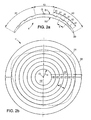
- the lens 3 is similar to the lens 1 with regard to the areas in which the near and far visions of the wearer are corrected, except that it corresponds to a first optical power P 1 that is different, and that the second optical power P 2 that is produced in regions 22 varies.
- the figure 6 shows these variations: the optical power P 2 increases progressively as a function of the eccentricity E, from the value - 5.7 ⁇ at the limit of the main viewing area 10 up to the maximum value of - 4.00 ⁇ .
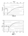
- the glass 4 is also similar to the glass 1 with regard to the zones in which the visions from far and near the wearer are corrected, but the proportion of the regions 22 which are dedicated to the correction of the near vision to the The interior of zone 20 increases with eccentricity E. figure 7 reproduces these variations: local Q gradually increases from the value 0.11 to the limit of the main vision zone 10, up to the maximum value 0.30.
- the figures 8b and 8c are respective plan views of two lenses according to the invention, which show possible configurations for the main viewing area 10 and the secondary viewing area 20.
- the main viewing area 10 includes a disc which is globally centered with respect to the peripheral edge 30, and an angular sector of pi radians around this disk, extending radially from it to the edge 30.
- the secondary vision zone 20 occupies the complementary angular sector.
- the angular sector of the zone 10 is situated in the top of the lens, with respect to the usual position of use of it.
- the secondary vision zone 20 is then located in the bottom of the lens.
- the zone 10 can be dedicated to the correction of the distance vision
- the zone 20 can contain two series of regions which can be dedicated respectively to the correction of the vision by far and that of the near vision .
- the glasses 1, 3 and 4 of Table 1 may have such a configuration.
- Zone 10 can be dedicated to near vision correction, and far and near vision can be corrected simultaneously in zone 20.
- the regions of each series within the secondary vision zone 20 may be semicircular bands which are alternated from the disk belonging to the region 10.
- figure 8d illustrates yet another lens configuration according to the invention, according to which the secondary vision zone 20 is a disc which is offset with respect to the mounting cross CM of the lens.
- the main viewing area 10 then occupies the remainder of the surface of the lens.
- the lenses 1, 3 and 4 of Table 1 can also have this configuration.
- the main viewing area, the secondary viewing area, and the series of regions may be defined by an intermediate surface of the lens.
- the lens may consist of two transparent elements which consist of respective materials having different values of a refractive index of light. These two elements of lens are contiguous according to the intermediate surface, with complementary shapes.
Landscapes
- Health & Medical Sciences (AREA)
- Ophthalmology & Optometry (AREA)
- Physics & Mathematics (AREA)
- General Health & Medical Sciences (AREA)
- General Physics & Mathematics (AREA)
- Optics & Photonics (AREA)
- Eyeglasses (AREA)
- Materials For Medical Uses (AREA)
- Medicines Containing Material From Animals Or Micro-Organisms (AREA)
Claims (14)
- Herstellungsverfahren für ein multifokales Glas (1) einer Brille für einen kurzsichtigen Träger, umfassend die folgenden Schritte:/1/ Erhalten einer ersten Sehkorrektur des Trägers für einen ersten Sehabstand und wenigstens zwei zweite Sehkorrekturen des Trägers für wenigstens zwei entsprechende zweite Sehabstände, wobei sich die zwei zweiten Korrekturen voneinander unterscheiden;/2/ Bestimmen eines Hauptsehbereichs (10) und eines Nebensehbereichs (20) des Glases;/3/ Aufteilen des Nebensehbereichs (20) in wenigstens zwei Bereichsserien (21, 22), wobei die Bereiche bezüglich der Serien mit einer Schrittgröße kleiner oder gleich 1 mm aneinandergrenzend und alterniert sind;/4/ Bestimmen der ersten Parameter des Glases im Hauptsehbereich (10) entsprechend der ersten Sehkorrektur, und für jede Bereichsserie (21, 22) Bestimmen der zweiten Parameter des Glases in den Bereichen der Serie abhängig von einer der zweiten, in Schritt /1/ erhaltenen und der jeweiligen Bereichsserie zugeordneten Sehkorrekturen; und/5/ Herstellen des Glases gemäß den ersten und zweiten Parametern, wobei das Verfahren dadurch gekennzeichnet ist, dass im Nebensehbereich (20) des Glases ein Verhältnis der Bereiche wenigstens einer aus den in Schritt /3/ verwendeten Bereichsserien ausgewählten Serie (22) gemäß einer Amplitude einer Kopfbewegung bestimmt wird, die der Träger (100) durchführt, wenn der Träger nacheinander in unterschiedlichen Richtungen angeordnete Gegenstände anschaut, sodass ein Quotient aus einer Summe der Flächen der Bereiche der gewählten Serie und einer Fläche eines entsprechenden Teils des Nebensehbereichs (20) in Abhängigkeit von der Amplitude der vom Träger durchgeführten Kopfbewegung zunimmt.
- Verfahren nach Anspruch 1, wobei der Hauptsehbereich (10) und die Bereiche jeder Serie (21, 22) durch Variationen wenigstens eines Parameters einer gleichen Fläche (S1, S2) des Glases bestimmt werden.
- Verfahren nach Anspruch 1 oder 2, wobei eine Größe und/oder eine Position des Hauptsehbereichs (10) in dem Glas in Schritt /2/ in Abhängigkeit von einer Aktivität des Trägers bestimmt werden, die den ersten Sehabstand betrifft.
- Verfahren nach Anspruch 1 oder 2, wobei der Schritt /2/ die folgenden Unterschritte umfasst:/2-1/ Beschreiben einer Amplitude einer Kopfbewegung des Trägers (100), die durchgeführt wird, wenn der Träger nacheinander in unterschiedlichen Richtungen angeordnete Gegenstände anschaut; und/2-2/ Bestimmen einer Größe des Hauptsehbereichs (10) des Glases, sodass die Größe des Hauptsehbereichs in Abhängigkeit von der für den Träger beschriebenen Amplitude der Kopfbewegung abnimmt.
- Verfahren nach einem der vorangehenden Ansprüche, wobei der Hauptsehbereich (10) des Glases, bei welchem die Parameter des Glases der ersten Sehkorrektur entsprechen, eine Scheibe mit einem Radius von 1 mm umfasst.
- Verfahren nach einem der vorangehenden Ansprüche, wobei die Bereiche jeder Serie (21, 22) Streifen sind, die in einem Winkelabschnitt rund um wenigstens einen Teil des Hauptsehbereichs (10) des Glases angeordnet werden und entlang radialer Richtungen von dem Teil des Hauptsehbereichs ausgehend zu einem Außenrand (30, 31) des Glases alterniert werden.
- Verfahren nach Anspruch 6, wobei die Streifen der Bereiche jeder gewählten Serie (22) jeweilige Größen aufweisen, die entsprechend den radialen Richtungen im Nebensehbereich (20) des Glases gewählt werden und wobei das Verhältnis der Bereiche der gewählten Serie in dem Nebensehbereich durch Auswählen wenigstens eines Wertes des Alternanzschrittes der Bereichsstreifen bezüglich der Serien bestimmt wird.
- Verfahren nach Anspruch 6, wobei die Bereichsstreifen (21, 22) bezüglich der Serien mit einem festgelegten Schrittwert entsprechend den Radialrichtungen im Nebensehbereich (20) des Glases alterniert werden und wobei das Verhältnis der Bereiche der gewählten Serie (22) im Nebensehbereich durch Auswählen wenigstens eines Wertes eines zyklischen Verhältnisses der Bereichsstreifen der gewählten Serie bestimmt wird.
- Verfahren nach einem der vorangehenden Ansprüche, wobei die Bereiche einer der Serien (21, 22) jeweils wenigstens eine Abmessung zwischen 15 µm und 1000 µm, vorzugsweise zwischen 25 µm und 50 µm aufweisen.
- Verfahren nach einem der Ansprüche 1 bis 9, wobei der Nebensehbereich (20) in zwei Bereichsserien (21, 22) aufgeteilt wird, und wobei der erste Sehabstand und ein beliebiger der zweiten Sehabstände gleich sind, wobei einer der zweiten Sehabstände größer als 2 m ist und der andere zweite Sehabstand zwischen 0,3 m und 0,5 m oder zwischen 0,5 m und 2 m liegt.
- Verfahren nach einem der Ansprüche 1 bis 9, wobei der Nebensehbereich (20) in drei Bereichsreihen (21, 22, 23) aufgeteilt wird und wobei der erste Sehabstand und ein beliebiger der zweiten Sehabstände gleich sind, wobei einer der zweiten Sehabstände zwischen 0,3 m und 0,5 m, ein anderer der zweiten Sehabstände zwischen 0,5 m und 2 m liegt und ein letzter der zweiten Sehabstände größer als 2 m ist.
- Verfahren nach einem der vorangehenden Ansprüche, wobei die Amplitude der von dem Träger (100) durchgeführten Kopfbewegung durch Ausführen der folgenden Schritte gekennzeichnet ist:- Messen eines Winkels einer Drehung des Kopfes des Trägers, wenn der Träger nacheinander zwei Objekte anschaut, die in winklig getrennten Richtungen angeordnet sind; und- Bestimmen eines Wertes eines Zuwachses, ausgehend von einem Quotienten aus einerseits dem für die Drehung des Kopfes gemessenen Winkel und andererseits einer Winkelentfernung zwischen den zwei Blickrichtungen, wobei der Zuwachs wie eine zunehmende Funktion oder eine abnehmende Funktion des Quotienten variiert.
- Verfahren nach einem der vorangehenden Ansprüche, wobei der Schritt /5/ die folgenden Unterschritte umfasst:/5-1/ Auswählen eines halbfertigen Glases (1), wobei von einer Vorderseite (S1) und einer Rückseite (S2) des Glases eine Seite einen Hauptsehbereich (10) und einen Nebensehbereich (20) definiert, wobei der Nebensehbereich in wenigstens zwei Bereichsserien (21, 22) aufgeteilt wird, welche bezüglich der Serien mit einer Schrittgröße kleiner oder gleich 1 mm aneinandergrenzend und alterniert sind, wobei das halbfertige Glas Abstände zwischen Sehkorrekturen festlegt, die jeweils für ein auf der Grundlage des halbfertigen Glases hergestelltes Fertigglas in dem Hauptsehbereich (10) und in jeder Bereichsserie (21, 22) erzeugt werden; und/5-2/ Fertigen der anderen Seite von Vorderseite (S1) und Rückseite (S2) des halbfertigen Glases, sodass das Glas die erste Sehkorrektur in dem Hauptsehbereich (10) erzeugt.
- Verfahren nach Anspruch 13, wobei das halbfertige Glas (1) im Unterschritt /5-1/ abhängig von der Größe des für den Träger (100) bestimmten Hauptsehbereichs (10) und/oder abhängig von dem für den Träger (100) bestimmten Verhältnis der Bereiche der gewählten Serie (22) im Nebensehbereich (20) gewählt wird.
Applications Claiming Priority (1)
| Application Number | Priority Date | Filing Date | Title |
|---|---|---|---|
| FR0856802A FR2936880B1 (fr) | 2008-10-07 | 2008-10-07 | Verre ophtalmique multifocal. |
Publications (2)
| Publication Number | Publication Date |
|---|---|
| EP2175306A1 EP2175306A1 (de) | 2010-04-14 |
| EP2175306B1 true EP2175306B1 (de) | 2012-03-14 |
Family
ID=40719165
Family Applications (1)
| Application Number | Title | Priority Date | Filing Date |
|---|---|---|---|
| EP09171373A Active EP2175306B1 (de) | 2008-10-07 | 2009-09-25 | Multifokales Brillenglas |
Country Status (4)
| Country | Link |
|---|---|
| US (1) | US8157376B2 (de) |
| EP (1) | EP2175306B1 (de) |
| AT (1) | ATE549656T1 (de) |
| FR (1) | FR2936880B1 (de) |
Cited By (1)
| Publication number | Priority date | Publication date | Assignee | Title |
|---|---|---|---|---|
| DE102014004381A1 (de) | 2014-03-26 | 2015-10-01 | Rodenstock Gmbh | Verbesserte ophthalmische Linse zur Presbyopie-Korrektion |
Families Citing this family (4)
| Publication number | Priority date | Publication date | Assignee | Title |
|---|---|---|---|---|
| FR2928745B1 (fr) * | 2008-03-14 | 2012-03-02 | Essilor Int | Realisation d'un nouveau verre de lunettes progressif. |
| JP6485888B1 (ja) * | 2017-10-24 | 2019-03-20 | 小松貿易株式会社 | 老眼鏡用レンズ及び老眼鏡 |
| US11126012B1 (en) | 2020-10-01 | 2021-09-21 | Michael Walach | Broadview natural addition lens |
| CN114415394A (zh) * | 2021-11-09 | 2022-04-29 | 阿尔玻科技有限公司 | 一种具有离焦功能的眼镜片及制备方法 |
Citations (1)
| Publication number | Priority date | Publication date | Assignee | Title |
|---|---|---|---|---|
| WO2009126946A1 (en) * | 2008-04-11 | 2009-10-15 | Pixeloptics Inc. | Electro-active diffractive lens and method for making the same |
Family Cites Families (10)
| Publication number | Priority date | Publication date | Assignee | Title |
|---|---|---|---|---|
| US1955047A (en) * | 1931-12-03 | 1934-04-17 | Howard D Beach | Spectacle lens |
| US5017000A (en) | 1986-05-14 | 1991-05-21 | Cohen Allen L | Multifocals using phase shifting |
| JPH01243017A (ja) * | 1988-03-24 | 1989-09-27 | Takahiro Okamoto | 眼鏡用レンズおよびこれを使用する眼鏡 |
| GB9005072D0 (en) | 1990-03-07 | 1990-05-02 | Bentley David Ltd | Improvements relating to calender and embossing bowls |
| AU7130391A (en) * | 1990-03-08 | 1991-09-12 | Breger, Joseph Laurence | Multifocal simultaneous vision lenses |
| US7281795B2 (en) * | 1999-01-12 | 2007-10-16 | Calhoun Vision, Inc. | Light adjustable multifocal lenses |
| US6712466B2 (en) * | 2001-10-25 | 2004-03-30 | Ophthonix, Inc. | Eyeglass manufacturing method using variable index layer |
| US20030117577A1 (en) * | 2001-12-20 | 2003-06-26 | Jones Larry G. | Multifocal ophthalmic lenses |
| AU2004325004B2 (en) * | 2004-11-16 | 2012-03-22 | Essilor International | Method for designing spectacle lenses taking into account an individual's head and eye movement |
| US7883207B2 (en) * | 2007-12-14 | 2011-02-08 | Pixeloptics, Inc. | Refractive-diffractive multifocal lens |
-
2008
- 2008-10-07 FR FR0856802A patent/FR2936880B1/fr not_active Expired - Fee Related
-
2009
- 2009-09-25 AT AT09171373T patent/ATE549656T1/de active
- 2009-09-25 EP EP09171373A patent/EP2175306B1/de active Active
- 2009-10-05 US US12/573,835 patent/US8157376B2/en active Active
Patent Citations (1)
| Publication number | Priority date | Publication date | Assignee | Title |
|---|---|---|---|---|
| WO2009126946A1 (en) * | 2008-04-11 | 2009-10-15 | Pixeloptics Inc. | Electro-active diffractive lens and method for making the same |
Cited By (2)
| Publication number | Priority date | Publication date | Assignee | Title |
|---|---|---|---|---|
| DE102014004381A1 (de) | 2014-03-26 | 2015-10-01 | Rodenstock Gmbh | Verbesserte ophthalmische Linse zur Presbyopie-Korrektion |
| DE102014004381B4 (de) | 2014-03-26 | 2023-08-10 | Rodenstock Gmbh | Verbesserte ophthalmische Linse zur Presbyopie-Korrektion sowie Verfahren zum Herstellen und Vorrichtung |
Also Published As
| Publication number | Publication date |
|---|---|
| ATE549656T1 (de) | 2012-03-15 |
| EP2175306A1 (de) | 2010-04-14 |
| FR2936880B1 (fr) | 2011-03-11 |
| US20100085535A1 (en) | 2010-04-08 |
| FR2936880A1 (fr) | 2010-04-09 |
| US8157376B2 (en) | 2012-04-17 |
Similar Documents
| Publication | Publication Date | Title |
|---|---|---|
| EP2175307B1 (de) | Augenglas zur Korrektur des fovealen und peripheren Sehens | |
| EP2440963B1 (de) | Herstellung eines nach unschärfewahrnehmung individuell angepassten gleitsichtbrillenglases | |
| EP2350735B1 (de) | Brillenglas mit brillensicht und zusätzlicher sicht | |
| EP0927377B2 (de) | Serie progressiver ophtalmischer multifokaler linsen | |
| FR2912820A1 (fr) | Realisation d'un element ophtalmique adapte pour les visions foveale et peripherique | |
| CA2708516C (fr) | Lentille ophtalmique progressive | |
| FR2916864A1 (fr) | Verre ophtalmique progressif de correction de myopie et procede de realisation d'un tel verre | |
| FR2924824A1 (fr) | Lentille progressive de lunettes ophtalmiques ayant une zone supplementaire de vision intermediaire | |
| WO2006072683A1 (fr) | Verre ophtalmique progressif et procede de fabrication d'un tel verre | |
| EP2175306B1 (de) | Multifokales Brillenglas | |
| FR2508186A1 (fr) | Lentille ophtalmique a pouvoir progressif | |
| WO2014060552A1 (fr) | Procede de determination d'une face d'un verre ophtalmique comportant une porteuse et une nappe fresnel et verre ophtalmique comprenant une telle face | |
| WO2009044080A2 (fr) | Réalisation d'un verre ophtalmique destiné à un porteur | |
| EP2252912A2 (de) | Reihe progressiver ophthalmischer linsen | |
| EP2713198A1 (de) | Progressive Augenlinse für Patient mit Sehschwäche | |
| FR2968095A1 (fr) | Element de verre ophtalmique progressif | |
| EP1171794A1 (de) | Nichtkorrigierende linse mit prismenkompensation und brille mit dieser linse |
Legal Events
| Date | Code | Title | Description |
|---|---|---|---|
| PUAI | Public reference made under article 153(3) epc to a published international application that has entered the european phase |
Free format text: ORIGINAL CODE: 0009012 |
|
| AK | Designated contracting states |
Kind code of ref document: A1 Designated state(s): AT BE BG CH CY CZ DE DK EE ES FI FR GB GR HR HU IE IS IT LI LT LU LV MC MK MT NL NO PL PT RO SE SI SK SM TR |
|
| AX | Request for extension of the european patent |
Extension state: AL BA RS |
|
| 17P | Request for examination filed |
Effective date: 20100823 |
|
| 17Q | First examination report despatched |
Effective date: 20100916 |
|
| GRAP | Despatch of communication of intention to grant a patent |
Free format text: ORIGINAL CODE: EPIDOSNIGR1 |
|
| RIC1 | Information provided on ipc code assigned before grant |
Ipc: G02C 7/06 20060101ALI20110819BHEP Ipc: G02C 7/02 20060101AFI20110819BHEP |
|
| RIN1 | Information on inventor provided before grant (corrected) |
Inventor name: DROBE, BJOERN |
|
| GRAS | Grant fee paid |
Free format text: ORIGINAL CODE: EPIDOSNIGR3 |
|
| GRAA | (expected) grant |
Free format text: ORIGINAL CODE: 0009210 |
|
| AK | Designated contracting states |
Kind code of ref document: B1 Designated state(s): AT BE BG CH CY CZ DE DK EE ES FI FR GB GR HR HU IE IS IT LI LT LU LV MC MK MT NL NO PL PT RO SE SI SK SM TR |
|
| REG | Reference to a national code |
Ref country code: GB Ref legal event code: FG4D Free format text: NOT ENGLISH |
|
| REG | Reference to a national code |
Ref country code: AT Ref legal event code: REF Ref document number: 549656 Country of ref document: AT Kind code of ref document: T Effective date: 20120315 Ref country code: CH Ref legal event code: EP |
|
| REG | Reference to a national code |
Ref country code: IE Ref legal event code: FG4D Free format text: LANGUAGE OF EP DOCUMENT: FRENCH |
|
| REG | Reference to a national code |
Ref country code: DE Ref legal event code: R096 Ref document number: 602009005864 Country of ref document: DE Effective date: 20120510 |
|
| REG | Reference to a national code |
Ref country code: NL Ref legal event code: VDEP Effective date: 20120314 |
|
| PG25 | Lapsed in a contracting state [announced via postgrant information from national office to epo] |
Ref country code: LT Free format text: LAPSE BECAUSE OF FAILURE TO SUBMIT A TRANSLATION OF THE DESCRIPTION OR TO PAY THE FEE WITHIN THE PRESCRIBED TIME-LIMIT Effective date: 20120314 Ref country code: NO Free format text: LAPSE BECAUSE OF FAILURE TO SUBMIT A TRANSLATION OF THE DESCRIPTION OR TO PAY THE FEE WITHIN THE PRESCRIBED TIME-LIMIT Effective date: 20120614 Ref country code: HR Free format text: LAPSE BECAUSE OF FAILURE TO SUBMIT A TRANSLATION OF THE DESCRIPTION OR TO PAY THE FEE WITHIN THE PRESCRIBED TIME-LIMIT Effective date: 20120314 |
|
| LTIE | Lt: invalidation of european patent or patent extension |
Effective date: 20120314 |
|
| PG25 | Lapsed in a contracting state [announced via postgrant information from national office to epo] |
Ref country code: LV Free format text: LAPSE BECAUSE OF FAILURE TO SUBMIT A TRANSLATION OF THE DESCRIPTION OR TO PAY THE FEE WITHIN THE PRESCRIBED TIME-LIMIT Effective date: 20120314 Ref country code: GR Free format text: LAPSE BECAUSE OF FAILURE TO SUBMIT A TRANSLATION OF THE DESCRIPTION OR TO PAY THE FEE WITHIN THE PRESCRIBED TIME-LIMIT Effective date: 20120615 Ref country code: FI Free format text: LAPSE BECAUSE OF FAILURE TO SUBMIT A TRANSLATION OF THE DESCRIPTION OR TO PAY THE FEE WITHIN THE PRESCRIBED TIME-LIMIT Effective date: 20120314 |
|
| REG | Reference to a national code |
Ref country code: AT Ref legal event code: MK05 Ref document number: 549656 Country of ref document: AT Kind code of ref document: T Effective date: 20120314 |
|
| PG25 | Lapsed in a contracting state [announced via postgrant information from national office to epo] |
Ref country code: CY Free format text: LAPSE BECAUSE OF FAILURE TO SUBMIT A TRANSLATION OF THE DESCRIPTION OR TO PAY THE FEE WITHIN THE PRESCRIBED TIME-LIMIT Effective date: 20120314 |
|
| PG25 | Lapsed in a contracting state [announced via postgrant information from national office to epo] |
Ref country code: RO Free format text: LAPSE BECAUSE OF FAILURE TO SUBMIT A TRANSLATION OF THE DESCRIPTION OR TO PAY THE FEE WITHIN THE PRESCRIBED TIME-LIMIT Effective date: 20120314 Ref country code: SE Free format text: LAPSE BECAUSE OF FAILURE TO SUBMIT A TRANSLATION OF THE DESCRIPTION OR TO PAY THE FEE WITHIN THE PRESCRIBED TIME-LIMIT Effective date: 20120314 Ref country code: EE Free format text: LAPSE BECAUSE OF FAILURE TO SUBMIT A TRANSLATION OF THE DESCRIPTION OR TO PAY THE FEE WITHIN THE PRESCRIBED TIME-LIMIT Effective date: 20120314 Ref country code: IS Free format text: LAPSE BECAUSE OF FAILURE TO SUBMIT A TRANSLATION OF THE DESCRIPTION OR TO PAY THE FEE WITHIN THE PRESCRIBED TIME-LIMIT Effective date: 20120714 Ref country code: PL Free format text: LAPSE BECAUSE OF FAILURE TO SUBMIT A TRANSLATION OF THE DESCRIPTION OR TO PAY THE FEE WITHIN THE PRESCRIBED TIME-LIMIT Effective date: 20120314 Ref country code: SI Free format text: LAPSE BECAUSE OF FAILURE TO SUBMIT A TRANSLATION OF THE DESCRIPTION OR TO PAY THE FEE WITHIN THE PRESCRIBED TIME-LIMIT Effective date: 20120314 Ref country code: CZ Free format text: LAPSE BECAUSE OF FAILURE TO SUBMIT A TRANSLATION OF THE DESCRIPTION OR TO PAY THE FEE WITHIN THE PRESCRIBED TIME-LIMIT Effective date: 20120314 |
|
| PG25 | Lapsed in a contracting state [announced via postgrant information from national office to epo] |
Ref country code: PT Free format text: LAPSE BECAUSE OF FAILURE TO SUBMIT A TRANSLATION OF THE DESCRIPTION OR TO PAY THE FEE WITHIN THE PRESCRIBED TIME-LIMIT Effective date: 20120716 Ref country code: SK Free format text: LAPSE BECAUSE OF FAILURE TO SUBMIT A TRANSLATION OF THE DESCRIPTION OR TO PAY THE FEE WITHIN THE PRESCRIBED TIME-LIMIT Effective date: 20120314 |
|
| PLBE | No opposition filed within time limit |
Free format text: ORIGINAL CODE: 0009261 |
|
| STAA | Information on the status of an ep patent application or granted ep patent |
Free format text: STATUS: NO OPPOSITION FILED WITHIN TIME LIMIT |
|
| PG25 | Lapsed in a contracting state [announced via postgrant information from national office to epo] |
Ref country code: DK Free format text: LAPSE BECAUSE OF FAILURE TO SUBMIT A TRANSLATION OF THE DESCRIPTION OR TO PAY THE FEE WITHIN THE PRESCRIBED TIME-LIMIT Effective date: 20120314 Ref country code: AT Free format text: LAPSE BECAUSE OF FAILURE TO SUBMIT A TRANSLATION OF THE DESCRIPTION OR TO PAY THE FEE WITHIN THE PRESCRIBED TIME-LIMIT Effective date: 20120314 Ref country code: NL Free format text: LAPSE BECAUSE OF FAILURE TO SUBMIT A TRANSLATION OF THE DESCRIPTION OR TO PAY THE FEE WITHIN THE PRESCRIBED TIME-LIMIT Effective date: 20120314 |
|
| 26N | No opposition filed |
Effective date: 20121217 |
|
| PG25 | Lapsed in a contracting state [announced via postgrant information from national office to epo] |
Ref country code: IT Free format text: LAPSE BECAUSE OF FAILURE TO SUBMIT A TRANSLATION OF THE DESCRIPTION OR TO PAY THE FEE WITHIN THE PRESCRIBED TIME-LIMIT Effective date: 20120314 |
|
| BERE | Be: lapsed |
Owner name: ESSILOR INTERNATIONAL (COMPAGNIE GENERALE D'OPTIQ Effective date: 20120930 |
|
| REG | Reference to a national code |
Ref country code: DE Ref legal event code: R097 Ref document number: 602009005864 Country of ref document: DE Effective date: 20121217 |
|
| PG25 | Lapsed in a contracting state [announced via postgrant information from national office to epo] |
Ref country code: MC Free format text: LAPSE BECAUSE OF NON-PAYMENT OF DUE FEES Effective date: 20120930 Ref country code: ES Free format text: LAPSE BECAUSE OF FAILURE TO SUBMIT A TRANSLATION OF THE DESCRIPTION OR TO PAY THE FEE WITHIN THE PRESCRIBED TIME-LIMIT Effective date: 20120625 |
|
| REG | Reference to a national code |
Ref country code: IE Ref legal event code: MM4A |
|
| PG25 | Lapsed in a contracting state [announced via postgrant information from national office to epo] |
Ref country code: IE Free format text: LAPSE BECAUSE OF NON-PAYMENT OF DUE FEES Effective date: 20120925 Ref country code: BG Free format text: LAPSE BECAUSE OF FAILURE TO SUBMIT A TRANSLATION OF THE DESCRIPTION OR TO PAY THE FEE WITHIN THE PRESCRIBED TIME-LIMIT Effective date: 20120614 Ref country code: BE Free format text: LAPSE BECAUSE OF NON-PAYMENT OF DUE FEES Effective date: 20120930 |
|
| PG25 | Lapsed in a contracting state [announced via postgrant information from national office to epo] |
Ref country code: MT Free format text: LAPSE BECAUSE OF FAILURE TO SUBMIT A TRANSLATION OF THE DESCRIPTION OR TO PAY THE FEE WITHIN THE PRESCRIBED TIME-LIMIT Effective date: 20120314 |
|
| PG25 | Lapsed in a contracting state [announced via postgrant information from national office to epo] |
Ref country code: TR Free format text: LAPSE BECAUSE OF FAILURE TO SUBMIT A TRANSLATION OF THE DESCRIPTION OR TO PAY THE FEE WITHIN THE PRESCRIBED TIME-LIMIT Effective date: 20120314 |
|
| REG | Reference to a national code |
Ref country code: CH Ref legal event code: PL |
|
| PG25 | Lapsed in a contracting state [announced via postgrant information from national office to epo] |
Ref country code: LU Free format text: LAPSE BECAUSE OF NON-PAYMENT OF DUE FEES Effective date: 20120925 Ref country code: SM Free format text: LAPSE BECAUSE OF FAILURE TO SUBMIT A TRANSLATION OF THE DESCRIPTION OR TO PAY THE FEE WITHIN THE PRESCRIBED TIME-LIMIT Effective date: 20120314 |
|
| PG25 | Lapsed in a contracting state [announced via postgrant information from national office to epo] |
Ref country code: LI Free format text: LAPSE BECAUSE OF NON-PAYMENT OF DUE FEES Effective date: 20130930 Ref country code: HU Free format text: LAPSE BECAUSE OF FAILURE TO SUBMIT A TRANSLATION OF THE DESCRIPTION OR TO PAY THE FEE WITHIN THE PRESCRIBED TIME-LIMIT Effective date: 20090925 Ref country code: CH Free format text: LAPSE BECAUSE OF NON-PAYMENT OF DUE FEES Effective date: 20130930 |
|
| PG25 | Lapsed in a contracting state [announced via postgrant information from national office to epo] |
Ref country code: MK Free format text: LAPSE BECAUSE OF FAILURE TO SUBMIT A TRANSLATION OF THE DESCRIPTION OR TO PAY THE FEE WITHIN THE PRESCRIBED TIME-LIMIT Effective date: 20120314 |
|
| REG | Reference to a national code |
Ref country code: FR Ref legal event code: PLFP Year of fee payment: 7 |
|
| REG | Reference to a national code |
Ref country code: FR Ref legal event code: PLFP Year of fee payment: 8 |
|
| REG | Reference to a national code |
Ref country code: FR Ref legal event code: PLFP Year of fee payment: 9 |
|
| REG | Reference to a national code |
Ref country code: DE Ref legal event code: R081 Ref document number: 602009005864 Country of ref document: DE Owner name: ESSILOR INTERNATIONAL, FR Free format text: FORMER OWNER: ESSILOR INTERNATIONAL (COMPAGNIE GENERALE D'OPTIQUE), CHARENTON-LE-PONT, FR |
|
| REG | Reference to a national code |
Ref country code: GB Ref legal event code: 732E Free format text: REGISTERED BETWEEN 20180517 AND 20180523 |
|
| REG | Reference to a national code |
Ref country code: FR Ref legal event code: TP Owner name: ESSILOR INTERNATIONAL, FR Effective date: 20180601 |
|
| REG | Reference to a national code |
Ref country code: FR Ref legal event code: PLFP Year of fee payment: 10 |
|
| P01 | Opt-out of the competence of the unified patent court (upc) registered |
Effective date: 20230525 |
|
| PGFP | Annual fee paid to national office [announced via postgrant information from national office to epo] |
Ref country code: GB Payment date: 20230927 Year of fee payment: 15 |
|
| PGFP | Annual fee paid to national office [announced via postgrant information from national office to epo] |
Ref country code: FR Payment date: 20230925 Year of fee payment: 15 Ref country code: DE Payment date: 20230927 Year of fee payment: 15 |