EP2175256B1 - Systems and methods for sensor-level machine monitoring - Google Patents
Systems and methods for sensor-level machine monitoring Download PDFInfo
- Publication number
- EP2175256B1 EP2175256B1 EP09171295.0A EP09171295A EP2175256B1 EP 2175256 B1 EP2175256 B1 EP 2175256B1 EP 09171295 A EP09171295 A EP 09171295A EP 2175256 B1 EP2175256 B1 EP 2175256B1
- Authority
- EP
- European Patent Office
- Prior art keywords
- sensor
- machine
- sensors
- processor
- operable
- Prior art date
- Legal status (The legal status is an assumption and is not a legal conclusion. Google has not performed a legal analysis and makes no representation as to the accuracy of the status listed.)
- Not-in-force
Links
Images

Classifications
-
- G—PHYSICS
- G01—MEASURING; TESTING
- G01M—TESTING STATIC OR DYNAMIC BALANCE OF MACHINES OR STRUCTURES; TESTING OF STRUCTURES OR APPARATUS, NOT OTHERWISE PROVIDED FOR
- G01M13/00—Testing of machine parts
- G01M13/04—Bearings
- G01M13/045—Acoustic or vibration analysis
-
- G—PHYSICS
- G01—MEASURING; TESTING
- G01M—TESTING STATIC OR DYNAMIC BALANCE OF MACHINES OR STRUCTURES; TESTING OF STRUCTURES OR APPARATUS, NOT OTHERWISE PROVIDED FOR
- G01M13/00—Testing of machine parts
- G01M13/04—Bearings
-
- G—PHYSICS
- G01—MEASURING; TESTING
- G01M—TESTING STATIC OR DYNAMIC BALANCE OF MACHINES OR STRUCTURES; TESTING OF STRUCTURES OR APPARATUS, NOT OTHERWISE PROVIDED FOR
- G01M15/00—Testing of engines
- G01M15/04—Testing internal-combustion engines
- G01M15/05—Testing internal-combustion engines by combined monitoring of two or more different engine parameters
-
- G—PHYSICS
- G01—MEASURING; TESTING
- G01M—TESTING STATIC OR DYNAMIC BALANCE OF MACHINES OR STRUCTURES; TESTING OF STRUCTURES OR APPARATUS, NOT OTHERWISE PROVIDED FOR
- G01M15/00—Testing of engines
- G01M15/04—Testing internal-combustion engines
- G01M15/12—Testing internal-combustion engines by monitoring vibrations
-
- G—PHYSICS
- G05—CONTROLLING; REGULATING
- G05B—CONTROL OR REGULATING SYSTEMS IN GENERAL; FUNCTIONAL ELEMENTS OF SUCH SYSTEMS; MONITORING OR TESTING ARRANGEMENTS FOR SUCH SYSTEMS OR ELEMENTS
- G05B23/00—Testing or monitoring of control systems or parts thereof
- G05B23/02—Electric testing or monitoring
- G05B23/0205—Electric testing or monitoring by means of a monitoring system capable of detecting and responding to faults
- G05B23/0218—Electric testing or monitoring by means of a monitoring system capable of detecting and responding to faults characterised by the fault detection method dealing with either existing or incipient faults
- G05B23/0224—Process history based detection method, e.g. whereby history implies the availability of large amounts of data
- G05B23/0227—Qualitative history assessment, whereby the type of data acted upon, e.g. waveforms, images or patterns, is not relevant, e.g. rule based assessment; if-then decisions
- G05B23/0229—Qualitative history assessment, whereby the type of data acted upon, e.g. waveforms, images or patterns, is not relevant, e.g. rule based assessment; if-then decisions knowledge based, e.g. expert systems; genetic algorithms
Definitions
- the invention relates to machine monitoring, and more specifically to systems and methods for sensor-level machine monitoring.
- High-speed, multi-bearing machines such as those used in oil refineries, oil extraction platforms, power generation stations, and the like, may include rotating elements like rotors, shafts, and bearings. Generally, these rotating elements rotate at high speeds and may cause vibrations in the machine. There is a defined threshold level to which the variations in vibrations are acceptable. However, if the vibrations increase beyond the threshold level, the machine may be susceptible to various faults, such as machine imbalance, machine misalignment, machine bearing failure, machine bearing instability, machine thrust bearing failure, machine rub, shaft imbalance, shaft crack, machine mounting anomaly, or fluid induced instability. These various faults may cause temporary or permanent damage to the machine.
- the various physical quantities related to the machine such as vibrations may be monitored in real time or near-real time, to identify the occurrence of a fault and/or to determine a fault type.
- Various techniques have been proposed to monitor the machine in real time or near-real time to determine the occurrence and/or identify which faults may be occurring in the machine.
- a conventional technique for real time or near-real time monitoring of a machine and to identify and/or determine faults is provided by a system which includes multiple sensors, a monitoring rack, and a personal computer ("PC").
- the multiple sensors are placed in the vicinity of the high speed rotating elements of the machine. These sensors sense the various physical quantities, such as vibrations, occurring in the high speed rotating elements. These sensors generate the sensed data based on the measurements of various such physical quantities and send the sensed data to the monitoring rack, which aggregates and conditions the sensed data.
- the monitor rack further generates alarms to protect the machine from damage.
- the monitor rack then sends the aggregated data to the PC for determination of the faults in the machine using software-based analysis.
- Discenzo Fred M et al entitled: "Intelligent Sensor Nodes Enable a New Generation of Machinery Diagnostics and Prognostics” concerns intelligent systems and infrastructure for the detection and diagnosis of faults , such as mechanical faults in rolling element bearings using vibration and temperature data. It describes a multi-agent approach comprising remote autonomous intelligent sensors that monitor system components, which, when an excessive vibration or temperature level is observed, relay information regarding degraded operation to a central information system. Specific data on abnormal operation may also be exchanged with neighbouring smart sensor nodes.
- the present invention resides in a system and method for monitoring a machine as defined in appended claims 1 and 11.
- each sensor includes a processor for measuring vibrations occurring in rotating elements of the machine.
- the sensors further generate sensor data that corresponds to at least one of the machine conditions.
- the generated sensor data from some or all of the sensors may be aggregated on at least one of the sensors.
- the processor associated with the sensor analyzes the sensor data, including the aggregated data also acquired, and consequently determines the faults occurring in the machine.
- the sensor may further communicate the determined fault to a host of the machine for remedial purposes.
- Fig. 1 is a schematic representation of a prior art system 100 for monitoring a machine 102.
- the machine 102 is a multi bearing machine train, which may include high speed rotating elements such as rotors, shafts, and bearings.
- the machine 102 may be an electrical or non-electrical rotating machine.
- the machine 102 may be utilized for various applications in oil refineries, oil extraction platforms, and power generation stations, for example.
- the machine 102 Being equipped with high speed rotating elements, the machine 102 is prone to various faults, such as, but not limited to, machine imbalance, machine misalignment, machine bearing failure, machine bearing instability, machine thrust bearing failure, machine rub, shaft imbalance, shaft crack, machine mounting anomaly, fluid induced instability, and specific electrical machine faults, such as air gap excursions, shorted rotor bars, loose rotor bars, axial float/magnetic-center excursions, or phasing anomalies.
- One or more of such faults may occur due to an increase in vibrations of the high speed rotating elements above a threshold level.
- the threshold level may be a defined vibration level below which the vibrations in the machine 102 are tolerable and may not cause any fault.
- sensors 104a-h are placed in the vicinity of the high speed rotating elements.
- the sensors 104a-h are devices that measure a physical quantity, such as vibrations, and convert the measurement into an electrical signal that may be used for various types of analyses.
- a number of sensors such as sensors 104a-h may be used for measuring various physical quantities.
- the different types of sensors that may be used are a vibration sensor, a temperature sensor, a pressure sensor, a position sensor, an accelerometer, a flow sensor, a level sensor, a density sensor, a material composition sensor, or an electrical power characterization sensor, for example.
- Electrical power characterization sensors may measure motor or generator phase current, phase voltage, and the like.
- sensors are used in pairs to measure the variations in the vibrations occurring in the machine 102 due to high speed rotating elements.
- the sensors 104a-h send the sensed signal to a monitor rack 106 via a transmission medium 108.
- the transmission medium 108 between the sensors 104a-h and monitor rack 106 may be a wired connection.
- the monitor rack 106 is hardware module that monitors the output of the sensors 104a-h.
- the output of the sensors 104a-h is the sensed signals.
- the sensed signal is in the form of electrical signals of varying amplitude and frequencies.
- the monitor rack 106 further aggregates the sensed signals received from each of the sensors 104a-h.
- the monitor rack 106 process the sensed signals from all the sensors and subsequently measures the amount of vibrations in the high speed rotating elements of the machine 102.
- the monitor rack 106 is operable to generate an alarm if the variation in vibrations of the high speed rotating elements is beyond a predefined threshold limit.
- the monitor rack 106 may send the alarm to either the machine 102 operators (not shown in FIG. 1 ) to switch off or otherwise alter the operation of the machine 102.
- the monitor rack 106 may send signals to a control system (not shown in FIG. 1 ) to switch off or otherwise alter the operation of the machine 102.
- the monitor rack 106 may condition the signal (sensed data signal) so that the signal may be analyzed to monitor the machine's 102 health and thus the machine's 102 fault can be determined.
- the monitor rack 106 may send the sensed signal derived from the sensors 104a-h to an analyzing module 110 over a communication link 112 to analyze the fault in the machine 102.
- the analyzing module 110 of the system 100 further analyzes the sensed data derived from the sensors 104 to determine .the fault in the machine 102 by executing different types of algorithms.
- a large amount of hardware is required to monitor the vibrations at the monitor rack 106 using the sensed data and to subsequently determine a fault by the analyzing module 110.
- high costs are generally involved in installing, calibrating, operating, and maintaining the monitor rack 106, the analyzing module 110, and the software to analyze the sensed data.
- the hardware requirements and the cost of determining fault in the machine 102 can be reduced considerably, if the capabilities of the monitor rack 106 and the analyzing module 110 can be achieved at the level of sensors 104a-h.
- Fig. 2 is a schematic representation of a system 200 for monitoring the machine 102, in accordance with one embodiment of the invention.
- a pair of a first sensor 202a and a second sensor 202b is placed in vicinity of the high speed rotating elements of the machine 102.
- a number of other pairs of sensors 202c-d, 202e-f, and 202g-h may also placed in the vicinity of the same or different high speed rotating elements of the machine 102.
- the sensors 202a-h include processors 204a-h having associated memory respectively integrated therewith.
- any or all of possible sensors included in embodiments of the invention may be referred to.
- the sensors 202a-h may be smart digital sensors.
- a smart digital sensor may have numerous capabilities.
- a smart digital sensor may be capable of storing its own information; simplifies installation, set-up, and calibration of traditionally complex machine sensing techniques, essentially allowing them to operate as "plug and play" sensors.
- smart digital sensors may be able to embed and execute algorithms or instructions within themselves.
- a smart digital sensor may have field device descriptor capabilities, whereby the sensors store and are operable to communicate data containing information about the sensor and its properties. Smart digital sensors may also communicate the health and/or integrity of the machine and/or devices connected to or associated with the machine.
- smart digital sensors may be capable of supporting various types of field devices 209 connected to the machine 102, for example by monitoring and/or communicating commands.
- a smart digital sensor is capable of accepting data from other sensors, for example other smart digital sensors, and process that acquired data within itself.
- the first sensor 202a may acquire data from the second sensor 202b and subsequently analyze the data.
- the first sensor pair 202a-b may acquire data from one or more of the other sensor pairs 202c-d, 202e-f, and/or 202g-h.
- the first sensor 202a may include a Programmable Logic Device ("PLD”).
- PLD Programmable Logic Device
- programmable logic devices may be a Field Programmable Gate Array (“FPGA"), an Application-Specific Integrated Circuit (“ASIC”), a microprocessor, a Digital Signal Processor (“DSP”), or a Complex Programmable Logic Device (“CPLD”).
- FPGA Field Programmable Gate Array
- ASIC Application-Specific Integrated Circuit
- DSP Digital Signal Processor
- CPLD Complex Programmable Logic Device
- An FPGA is a type of logic chip that can be programmed to perform different tasks and an ASIC is a chip designed for a particular application.
- a microprocessor may incorporate all of the functions of a Central Processing Unit ("CPU") on a single Integrated Circuit (“IC").
- a DSP may be a specialized microprocessor designed specifically for digital signal processing.
- a CPLD contains multiple PLD blocks whose inputs and outputs are connected together.
- the first sensor 202a and the second sensor 202b are operable to generate sensor data based on various machine 102 conditions.
- This sensed data may be an indication of the machine 102 condition.
- the "sensed data” may be interchangeably referred to as an "indication of the machine condition.”
- the machine 102 conditions may be based on various physical behavior of the machine 102 such as, but not limited to, vibrations, temperature, pressure, position, acceleration, flow, density, levels, and material compositions.
- the sensors 202a-h may sense the vibrations of the high speed rotating elements of the machine 102.
- various sensors can be used to sense different machine behavior.
- the different kinds of sensors that may be used are, but not limited to, vibration sensors, temperature sensors, pressure sensors, position sensors, accelerometers, flow sensors, level sensors, density sensors, or material composition sensors.
- sensors 202 a-h sense machine conditions from the high speed rotating elements of the machine 102 and/or sense electrical power characteristics, such as phase current or phase voltage.
- the first sensor 202a and the second sensor 202b may be positioned orthogonal (90 degrees) to each other in a plane perpendicular to a centerline of the machine 102.
- the first sensor 202a and the second sensor 202b may be positioned in a plane perpendicular to the centerline of the machine 102 at angles other than the 90 degrees.
- Known calibration techniques may be applied to account for various sensor positions with respect to the machine.
- the sensors 202a-h are coupled to each other via a communication trunk 206.
- the communication trunk 206 may be a digital, bi-directional, multi-drop, serial-bus communication network used to link isolated field devices, such as controllers, transducers, actuators, and sensors.
- the bi-directional capability of the communication trunk 206 supports communication of the sensed data among the sensors 202a-h at the same time. Further, the communication trunk 206 provides a high-speed and time-critical transmission of the sensed data.
- the communication trunk 206 may be based on "FOUNDATION Fieldbus” standard.
- the "FOUNDATION Fieldbus” standard provides for a digital, serial, two-way communications system that may serve as a base-level network in a plant or factory automation environment, for example.
- the communication trunk 206 may be based on the Process Field Bus (“PROFIBUS") standard.
- PROFIBUS Process Field Bus
- the "PROFIBUS” is a standard for field bus communication in automation technology. Variants of the "PROFIBUS" standard may be used to operate sensors and actuators via a centralized controller in production technology and to monitor measuring equipment via a process control system in process engineering.
- both the "FOUNDATION Fieldbus” and the “PROFIBUS” standards are based on an Open System Interconnection ("OSI") network communication model.
- the "OSI” model is a logical framework for standards for the network communication.
- the "OSI” model is an abstract description for layered communications and computer network protocol design.
- the "OSI” model as generally described, may divide network architecture into multiple layers, for example seven layers which, from top to bottom, may be the Application, Presentation, Session, Transport, Network, Data-Link, and Physical Layers.
- Implementation of these or similar standards and similar automation communication techniques, such as DeviceNet or any other smart digital architecture, used in conjunction with the sensors 202a-h provide the ability to sense, process, analyze, and/or communicate data on and between the sensors, as described herein.
- the sensors 202a-h when the sensors 202a-h have generated the sensed data, at least one, e.g., the first sensor 202a or the first and the second sensors 202a-b, among the sensors 202a-h may aggregate data from one or more of the other sensors 202b-h.
- the first sensor 202a may receive the data over the communication trunk 206.
- the first processor 204a will communicate this variation to a host system 208 over the communication trunk 206.
- the host system 208 may be a management or an advisory system that provides advisory information about the machine 102's health and faults to an operator of the machine 102.
- the host system 108 may display or otherwise transmit information to an operator of the system, to another management or advisory system, record conditions in machine logs for subsequent analysis and reporting, and the like.
- the host system 208 may be a host controller operable to alter the operating behavior of the machine 102, such as to prevent the machine 102 from incurring or otherwise minimizing the occurrences of any kind of damages due to variations in the vibration above the threshold level.
- a host controller may perform different control actions to prevent the machine 102 from incurring or otherwise minimizing the occurrences of any kind of damages or faults.
- the different control actions may include, but not limited to, adjusting control of the machine 102, generating an audio or visual alarm or alert or notification, transmitting or communicating the sensed data or other control signals to an ancillary machine, or any other control system.
- adjusting controls of the machine 102 may include, but not limited to commands to stop or trip the machine 102, commands to reduce load of the machine 102, commands to reduce the speed of the machine, and commands to send communication to the ancillary machine or any other control system.
- host system and “host controller” may be used interchangeably
- the first processor 204a may communicate a control action directly to a field device 209 for controlling the machine 102 locally, for example instead of or in addition to communicating commands to a host controller or host system 208.
- the first sensor 202a may communicate the variation to both the host system 208 and the field device 209, however.
- the field device 209 may be any local control device, such as any mechanical, electrical, or electromechanical device operable to adjust or otherwise alter any aspect of machine operation. Examples field devices 209 acting as a local control device may be, but not limited to, control valve actuators, inlet guide vane actuator, air louver actuator, bypass valve actuator, fuel control actuators, fuel temperature actuators, lube oil actuators, product flow actuators, or product flow temperature controls.
- the one or more processor 204a-h may determine one or more control actions responsive to or effecting machine parameters, such as, but not limited to, fuel flow, temperature, bearing temperature, bearing vibration, and/or product inlet/outlet temperature, for example.
- the field device 209 may then control the machine 102 locally.
- one or more of the processors 204a-h may include a digitally configurable algorithm to analyze the sensed data.
- the digitally configurable algorithm may be downloaded in the memory of the processor, such as the first processor 204a.
- the digitally configurable algorithm may be embedded in the memory of a programmable logic device.
- the processors 204a-h may utilize the digitally configurable algorithm to analyze the sensed data, optionally including the aggregated data from other sensors, and thus to determine faults or other behavior occurring in the machine 102.
- the sensed data may be analyzed by a frequency domain analysis, a time domain analysis, or a filtered frequency analysis, for example.
- the frequency domain analysis may be performed using a Fast Fourier Transform ("FFT").
- FFT converts a time domain representation of the signal sensed by the smart digital sensor into a frequency domain representation.
- the time domain analysis may include analyzing vibration waveforms, orbit shape of the rotating element, DC offset in the sensed data, position of the rotating elements, absolute phase angle, synchronous, and/or non-synchronous analysis.
- the filtered frequency analysis may include selecting and analyzing parts of the sensed data based on frequency filters. Using at least one of these, or any other analysis methods, on the sensed data, the first processors 204a-h may be able to determine different types of faults or other conditions occurring in the machine 102.
- Example fault types may be, but not limited to, machine imbalance, machine misalignment, machine bearing failure, machine bearing instability, machine thrust bearing failure, machine rub, shaft imbalance, shaft crack, machine mounting anomaly, and fluid induced instability.
- the processors 204a-h may communicate the determined faults to the host system 208.
- the one or more of the processors 204a-h may generate a characterization of the sensed data.
- the characterization of the sensed data may include, but not limited to, an orbit shape of machine, a full spectrum of machine, a filtered spectrum of machine, a rotor position, a precessional direction, phase angles, or filtered frequency vibration amplitudes.
- the processors 204a-h may communicate the sensed data characterization to the host system 208 via the communication trunk 206.
- the second sensor 202b and the first sensor 202a are both smart digital sensors. Since, both the first processor 204a and the second processor 204b analyze their respective data, the system 200 may be operably implemented as a redundant and/or distributed system. In the redundant or distributed system, both the first processor 204a and the second processor 204b can sense and analyze their own data and the data collected from other sensors 202a-h over the communication trunk 206. Further, it will be apparent that there could be multiple smart digital sensors (like the first sensor 202a and the second sensor 202b) in the system 200, such as sensors 202c-h, and the multiple smart digital sensors may analyze each other's data to provide additional redundancy and/or distribution of sensing tasks.
- FIG. 3 is a flowchart illustrating one example of a method 300 for monitoring the machine, according to an embodiment of the invention. Provided is a flow chart illustrating an example of monitoring health of a machine by the sensor.
- the example method begins at block 302.
- multiple sensors are installed in the vicinity of high speed rotating elements of the machine.
- Each sensor is provided with a processor that includes instructions to sense the machine conditions.
- various sensors can be used to sense various machine conditions.
- Example sensors that may be used are, but not limited to, a vibration sensor, a temperature sensor, a pressure sensor, a position sensor, an accelerometer, a flow sensor, a level sensor, a density sensor, a material composition sensor, or an electrical power characterization sensor, for example.
- the sensors may be installed in pairs in the vicinity of high speed rotating elements.
- a first sensor and a second sensor in the sensor pair are placed orthogonally (90 degrees) to each other in a plane perpendicular to the machine's centerline.
- the first sensor and the second sensor may be positioned in a plane perpendicular to the centerline of the machine 102 at angles other than the 90 degrees.
- a communication trunk is provided.
- the communication trunk is in communication with sensors installed at the machine.
- the communication trunk is coupled to each sensor and is operable to communicate the sensed data between the sensors.
- block 306 in which one or more of the sensors installed on the machine senses the machine conditions.
- the machine conditions are based on the various physical machine behaviors and conditions, such as, but not limited to, vibrations, temperature, pressure, position, acceleration, flow, density, levels, material compositions of machine throughput, and/or electrical power characteristics, such as phase current or phase voltage, of the machine.
- each sensor generates the sensor data associated with the machine condition.
- Each sensor senses the variations in the physical machine behaviors and conditions associated with the machine and corresponding to that variation generates electrical signal which forms the sensed data.
- a first processor in one of the sensor executes a set of instructions to analyze the sensed data generated by each of the sensors installed at the machine.
- the instructions may be in the form of digital configurable algorithm which may be embedded or downloaded into memory of the processor.
- the processor first aggregates the sensed data from all the sensors over the communication trunk. After aggregating the data from all the sensors, the first processor analyzes the data, such as by: frequency domain analysis, time domain analysis, and/or filtered frequency component analysis, for example.
- the frequency domain analysis which may be performed using FFT.
- the FFT converts a time domain representation of the sensed data by the smart digital sensor into a frequency domain representation.
- Time domain analysis may include analyzing vibration waveforms, orbit shape of the rotating element, DC offset in the sensed data, position of the rotating elements, absolute phase angle, and/or synchronous and non synchronous analysis.
- Filtered frequency analysis may include selecting and analyzing parts of the sensed data based on frequency filters.
- the second sensor and the first sensor are smart digital sensors. Therefore, both the first processor and a second processor included in the second sensor analyze their respective data, providing a method of analyzing machine conditions using a redundant and/or a distributed system. In this case, both the first processor and the second processor sense and analyze their own data and the data collected from the other sensors over the communication trunk. Further, it will be apparent to a person of ordinary skill in the art that there could be multiple smart digital sensors and the multiple smart digital sensors may analyze each other's data.
- the characterization of the sensed data may include, but is not limited to, an orbit shape of machine, a full spectrum of machine, a filtered spectrum of machine, a rotor position, a precessional direction, phase angles, and/or filtered frequency vibration amplitudes.
- block 314 in which the first processor executes a set of instructions to determine faults in the machine.
- Various faults that could be determined may be, but are not limited to, machine imbalance, machine misalignment, machine bearing failure, machine bearing instability, machine thrust bearing failure, machine rub, shaft imbalance, shaft crack, machine mounting anomaly, fluid induced instability, and specific electrical machine faults, such as air gap excursions, shorted rotor bars, loose rotor bars, axial float/magnetic-center excursions, or phasing anomalies, for example. It is appreciated, however, that the fault types will differ depending upon the type of machine and/or the machine characteristics and behavior being sensed.
- block 316 in which the machine fault is optionally communicated to a host system or a host controller to facilitate the host system to take a control action.
- the fault is communicated to the host system over the communication trunk.
- the host system is management or advisory system that provides advisory information about the machine's and faults to an operator of the machine.
- block 318 in which the processor optionally transmits control actions to a field device for controlling any aspect or aspect(s) of the machine operation locally.
- the processor may transmit one or more control actions to the field device over the communication trunk.
- the no additional analysis is necessary at the field device level before controlling the one or more aspects of machine operation.
- the host system is a host controller that is operable to generate a control action for controlling the operation of the machine, such as to prevent the machine from any kind of faults due to variation in the physical conditions above a threshold level.
- the host system or controller may generate various types of control actions such as, but not limited to, adjusting control of the machine, generating an audio or visual alarm or alert notification, or transmitting or communicating the sensed data and/or other control signals to an ancillary machine or any other control system.
- Embodiments of the invention are described above with reference to block diagrams and schematic illustrations of methods and systems according to embodiments of the invention. It will be understood that each block of the diagrams and combinations of blocks in the diagrams can be implemented by program instructions or logic. These instructions may be loaded onto one or more general purpose processor, or other programmable data processing apparatus, such as a general purpose or special purpose computer, to produce machines such that the instructions which execute on the computers or other programmable data processing apparatus create means for implementing the functions specified in the block or blocks. Such instructions may also be stored in a processor-readable memory that can direct a programmable data processing apparatus to function in a particular manner, such that the instructions stored in the processor-readable memory produce an article of manufacture including instruction means that implement the function specified in the block or blocks.
Landscapes
- Physics & Mathematics (AREA)
- General Physics & Mathematics (AREA)
- Engineering & Computer Science (AREA)
- Combustion & Propulsion (AREA)
- Chemical & Material Sciences (AREA)
- Acoustics & Sound (AREA)
- Evolutionary Biology (AREA)
- Automation & Control Theory (AREA)
- Life Sciences & Earth Sciences (AREA)
- Bioinformatics & Computational Biology (AREA)
- Bioinformatics & Cheminformatics (AREA)
- Testing And Monitoring For Control Systems (AREA)
- Testing Of Devices, Machine Parts, Or Other Structures Thereof (AREA)
- Selective Calling Equipment (AREA)
- Arrangements For Transmission Of Measured Signals (AREA)
- Testing Or Calibration Of Command Recording Devices (AREA)
Description
- The invention relates to machine monitoring, and more specifically to systems and methods for sensor-level machine monitoring.
- High-speed, multi-bearing machines, such as those used in oil refineries, oil extraction platforms, power generation stations, and the like, may include rotating elements like rotors, shafts, and bearings. Generally, these rotating elements rotate at high speeds and may cause vibrations in the machine. There is a defined threshold level to which the variations in vibrations are acceptable. However, if the vibrations increase beyond the threshold level, the machine may be susceptible to various faults, such as machine imbalance, machine misalignment, machine bearing failure, machine bearing instability, machine thrust bearing failure, machine rub, shaft imbalance, shaft crack, machine mounting anomaly, or fluid induced instability. These various faults may cause temporary or permanent damage to the machine. Thus, to prevent occurring of these faults, the various physical quantities related to the machine, such as vibrations may be monitored in real time or near-real time, to identify the occurrence of a fault and/or to determine a fault type. Various techniques have been proposed to monitor the machine in real time or near-real time to determine the occurrence and/or identify which faults may be occurring in the machine.
- A conventional technique for real time or near-real time monitoring of a machine and to identify and/or determine faults is provided by a system which includes multiple sensors, a monitoring rack, and a personal computer ("PC"). The multiple sensors are placed in the vicinity of the high speed rotating elements of the machine. These sensors sense the various physical quantities, such as vibrations, occurring in the high speed rotating elements. These sensors generate the sensed data based on the measurements of various such physical quantities and send the sensed data to the monitoring rack, which aggregates and conditions the sensed data. The monitor rack further generates alarms to protect the machine from damage. The monitor rack then sends the aggregated data to the PC for determination of the faults in the machine using software-based analysis.
- However, the above-described conventional system requires a large amount of hardware to monitor the machine in real time or near-real time. Moreover, high costs are generally involved in installing, calibrating, operating, and maintaining the monitor rack, the PC, and the analysis software. Thus, it is desirable to minimize the hardware requirements and the associated cost of determining the fault in the machine.
- Discenzo Fred M et al entitled: "Intelligent Sensor Nodes Enable a New Generation of Machinery Diagnostics and Prognostics" concerns intelligent systems and infrastructure for the detection and diagnosis of faults, such as mechanical faults in rolling element bearings using vibration and temperature data. It describes a multi-agent approach comprising remote autonomous intelligent sensors that monitor system components, which, when an excessive vibration or temperature level is observed, relay information regarding degraded operation to a central information system. Specific data on abnormal operation may also be exchanged with neighbouring smart sensor nodes.
- Karl M. Reichard et al: "Application of sensor fusion and signal classification techniques in a distributed machinery condition monitoring system", Proceedings of SPIE, vol 4051, 3 April 2000 (2000-04-03), pages 329-336, XP 055063161, ISSN:0277-786X, DOI:0.1117/12.381646 describes system architecture, data fusion, and classification algorithms employed in a distributed, wireless bearing and gear health monitoring system and the role and integration of prognostic algorithms to predict future system health.
- Accordingly, there is a need for a system that provides monitoring of the machine and determination of faults with minimized hardware requirements. There is a further need for systems and methods for sensor-level machine monitoring.
- The present invention resides in a system and method for monitoring a machine as defined in appended claims 1 and 11.
- Other embodiments, aspects, and features of the invention will become apparent to those skilled in the art from the following detailed description, the accompanying drawings, and the appended claims.
- Having thus described the invention in general terms, reference will now be made to the accompanying drawings, which are not necessarily drawn to scale, and wherein:
-
FIG. 1 is a schematic representation of an example prior art system for monitoring a machine. -
FIG. 2 is a schematic representation of an example system for monitoring the machine, in accordance with one embodiment of the invention. -
FIG. 3 is a flowchart illustrating one example method for monitoring the machine, in accordance with one embodiment of the invention. - Illustrative embodiments of the invention now will be described more fully hereinafter with reference to the accompanying drawings, in which some, but not all embodiments of the invention are shown. Indeed, the invention may be embodied in many different forms and should not be construed as limited to the embodiments set forth herein; rather, these embodiments are provided so that this disclosure will satisfy applicable legal requirements. Like numbers refer to like elements throughout.
- Disclosed are methods and systems for monitoring a machine and consequently determining faults occurring in the machine. According to an embodiment of the invention, multiple sensors are placed in the vicinity of the different rotating elements of the machine. Each sensor includes a processor for measuring vibrations occurring in rotating elements of the machine. The sensors further generate sensor data that corresponds to at least one of the machine conditions. The generated sensor data from some or all of the sensors may be aggregated on at least one of the sensors. Subsequently, the processor associated with the sensor (on which the sensor data is aggregated) analyzes the sensor data, including the aggregated data also acquired, and consequently determines the faults occurring in the machine. The sensor may further communicate the determined fault to a host of the machine for remedial purposes.
-
Fig. 1 is a schematic representation of aprior art system 100 for monitoring amachine 102. In theprior art system 100 ofFIG. 1 , themachine 102 is a multi bearing machine train, which may include high speed rotating elements such as rotors, shafts, and bearings. Themachine 102 may be an electrical or non-electrical rotating machine. Themachine 102 may be utilized for various applications in oil refineries, oil extraction platforms, and power generation stations, for example. Being equipped with high speed rotating elements, themachine 102 is prone to various faults, such as, but not limited to, machine imbalance, machine misalignment, machine bearing failure, machine bearing instability, machine thrust bearing failure, machine rub, shaft imbalance, shaft crack, machine mounting anomaly, fluid induced instability, and specific electrical machine faults, such as air gap excursions, shorted rotor bars, loose rotor bars, axial float/magnetic-center excursions, or phasing anomalies. One or more of such faults may occur due to an increase in vibrations of the high speed rotating elements above a threshold level. The threshold level may be a defined vibration level below which the vibrations in themachine 102 are tolerable and may not cause any fault. Thus, to measure such faults in themachine 102,sensors 104a-h are placed in the vicinity of the high speed rotating elements. Thesensors 104a-h are devices that measure a physical quantity, such as vibrations, and convert the measurement into an electrical signal that may be used for various types of analyses. A number of sensors such assensors 104a-h may be used for measuring various physical quantities. The different types of sensors that may be used are a vibration sensor, a temperature sensor, a pressure sensor, a position sensor, an accelerometer, a flow sensor, a level sensor, a density sensor, a material composition sensor, or an electrical power characterization sensor, for example. Electrical power characterization sensors may measure motor or generator phase current, phase voltage, and the like. The number of sensors used in such application is not restrained and any number of sensors may be used to measure the various physical quantities. In theprior art system 100 ofFIG. 1 , sensors are used in pairs to measure the variations in the vibrations occurring in themachine 102 due to high speed rotating elements. - As shown in the
prior art system 100, thesensors 104a-h send the sensed signal to amonitor rack 106 via atransmission medium 108. Thetransmission medium 108 between thesensors 104a-h andmonitor rack 106 may be a wired connection. Themonitor rack 106 is hardware module that monitors the output of thesensors 104a-h. The output of thesensors 104a-h is the sensed signals. The sensed signal is in the form of electrical signals of varying amplitude and frequencies. Themonitor rack 106 further aggregates the sensed signals received from each of thesensors 104a-h. Themonitor rack 106 process the sensed signals from all the sensors and subsequently measures the amount of vibrations in the high speed rotating elements of themachine 102. Themonitor rack 106, on the basis of the measured vibration, is operable to generate an alarm if the variation in vibrations of the high speed rotating elements is beyond a predefined threshold limit. Themonitor rack 106 may send the alarm to either themachine 102 operators (not shown inFIG. 1 ) to switch off or otherwise alter the operation of themachine 102. Themonitor rack 106 may send signals to a control system (not shown inFIG. 1 ) to switch off or otherwise alter the operation of themachine 102. Also, themonitor rack 106 may condition the signal (sensed data signal) so that the signal may be analyzed to monitor the machine's 102 health and thus the machine's 102 fault can be determined. After adjustments to themachine 102 are made, themonitor rack 106 may send the sensed signal derived from thesensors 104a-h to ananalyzing module 110 over acommunication link 112 to analyze the fault in themachine 102. - The analyzing
module 110 of thesystem 100 further analyzes the sensed data derived from the sensors 104 to determine .the fault in themachine 102 by executing different types of algorithms. - As shown by the
system 100 of theFIG. 1 , a large amount of hardware is required to monitor the vibrations at themonitor rack 106 using the sensed data and to subsequently determine a fault by the analyzingmodule 110. Moreover, high costs are generally involved in installing, calibrating, operating, and maintaining themonitor rack 106, the analyzingmodule 110, and the software to analyze the sensed data. Thus, the hardware requirements and the cost of determining fault in themachine 102 can be reduced considerably, if the capabilities of themonitor rack 106 and theanalyzing module 110 can be achieved at the level ofsensors 104a-h. -
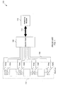
Fig. 2 is a schematic representation of asystem 200 for monitoring themachine 102, in accordance with one embodiment of the invention. In one example embodiment of the invention, a pair of afirst sensor 202a and asecond sensor 202b is placed in vicinity of the high speed rotating elements of themachine 102. Similarly, in one example embodiment, a number of other pairs ofsensors 202c-d, 202e-f, and 202g-h may also placed in the vicinity of the same or different high speed rotating elements of themachine 102. Thesensors 202a-h includeprocessors 204a-h having associated memory respectively integrated therewith. For simplicity, when referring to "first sensor," "second," or "sensors," any or all of possible sensors included in embodiments of the invention may be referred to. In example embodiments, thesensors 202a-h, includingprocessors 204a-h, may be smart digital sensors. A smart digital sensor may have numerous capabilities. For example, a smart digital sensor may be capable of storing its own information; simplifies installation, set-up, and calibration of traditionally complex machine sensing techniques, essentially allowing them to operate as "plug and play" sensors. Further, smart digital sensors may be able to embed and execute algorithms or instructions within themselves. In another example, a smart digital sensor may have field device descriptor capabilities, whereby the sensors store and are operable to communicate data containing information about the sensor and its properties. Smart digital sensors may also communicate the health and/or integrity of the machine and/or devices connected to or associated with the machine. Further, smart digital sensors may be capable of supporting various types offield devices 209 connected to themachine 102, for example by monitoring and/or communicating commands. Moreover, a smart digital sensor is capable of accepting data from other sensors, for example other smart digital sensors, and process that acquired data within itself. For example, thefirst sensor 202a may acquire data from thesecond sensor 202b and subsequently analyze the data. In another embodiment, thefirst sensor pair 202a-b may acquire data from one or more of the other sensor pairs 202c-d, 202e-f, and/or 202g-h. In yet another embodiment, one or more of the sensors may communicate local control instructions directly to thefield devices 209 connected to themachine 102, for example actuators, valves, or other mechanical, electromechanical, or electronic control mechanisms operable to alter the operation of the machine. In one example embodiment, thefirst sensor 202a may include a Programmable Logic Device ("PLD"). Examples of programmable logic devices may be a Field Programmable Gate Array ("FPGA"), an Application-Specific Integrated Circuit ("ASIC"), a microprocessor, a Digital Signal Processor ("DSP"), or a Complex Programmable Logic Device ("CPLD"). An FPGA is a type of logic chip that can be programmed to perform different tasks and an ASIC is a chip designed for a particular application. A microprocessor may incorporate all of the functions of a Central Processing Unit ("CPU") on a single Integrated Circuit ("IC"). A DSP may be a specialized microprocessor designed specifically for digital signal processing. A CPLD contains multiple PLD blocks whose inputs and outputs are connected together. - Referring again to
FIG. 2 , thefirst sensor 202a and thesecond sensor 202b are operable to generate sensor data based onvarious machine 102 conditions. This sensed data may be an indication of themachine 102 condition. Hereinafter, the "sensed data" may be interchangeably referred to as an "indication of the machine condition." Themachine 102 conditions may be based on various physical behavior of themachine 102 such as, but not limited to, vibrations, temperature, pressure, position, acceleration, flow, density, levels, and material compositions. In one example embodiment, thesensors 202a-h may sense the vibrations of the high speed rotating elements of themachine 102. However, it is appreciated that various sensors can be used to sense different machine behavior. The different kinds of sensors that may be used are, but not limited to, vibration sensors, temperature sensors, pressure sensors, position sensors, accelerometers, flow sensors, level sensors, density sensors, or material composition sensors. - In one embodiment of the invention, sensors 202 a-h sense machine conditions from the high speed rotating elements of the
machine 102 and/or sense electrical power characteristics, such as phase current or phase voltage. For example, to sense variations in the vibration of the high speed rotating elements of themachine 102, thefirst sensor 202a and thesecond sensor 202b may be positioned orthogonal (90 degrees) to each other in a plane perpendicular to a centerline of themachine 102. In another example embodiment of the invention, however, thefirst sensor 202a and thesecond sensor 202b may be positioned in a plane perpendicular to the centerline of themachine 102 at angles other than the 90 degrees. Known calibration techniques may be applied to account for various sensor positions with respect to the machine. - Further, the
sensors 202a-h are coupled to each other via acommunication trunk 206. In one example embodiment, thecommunication trunk 206 may be a digital, bi-directional, multi-drop, serial-bus communication network used to link isolated field devices, such as controllers, transducers, actuators, and sensors. The bi-directional capability of thecommunication trunk 206 supports communication of the sensed data among thesensors 202a-h at the same time. Further, thecommunication trunk 206 provides a high-speed and time-critical transmission of the sensed data. - In one example embodiment, the
communication trunk 206 may be based on "FOUNDATION Fieldbus" standard. The "FOUNDATION Fieldbus" standard provides for a digital, serial, two-way communications system that may serve as a base-level network in a plant or factory automation environment, for example. In another example embodiment of the invention, thecommunication trunk 206 may be based on the Process Field Bus ("PROFIBUS") standard. The "PROFIBUS" is a standard for field bus communication in automation technology. Variants of the "PROFIBUS" standard may be used to operate sensors and actuators via a centralized controller in production technology and to monitor measuring equipment via a process control system in process engineering. Further, both the "FOUNDATION Fieldbus" and the "PROFIBUS" standards are based on an Open System Interconnection ("OSI") network communication model. The "OSI" model is a logical framework for standards for the network communication. The "OSI" model is an abstract description for layered communications and computer network protocol design. The "OSI" model, as generally described, may divide network architecture into multiple layers, for example seven layers which, from top to bottom, may be the Application, Presentation, Session, Transport, Network, Data-Link, and Physical Layers. Implementation of these or similar standards and similar automation communication techniques, such as DeviceNet or any other smart digital architecture, used in conjunction with thesensors 202a-h provide the ability to sense, process, analyze, and/or communicate data on and between the sensors, as described herein. - Further, in one example embodiment, when the
sensors 202a-h have generated the sensed data, at least one, e.g., thefirst sensor 202a or the first and thesecond sensors 202a-b, among thesensors 202a-h may aggregate data from one or more of theother sensors 202b-h. Thefirst sensor 202a may receive the data over thecommunication trunk 206. - In one example embodiment, if the
first sensor 202a senses the variation in vibrations above a threshold level from any of the aggregated sensed data, then thefirst processor 204a will communicate this variation to ahost system 208 over thecommunication trunk 206. In an example embodiment, thehost system 208 may be a management or an advisory system that provides advisory information about themachine 102's health and faults to an operator of themachine 102. For example, thehost system 108 may display or otherwise transmit information to an operator of the system, to another management or advisory system, record conditions in machine logs for subsequent analysis and reporting, and the like. In another example embodiment, thehost system 208 may be a host controller operable to alter the operating behavior of themachine 102, such as to prevent themachine 102 from incurring or otherwise minimizing the occurrences of any kind of damages due to variations in the vibration above the threshold level. A host controller may perform different control actions to prevent themachine 102 from incurring or otherwise minimizing the occurrences of any kind of damages or faults. The different control actions may include, but not limited to, adjusting control of themachine 102, generating an audio or visual alarm or alert or notification, transmitting or communicating the sensed data or other control signals to an ancillary machine, or any other control system. Further, adjusting controls of themachine 102 may include, but not limited to commands to stop or trip themachine 102, commands to reduce load of themachine 102, commands to reduce the speed of the machine, and commands to send communication to the ancillary machine or any other control system. As used herein, the terms "host system" and "host controller" may be used interchangeably - According to the invention, the
first processor 204a may communicate a control action directly to afield device 209 for controlling themachine 102 locally, for example instead of or in addition to communicating commands to a host controller orhost system 208. In one example embodiment, thefirst sensor 202a may communicate the variation to both thehost system 208 and thefield device 209, however. Thefield device 209 may be any local control device, such as any mechanical, electrical, or electromechanical device operable to adjust or otherwise alter any aspect of machine operation. Examples fielddevices 209 acting as a local control device may be, but not limited to, control valve actuators, inlet guide vane actuator, air louver actuator, bypass valve actuator, fuel control actuators, fuel temperature actuators, lube oil actuators, product flow actuators, or product flow temperature controls. For example, in response to measurements sensed by thesensors 202a-h, the one ormore processor 204a-h may determine one or more control actions responsive to or effecting machine parameters, such as, but not limited to, fuel flow, temperature, bearing temperature, bearing vibration, and/or product inlet/outlet temperature, for example. Thefield device 209 may then control themachine 102 locally. - Referring again to
FIG. 2 , one or more of theprocessors 204a-h may include a digitally configurable algorithm to analyze the sensed data. In one example embodiment, the digitally configurable algorithm may be downloaded in the memory of the processor, such as thefirst processor 204a. In another example embodiment, the digitally configurable algorithm may be embedded in the memory of a programmable logic device. Theprocessors 204a-h may utilize the digitally configurable algorithm to analyze the sensed data, optionally including the aggregated data from other sensors, and thus to determine faults or other behavior occurring in themachine 102. In example embodiments, the sensed data may be analyzed by a frequency domain analysis, a time domain analysis, or a filtered frequency analysis, for example. The frequency domain analysis may be performed using a Fast Fourier Transform ("FFT"). The FFT converts a time domain representation of the signal sensed by the smart digital sensor into a frequency domain representation. The time domain analysis may include analyzing vibration waveforms, orbit shape of the rotating element, DC offset in the sensed data, position of the rotating elements, absolute phase angle, synchronous, and/or non-synchronous analysis. The filtered frequency analysis may include selecting and analyzing parts of the sensed data based on frequency filters. Using at least one of these, or any other analysis methods, on the sensed data, thefirst processors 204a-h may be able to determine different types of faults or other conditions occurring in themachine 102. Example fault types may be, but not limited to, machine imbalance, machine misalignment, machine bearing failure, machine bearing instability, machine thrust bearing failure, machine rub, shaft imbalance, shaft crack, machine mounting anomaly, and fluid induced instability. Further, theprocessors 204a-h may communicate the determined faults to thehost system 208. - Further, in one embodiment of the invention, the one or more of the
processors 204a-h may generate a characterization of the sensed data. The characterization of the sensed data may include, but not limited to, an orbit shape of machine, a full spectrum of machine, a filtered spectrum of machine, a rotor position, a precessional direction, phase angles, or filtered frequency vibration amplitudes. Subsequently, theprocessors 204a-h may communicate the sensed data characterization to thehost system 208 via thecommunication trunk 206. - Referring again to
FIG. 2 , in one example embodiment, thesecond sensor 202b and thefirst sensor 202a are both smart digital sensors. Since, both thefirst processor 204a and thesecond processor 204b analyze their respective data, thesystem 200 may be operably implemented as a redundant and/or distributed system. In the redundant or distributed system, both thefirst processor 204a and thesecond processor 204b can sense and analyze their own data and the data collected fromother sensors 202a-h over thecommunication trunk 206. Further, it will be apparent that there could be multiple smart digital sensors (like thefirst sensor 202a and thesecond sensor 202b) in thesystem 200, such assensors 202c-h, and the multiple smart digital sensors may analyze each other's data to provide additional redundancy and/or distribution of sensing tasks. -
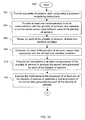
FIG. 3 is a flowchart illustrating one example of amethod 300 for monitoring the machine, according to an embodiment of the invention. Provided is a flow chart illustrating an example of monitoring health of a machine by the sensor. - The example method begins at
block 302. Atblock 302, multiple sensors are installed in the vicinity of high speed rotating elements of the machine. Each sensor is provided with a processor that includes instructions to sense the machine conditions. It is apparent that various sensors can be used to sense various machine conditions. Example sensors that may be used are, but not limited to, a vibration sensor, a temperature sensor, a pressure sensor, a position sensor, an accelerometer, a flow sensor, a level sensor, a density sensor, a material composition sensor, or an electrical power characterization sensor, for example. Further, in one example embodiment, the sensors may be installed in pairs in the vicinity of high speed rotating elements. In one example method, a first sensor and a second sensor in the sensor pair are placed orthogonally (90 degrees) to each other in a plane perpendicular to the machine's centerline. In another example method, the first sensor and the second sensor may be positioned in a plane perpendicular to the centerline of themachine 102 at angles other than the 90 degrees. - Following
block 302 isblock 304, in which a communication trunk is provided. The communication trunk is in communication with sensors installed at the machine. The communication trunk is coupled to each sensor and is operable to communicate the sensed data between the sensors. - Following
block 304 isblock 306, in which one or more of the sensors installed on the machine senses the machine conditions. The machine conditions are based on the various physical machine behaviors and conditions, such as, but not limited to, vibrations, temperature, pressure, position, acceleration, flow, density, levels, material compositions of machine throughput, and/or electrical power characteristics, such as phase current or phase voltage, of the machine. - Following
block 306 isblock 308, in which each sensor generates the sensor data associated with the machine condition. Each sensor senses the variations in the physical machine behaviors and conditions associated with the machine and corresponding to that variation generates electrical signal which forms the sensed data. - Following
block 308 isblock 310, in which a first processor in one of the sensor executes a set of instructions to analyze the sensed data generated by each of the sensors installed at the machine. The instructions may be in the form of digital configurable algorithm which may be embedded or downloaded into memory of the processor. In one example method, the processor first aggregates the sensed data from all the sensors over the communication trunk. After aggregating the data from all the sensors, the first processor analyzes the data, such as by: frequency domain analysis, time domain analysis, and/or filtered frequency component analysis, for example. The frequency domain analysis which may be performed using FFT. The FFT converts a time domain representation of the sensed data by the smart digital sensor into a frequency domain representation. Time domain analysis may include analyzing vibration waveforms, orbit shape of the rotating element, DC offset in the sensed data, position of the rotating elements, absolute phase angle, and/or synchronous and non synchronous analysis. Filtered frequency analysis may include selecting and analyzing parts of the sensed data based on frequency filters. - In one aspect of an example method embodiment, the second sensor and the first sensor are smart digital sensors. Therefore, both the first processor and a second processor included in the second sensor analyze their respective data, providing a method of analyzing machine conditions using a redundant and/or a distributed system. In this case, both the first processor and the second processor sense and analyze their own data and the data collected from the other sensors over the communication trunk. Further, it will be apparent to a person of ordinary skill in the art that there could be multiple smart digital sensors and the multiple smart digital sensors may analyze each other's data.
- Following
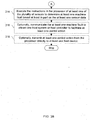
block 310 isblock 312, in which the first processor executes a set of instructions to generate a characterization of the sensed data. The characterization of the sensed data may include, but is not limited to, an orbit shape of machine, a full spectrum of machine, a filtered spectrum of machine, a rotor position, a precessional direction, phase angles, and/or filtered frequency vibration amplitudes. - Following
block 312 isblock 314, in which the first processor executes a set of instructions to determine faults in the machine. Various faults that could be determined may be, but are not limited to, machine imbalance, machine misalignment, machine bearing failure, machine bearing instability, machine thrust bearing failure, machine rub, shaft imbalance, shaft crack, machine mounting anomaly, fluid induced instability, and specific electrical machine faults, such as air gap excursions, shorted rotor bars, loose rotor bars, axial float/magnetic-center excursions, or phasing anomalies, for example. It is appreciated, however, that the fault types will differ depending upon the type of machine and/or the machine characteristics and behavior being sensed. - Following
block 314 isblock 316, in which the machine fault is optionally communicated to a host system or a host controller to facilitate the host system to take a control action. The fault is communicated to the host system over the communication trunk. In an example method, the host system is management or advisory system that provides advisory information about the machine's and faults to an operator of the machine. - Following
block 316 isblock 318, in which the processor optionally transmits control actions to a field device for controlling any aspect or aspect(s) of the machine operation locally. In one example, the processor may transmit one or more control actions to the field device over the communication trunk. In one embodiment, the no additional analysis is necessary at the field device level before controlling the one or more aspects of machine operation. - In another aspect of an example method embodiment, the host system is a host controller that is operable to generate a control action for controlling the operation of the machine, such as to prevent the machine from any kind of faults due to variation in the physical conditions above a threshold level. The host system or controller may generate various types of control actions such as, but not limited to, adjusting control of the machine, generating an audio or visual alarm or alert notification, or transmitting or communicating the sensed data and/or other control signals to an ancillary machine or any other control system.
- Embodiments of the invention are described above with reference to block diagrams and schematic illustrations of methods and systems according to embodiments of the invention. It will be understood that each block of the diagrams and combinations of blocks in the diagrams can be implemented by program instructions or logic. These instructions may be loaded onto one or more general purpose processor, or other programmable data processing apparatus, such as a general purpose or special purpose computer, to produce machines such that the instructions which execute on the computers or other programmable data processing apparatus create means for implementing the functions specified in the block or blocks. Such instructions may also be stored in a processor-readable memory that can direct a programmable data processing apparatus to function in a particular manner, such that the instructions stored in the processor-readable memory produce an article of manufacture including instruction means that implement the function specified in the block or blocks.
- While the invention has been described in connection with what is presently considered to be the most practical and various embodiments, it is to be understood that the invention is not to be limited to the disclosed embodiments, but on the contrary, is intended to cover various modifications and equivalent arrangements included within the scope of the appended claims.
- This written description uses examples to disclose the invention, including the preferred mode, and also to enable any person skilled in the art to practice the invention, including making and using any devices or systems and performing any incorporated methods. The patentable scope the invention is defined in the claims, and may include other examples that occur to those skilled in the art. Such other examples are intended to be within the scope of the claims if they have structural elements that do not differ from the literal language of the claims, or if they include equivalent structural elements with insubstantial differences from the literal languages of the claims.
Claims (11)
- A system (200) for monitoring a machine (102), comprising:a first sensor (202a) comprising a first processor (204a);a second sensor (202b) comprising a second processor (204b); andat least one communication trunk (206) in communication with the first sensor (202a) and the second sensor (202b), and operable to communicate sensor data between each of the first processor (204a) and the second processor (204b);wherein the first sensor (202a) and the second sensor (202b) are operable to generate sensor data associated with at least one machine condition; andwherein the first processor (204a) or the second processor (204b) is operable to:analyze sensor data generated by each of the first sensor (202a) and the second sensor (202b);determine at least one machine fault based at least in part on the analyzed sensor data; and characterised in that the first sensor (202a) and the second (202b) are operable tocommunicate at least one control action directly to at least one field device (209) associated with the machine (102).
- The system (200) of claim 1, wherein the first processor (204a) or the second processor (204b) are operable to analyze sensor data generated by each of the first sensor (202a) and the second sensor (202b) based on a at least one of: a machine orbit shape, a machine full spectrum, a machine filtered spectrum, or a rotor position.
- The system (200) of any preceding claim, wherein the at least one machine fault comprises at least one of: a machine imbalance, a machine misalignment, machine bearing failure, a machine bearing instability, a machine thrust bearing failure, a machine rub, a shaft imbalance, a shaft crack, a machine mounting anomaly, or a fluid induced instability.
- The system (200) of any preceding claim, wherein the machine (102) comprises a rotating machine and wherein the first sensor (202a) and the second sensor (202b) comprise a pair of vibration sensors positioned in distinct planes with respect to each other.
- The system (200) of any preceding claim, wherein the first sensor (202a) and the second sensor (202b) each comprise a smart digital sensor.
- The system (200) of any preceding claim, wherein at least one of the first sensor (202a) or the second sensor (202b) comprise a vibration sensor, a temperature sensor, a pressure sensor, a position sensor, an accelerometer, a flow sensor, a level sensor, a density sensor, or a material composition sensor.
- The system (200) of any preceding claim, wherein at least one of the first processor (204a) or the second processor (204b) is further operable to perform at least one of a frequency domain analysis, a time domain analysis, or a filtered frequency analysis on the sensor data generated by each of the first sensor (202a) and the second sensor (202b).
- The system (200) of any preceding claim, wherein at least one of the first processor (204a) or the second processor (204b) is further operable to communicate the at least one machine fault to at least one of a host system (208) or a host controller.
- The system of any preceding claim, wherein both of the first processor (204a) and the second processor (204b) are operable to analyze the at least one machine condition and determine the at least one machine fault.
- The system of any preceding claim, comprising:a plurality of sensors (202), each comprising a processor (204), wherein each of the plurality of sensors (202) is operable to to generate sensor data associated with at least one machine condition;wherein at least one sensor of the plurality of sensors (202) is operable to receive the generated sensor data from at least one other of the plurality of sensors (202) and wherein the processor of the at least one sensor is operable to:aggregate the received sensor data;perform at least one of a frequency domain analysis, a time domain analysis, or a filtered frequency analysis on the aggregated sensor data; anddetermine at least one machine fault based at least in part on the aggregated sensor data.
- A method for monitoring a machine (102), comprising:providing a plurality of sensors (202), each comprising a processor (204) comprising instructions;providing at least one communication trunk (206) in communication with the plurality of sensors (202), and operable to communicate sensor data between each of the plurality of sensors (202);sensing, by each of the plurality of sensors (202), at least one machine condition;generating, by each of the plurality of sensors (202), sensor data associated with the at least one machine condition; andexecuting the instructions in at least one processor of the plurality of sensors (202) to:analyze the sensor data generated by each of the plurality of sensors (202);determine at least one machine fault based at least in part on the at least one sensor data; and characterized in executing the instructions in at least one processor of the plurality of sensors (202) togenerate at least one control action responsive to determining the at least one machine fault; andcommunicate the at least one control action directly to at least one field device (209) associated with the machine (102).
Applications Claiming Priority (1)
| Application Number | Priority Date | Filing Date | Title |
|---|---|---|---|
| US12/247,002 US8049637B2 (en) | 2008-10-07 | 2008-10-07 | Systems and methods for sensor-level machine monitoring |
Publications (3)
| Publication Number | Publication Date |
|---|---|
| EP2175256A2 EP2175256A2 (en) | 2010-04-14 |
| EP2175256A3 EP2175256A3 (en) | 2012-03-28 |
| EP2175256B1 true EP2175256B1 (en) | 2016-01-27 |
Family
ID=41467322
Family Applications (1)
| Application Number | Title | Priority Date | Filing Date |
|---|---|---|---|
| EP09171295.0A Not-in-force EP2175256B1 (en) | 2008-10-07 | 2009-09-25 | Systems and methods for sensor-level machine monitoring |
Country Status (5)
| Country | Link |
|---|---|
| US (1) | US8049637B2 (en) |
| EP (1) | EP2175256B1 (en) |
| JP (1) | JP2010101883A (en) |
| CN (1) | CN101713673B (en) |
| DK (1) | DK2175256T3 (en) |
Cited By (1)
| Publication number | Priority date | Publication date | Assignee | Title |
|---|---|---|---|---|
| DE102018111019B4 (en) | 2018-05-08 | 2023-08-03 | Witzenmann Gmbh | Movable metal component |
Families Citing this family (27)
| Publication number | Priority date | Publication date | Assignee | Title |
|---|---|---|---|---|
| US10145882B2 (en) | 2010-09-24 | 2018-12-04 | Infineon Technologies Ag | Sensor self-diagnostics using multiple signal paths |
| US9874609B2 (en) | 2010-09-24 | 2018-01-23 | Infineon Technologies Ag | Sensor self-diagnostics using multiple signal paths |
| DE202010016974U1 (en) * | 2010-12-27 | 2011-03-03 | Lincoln Gmbh | lubricant distributors |
| US10442065B2 (en) * | 2011-05-23 | 2019-10-15 | Illinois Tool Works Inc. | Stud miss indicator for fastener driving tool |
| WO2013102202A1 (en) * | 2011-12-31 | 2013-07-04 | Aktiebolaget Skf | Systems and methods for energy efficient machine condition monitoring of fans, motors, pumps, compressors and other equipment |
| JP5848164B2 (en) * | 2012-03-05 | 2016-01-27 | 三菱日立パワーシステムズ株式会社 | Bearing test apparatus and control method of bearing test apparatus |
| JP2013228245A (en) * | 2012-04-25 | 2013-11-07 | Toshiba Corp | Vibration measuring system and vibration measuring method |
| US9381635B2 (en) | 2012-06-05 | 2016-07-05 | Illinois Tool Works Inc. | Fastener-driving tool including a fastening result detector |
| CN102937523A (en) * | 2012-11-06 | 2013-02-20 | 昆山北极光电子科技有限公司 | Fan gearbox working condition detection and fault diagnosis system |
| EP2746885A1 (en) * | 2012-12-18 | 2014-06-25 | Alstom Wind, S.L.U. | Method of monitoring the condition of a wind turbine |
| DE102014103556B4 (en) * | 2013-03-15 | 2020-06-18 | Infineon Technologies Ag | Sensor self-diagnosis using multiple signal paths |
| WO2015160791A1 (en) | 2014-04-14 | 2015-10-22 | Dynapar Corporation | Sensor hub comprising a rotation encoder |
| SG10201405714SA (en) * | 2014-09-15 | 2016-04-28 | Yokogawa Engineering Asia Pte Ltd | Method, system and computer program for fault detection in a machine |
| WO2016095873A1 (en) * | 2014-12-19 | 2016-06-23 | Nv Tecnologias S.A. | System and method for the measurement and analysis of condition parameters of a machine |
| DE102015102486B4 (en) * | 2015-02-20 | 2021-01-28 | Krohne Messtechnik Gmbh | Field device for determining a measured variable and method for communication |
| CN106301990A (en) * | 2015-06-09 | 2017-01-04 | 张菁玶 | Machine condition and user behavior analysis system thereof |
| US20170067860A1 (en) * | 2015-09-03 | 2017-03-09 | Paul Grabill | Control Area Network Machine Diagostic |
| TWI607830B (en) | 2016-11-15 | 2017-12-11 | 財團法人工業技術研究院 | Machine tool feed device design system and method thereof |
| US10114061B2 (en) * | 2016-11-28 | 2018-10-30 | Kohler Co. | Output cable measurement |
| US11002634B2 (en) | 2017-08-24 | 2021-05-11 | Banner Engineering Corp | Vibrational alarms facilitated by determination of motor on-off state in variable-duty multi-motor machines |
| TWI665436B (en) * | 2017-11-30 | 2019-07-11 | National Chung Cheng University | Device and method for monitoring healthy status of machinery mount |
| KR101989267B1 (en) * | 2018-01-09 | 2019-06-13 | 한국산업기술대학교산학협력단 | Method of detecting abnormal of a machine and apparatuses performing the same |
| DE102018111024A1 (en) * | 2018-05-08 | 2019-11-14 | Witzenmann Gmbh | Movable component made of metal |
| KR102464187B1 (en) * | 2018-05-31 | 2022-11-07 | 닛본 덴끼 가부시끼가이샤 | Surveillance Systems and Monitoring Methods |
| EP3660607A1 (en) | 2018-11-30 | 2020-06-03 | Siemens Aktiengesellschaft | Method and system of monitoring the operation of at least one drive component |
| EP3809109A1 (en) * | 2019-10-16 | 2021-04-21 | Siemens Aktiengesellschaft | Smart motor data analytics with real-time algorithm |
| CN115326400B (en) * | 2022-10-13 | 2023-04-07 | 中国航发四川燃气涡轮研究院 | Fault diagnosis method of aircraft engine surge detection system and electronic equipment |
Citations (7)
| Publication number | Priority date | Publication date | Assignee | Title |
|---|---|---|---|---|
| US20020171555A1 (en) | 2001-04-05 | 2002-11-21 | Kochersberger Kevin B. | System and method for testing linkages |
| US7019661B2 (en) | 2001-12-18 | 2006-03-28 | Kabushiki Kaisha Teikoku Denki Seisakusyo | Axial bearing wear detection device for canned motor |
| US20060145881A1 (en) | 2001-08-07 | 2006-07-06 | Nsk Ltd. | Wireless sensor, rolling bearing with sensor, management apparatus and monitoring system |
| US20070063859A1 (en) | 2005-08-04 | 2007-03-22 | Siemens Westinghouse Power Corporation | Power generator and power generator auxiliary monitoring |
| US20070152107A1 (en) | 2005-12-23 | 2007-07-05 | Afs-Keystone, Inc. | Railroad train monitoring system |
| US20080074254A1 (en) | 2006-09-07 | 2008-03-27 | Townsend Christopher P | Heat stress, plant stress and plant health monitor system |
| DE102006051102A1 (en) | 2006-10-25 | 2008-04-30 | Endress + Hauser Gmbh + Co. Kg | Process e.g. analytic process, automaton system, has field device providing measuring device-specific measuring and position values as information to remaining devices, where information is provided as process state vector |
Family Cites Families (12)
| Publication number | Priority date | Publication date | Assignee | Title |
|---|---|---|---|---|
| US5528219A (en) * | 1994-04-28 | 1996-06-18 | Konrad Doppelmayr & Sohn | Ropeway safety monitoring system |
| JP3874110B2 (en) * | 2002-08-30 | 2007-01-31 | 日本精工株式会社 | Abnormality diagnosis system |
| US6957157B2 (en) * | 2002-11-12 | 2005-10-18 | Flow Metrix, Inc. | Tracking vibrations in a pipeline network |
| JP2004184166A (en) * | 2002-12-02 | 2004-07-02 | Mitsubishi Heavy Ind Ltd | Monitoring system for bearing unit, and monitoring method for bearing unit |
| JP2006077938A (en) * | 2004-09-13 | 2006-03-23 | Nsk Ltd | Abnormality diagnosing device |
| CN2811952Y (en) * | 2005-06-13 | 2006-08-30 | 夏惠兴 | Online monitoring and protecting device for rotary machinery |
| US7719416B2 (en) * | 2005-09-09 | 2010-05-18 | Microstrain, Inc. | Energy harvesting, wireless structural health monitoring system |
| US8180363B2 (en) * | 2005-11-15 | 2012-05-15 | Sony Computer Entertainment Inc. | Communication apparatus preventing communication interference |
| US7302362B2 (en) * | 2006-03-01 | 2007-11-27 | International Business Machines Corporation | System and method for efficient and collective adjustment of sensor reporting ranges for long-lived queries |
| BRPI0602943B1 (en) * | 2006-06-30 | 2017-05-23 | Brudden Equip | treadmill belt misalignment flag |
| US20080097725A1 (en) | 2006-10-23 | 2008-04-24 | General Electric Company | Monitoring system and method |
| JP2008232934A (en) * | 2007-03-22 | 2008-10-02 | Jfe Advantech Co Ltd | Facility diagnosis system |
-
2008
- 2008-10-07 US US12/247,002 patent/US8049637B2/en not_active Expired - Fee Related
-
2009
- 2009-09-25 EP EP09171295.0A patent/EP2175256B1/en not_active Not-in-force
- 2009-09-25 DK DK09171295.0T patent/DK2175256T3/en active
- 2009-10-01 JP JP2009229166A patent/JP2010101883A/en active Pending
- 2009-10-09 CN CN2009101790285A patent/CN101713673B/en not_active Expired - Fee Related
Patent Citations (7)
| Publication number | Priority date | Publication date | Assignee | Title |
|---|---|---|---|---|
| US20020171555A1 (en) | 2001-04-05 | 2002-11-21 | Kochersberger Kevin B. | System and method for testing linkages |
| US20060145881A1 (en) | 2001-08-07 | 2006-07-06 | Nsk Ltd. | Wireless sensor, rolling bearing with sensor, management apparatus and monitoring system |
| US7019661B2 (en) | 2001-12-18 | 2006-03-28 | Kabushiki Kaisha Teikoku Denki Seisakusyo | Axial bearing wear detection device for canned motor |
| US20070063859A1 (en) | 2005-08-04 | 2007-03-22 | Siemens Westinghouse Power Corporation | Power generator and power generator auxiliary monitoring |
| US20070152107A1 (en) | 2005-12-23 | 2007-07-05 | Afs-Keystone, Inc. | Railroad train monitoring system |
| US20080074254A1 (en) | 2006-09-07 | 2008-03-27 | Townsend Christopher P | Heat stress, plant stress and plant health monitor system |
| DE102006051102A1 (en) | 2006-10-25 | 2008-04-30 | Endress + Hauser Gmbh + Co. Kg | Process e.g. analytic process, automaton system, has field device providing measuring device-specific measuring and position values as information to remaining devices, where information is provided as process state vector |
Non-Patent Citations (4)
| Title |
|---|
| ANONYMOUS: "Bearing Failure Modes-Journal Bearings", STI FIELD APPLI- CATION NOTE, 5 July 2008 (2008-07-05), XP055019751, Retrieved from the Internet <URL:http://www.stiweb.com/appnotes/PDF Files/jbfail.pdf> |
| FRED M. DISCENZO ET AL.: "Intelligent Sensor Modes Enable a New Genera- tion of Machinery Diagnostics and Prognostics", NEW FRONTIERS IN INTE- GRATED DIAGNOSTICS AND PROGNOSTICS. PROCEEDINGS OF THE 55TH MEETING OF THE SOCIETY FOR MACHINERY FAILURE PREVENTION TECHNOLOGY., 2 April 2001 (2001-04-02), Virginia Beach, Virginia, XP055019731 |
| KARL M. REICHARD ET AL.: "Application of sensor fusion and signal classifica- tion techniques in a distributed machinery condition monitoring system", PROCEEDINGS OF SPIE, vol. 4051, 3 April 2000 (2000-04-03), pages 329 - 336, XP055063161, ISSN: 0277-786X |
| KARL M. REICHARD ET AL: "Application of sensor fusion and signal classification techniques in a distributed machinery condition monitoring system</title>", PROCEEDINGS OF SPIE, vol. 4051, 3 April 2000 (2000-04-03), pages 329 - 336, XP055063161, ISSN: 0277-786X, DOI: 10.1117/12.381646 * |
Cited By (1)
| Publication number | Priority date | Publication date | Assignee | Title |
|---|---|---|---|---|
| DE102018111019B4 (en) | 2018-05-08 | 2023-08-03 | Witzenmann Gmbh | Movable metal component |
Also Published As
| Publication number | Publication date |
|---|---|
| EP2175256A2 (en) | 2010-04-14 |
| US20100085205A1 (en) | 2010-04-08 |
| JP2010101883A (en) | 2010-05-06 |
| CN101713673A (en) | 2010-05-26 |
| US8049637B2 (en) | 2011-11-01 |
| DK2175256T3 (en) | 2016-03-29 |
| EP2175256A3 (en) | 2012-03-28 |
| CN101713673B (en) | 2013-08-21 |
Similar Documents
| Publication | Publication Date | Title |
|---|---|---|
| EP2175256B1 (en) | Systems and methods for sensor-level machine monitoring | |
| US11599103B2 (en) | Method and system for data driven machine diagnostics | |
| CN107272586B (en) | Machine learning device, machine learning method, failure prediction device, and failure prediction system | |
| EP3638900B1 (en) | Independent monitoring system for a wind turbine | |
| US7928833B2 (en) | Dynamic condition monitoring system with integrated web server | |
| US20070073521A1 (en) | Machinery Condition Assessment Module | |
| EP1506383B1 (en) | Modular monitoring and protection system with distributed voting logic | |
| FI125797B (en) | Method and equipment for valve condition monitoring | |
| KR20140130538A (en) | Method and system for diagnostic rules for heavy duty gas turbines | |
| WO2003090091A1 (en) | Machine fault information detection and reporting | |
| CH710181A2 (en) | Systems and methods for error analysis. | |
| EP3100125B1 (en) | System and method for verifying the configuration and installation of a monitoring and protection system | |
| US6768949B2 (en) | Modular equipment dynamic condition monitoring system with multiple processors | |
| CN111971631B (en) | Flexible and scalable monitoring system for industrial machines | |
| Ghemari et al. | Incorporating the Time-synchronous Averaging Method into Vibration Analysis Methodologies for the Detection and Localization of Bearing Defects | |
| Kovalyov et al. | Use of the CANopen protocol in vibration control systems of rotary machines | |
| CN112204478B (en) | Monitoring system for an industrial machine having a dynamically adjustable computing unit | |
| Galar et al. | Use of vibration monitoring and analysis as kpis in paper industry | |
| Martin et al. | Integrating vibration, motor current, and wear particle analysis with machine operating state for on-line machinery prognostics/diagnostics systems (MPROS) | |
| Hartley | Field-based systems and advanced diagnostics | |
| Panda et al. | Electronics System Design of Preventive Operation for Industrial Need | |
| Eryurek | Field-based systems and advanced diagnostics | |
| Isaac et al. | Remote Condition Monitoring of Elevator’s Vibration and Acoustics Parameters for Optimized Maintenance Using IoT Technology |
Legal Events
| Date | Code | Title | Description |
|---|---|---|---|
| PUAI | Public reference made under article 153(3) epc to a published international application that has entered the european phase |
Free format text: ORIGINAL CODE: 0009012 |
|
| AK | Designated contracting states |
Kind code of ref document: A2 Designated state(s): AT BE BG CH CY CZ DE DK EE ES FI FR GB GR HR HU IE IS IT LI LT LU LV MC MK MT NL NO PL PT RO SE SI SK SM TR |
|
| PUAL | Search report despatched |
Free format text: ORIGINAL CODE: 0009013 |
|
| AK | Designated contracting states |
Kind code of ref document: A3 Designated state(s): AT BE BG CH CY CZ DE DK EE ES FI FR GB GR HR HU IE IS IT LI LT LU LV MC MK MT NL NO PL PT RO SE SI SK SM TR |
|
| RIC1 | Information provided on ipc code assigned before grant |
Ipc: G01M 15/05 20060101ALI20120222BHEP Ipc: G01M 15/12 20060101ALI20120222BHEP Ipc: G01M 13/04 20060101AFI20120222BHEP |
|
| RIC1 | Information provided on ipc code assigned before grant |
Ipc: G01M 15/12 20060101ALI20120308BHEP Ipc: G01M 15/05 20060101ALI20120308BHEP Ipc: G01M 13/04 20060101AFI20120308BHEP |
|
| 17P | Request for examination filed |
Effective date: 20120928 |
|
| 17Q | First examination report despatched |
Effective date: 20141124 |
|
| REG | Reference to a national code |
Ref country code: DE Ref legal event code: R079 Ref document number: 602009035958 Country of ref document: DE Free format text: PREVIOUS MAIN CLASS: G01M0013040000 Ipc: G05B0023020000 |
|
| RIC1 | Information provided on ipc code assigned before grant |
Ipc: G05B 23/02 20060101AFI20150729BHEP |
|
| GRAP | Despatch of communication of intention to grant a patent |
Free format text: ORIGINAL CODE: EPIDOSNIGR1 |
|
| INTG | Intention to grant announced |
Effective date: 20150911 |
|
| GRAS | Grant fee paid |
Free format text: ORIGINAL CODE: EPIDOSNIGR3 |
|
| GRAA | (expected) grant |
Free format text: ORIGINAL CODE: 0009210 |
|
| AK | Designated contracting states |
Kind code of ref document: B1 Designated state(s): AT BE BG CH CY CZ DE DK EE ES FI FR GB GR HR HU IE IS IT LI LT LU LV MC MK MT NL NO PL PT RO SE SI SK SM TR |
|
| REG | Reference to a national code |
Ref country code: GB Ref legal event code: FG4D |
|
| REG | Reference to a national code |
Ref country code: CH Ref legal event code: EP |
|
| REG | Reference to a national code |
Ref country code: AT Ref legal event code: REF Ref document number: 772983 Country of ref document: AT Kind code of ref document: T Effective date: 20160215 |
|
| REG | Reference to a national code |
Ref country code: IE Ref legal event code: FG4D |
|
| REG | Reference to a national code |
Ref country code: DE Ref legal event code: R096 Ref document number: 602009035958 Country of ref document: DE |
|
| REG | Reference to a national code |
Ref country code: DK Ref legal event code: T3 Effective date: 20160321 |
|
| REG | Reference to a national code |
Ref country code: SE Ref legal event code: TRGR |
|
| REG | Reference to a national code |
Ref country code: LT Ref legal event code: MG4D |
|
| REG | Reference to a national code |
Ref country code: NL Ref legal event code: MP Effective date: 20160127 |
|
| REG | Reference to a national code |
Ref country code: AT Ref legal event code: MK05 Ref document number: 772983 Country of ref document: AT Kind code of ref document: T Effective date: 20160127 |
|
| PG25 | Lapsed in a contracting state [announced via postgrant information from national office to epo] |
Ref country code: NL Free format text: LAPSE BECAUSE OF FAILURE TO SUBMIT A TRANSLATION OF THE DESCRIPTION OR TO PAY THE FEE WITHIN THE PRESCRIBED TIME-LIMIT Effective date: 20160127 |
|
| PG25 | Lapsed in a contracting state [announced via postgrant information from national office to epo] |
Ref country code: HR Free format text: LAPSE BECAUSE OF FAILURE TO SUBMIT A TRANSLATION OF THE DESCRIPTION OR TO PAY THE FEE WITHIN THE PRESCRIBED TIME-LIMIT Effective date: 20160127 Ref country code: FI Free format text: LAPSE BECAUSE OF FAILURE TO SUBMIT A TRANSLATION OF THE DESCRIPTION OR TO PAY THE FEE WITHIN THE PRESCRIBED TIME-LIMIT Effective date: 20160127 Ref country code: NO Free format text: LAPSE BECAUSE OF FAILURE TO SUBMIT A TRANSLATION OF THE DESCRIPTION OR TO PAY THE FEE WITHIN THE PRESCRIBED TIME-LIMIT Effective date: 20160427 Ref country code: ES Free format text: LAPSE BECAUSE OF FAILURE TO SUBMIT A TRANSLATION OF THE DESCRIPTION OR TO PAY THE FEE WITHIN THE PRESCRIBED TIME-LIMIT Effective date: 20160127 Ref country code: GR Free format text: LAPSE BECAUSE OF FAILURE TO SUBMIT A TRANSLATION OF THE DESCRIPTION OR TO PAY THE FEE WITHIN THE PRESCRIBED TIME-LIMIT Effective date: 20160428 Ref country code: IT Free format text: LAPSE BECAUSE OF FAILURE TO SUBMIT A TRANSLATION OF THE DESCRIPTION OR TO PAY THE FEE WITHIN THE PRESCRIBED TIME-LIMIT Effective date: 20160127 |
|
| PG25 | Lapsed in a contracting state [announced via postgrant information from national office to epo] |
Ref country code: PL Free format text: LAPSE BECAUSE OF FAILURE TO SUBMIT A TRANSLATION OF THE DESCRIPTION OR TO PAY THE FEE WITHIN THE PRESCRIBED TIME-LIMIT Effective date: 20160127 Ref country code: IS Free format text: LAPSE BECAUSE OF FAILURE TO SUBMIT A TRANSLATION OF THE DESCRIPTION OR TO PAY THE FEE WITHIN THE PRESCRIBED TIME-LIMIT Effective date: 20160527 Ref country code: PT Free format text: LAPSE BECAUSE OF FAILURE TO SUBMIT A TRANSLATION OF THE DESCRIPTION OR TO PAY THE FEE WITHIN THE PRESCRIBED TIME-LIMIT Effective date: 20160527 Ref country code: AT Free format text: LAPSE BECAUSE OF FAILURE TO SUBMIT A TRANSLATION OF THE DESCRIPTION OR TO PAY THE FEE WITHIN THE PRESCRIBED TIME-LIMIT Effective date: 20160127 Ref country code: LT Free format text: LAPSE BECAUSE OF FAILURE TO SUBMIT A TRANSLATION OF THE DESCRIPTION OR TO PAY THE FEE WITHIN THE PRESCRIBED TIME-LIMIT Effective date: 20160127 Ref country code: LV Free format text: LAPSE BECAUSE OF FAILURE TO SUBMIT A TRANSLATION OF THE DESCRIPTION OR TO PAY THE FEE WITHIN THE PRESCRIBED TIME-LIMIT Effective date: 20160127 |
|
| REG | Reference to a national code |
Ref country code: DE Ref legal event code: R026 Ref document number: 602009035958 Country of ref document: DE |
|
| PLBI | Opposition filed |
Free format text: ORIGINAL CODE: 0009260 |
|
| PG25 | Lapsed in a contracting state [announced via postgrant information from national office to epo] |
Ref country code: EE Free format text: LAPSE BECAUSE OF FAILURE TO SUBMIT A TRANSLATION OF THE DESCRIPTION OR TO PAY THE FEE WITHIN THE PRESCRIBED TIME-LIMIT Effective date: 20160127 |
|
| 26 | Opposition filed |
Opponent name: SCHAEFFLER TECHNOLOGIES AG & CO. KG Effective date: 20161026 |
|
| PG25 | Lapsed in a contracting state [announced via postgrant information from national office to epo] |
Ref country code: CZ Free format text: LAPSE BECAUSE OF FAILURE TO SUBMIT A TRANSLATION OF THE DESCRIPTION OR TO PAY THE FEE WITHIN THE PRESCRIBED TIME-LIMIT Effective date: 20160127 Ref country code: RO Free format text: LAPSE BECAUSE OF FAILURE TO SUBMIT A TRANSLATION OF THE DESCRIPTION OR TO PAY THE FEE WITHIN THE PRESCRIBED TIME-LIMIT Effective date: 20160127 Ref country code: SM Free format text: LAPSE BECAUSE OF FAILURE TO SUBMIT A TRANSLATION OF THE DESCRIPTION OR TO PAY THE FEE WITHIN THE PRESCRIBED TIME-LIMIT Effective date: 20160127 Ref country code: SK Free format text: LAPSE BECAUSE OF FAILURE TO SUBMIT A TRANSLATION OF THE DESCRIPTION OR TO PAY THE FEE WITHIN THE PRESCRIBED TIME-LIMIT Effective date: 20160127 |
|
| PLAX | Notice of opposition and request to file observation + time limit sent |
Free format text: ORIGINAL CODE: EPIDOSNOBS2 |
|
| PG25 | Lapsed in a contracting state [announced via postgrant information from national office to epo] |
Ref country code: BE Free format text: LAPSE BECAUSE OF FAILURE TO SUBMIT A TRANSLATION OF THE DESCRIPTION OR TO PAY THE FEE WITHIN THE PRESCRIBED TIME-LIMIT Effective date: 20160127 |
|
| PG25 | Lapsed in a contracting state [announced via postgrant information from national office to epo] |
Ref country code: BG Free format text: LAPSE BECAUSE OF FAILURE TO SUBMIT A TRANSLATION OF THE DESCRIPTION OR TO PAY THE FEE WITHIN THE PRESCRIBED TIME-LIMIT Effective date: 20160427 Ref country code: SI Free format text: LAPSE BECAUSE OF FAILURE TO SUBMIT A TRANSLATION OF THE DESCRIPTION OR TO PAY THE FEE WITHIN THE PRESCRIBED TIME-LIMIT Effective date: 20160127 |
|
| PLBB | Reply of patent proprietor to notice(s) of opposition received |
Free format text: ORIGINAL CODE: EPIDOSNOBS3 |
|
| PG25 | Lapsed in a contracting state [announced via postgrant information from national office to epo] |
Ref country code: MC Free format text: LAPSE BECAUSE OF FAILURE TO SUBMIT A TRANSLATION OF THE DESCRIPTION OR TO PAY THE FEE WITHIN THE PRESCRIBED TIME-LIMIT Effective date: 20160127 |
|
| REG | Reference to a national code |
Ref country code: CH Ref legal event code: PL |
|
| GBPC | Gb: european patent ceased through non-payment of renewal fee |
Effective date: 20160925 |
|
| REG | Reference to a national code |
Ref country code: IE Ref legal event code: MM4A |
|
| REG | Reference to a national code |
Ref country code: FR Ref legal event code: ST Effective date: 20170531 |
|
| PG25 | Lapsed in a contracting state [announced via postgrant information from national office to epo] |
Ref country code: FR Free format text: LAPSE BECAUSE OF NON-PAYMENT OF DUE FEES Effective date: 20160930 Ref country code: LI Free format text: LAPSE BECAUSE OF NON-PAYMENT OF DUE FEES Effective date: 20160930 Ref country code: IE Free format text: LAPSE BECAUSE OF NON-PAYMENT OF DUE FEES Effective date: 20160925 Ref country code: GB Free format text: LAPSE BECAUSE OF NON-PAYMENT OF DUE FEES Effective date: 20160925 Ref country code: CH Free format text: LAPSE BECAUSE OF NON-PAYMENT OF DUE FEES Effective date: 20160930 |
|
| PG25 | Lapsed in a contracting state [announced via postgrant information from national office to epo] |
Ref country code: LU Free format text: LAPSE BECAUSE OF NON-PAYMENT OF DUE FEES Effective date: 20160925 |
|
| PLBD | Termination of opposition procedure: decision despatched |
Free format text: ORIGINAL CODE: EPIDOSNOPC1 |
|
| PLBP | Opposition withdrawn |
Free format text: ORIGINAL CODE: 0009264 |
|
| REG | Reference to a national code |
Ref country code: DE Ref legal event code: R100 Ref document number: 602009035958 Country of ref document: DE |
|
| PG25 | Lapsed in a contracting state [announced via postgrant information from national office to epo] |
Ref country code: HU Free format text: LAPSE BECAUSE OF FAILURE TO SUBMIT A TRANSLATION OF THE DESCRIPTION OR TO PAY THE FEE WITHIN THE PRESCRIBED TIME-LIMIT; INVALID AB INITIO Effective date: 20090925 Ref country code: CY Free format text: LAPSE BECAUSE OF FAILURE TO SUBMIT A TRANSLATION OF THE DESCRIPTION OR TO PAY THE FEE WITHIN THE PRESCRIBED TIME-LIMIT Effective date: 20160127 |
|
| PLBM | Termination of opposition procedure: date of legal effect published |
Free format text: ORIGINAL CODE: 0009276 |
|
| STAA | Information on the status of an ep patent application or granted ep patent |
Free format text: STATUS: OPPOSITION PROCEDURE CLOSED |
|
| PG25 | Lapsed in a contracting state [announced via postgrant information from national office to epo] |
Ref country code: TR Free format text: LAPSE BECAUSE OF FAILURE TO SUBMIT A TRANSLATION OF THE DESCRIPTION OR TO PAY THE FEE WITHIN THE PRESCRIBED TIME-LIMIT Effective date: 20160127 Ref country code: MT Free format text: LAPSE BECAUSE OF NON-PAYMENT OF DUE FEES Effective date: 20160930 Ref country code: MK Free format text: LAPSE BECAUSE OF FAILURE TO SUBMIT A TRANSLATION OF THE DESCRIPTION OR TO PAY THE FEE WITHIN THE PRESCRIBED TIME-LIMIT Effective date: 20160127 |
|
| 27C | Opposition proceedings terminated |
Effective date: 20180305 |
|
| PGFP | Annual fee paid to national office [announced via postgrant information from national office to epo] |
Ref country code: DE Payment date: 20200819 Year of fee payment: 12 Ref country code: DK Payment date: 20200828 Year of fee payment: 12 |
|
| PGFP | Annual fee paid to national office [announced via postgrant information from national office to epo] |
Ref country code: SE Payment date: 20200826 Year of fee payment: 12 |
|
| REG | Reference to a national code |
Ref country code: DE Ref legal event code: R119 Ref document number: 602009035958 Country of ref document: DE |
|
| REG | Reference to a national code |
Ref country code: DK Ref legal event code: EBP Effective date: 20210930 |
|
| REG | Reference to a national code |
Ref country code: SE Ref legal event code: EUG |
|
| PG25 | Lapsed in a contracting state [announced via postgrant information from national office to epo] |
Ref country code: SE Free format text: LAPSE BECAUSE OF NON-PAYMENT OF DUE FEES Effective date: 20210926 Ref country code: DE Free format text: LAPSE BECAUSE OF NON-PAYMENT OF DUE FEES Effective date: 20220401 |
|
| PG25 | Lapsed in a contracting state [announced via postgrant information from national office to epo] |
Ref country code: DK Free format text: LAPSE BECAUSE OF NON-PAYMENT OF DUE FEES Effective date: 20210930 |