EP2174571A1 - Opening device for a removal guide and catch mechanism - Google Patents
Opening device for a removal guide and catch mechanism Download PDFInfo
- Publication number
- EP2174571A1 EP2174571A1 EP09012755A EP09012755A EP2174571A1 EP 2174571 A1 EP2174571 A1 EP 2174571A1 EP 09012755 A EP09012755 A EP 09012755A EP 09012755 A EP09012755 A EP 09012755A EP 2174571 A1 EP2174571 A1 EP 2174571A1
- Authority
- EP
- European Patent Office
- Prior art keywords
- latching mechanism
- housing
- housing part
- guide
- opening device
- Prior art date
- Legal status (The legal status is an assumption and is not a legal conclusion. Google has not performed a legal analysis and makes no representation as to the accuracy of the status listed.)
- Granted
Links
- 239000012190 activator Substances 0.000 claims abstract description 13
- 230000006835 compression Effects 0.000 claims description 6
- 238000007906 compression Methods 0.000 claims description 6
- 238000013461 design Methods 0.000 claims description 5
- 238000003780 insertion Methods 0.000 description 4
- 230000037431 insertion Effects 0.000 description 4
- 239000000463 material Substances 0.000 description 4
- 230000008878 coupling Effects 0.000 description 3
- 238000010168 coupling process Methods 0.000 description 3
- 238000005859 coupling reaction Methods 0.000 description 3
- 238000004519 manufacturing process Methods 0.000 description 3
- 230000002093 peripheral effect Effects 0.000 description 3
- 239000011324 bead Substances 0.000 description 2
- 238000005452 bending Methods 0.000 description 1
- 238000006243 chemical reaction Methods 0.000 description 1
- 238000011109 contamination Methods 0.000 description 1
- 238000011161 development Methods 0.000 description 1
- 238000009826 distribution Methods 0.000 description 1
- 238000004146 energy storage Methods 0.000 description 1
- 230000007613 environmental effect Effects 0.000 description 1
- 210000003746 feather Anatomy 0.000 description 1
- 230000007257 malfunction Effects 0.000 description 1
- 230000001105 regulatory effect Effects 0.000 description 1
- 238000005096 rolling process Methods 0.000 description 1
- 230000035939 shock Effects 0.000 description 1
- 239000002689 soil Substances 0.000 description 1
- 238000003860 storage Methods 0.000 description 1
- 238000012549 training Methods 0.000 description 1
Images


Classifications
-
- A—HUMAN NECESSITIES
- A47—FURNITURE; DOMESTIC ARTICLES OR APPLIANCES; COFFEE MILLS; SPICE MILLS; SUCTION CLEANERS IN GENERAL
- A47B—TABLES; DESKS; OFFICE FURNITURE; CABINETS; DRAWERS; GENERAL DETAILS OF FURNITURE
- A47B88/00—Drawers for tables, cabinets or like furniture; Guides for drawers
- A47B88/40—Sliding drawers; Slides or guides therefor
- A47B88/453—Actuated drawers
- A47B88/46—Actuated drawers operated by mechanically-stored energy, e.g. by springs
- A47B88/463—Actuated drawers operated by mechanically-stored energy, e.g. by springs self-opening
Definitions
- the present invention relates to an opening device for a pull-out, in particular for drawers, with a guide housing on which a latch is slidable along a guide, wherein the latch is fixed along the guide in two spaced positions and has a receptacle for an activator with a movable rail of the pull-out guide is coupled, and a latching mechanism is provided to fix the latch in a closed position against the force of a spring, and a latching mechanism.
- a pull-out guide is formed from a guide rail fixed to the furniture carcass and a running rail fixed to the pull-out element, as well as, if appropriate, an extending center rail.
- the EP 766939 discloses an opening and closing device for a drawer, in which the back of the drawer, a lever is arranged, which can be fixed to a latching mechanism. For this purpose, the lever is moved along a control cam against the pressure of a spring.
- the spring and the control cam are spaced apart from each other and contacted the spring in the event of engagement end of the drawer.
- control cam and spring to each other Be tuned, especially with regard to the location and arrangement of a drawer in the furniture body.
- the space requirement of the locking mechanism is comparatively large.
- a coupled with a drawer activator with a latch is connectable.
- the latch is guided on a guideway of a housing and can be locked in a closed position of the drawer against the force of a spring.
- the drawer is moved in the opening direction in an unlocking of the latch.
- the guidance of the latch along the guideway to the housing leads just in jerky or jerky movements to considerable material loads. This limits the life, whereby the permanent tensile load of the spring can lead to fatigue.
- the open housing can also affect the contamination of the leadership of the latch.
- the EP 1845821 discloses a pullout guide opening and closing device in which a cam on a track rail is coupled to a latch member which is guided along a latch housing.
- the latch member is coupled to a detent mechanism that can latch the latch member in two spaced apart positions.
- the pawl housing has a guide track on a housing in which a pin of a coupling rod is guided.
- the coupling rod is biased by a spring and coupled at one end to the latch member.
- the latching mechanism has a substantially cylindrically shaped housing with a control cam along which a control element is displaceably guided in a longitudinal direction of the housing and is rotatable about a longitudinal axis.
- a control cam along which a control element is displaceably guided in a longitudinal direction of the housing and is rotatable about a longitudinal axis.
- a rod is movable by the control, which is coupled at the end with the latch,
- a substantially linear movement can be transmitted to the latch, wherein the rod can be guided almost sealed in the housing of the latching mechanism, so that this is particularly protected.
- the mechanism of the latch and the mechanism of the latching mechanism can be provided spaced apart from each other, so that the opening device can be mounted in a furniture carcass even in confined space.
- control may be annular.
- the control may be guided on its outer peripheral surface, wherein at least one radially projecting projection may be provided, which then engages in the control cam. It can also be formed two or more projections, wherein a plurality of contact surfaces of the control cam can provide a guide of the control.
- this can be designed in several parts, wherein a cylindrical housing part is provided, to the at least one outer housing part for training the control cam is at least partially inserted.
- the control cam can be formed by an edge portion which is formed on the inserted part of the outer housing part.
- the inserted portion may be inserted sleeve-shaped in the cylindrical housing part, wherein the edge portion then cooperates with a projection or a plurality of projections on the control.
- an outer housing part is at least partially inserted on each side of the cylindrical housing part.
- the opposite housing parts can form a completely or partially closed control cam on opposite sides.
- a control cam arranged adjacent to the inner wall of the cylindrical housing part is provided on the at least one outer housing part, which cam cooperates with the at least one projection of the control element.
- the cam can be formed thin-walled and be supported on the cylindrical outer housing part, so that a secure guidance of the control is ensured.
- the at least one outer housing part can be locked to the cylindrical housing part.
- an energy accumulator for biasing the latch is provided in the housing.
- the energy accumulator can be supported as a compression spring end to an outer housing part.
- the closed position of the latch is adjustable via the latching mechanism.
- the closed position of the front panel of a drawer can be adjusted accordingly, for example, for a flush alignment.
- an adjustment of the trip path to ensure the function is possible. Due to the manufacturing conditions in furniture large tolerances are accepted in order to achieve high reliability of the opening device can be made adjustable.
- the activator and the latch with the Locking mechanism coupled so that mounting tolerances on the locking mechanism can be compensated.
- at least one housing part which forms a part of the control cam with a latching receptacle, can be adjusted relative to the guide housing of the latching pawl. Because for the adjustment of the latch, it is sufficient if the corresponding locking receptacle of the locking mechanism is adjusted relative to the guide housing.
- a stepless adjustment is made possible, for example, when an outer housing part is adjustable via a thread in the longitudinal direction.
- the energy accumulator can be designed as a compression spring which acts on the latching pawl via the rod arranged in the housing.
- the compression spring can be supported on a disc which is coupled to the rod, so that the rod is guided linearly within the housing. Due to the smaller diameter relative to the control with the radially protruding projections, the control cam does not act on the disc. As a result, the energy storage is largely protected from external environmental influences.
- the opening device does not have to be supplemented by a locking device, which allows cost savings and a very compact design.
- Known from the prior art opening device must be supplemented by a locking mechanism via a tension spring to prevent accidental opening of the drawer.
- the tumbler is via a projection on the control element, which is fixed in the closed position in a locking receptacle of the control cam.
- An end stop is formed via a slot stop on the latch and a slot stop on the guide housing. Regardless, the distance of the front panel relative to the furniture body can be adjusted by the adjusting device to ensure the function of the opening device.
- the housing of the opening device can also be made in one piece, for example with a film hinge. On the other hand, it is conceivable with a lost slot, like a waxy kernel, to work. It is also conceivable to produce the housing from two halves. Other manufacturing methods can be used.
- the locking mechanism according to the invention is preferably used for opening devices for drawer guides, but can also be used for other movable furniture parts, such as flaps or sliding doors.
- the latching mechanism may also have a movable stop, which is not fixedly connected to a latch or the movable furniture part.
- the stop is preferably arranged terminally on the rod of the latching mechanism.
- the latching mechanism can move a movable furniture part from a first to a second position via the movable stop.
- the locking mechanism is used for ejecting movable furniture parts. Possible applications include e.g. also household appliances such as ovens or refrigerators.
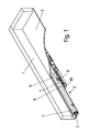
- a drawer 1 is mounted on a pull-out guide 2 slidably mounted on a furniture body, for which purpose a guide rail 3 is fixed to a furniture body (not shown).
- a running rail 4 is slidably held by rolling elements, on which a bottom 5 of the drawer 1 is supported.
- a flat guide housing 6 On the guide rail 3, a flat guide housing 6 is provided, on which a guide 8 is formed in the form of a backdrop-shaped recess. In the guide 8 a latch 7 is guided displaceably. At the latch 7, a receptacle 90 is provided which can be coupled with an activator 9 (driver), which is fixed to the running rail 4.
- an activator 9 driver
- FIG. 2 illustrated opening device is shown on a pull-out, which serves for the storage of drawers, but also for other movable elements, such as shelves, sliding holder or the like can be used.
- the opening device also includes a housing 11 having a latching mechanism to fix the latch 7 in two spaced-apart positions. One of these positions is the closed position in which the detent pawl 7 is locked against the force of a spring.
- the latch 7 is coupled via a rod 10 with the latching mechanism in the housing 11.
- open and close refer to an end position of the drawer 1 in a furniture body in which the drawer is retracted and can be opened or closed accordingly.
- the "closed position” may also be another position in which the component to be fixed is held by the latching mechanism.
- FIG. 3 the latch 7 is shown without the activator 9, which engages in a receptacle 90 on the latch 7, which is formed by two spaced-apart projections 91 and 92.
- the guide 8 on the guide housing 6 has at one end a bent portion 80, on which the latch 7 is pivoted to release the activator 9. From this position, the running rail 4 can be moved to a fully extended position.
- the latch 7 is further locked by a latching mechanism in a closed position of the pull-out or the drawer 1.
- the housing 11 comprises a sleeve-shaped middle housing part 12, to which an outer housing part 13 is attached.
- a sleeve-shaped portion 14 engages with a smaller outer diameter in the sleeve-shaped housing 12 a.
- an edge 15 is formed at the end, which forms part of a control cam.
- the outer housing part 13 has at the portion 14 further projections 16 which are engaged in corresponding recesses 17 on the sleeve-shaped housing 12.
- the locking recesses 24 are used to set the housing 11 to the guide housing 6 by means of locking lugs 25. It is also a force, positive and / or cohesive fixing of the housing 11 to the guide housing 6 conceivable.
- a second outer housing part 20 is provided, which also has a portion 21 with a reduced outer diameter, which is inserted into the sleeve-shaped housing part 12.
- an edge 22 is provided, which also forms part of a control cam.
- projections 23 are further formed, by means of which the housing part 20 can be latched to the sleeve-shaped housing part 12.
- corresponding recesses 18 are provided.
- An inner peripheral wall 19 of the sleeve-shaped housing part 12 surrounds the sections 14 and 21 of the outer housing parts 13 and 20.
- the outer housing part 20 has latching recesses 24 for fixing the housing 11 to the guide housing 6.
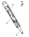
- a rod 10 is provided in the housing 11, the end having a spherical portion 26 which is latched with the latching pawl 7.
- a disc 27 is concentrically fixed to the rod 10, which serves for the end-side support of a spring 28.
- an annular control member 30 is pushed onto the rod 10, which comprises two radially outwardly projecting projections 31.
- the control element 30 is in the housing 12 and rotatably disposed about the rod 10.
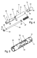
- FIG. 5 the middle sleeve-shaped housing part 12 is shown, in which two each of the inner wall arranged regions of the diametrically opposed control cams 33 are shown, which correspond in their sections 15 and 22 with the sections 15 'and 22' of the housing parts 13 and 20 and thus a form circumferential groove-like cam 33.
- the control cam 33 shown corresponds to the path of movement of the projections 31 on the control element 30 when opening and closing the drawer 1.
- FIG. 6 shows the assembly shown transparently. Thus, the circumferential groove-like cam 33 can be seen.
- FIG. 7 An end portion of the rod 10 with the control 30 is the FIG. 7 again.
- FIG. 8 as well as in the FIG. 11 are the two radial projections 31 on the control 30 recognizable.
- the sectional drawing FIG. 9 gives the view of the bead 37 on the rod 10 and the groove 38 in the control member 30 for rotatable mounting and longitudinal fixation of the control 30 free.
- FIG. 10 An alternative embodiment of the end portion of the rod 10 with the control 30 'is the FIG. 10 again.
- the sectional drawing FIG. 12 gives the view of the spring washer 39 and the groove 44 in the rod 10 for rotatable mounting and longitudinal fixation of the control element 30 'free.
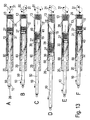
- FIG. 13A the locking position is shown in the closed position, in which the locking mechanism 30 locks the control member 30 against the force of the pressurized spring.
- the control 30 is supported on the disc 27, over which the rod 10, the latch 7, and engaging in position 90 activator 9, and thus the running rail 4 and the drawer 1 is fixed.
- the closed position the radially projecting projections 31 in the pressure spring side remote turning point of a recording at the tips of the protruding portions 15 are held.
- two projections 31 and 31 ' are provided on opposite sides of the control element 30, both of which are fixed in corresponding latching receptacles.
- FIG. 13B In order to release the latching mechanism from the closed position, is accordingly FIG. 13B the drawer 1 and thus on the latch 7 wherein the activator rests on the projection 92, and the rod 10 along its longitudinal axis 50 in the direction of the spring 28 and pushed the spring 28 further compressed.
- the control element 30 When inserting the rod 10, the control element 30 is rotated, since the two projections 31 slide on the flat-inclined side of the section 15 'to the spring 28 facing turning points, which is formed by the edge 15.
- FIG. 13C the drawer 1 is released, due to the spring force, the projections 31 of the control element 30 come to rest on the portion 15 of the control cam 33 but no longer slide back into the locking receptacle 40 at the top of the section 22, but past a tip 41 of the control curve are guided so that the rod 10 is pressed in the opening direction due to the force of the compression spring 28 until the in FIG. 13D shown position is reached.
- the control element 30 bears against a stop 60 which is formed on the housing part 20.
- the stopper 60 may be guided in the sleeve-shaped guide 32, the rod 10, wherein the rod 10 has a smaller diameter than the control element 30.
- the drawer 1 can now be gripped from the slightly open position on the front panel and moved further in the opening direction.
- the latch 7 releases the activator 9 on the running rail 4 due to the arrangement in the bent end portion 80.
- the activator 9 abuts against the projection 92 and via the latch 7, the rod 10 is pressed against the force of the spring 28.
- the control curve Shortly before reaching the fully retracted position of the drawer 1 ( FIG. 13F ), the control curve begins to act on the edge 15 'of the housing part 13 on the radial projections 31, so that the annular control element 30 is rotated about the longitudinal axis 50. Characterized lie in the final position, the projections 31 of the compression spring 28 facing turning points formed by the projections 15 ', opposite locking receptacles 40 at the top of the edges 22 fixed.
- the position of the projections 31 on the control element 30 relative to the longitudinal axis 50 is shown on the right side.
- the control member 30 is not slidably held along the longitudinal axis 50 on the rod 10 but rotatably supported, see FIGS. 7 to 12 , With each opening and closing of the drawer 1, the control 30 rotates, depending on the design of the control cam 33 by a maximum of 180 °. In the exemplary embodiment, the control rotates oscillating by about 120 °. If a plurality of projections 31 or only one projection 31 are provided on the control element 30, the angle of rotation and direction of rotation of the control element 30 can be modified accordingly. In addition, a rotation of the control element 30 is only possible in a rotational direction about the rod 10, so that the control element 30 is moved circumferentially in one or more closing cycles.
- FIGS. 14A and 14B a second embodiment of an opening device is shown in which the latching mechanism is formed modified relative to the first embodiment, wherein the same components are denoted by the same reference numerals.
- this locking mechanism the position of the closed position can be adjusted. It is on the guide housing 6, a housing 11 'is provided, the two relatively adjustable sleeve-shaped housing parts 12' and 20 '.
- the housing part 20 ' is fixedly connected to the guide housing 6, while the housing part 12' is adjustable by turning, as indicated by the arrows.
- an end stop is formed from the insertion stop 36 on the latch 7 and the insertion stop 35 on the guide housing 6.
- FIGS. 15A and 15B the function of adjusting the housing parts 20 'and 12' is shown.
- the position of the sleeve-shaped housing part 12' shifts relative to the stationary housing part 20 '.
- the position of the rod 10 is adjusted to which the latch 7 and according to the drawer 1 is coupled.
- FIG. 16 shows, the fixedly coupled to the guide housing 6 housing part 20 'has a threaded portion 29, whose external thread is in engagement with an internal thread on the housing part 21.
- the housing part 21 ' is latched via one or more projections 23 with the sleeve-shaped housing part 12'.
- the outer housing part 13 with the sleeve-shaped housing part 12 ' is locked.
- the sleeve-shaped housing part 12 ' has on the outer circumference a plurality of ribs 25', which serve to facilitate turning.
- the unit of sleeve-shaped housing part 12', outer housing part 13 and housing part 21 ' moves relative to the fixed housing part 20'.
- the locking receptacle 40 is formed on a sleeve-shaped portion, on which the projections 31 of the annular control element 30 can be fixed.
- the position of the latching receptacle 40 relative to the guide housing 6 is adjusted when turning the sleeve-shaped housing part 12 ', which causes an adjustment of the drawer 1 relative to the surrounding furniture body accordingly.
- the gap between front panel and furniture body can be regulated.
- the gap can be adjusted so that a high reliability for the opening device is achieved.
- the function of the opening device is otherwise formed as in the first embodiment, in particular, the annular control member 30 moves according to the described control curve.
- FIG. 17 is a sectional side view of the housing 11 is shown, wherein the engagement of the sleeve-shaped portions 14 and 21 in the sleeve-shaped housing part 12 are visible.
- a cylindrical guide is formed in the housing 11, which acts as a linear guide for the disk 27 on the rod 10.
- the annular control element 30 can also be rotated about the longitudinal axis 50 via the described control cam 33.
- control cam 33 is formed by two housing parts 13 and 20 which act on the annular control element 30. It is then of course also possible to provide in the sleeve-shaped housing part 12 a recess which passes through the wall of the housing part completely or partially and then forms a control cam for one or more projections 31 of the control elements 30.
Abstract
Description
Die vorliegende Erfindung betrifft eine Öffnungsvorrichtung für eine Ausziehführung, insbesondere für Schubkästen, mit einem Führungsgehäuse, an dem eine Rastklinke entlang einer Führung verschiebbar ist, wobei die Rastklinke entlang der Führung in zwei beabstandeten Positionen fixierbar ist und eine Aufnahme für einen Aktivator aufweist, der mit einer bewegbaren Schiene der Ausziehführung koppelbar ist, und ein Rastmechanismus vorgesehen ist, um die Rastklinke in einer Schließposition gegen die Kraft einer Feder zu fixieren, sowie einen Rastmechanismus.The present invention relates to an opening device for a pull-out, in particular for drawers, with a guide housing on which a latch is slidable along a guide, wherein the latch is fixed along the guide in two spaced positions and has a receptacle for an activator with a movable rail of the pull-out guide is coupled, and a latching mechanism is provided to fix the latch in a closed position against the force of a spring, and a latching mechanism.
Eine Ausziehführung wird aus einer am Möbelkorpus festgelegten Führungsschiene und einer am Auszugselement festgelegten Laufschiene, sowie gegebenenfalls einer auszugsverlängemden Mittelschiene gebildet.A pull-out guide is formed from a guide rail fixed to the furniture carcass and a running rail fixed to the pull-out element, as well as, if appropriate, an extending center rail.
Die
In der
Die
Es ist daher Aufgabe der vorliegenden Erfindung, eine Öffnungsvorrichtung für eine Ausziehführung zu schaffen, die bei einfachem und kompaktem Aufbau nur einen geringen Materialverschleiß besitzt.It is therefore an object of the present invention to provide an opening device for a pull-out, which has a low material wear in a simple and compact design.
Diese Aufgabe wird mit einer Öffnungsvorrichtung für eine Ausziehführung mit den Merkmalen des Anspruches 1 und einem Rastmechanismus mit den Merkmalen des Anspruches 6 gelöst.This object is achieved with an opening device for a pull-out guide with the features of claim 1 and a latching mechanism with the features of
Erfindungsgemäß weist der Rastmechanismus ein im Wesentlichen zylinderformges Gehäuse mit einer Steuerkurve auf, entlang der ein Steuerelement in eine Längsrichtung des Gehäuses verschiebbar und um eine Längsachse drehbar geführt ist. Dadurch kann das Steuerelement in dem Gehäuse entlang der Steuerkurve gleiten, wobei nur geringe Materialbelastungen vorhanden sind. Denn die Steuerkurve kann das Steuerelement leichtgängig führen, da dieses flexibel sowohl verschiebbar als auch drehbar ist, so dass keine Biegebelastungen oder größere Reibungskräfte auftreten können. Zudem ist das Steuerelement in dem Gehäuse geschützt angeordnet, so dass auch Verschmutzungen die Funktion des Rastmechanismuses nicht beeinträchtigen können.According to the invention, the latching mechanism has a substantially cylindrically shaped housing with a control cam along which a control element is displaceably guided in a longitudinal direction of the housing and is rotatable about a longitudinal axis. This allows the control slide in the housing along the control cam, with only low material loads are present. Because the cam can guide the control smoothly, since this is both flexible and rotatable, so that no bending loads or greater frictional forces can occur. In addition, the control is arranged protected in the housing, so that even dirt can not affect the function of the locking mechanism.
Gemäß einer bevorzugten Ausgestaltung der Erfindung ist durch das Steuerelement eine Stange bewegbar, die endseitig mit der Rastklinke gekoppelt ist, Dadurch kann auf die Rastklinke eine im Wesentlichen lineare Bewegung übertragen werden, wobei die Stange nahezu abgedichtet in das Gehäuse des Rastmechanismus geführt sein kann, so dass dieser besonders geschützt angeordnet ist. Zudem kann die Mechanik der Rastklinke und die Mechanik des Rastmechanismuses beabstandet voneinander vorgesehen sein, so dass die Öffnungsvorrichtung auch bei beengtem Bauraum in einem Möbelkorpus montierbar ist.According to a preferred embodiment of the invention, a rod is movable by the control, which is coupled at the end with the latch, Thus, a substantially linear movement can be transmitted to the latch, wherein the rod can be guided almost sealed in the housing of the latching mechanism, so that this is particularly protected. In addition, the mechanism of the latch and the mechanism of the latching mechanism can be provided spaced apart from each other, so that the opening device can be mounted in a furniture carcass even in confined space.
Für eine gute Führung des Steuerelementes kann dieses ringförmig ausgebildet sein. Dadurch kann das Steuerelement an seiner äußeren Umfangsfläche geführt sein, wobei mindestens ein radial hervorstehender Vorsprung vorgesehen sein kann, der dann in die Steuerkurve eingreift. Es können auch zwei oder mehr Vorsprünge ausgebildet sein, wobei mehrere Anlageflächen der Steuerkurve für eine Führung des Steuerelementes sorgen können.For a good guidance of the control this may be annular. Thereby, the control may be guided on its outer peripheral surface, wherein at least one radially projecting projection may be provided, which then engages in the control cam. It can also be formed two or more projections, wherein a plurality of contact surfaces of the control cam can provide a guide of the control.
Für die Möglichkeit einer effektiven Herstellung des Gehäuses mit einer Steuerkurve kann dieses mehrteilig ausgebildet sein, wobei ein zylinderförmiges Gehäuseteil vorgesehen ist, an das mindestens ein äußeres Gehäuseteil zur Ausbildung der Steuerkurve zumindest teilweise eingesteckt ist. Die Steuerkurve kann dabei durch einen Randabschnitt gebildet sein, der an dem eingesteckten Teil des äußeren Gehäuseteils ausgebildet ist. Der eingesteckte Abschnitt kann dabei hülsenförmig in das zylinderförmige Gehäuseteil eingeschoben sein, wobei der Randabschnitt dann mit einem Vorsprung oder mehreren Vorsprüngen an dem Steuerelement zusammenwirkt.For the possibility of effective production of the housing with a control cam, this can be designed in several parts, wherein a cylindrical housing part is provided, to the at least one outer housing part for training the control cam is at least partially inserted. The control cam can be formed by an edge portion which is formed on the inserted part of the outer housing part. The inserted portion may be inserted sleeve-shaped in the cylindrical housing part, wherein the edge portion then cooperates with a projection or a plurality of projections on the control.
Vorzugsweise ist an jeder Seite des zylinderförmigen Gehäuseteils ein äußeres Gehäuseteil zumindest teilweise eingesteckt. Dadurch können die gegenüberliegenden Gehäuseteile eine an gegenüberliegenden Seiten eine ganz oder teilweise geschlossene Steuerkurve bilden.Preferably, an outer housing part is at least partially inserted on each side of the cylindrical housing part. As a result, the opposite housing parts can form a completely or partially closed control cam on opposite sides.
In einer weiteren Ausgestaltung der Erfindung ist an dem mindestens einen äußeren Gehäuseteil eine benachbart zur inneren Wand des zylinderförmigen Gehäuseteils angeordnete Steuerkurve vorgesehen, die mit dem mindestens einen Vorsprung des Steuerelementes zusammenwirkt. Die Steuerkurve kann dünnwandig ausgebildet sein und an dem zylinderförmigen äußeren Gehäuseteil abgestützt sein, so dass eine sichere Führung des Steuerelementes gewährleistet ist.In a further embodiment of the invention, a control cam arranged adjacent to the inner wall of the cylindrical housing part is provided on the at least one outer housing part, which cam cooperates with the at least one projection of the control element. The cam can be formed thin-walled and be supported on the cylindrical outer housing part, so that a secure guidance of the control is ensured.
Für eine effektive Montage kann das mindestens eine äußere Gehäuseteil mit dem zylinderförmigen Gehäuseteil verrastet sein.For an effective assembly, the at least one outer housing part can be locked to the cylindrical housing part.
In einer bevorzugten Ausgestaltung der Erfindung ist in dem Gehäuse ein Kraftspeicher zum Vorspannen der Rastklinke vorgesehen. Der Kraftspeicher kann dabei als Druckfeder endseitig an einem äußeren Gehäuseteil abgestützt sein.In a preferred embodiment of the invention, an energy accumulator for biasing the latch is provided in the housing. The energy accumulator can be supported as a compression spring end to an outer housing part.
Vorzugsweise ist die Schließposition der Rastklinke über den Rastmechanismus verstellbar. Dadurch kann entsprechend auch die Schließposition der Frontblende eines Schubkastens verstellt werden, beispielsweise für eine bündige Ausrichtung. Somit ist eine Justierung des Auslöseweges zur Gewährleistung der Funktion möglich. Aufgrund der Fertigungsgegebenheiten im Möbelbau werden große Toleranzen akzeptiert, um eine hohe Betriebssicherheit der Öffnungsvorrichtung zu erreichen kann diese verstellbar ausgeführt werden. Denn die Frontblende eines Schubkastens ist über die Ausziehführung, den Aktivator und die Rastklinke mit dem Rastmechanismus gekoppelt, so dass Montagetoleranzen über den Rastmechanismus ausgeglichen werden können. Zum Verstellen der Schließposition kann zumindest ein Gehäuseteil, das einen Teil der Steuerkurve mit einer Rastaufnahme ausbildet, relativ zu dem Führungsgehäuse der Rastklinke verstellbar sein. Denn für das Verstellen der Rastklinke reicht es aus, wenn die entsprechende Rastaufnahme des Rastmechanismus relativ zu dem Führungsgehäuse verstellt wird. Eine stufenlose Verstellung wird beispielsweise dann ermöglicht, wenn ein äußeres Gehäuseteil über ein Gewinde in Längsrichtung verstellbar ist.Preferably, the closed position of the latch is adjustable via the latching mechanism. As a result, the closed position of the front panel of a drawer can be adjusted accordingly, for example, for a flush alignment. Thus, an adjustment of the trip path to ensure the function is possible. Due to the manufacturing conditions in furniture large tolerances are accepted in order to achieve high reliability of the opening device can be made adjustable. Because the front panel of a drawer is on the pull-out, the activator and the latch with the Locking mechanism coupled so that mounting tolerances on the locking mechanism can be compensated. To adjust the closing position, at least one housing part, which forms a part of the control cam with a latching receptacle, can be adjusted relative to the guide housing of the latching pawl. Because for the adjustment of the latch, it is sufficient if the corresponding locking receptacle of the locking mechanism is adjusted relative to the guide housing. A stepless adjustment is made possible, for example, when an outer housing part is adjustable via a thread in the longitudinal direction.
Für eine kompakte Ausbildung des Rastmechanismuses kann der Kraftspeicher als Druckfeder ausgebildet sein, die auf die Rastklinke über die in dem Gehäuse angeordnete Stange wirkt. Die Druckfeder kann dabei an einer Scheibe abgestützt sein, die mit der Stange gekoppelt ist, so dass die Stange linear innerhalb des Gehäuses geführt ist. Aufgrund des geringeren Durchmessers gegenüber dem Steuerelement mit den radial hervorstehenden Vorsprüngen wirkt die Steuerkurve nicht auf die Scheibe. Dadurch ist der Kraftspeicher weitgehend vor äußeren Umgebungseinflüssen geschützt.For a compact design of the latching mechanism, the energy accumulator can be designed as a compression spring which acts on the latching pawl via the rod arranged in the housing. The compression spring can be supported on a disc which is coupled to the rod, so that the rod is guided linearly within the housing. Due to the smaller diameter relative to the control with the radially protruding projections, the control cam does not act on the disc. As a result, the energy storage is largely protected from external environmental influences.
Die Öffnungsvorrichtung muss nicht um eine Zuhaltevorrichtung ergänzt werden, was eine Kostenersparnis und eine sehr kompakte Bauweise ermöglicht. Aus dem Stand der Technik bekannte Öffnungsvorrichtung müssen um einen Zuhaltemechanismus über eine Zugfeder ergänzt werden um ein ungewolltes Öffnen des Schubkastens zu vermeiden. Die Zuhaltung erfolgt über einen Vorsprung am Steuerelement, der in der geschlossenen Position in einer Rastaufnahme der Steuerkurve festgelegt wird.The opening device does not have to be supplemented by a locking device, which allows cost savings and a very compact design. Known from the prior art opening device must be supplemented by a locking mechanism via a tension spring to prevent accidental opening of the drawer. The tumbler is via a projection on the control element, which is fixed in the closed position in a locking receptacle of the control cam.
Ein Endanschlag wird über einen Einschubanschlag an der Rastklinke und einem Einschubanschlag an dem Führungsgehäuse gebildet. Unabhängig davon, kann durch die Justiervorrichtung der Abstand der Frontblende gegenüber dem Möbelkorpus eingestellt werden um die Funktion der Öffnungsvorrichtung zu gewährleisten.An end stop is formed via a slot stop on the latch and a slot stop on the guide housing. Regardless, the distance of the front panel relative to the furniture body can be adjusted by the adjusting device to ensure the function of the opening device.
Das Gehäuse der Öffnungsvorrichtung kann auch einteilig, z.B. mit einem Filmscharnier, ausgeführt sein. Zum anderen ist es denkbar mit einem verlorenen Einschub, wie z.B. einem Wachskern, zu arbeiten. Es ist ebenfalls denkbar das Gehäuse aus zwei Hälften zu produzieren. Auch andere Herstellverfahren können eingesetzt werden.The housing of the opening device can also be made in one piece, for example with a film hinge. On the other hand, it is conceivable with a lost slot, like a waxy kernel, to work. It is also conceivable to produce the housing from two halves. Other manufacturing methods can be used.
Der erfindungsgemäße Rastmechanismus wird vorzugsweise für Öffnungsvorrichtungen für Auszugsführungen eingesetzt, kann aber auch für andere bewegbare Möbelteile, wie Klappen oder Schiebetüren verwendet werden. Dabei kann der Rastmechanismus auch einen bewegbaren Anschlag aufweisen, der nicht fest mit einer Rastklinke oder dem bewegbaren Möbelteil verbunden ist. Der Anschlag ist bevorzugt endständig an der Stange des Rastmechanismus angeordnet. Der Rastmechanismus kann über den bewegbaren Anschlag ein bewegliches Möbelteil aus einer ersten in eine zweite Position bewegen. Bevorzugt dient der Rastmechanismus zum Ausstoßen von beweglichen Möbelteilen. Zum möglichen Einsatzgebiet zählen z.B. auch Haushaltsgeräte wie Backöfen oder Kühlgeräte.The locking mechanism according to the invention is preferably used for opening devices for drawer guides, but can also be used for other movable furniture parts, such as flaps or sliding doors. In this case, the latching mechanism may also have a movable stop, which is not fixedly connected to a latch or the movable furniture part. The stop is preferably arranged terminally on the rod of the latching mechanism. The latching mechanism can move a movable furniture part from a first to a second position via the movable stop. Preferably, the locking mechanism is used for ejecting movable furniture parts. Possible applications include e.g. also household appliances such as ovens or refrigerators.
Die Erfindung wird nachfolgend anhand zweier Ausführungsbeispiele mit Bezug auf die beigefügten Zeichnungen näher erläutert. Es zeigen:
- Figur 1
- eine perspektivische Ansicht einer erfindungsgemäßen Öffnungsvorrichtung in der montierten Position;
Figur 2- eine Ansicht der Öffnungsvorrichtung an einer Ausziehführung;
Figur 3- eine perspektivische Ansicht der Öffnungsvorrichtung ohne Ausziehvorrichtung;
Figur 4- eine Explosionsdarstellung der Bauteile des Rastmechanismuses der Öffnungsvorrichtung der
Figur 3 ; Figur 5- eine schematische Ansicht von Elementen der Steuerkurven im Gehäuse;
Figur 6- eine schematische Ansicht der Steuerkurven im Gehäuse;
Figur 7- eine perspektivische Ansicht des Endbereiches der Stange mit dem Steuerelement;
Figur 8- eine Seitenansicht des Endbereiches der Stange mit dem Steuerelement;
Figur 9- eine Schnittansicht gemäß der mit IX bezeichneten Schnittebene in
Figur 8 Figur 10- eine perspektivische Ansicht des Endbereiches der Stange mit dem Steuerelement;
Figur 11- eine Seitenansicht des Endbereiches der Stange mit dem Steuerelement;
Figur 12- eine Schnittansicht gemäß der mit XII bezeichneten Schnittebene in
Figur 11 - Figuren 13A - 13F
- mehrere geschnittene Seitenansichten des Rastmechanismus der Öffnungsvorrichtung in unterschiedlichen Positionen;
- Figuren 14A, 14B
- zwei Ansichten einer zweiten Ausführungsform einer erfindungsgemäßen Öffnungsvorrichtung;
- Figuren 15A, 15B
- zwei Ansichten der Öffnungsvorrichtung der
Figur 7 mit verstelltem Gehäuse; Figur 16- eine geschnittene Ansicht des Gehäuses der Öffnungsvorrichtung der
Figur 7 , und Figur 17- eine geschnittene Ansicht der Gehäuseteile der Öffnungsvorrichtung der
Figur 3
- FIG. 1
- a perspective view of an opening device according to the invention in the mounted position;
- FIG. 2
- a view of the opening device on a pull-out;
- FIG. 3
- a perspective view of the opening device without puller;
- FIG. 4
- an exploded view of the components of the latching mechanism of the opening device of
FIG. 3 ; - FIG. 5
- a schematic view of elements of the cams in the housing;
- FIG. 6
- a schematic view of the cams in the housing;
- FIG. 7
- a perspective view of the end portion of the rod with the control element;
- FIG. 8
- a side view of the end portion of the rod with the control;
- FIG. 9
- a sectional view according to the sectional plane designated by IX in
FIG. 8 ; - FIG. 10
- a perspective view of the end portion of the rod with the control element;
- FIG. 11
- a side view of the end portion of the rod with the control;
- FIG. 12
- a sectional view according to the sectional plane designated by XII in
FIG. 11 ; - FIGS. 13A-13F
- a plurality of sectional side views of the latching mechanism of the opening device in different positions;
- Figures 14A, 14B
- two views of a second embodiment of an opening device according to the invention;
- FIGS. 15A, 15B
- two views of the opening device of
FIG. 7 with adjusted housing; - FIG. 16
- a sectional view of the housing of the opening device of
FIG. 7 , and - FIG. 17
- a sectional view of the housing parts of the opening device of
FIG. 3 ,
Ein Schubkasten 1 ist über eine Ausziehführung 2 verschiebbar an einem Möbelkorpus gelagert, wobei hierfür eine Führungsschiene 3 an einem Möbelkorpus (nicht gezeigt) festgelegt ist. An der Führungsschiene 3 ist eine Laufschiene 4 über Wälzkörper verschiebbar gehalten, auf der ein Boden 5 des Schubkastens 1 abgestützt ist.A drawer 1 is mounted on a pull-
An der Führungsschiene 3 ist ein flaches Führungsgehäuse 6 vorgesehen, an dem eine Führung 8 in Form einer kulissenförmigen Aussparung ausgebildet ist. In der Führung 8 ist eine Rastklinke 7 verschiebbar geführt. An der Rastklinke 7 ist eine Aufnahme 90 vorgesehen, die mit einem Aktivator 9 (Mitnehmer) koppelbar ist, der an der Laufschiene 4 festgelegt ist.On the
Die in
Die Öffnungsvorrichtung umfasst zudem ein Gehäuse 11, das einen Rastmechanismus aufweist, um die Rastklinke 7 in zwei voneinander beabstandeten Positionen zu fixieren. Eine dieser Positionen ist die Schließposition, bei der die Rastklinke 7 gegen die Kraft einer Feder verrastet ist. Die Rastklinke 7 ist dabei über eine Stange 10 mit dem Rastmechanismus in dem Gehäuse 11 gekoppelt.The opening device also includes a
Die Begriffe "öffnen" und "schließen" beziehen sich auf eine Endstellung des Schubkastens 1 in einem Möbelkorpus, in dem der Schubkasten eingefahren ist und entsprechend geöffnet oder geschlossen werden kann. Die "Schließlage" kann jedoch auch eine andere Lage sein, bei der das zu fixierende Bauteil über den Rastmechanismus gehalten ist.The terms "open" and "close" refer to an end position of the drawer 1 in a furniture body in which the drawer is retracted and can be opened or closed accordingly. However, the "closed position" may also be another position in which the component to be fixed is held by the latching mechanism.
In
In
An der gegenüberliegenden Seite des hülsenförmigen Gehäuseteils 12 ist ein zweites äußeres Gehäuseteil 20 vorgesehen, das ebenfalls einen Abschnitt 21 mit reduziertem Außendurchmesser aufweist, der in das hülsenförmige Gehäuseteil 12 eingesteckt ist. An dem Abschnitt 21 ist ein Rand 22 vorgesehen, der ebenfalls Teil einer Steuerkurve bildet. An dem Abschnitt 21 sind ferner Vorsprünge 23 ausgebildet, mittels derer das Gehäuseteil 20 an dem hülsenförmigen Gehäuseteil 12 verrastet werden kann. Hierfür sind entsprechende Aussparungen 18 vorgesehen. Eine innere Umfangswand 19 des hülsenformigen Gehäuseteils 12 umgibt dabei die Abschnitte 14 und 21 der äußeren Gehäuseteile 13 und 20. Der äußere Gehäuseteil 20 weist Rastausnehmungen 24 zur Festlegung des Gehäuses 11 am Führungsgehäuse 6 auf.On the opposite side of the sleeve-shaped
Femer ist eine Stange 10 in dem Gehäuse 11 vorgesehen, die endseitig einen kugelförmigen Abschnitt 26 aufweist, der mit der Rastklinke 7 verrastet ist. An der gegenüberliegenden Seite ist an der Stange 10 eine Scheibe 27 konzentrisch festgelegt, die zur endseitigen Abstützung einer Feder 28 dient. Ferner ist auf der zur Feder 28 gegenüberliegenden Seite der Scheibe 27 ein ringförmiges Steuerelement 30 auf die Stange 10 aufgeschoben, das zwei radial gegenüberliegende nach außen hervorstehende Vorsprünge 31 umfasst. Das Steuerelement 30 ist dabei in dem Gehäuse 12 und um die Stange 10 drehbar angeordnet. Somit ist eine gleichmäßige Kraftverteilung innerhalb der Öffnungsvorrichtung gewährleistet, ein Verkanten oder Verklemmen der Öffnungsvorrichtung wird somit vermieden.Furthermore, a
In
Die
Einen Endabschnitt der Stange 10 mit dem Steuerelement 30 gibt die
Eine alternative Ausführung des Endabschnittes der Stange 10 mit dem Steuerelement 30' gibt die
Die Funktion des Rastmechanismusses wird nachfolgend mit Bezug auf die
In
Um den Rastmechanismus aus der Schließposition zu lösen, wird entsprechend
Nachfolgend wird dann entsprechend
Kurz vor Erreichen der vollständig eingefahrenen Position des Schubkastens 1 (
Bei den in
In den
In den
Wie aus
Das hülsenförmige Gehäuseteil 12' weist am äußeren Umfang mehrere Rippen 25' auf, die zum leichteren Drehen dienen. Wenn das hülsenförmige Gehäuseteil 12' gedreht wird, bewegt sich die Einheit aus hülsenförmigen Gehäuseteil 12', äußere Gehäuseteil 13 und Gehäuseteil 21' relativ zu dem feststehenden Gehäuseteil 20'. An dem Gehäuseteil 21' ist an einem hülsenförmigen Abschnitt die Rastaufnahme 40 ausgebildet, an der die Vorsprünge 31 des ringförmigen Steuerelementes 30 festgelegt werden können. Dadurch wird beim Drehen des hülsenförmigen Gehäuseteils 12' auch die Position der Rastaufnahme 40 relativ zu dem Führungsgehäuse 6 verstellt, was entsprechend eine Verstellung des Schubkastens 1 relativ zu dem umgebenden Möbelkorpus bewirkt. Somit kann der Spalt zwischen Frontblende und Möbelkorpus reguliert werden. Hierdurch kann der Spalt so justiert werden, das eine hohe Betriebssicherheit für die Öffnungsvorrichtung erreicht wird.The sleeve-shaped housing part 12 'has on the outer circumference a plurality of ribs 25', which serve to facilitate turning. When the sleeve-shaped housing part 12 'is rotated, the unit of sleeve-shaped housing part 12',
Die Funktion der Öffnungsvorrichtung ist im Übrigen wie bei dem ersten Ausführungsbeispiel ausgebildet, insbesondere bewegt sich das ringförmige Steuerelement 30 entsprechend der beschriebenen Steuerkurve.The function of the opening device is otherwise formed as in the first embodiment, in particular, the
In
In den dargestellten Ausführungsbeispielen wird die Steuerkurve 33 durch zwei Gehäuseteile 13 und 20 ausgebildet, die auf das ringförmige Steuerelement 30 einwirken. Es ist dann natürlich auch möglich, in dem hülsenförmigen Gehäuseteil 12 eine Aussparung vorzusehen, die die Wand des Gehäuseteils ganz oder teilweise durchgreift und dann eine Steuerkurve für einen oder mehrere Vorsprünge 31 des Steuerelemente 30 bildet.In the illustrated embodiments, the
- 11
- Schubkastendrawer
- 22
- Ausziehführungpull-out
- 33
- Führungsschieneguide rail
- 44
- Laufschienerunner
- 55
- Bodenground
- 66
- Führungsgehäuseguide housing
- 77
- Rastklinkelatch
- 88th
- Führungguide
- 99
- Aktivatoractivator
- 1010
- Stangepole
- 1111
- Gehäusecasing
- 11'11 '
- Gehäusecasing
- 1212
- Hülsenförmiges GehäuseteilSleeve-shaped housing part
- 12'12 '
- Hülsenformiges GehäuseteilSleeve-shaped housing part
- 1313
- Äußeres GehäuseteilOuter housing part
- 1414
- Abschnittsection
- 1515
- Randedge
- 15'15 '
- Randedge
- 1616
- Vorsprunghead Start
- 1717
- Aussparungrecess
- 1818
- Aussparungrecess
- 1919
- Umfangswandperipheral wall
- 2020
- Äußeres GehäuseteilOuter housing part
- 20'20 '
- Äußeres GehäuseteilOuter housing part
- 2121
- Abschnittsection
- 21'21 '
- Gehäuseteilhousing part
- 2222
- Rand / SteuerkurveEdge / control curve
- 2323
- Vorsprunghead Start
- 2424
- Rastausnehmungenrecesses
- 2525
- Rastnasenlocking lugs
- 25'25 '
- Rippenribs
- 2626
- Kugelförmiger AbschnittSpherical section
- 2727
- Scheibedisc
- 2828
- Federfeather
- 2929
- Gewindeabschnittthreaded portion
- 3030
- Steuerelementcontrol
- 3131
- Radialer VorsprungRadial advantage
- 3232
- Führungguide
- 3333
- Steuerkurvecam
- 3434
- Bodenauflagersoil reaction
- 3535
- Einschubanschlaginsertion stop
- 3636
- Einschubanschlaginsertion stop
- 3737
- Wulstbead
- 3838
- Nutgroove
- 3939
- Federscheibespring washer
- 4040
- Rastaufnahmelatching receptacle
- 4141
- Spitzetop
- 4242
- Fanghakenhook
- 4343
- Anlaufschrägestarting slope
- 4444
- Nutgroove
- 5050
- Längsachselongitudinal axis
- 6060
- Anschlagattack
- 8080
- Endabschnittend
- 8181
- Aufnahmeadmission
- 8282
- Vorsprunghead Start
- 8383
- Vorsprunghead Start
Claims (17)
Applications Claiming Priority (1)
| Application Number | Priority Date | Filing Date | Title |
|---|---|---|---|
| DE202008013230U DE202008013230U1 (en) | 2008-10-08 | 2008-10-08 | Opening device for a pull-out guide |
Publications (2)
| Publication Number | Publication Date |
|---|---|
| EP2174571A1 true EP2174571A1 (en) | 2010-04-14 |
| EP2174571B1 EP2174571B1 (en) | 2012-04-18 |
Family
ID=41569891
Family Applications (1)
| Application Number | Title | Priority Date | Filing Date |
|---|---|---|---|
| EP09012755A Active EP2174571B1 (en) | 2008-10-08 | 2009-10-08 | Opening device for a removal guide and catch mechanism |
Country Status (4)
| Country | Link |
|---|---|
| EP (1) | EP2174571B1 (en) |
| AT (1) | ATE553673T1 (en) |
| DE (1) | DE202008013230U1 (en) |
| ES (1) | ES2386235T3 (en) |
Cited By (7)
| Publication number | Priority date | Publication date | Assignee | Title |
|---|---|---|---|---|
| EP2266437A1 (en) * | 2009-06-26 | 2010-12-29 | Paul Hettich GmbH & Co. KG | Opening device for an extending guide and extending guide |
| DE102010017666A1 (en) * | 2010-06-30 | 2012-01-05 | Paul Hettich Gmbh & Co. Kg | detent mechanism |
| DE102011052265A1 (en) | 2010-11-30 | 2012-05-31 | Paul Hettich Gmbh & Co. Kg | Ejector and pullout guide |
| CN104936481A (en) * | 2013-01-23 | 2015-09-23 | 保罗海蒂诗有限及两合公司 | Accelerating device for moveable furniture or domestic-appliance parts |
| AT517603B1 (en) * | 2015-11-20 | 2017-03-15 | Blum Gmbh Julius | Feeding device for movable furniture parts |
| CN107708488A (en) * | 2015-07-07 | 2018-02-16 | 优利思百隆有限公司 | Drive device for movable furniture parts |
| EP3114966B1 (en) * | 2012-01-18 | 2018-06-13 | Julius Blum GmbH | Drive device for a movable furniture part |
Families Citing this family (10)
| Publication number | Priority date | Publication date | Assignee | Title |
|---|---|---|---|---|
| DE202009004769U1 (en) | 2009-01-19 | 2010-06-17 | Paul Hettich Gmbh & Co. Kg | pull-out guide |
| DE102009026142A1 (en) * | 2009-07-09 | 2011-01-13 | Paul Hettich Gmbh & Co. Kg | Detent fitting for a pullout guide |
| DE102010017716A1 (en) * | 2010-07-02 | 2012-01-05 | Paul Hettich Gmbh & Co. Kg | curved guide |
| DE102012100394A1 (en) * | 2012-01-18 | 2013-07-18 | Hettich-Heinze Gmbh & Co. Kg | retraction device |
| DE102012105799A1 (en) * | 2012-06-29 | 2014-01-02 | Paul Hettich Gmbh & Co. Kg | Extract system for extracting e.g. food carriers of refrigerator, has extract guide and ejector held at carrier element, which is mounted at side wall of household appliance or furniture body, where ejector ejects movable thrust element |
| DE202012009762U1 (en) * | 2012-10-12 | 2014-01-21 | Grass Gmbh | Device for opening and closing a movable furniture part |
| AT16876U1 (en) * | 2014-05-23 | 2020-11-15 | Blum Gmbh Julius | Furniture drive |
| AT517063B1 (en) * | 2015-07-07 | 2016-11-15 | Blum Gmbh Julius | Drive device for a movable furniture part |
| DE202015104436U1 (en) | 2015-08-21 | 2016-11-22 | Grass Gmbh | Device for moving a movable furniture part in an opening direction with respect to a furniture body of a piece of furniture |
| DE102020128941A1 (en) | 2020-11-03 | 2022-05-05 | Paul Hettich Gmbh & Co. Kg | drawer guide |
Citations (4)
| Publication number | Priority date | Publication date | Assignee | Title |
|---|---|---|---|---|
| EP0743032A2 (en) | 1995-05-17 | 1996-11-20 | Paul Hettich Gmbh & Co. | Drawer slide |
| EP0766939A2 (en) | 1995-10-03 | 1997-04-09 | ETABLISSEMENTS PIOLE S.A. Société dite | Opening/Closing device of a moving part in relation to a furniture frame and used with movable drawer cabinets |
| DE202005002433U1 (en) * | 2005-02-14 | 2005-05-19 | Grass Gmbh | Touch-latch fitting for furniture with moving parts is fully incorporated into existing moving parts |
| EP1845821A1 (en) | 2004-12-17 | 2007-10-24 | Alfit AG | Closing and opening device for drawers |
Family Cites Families (2)
| Publication number | Priority date | Publication date | Assignee | Title |
|---|---|---|---|---|
| DE102006019351B4 (en) * | 2006-04-24 | 2008-08-28 | Zimmer, Günther | Guidance system with acceleration and deceleration device |
| TWM335193U (en) * | 2007-12-31 | 2008-07-01 | Nan Juen Int Co Ltd | Structure for automatic retractable slide rail of drawer |
-
2008
- 2008-10-08 DE DE202008013230U patent/DE202008013230U1/en not_active Expired - Lifetime
-
2009
- 2009-10-08 AT AT09012755T patent/ATE553673T1/en active
- 2009-10-08 ES ES09012755T patent/ES2386235T3/en active Active
- 2009-10-08 EP EP09012755A patent/EP2174571B1/en active Active
Patent Citations (5)
| Publication number | Priority date | Publication date | Assignee | Title |
|---|---|---|---|---|
| EP0743032A2 (en) | 1995-05-17 | 1996-11-20 | Paul Hettich Gmbh & Co. | Drawer slide |
| EP0766939A2 (en) | 1995-10-03 | 1997-04-09 | ETABLISSEMENTS PIOLE S.A. Société dite | Opening/Closing device of a moving part in relation to a furniture frame and used with movable drawer cabinets |
| EP1845821A1 (en) | 2004-12-17 | 2007-10-24 | Alfit AG | Closing and opening device for drawers |
| EP1845821B1 (en) * | 2004-12-17 | 2008-07-30 | Alfit AG | Closing and opening device for drawers |
| DE202005002433U1 (en) * | 2005-02-14 | 2005-05-19 | Grass Gmbh | Touch-latch fitting for furniture with moving parts is fully incorporated into existing moving parts |
Cited By (13)
| Publication number | Priority date | Publication date | Assignee | Title |
|---|---|---|---|---|
| EP2266437A1 (en) * | 2009-06-26 | 2010-12-29 | Paul Hettich GmbH & Co. KG | Opening device for an extending guide and extending guide |
| DE102010017666A1 (en) * | 2010-06-30 | 2012-01-05 | Paul Hettich Gmbh & Co. Kg | detent mechanism |
| DE102011052265A1 (en) | 2010-11-30 | 2012-05-31 | Paul Hettich Gmbh & Co. Kg | Ejector and pullout guide |
| WO2012072583A1 (en) | 2010-11-30 | 2012-06-07 | Paul Hettich Gmbh & Co. Kg | Ejection device and pull-out guide |
| EP3114966B1 (en) * | 2012-01-18 | 2018-06-13 | Julius Blum GmbH | Drive device for a movable furniture part |
| CN104936481B (en) * | 2013-01-23 | 2017-02-08 | 保罗海蒂诗有限及两合公司 | Accelerating device for moveable furniture or domestic-appliance parts |
| CN104936481A (en) * | 2013-01-23 | 2015-09-23 | 保罗海蒂诗有限及两合公司 | Accelerating device for moveable furniture or domestic-appliance parts |
| CN107708488A (en) * | 2015-07-07 | 2018-02-16 | 优利思百隆有限公司 | Drive device for movable furniture parts |
| JP2018524104A (en) * | 2015-07-07 | 2018-08-30 | ユリウス ブルーム ゲー・エム・ベー・ハーJulius Blum GmbH | Drive for moving furniture parts |
| US10750861B2 (en) | 2015-07-07 | 2020-08-25 | Julius Blum Gmbh | Drive device for a movable furniture part |
| AT517603B1 (en) * | 2015-11-20 | 2017-03-15 | Blum Gmbh Julius | Feeding device for movable furniture parts |
| AT517603A4 (en) * | 2015-11-20 | 2017-03-15 | Blum Gmbh Julius | Feeding device for movable furniture parts |
| US10251481B2 (en) | 2015-11-20 | 2019-04-09 | Julius Blum Gmbh | Slide-in device for moveable furniture parts |
Also Published As
| Publication number | Publication date |
|---|---|
| ATE553673T1 (en) | 2012-05-15 |
| EP2174571B1 (en) | 2012-04-18 |
| DE202008013230U1 (en) | 2010-02-25 |
| ES2386235T3 (en) | 2012-08-14 |
Similar Documents
| Publication | Publication Date | Title |
|---|---|---|
| EP2174571B1 (en) | Opening device for a removal guide and catch mechanism | |
| EP2272400B1 (en) | Locking device and drawer slide | |
| EP2174572B1 (en) | Opening and closing device for a sliding element | |
| EP3429430B1 (en) | Self-closing device and drawer runner | |
| EP3141153B1 (en) | Device for moving a movable furniture part in an opening direction relative to a furniture body of a piece of furniture | |
| EP1817983A1 (en) | Device for influencing the movement of furniture parts moving relative to one another and a drawer guide, as well as a method of producing such a device | |
| EP3199736B1 (en) | Stop damper | |
| DE202015104438U1 (en) | Device for moving a movable furniture part and furniture | |
| DE202008003694U1 (en) | Band for pivotally mounting a wing, a door, a window or the like. on a fixed frame | |
| DE102015114392A1 (en) | Device for positioning two sliding doors and furniture | |
| WO2012110373A1 (en) | Device for locking parts which can be moved relative to one another | |
| WO2017059471A1 (en) | Furniture fitting | |
| EP3518707B1 (en) | Retraction device for a drawer pullout | |
| EP3621484B1 (en) | Holding device for a front panel of a drawer | |
| DE202012005738U1 (en) | Closure for a piece of furniture or a device | |
| EP3769645B1 (en) | Device for moving a movable furniture part in an opening direction relative to the furniture body of a piece of furniture | |
| DE102016122879A1 (en) | magnetic closure | |
| EP3675691B1 (en) | Retraction device for retracting a movable part of an item of furniture or domestic appliance into an end position | |
| WO2011113740A1 (en) | Hinge | |
| DE102015116612A1 (en) | Fitting for a sliding door and method for mounting a sliding door | |
| DE102008051875B4 (en) | Door hinge with lock | |
| EP3955773B1 (en) | Retraction device for a movable part | |
| DE102011000576A1 (en) | Lock for use in locking unit for door, window or cover element, has device for positioning hand tool within lock housing, where hand tool is brought in contact with lock latch shaft | |
| DE4422929C2 (en) | hinge | |
| EP3091317B1 (en) | Household cooler with a bearing unit for a door having a spring element and method for moving a door |
Legal Events
| Date | Code | Title | Description |
|---|---|---|---|
| PUAI | Public reference made under article 153(3) epc to a published international application that has entered the european phase |
Free format text: ORIGINAL CODE: 0009012 |
|
| AK | Designated contracting states |
Kind code of ref document: A1 Designated state(s): AT BE BG CH CY CZ DE DK EE ES FI FR GB GR HR HU IE IS IT LI LT LU LV MC MK MT NL NO PL PT RO SE SI SK SM TR |
|
| AX | Request for extension of the european patent |
Extension state: AL BA RS |
|
| 17P | Request for examination filed |
Effective date: 20100809 |
|
| GRAP | Despatch of communication of intention to grant a patent |
Free format text: ORIGINAL CODE: EPIDOSNIGR1 |
|
| RIN1 | Information on inventor provided before grant (corrected) |
Inventor name: SOBOLEWSKI, UWE Inventor name: SCHAEL, OLIVER Inventor name: HOFFMANN, ANDREAS |
|
| GRAS | Grant fee paid |
Free format text: ORIGINAL CODE: EPIDOSNIGR3 |
|
| GRAA | (expected) grant |
Free format text: ORIGINAL CODE: 0009210 |
|
| AK | Designated contracting states |
Kind code of ref document: B1 Designated state(s): AT BE BG CH CY CZ DE DK EE ES FI FR GB GR HR HU IE IS IT LI LT LU LV MC MK MT NL NO PL PT RO SE SI SK SM TR |
|
| REG | Reference to a national code |
Ref country code: GB Ref legal event code: FG4D Free format text: NOT ENGLISH |
|
| REG | Reference to a national code |
Ref country code: CH Ref legal event code: EP |
|
| REG | Reference to a national code |
Ref country code: IE Ref legal event code: FG4D Free format text: LANGUAGE OF EP DOCUMENT: GERMAN |
|
| REG | Reference to a national code |
Ref country code: AT Ref legal event code: REF Ref document number: 553673 Country of ref document: AT Kind code of ref document: T Effective date: 20120515 |
|
| REG | Reference to a national code |
Ref country code: DE Ref legal event code: R096 Ref document number: 502009003259 Country of ref document: DE Effective date: 20120614 |
|
| REG | Reference to a national code |
Ref country code: NL Ref legal event code: VDEP Effective date: 20120418 |
|
| REG | Reference to a national code |
Ref country code: ES Ref legal event code: FG2A Ref document number: 2386235 Country of ref document: ES Kind code of ref document: T3 Effective date: 20120814 |
|
| LTIE | Lt: invalidation of european patent or patent extension |
Effective date: 20120418 |
|
| PG25 | Lapsed in a contracting state [announced via postgrant information from national office to epo] |
Ref country code: PL Free format text: LAPSE BECAUSE OF FAILURE TO SUBMIT A TRANSLATION OF THE DESCRIPTION OR TO PAY THE FEE WITHIN THE PRESCRIBED TIME-LIMIT Effective date: 20120418 Ref country code: FI Free format text: LAPSE BECAUSE OF FAILURE TO SUBMIT A TRANSLATION OF THE DESCRIPTION OR TO PAY THE FEE WITHIN THE PRESCRIBED TIME-LIMIT Effective date: 20120418 Ref country code: LT Free format text: LAPSE BECAUSE OF FAILURE TO SUBMIT A TRANSLATION OF THE DESCRIPTION OR TO PAY THE FEE WITHIN THE PRESCRIBED TIME-LIMIT Effective date: 20120418 Ref country code: NO Free format text: LAPSE BECAUSE OF FAILURE TO SUBMIT A TRANSLATION OF THE DESCRIPTION OR TO PAY THE FEE WITHIN THE PRESCRIBED TIME-LIMIT Effective date: 20120718 Ref country code: CY Free format text: LAPSE BECAUSE OF FAILURE TO SUBMIT A TRANSLATION OF THE DESCRIPTION OR TO PAY THE FEE WITHIN THE PRESCRIBED TIME-LIMIT Effective date: 20120418 Ref country code: SE Free format text: LAPSE BECAUSE OF FAILURE TO SUBMIT A TRANSLATION OF THE DESCRIPTION OR TO PAY THE FEE WITHIN THE PRESCRIBED TIME-LIMIT Effective date: 20120418 Ref country code: IS Free format text: LAPSE BECAUSE OF FAILURE TO SUBMIT A TRANSLATION OF THE DESCRIPTION OR TO PAY THE FEE WITHIN THE PRESCRIBED TIME-LIMIT Effective date: 20120818 |
|
| PG25 | Lapsed in a contracting state [announced via postgrant information from national office to epo] |
Ref country code: LV Free format text: LAPSE BECAUSE OF FAILURE TO SUBMIT A TRANSLATION OF THE DESCRIPTION OR TO PAY THE FEE WITHIN THE PRESCRIBED TIME-LIMIT Effective date: 20120418 Ref country code: PT Free format text: LAPSE BECAUSE OF FAILURE TO SUBMIT A TRANSLATION OF THE DESCRIPTION OR TO PAY THE FEE WITHIN THE PRESCRIBED TIME-LIMIT Effective date: 20120820 Ref country code: HR Free format text: LAPSE BECAUSE OF FAILURE TO SUBMIT A TRANSLATION OF THE DESCRIPTION OR TO PAY THE FEE WITHIN THE PRESCRIBED TIME-LIMIT Effective date: 20120418 Ref country code: GR Free format text: LAPSE BECAUSE OF FAILURE TO SUBMIT A TRANSLATION OF THE DESCRIPTION OR TO PAY THE FEE WITHIN THE PRESCRIBED TIME-LIMIT Effective date: 20120719 Ref country code: SI Free format text: LAPSE BECAUSE OF FAILURE TO SUBMIT A TRANSLATION OF THE DESCRIPTION OR TO PAY THE FEE WITHIN THE PRESCRIBED TIME-LIMIT Effective date: 20120418 |
|
| PG25 | Lapsed in a contracting state [announced via postgrant information from national office to epo] |
Ref country code: SK Free format text: LAPSE BECAUSE OF FAILURE TO SUBMIT A TRANSLATION OF THE DESCRIPTION OR TO PAY THE FEE WITHIN THE PRESCRIBED TIME-LIMIT Effective date: 20120418 Ref country code: EE Free format text: LAPSE BECAUSE OF FAILURE TO SUBMIT A TRANSLATION OF THE DESCRIPTION OR TO PAY THE FEE WITHIN THE PRESCRIBED TIME-LIMIT Effective date: 20120418 Ref country code: NL Free format text: LAPSE BECAUSE OF FAILURE TO SUBMIT A TRANSLATION OF THE DESCRIPTION OR TO PAY THE FEE WITHIN THE PRESCRIBED TIME-LIMIT Effective date: 20120418 Ref country code: DK Free format text: LAPSE BECAUSE OF FAILURE TO SUBMIT A TRANSLATION OF THE DESCRIPTION OR TO PAY THE FEE WITHIN THE PRESCRIBED TIME-LIMIT Effective date: 20120418 Ref country code: RO Free format text: LAPSE BECAUSE OF FAILURE TO SUBMIT A TRANSLATION OF THE DESCRIPTION OR TO PAY THE FEE WITHIN THE PRESCRIBED TIME-LIMIT Effective date: 20120418 Ref country code: CZ Free format text: LAPSE BECAUSE OF FAILURE TO SUBMIT A TRANSLATION OF THE DESCRIPTION OR TO PAY THE FEE WITHIN THE PRESCRIBED TIME-LIMIT Effective date: 20120418 |
|
| PLBE | No opposition filed within time limit |
Free format text: ORIGINAL CODE: 0009261 |
|
| STAA | Information on the status of an ep patent application or granted ep patent |
Free format text: STATUS: NO OPPOSITION FILED WITHIN TIME LIMIT |
|
| 26N | No opposition filed |
Effective date: 20130121 |
|
| BERE | Be: lapsed |
Owner name: PAUL HETTICH G.M.B.H. & CO. KG Effective date: 20121031 |
|
| REG | Reference to a national code |
Ref country code: DE Ref legal event code: R097 Ref document number: 502009003259 Country of ref document: DE Effective date: 20130121 |
|
| PG25 | Lapsed in a contracting state [announced via postgrant information from national office to epo] |
Ref country code: MC Free format text: LAPSE BECAUSE OF NON-PAYMENT OF DUE FEES Effective date: 20121031 |
|
| REG | Reference to a national code |
Ref country code: IE Ref legal event code: MM4A |
|
| REG | Reference to a national code |
Ref country code: FR Ref legal event code: ST Effective date: 20130628 |
|
| PG25 | Lapsed in a contracting state [announced via postgrant information from national office to epo] |
Ref country code: IE Free format text: LAPSE BECAUSE OF NON-PAYMENT OF DUE FEES Effective date: 20121008 Ref country code: BE Free format text: LAPSE BECAUSE OF NON-PAYMENT OF DUE FEES Effective date: 20121031 Ref country code: BG Free format text: LAPSE BECAUSE OF FAILURE TO SUBMIT A TRANSLATION OF THE DESCRIPTION OR TO PAY THE FEE WITHIN THE PRESCRIBED TIME-LIMIT Effective date: 20120718 |
|
| PG25 | Lapsed in a contracting state [announced via postgrant information from national office to epo] |
Ref country code: FR Free format text: LAPSE BECAUSE OF NON-PAYMENT OF DUE FEES Effective date: 20121031 |
|
| PG25 | Lapsed in a contracting state [announced via postgrant information from national office to epo] |
Ref country code: MT Free format text: LAPSE BECAUSE OF FAILURE TO SUBMIT A TRANSLATION OF THE DESCRIPTION OR TO PAY THE FEE WITHIN THE PRESCRIBED TIME-LIMIT Effective date: 20120418 |
|
| PG25 | Lapsed in a contracting state [announced via postgrant information from national office to epo] |
Ref country code: SM Free format text: LAPSE BECAUSE OF FAILURE TO SUBMIT A TRANSLATION OF THE DESCRIPTION OR TO PAY THE FEE WITHIN THE PRESCRIBED TIME-LIMIT Effective date: 20120418 Ref country code: LU Free format text: LAPSE BECAUSE OF NON-PAYMENT OF DUE FEES Effective date: 20121008 |
|
| REG | Reference to a national code |
Ref country code: CH Ref legal event code: PL |
|
| GBPC | Gb: european patent ceased through non-payment of renewal fee |
Effective date: 20131008 |
|
| PG25 | Lapsed in a contracting state [announced via postgrant information from national office to epo] |
Ref country code: GB Free format text: LAPSE BECAUSE OF NON-PAYMENT OF DUE FEES Effective date: 20131008 Ref country code: LI Free format text: LAPSE BECAUSE OF NON-PAYMENT OF DUE FEES Effective date: 20131031 Ref country code: HU Free format text: LAPSE BECAUSE OF FAILURE TO SUBMIT A TRANSLATION OF THE DESCRIPTION OR TO PAY THE FEE WITHIN THE PRESCRIBED TIME-LIMIT Effective date: 20091008 Ref country code: CH Free format text: LAPSE BECAUSE OF NON-PAYMENT OF DUE FEES Effective date: 20131031 |
|
| PG25 | Lapsed in a contracting state [announced via postgrant information from national office to epo] |
Ref country code: MK Free format text: LAPSE BECAUSE OF FAILURE TO SUBMIT A TRANSLATION OF THE DESCRIPTION OR TO PAY THE FEE WITHIN THE PRESCRIBED TIME-LIMIT Effective date: 20120418 |
|
| REG | Reference to a national code |
Ref country code: DE Ref legal event code: R079 Ref document number: 502009003259 Country of ref document: DE Free format text: PREVIOUS MAIN CLASS: A47B0088040000 Ipc: A47B0088400000 |
|
| REG | Reference to a national code |
Ref country code: DE Ref legal event code: R084 Ref document number: 502009003259 Country of ref document: DE |
|
| REG | Reference to a national code |
Ref country code: ES Ref legal event code: GC2A Effective date: 20200729 |
|
| P01 | Opt-out of the competence of the unified patent court (upc) registered |
Effective date: 20230413 |
|
| PGFP | Annual fee paid to national office [announced via postgrant information from national office to epo] |
Ref country code: TR Payment date: 20230929 Year of fee payment: 15 |
|
| PGFP | Annual fee paid to national office [announced via postgrant information from national office to epo] |
Ref country code: ES Payment date: 20231117 Year of fee payment: 15 |
|
| PGFP | Annual fee paid to national office [announced via postgrant information from national office to epo] |
Ref country code: IT Payment date: 20231031 Year of fee payment: 15 Ref country code: DE Payment date: 20231018 Year of fee payment: 15 Ref country code: AT Payment date: 20231019 Year of fee payment: 15 |