EP2172914A2 - Signal device for signalling an escape route and escape route signalling system - Google Patents
Signal device for signalling an escape route and escape route signalling system Download PDFInfo
- Publication number
- EP2172914A2 EP2172914A2 EP09167881A EP09167881A EP2172914A2 EP 2172914 A2 EP2172914 A2 EP 2172914A2 EP 09167881 A EP09167881 A EP 09167881A EP 09167881 A EP09167881 A EP 09167881A EP 2172914 A2 EP2172914 A2 EP 2172914A2
- Authority
- EP
- European Patent Office
- Prior art keywords
- light sources
- signaling
- escape route
- signaling device
- color
- Prior art date
- Legal status (The legal status is an assumption and is not a legal conclusion. Google has not performed a legal analysis and makes no representation as to the accuracy of the status listed.)
- Ceased
Links
Images


Classifications
-
- G—PHYSICS
- G08—SIGNALLING
- G08B—SIGNALLING OR CALLING SYSTEMS; ORDER TELEGRAPHS; ALARM SYSTEMS
- G08B7/00—Signalling systems according to more than one of groups G08B3/00 - G08B6/00; Personal calling systems according to more than one of groups G08B3/00 - G08B6/00
- G08B7/06—Signalling systems according to more than one of groups G08B3/00 - G08B6/00; Personal calling systems according to more than one of groups G08B3/00 - G08B6/00 using electric transmission, e.g. involving audible and visible signalling through the use of sound and light sources
- G08B7/066—Signalling systems according to more than one of groups G08B3/00 - G08B6/00; Personal calling systems according to more than one of groups G08B3/00 - G08B6/00 using electric transmission, e.g. involving audible and visible signalling through the use of sound and light sources guiding along a path, e.g. evacuation path lighting strip
-
- F—MECHANICAL ENGINEERING; LIGHTING; HEATING; WEAPONS; BLASTING
- F21—LIGHTING
- F21Y—INDEXING SCHEME ASSOCIATED WITH SUBCLASSES F21K, F21L, F21S and F21V, RELATING TO THE FORM OR THE KIND OF THE LIGHT SOURCES OR OF THE COLOUR OF THE LIGHT EMITTED
- F21Y2113/00—Combination of light sources
- F21Y2113/10—Combination of light sources of different colours
- F21Y2113/13—Combination of light sources of different colours comprising an assembly of point-like light sources
-
- F—MECHANICAL ENGINEERING; LIGHTING; HEATING; WEAPONS; BLASTING
- F21—LIGHTING
- F21Y—INDEXING SCHEME ASSOCIATED WITH SUBCLASSES F21K, F21L, F21S and F21V, RELATING TO THE FORM OR THE KIND OF THE LIGHT SOURCES OR OF THE COLOUR OF THE LIGHT EMITTED
- F21Y2115/00—Light-generating elements of semiconductor light sources
- F21Y2115/10—Light-emitting diodes [LED]
Definitions
- the invention relates to a signaling device for signaling an escape route with a plurality of individual light sources, wherein the signaling device is designed to represent a first direction information with a first color in an activated state.
- the invention further relates to a flight path signaling system with this signaling device.
- escape routes which should be used in the event of a fire or other sources of danger of persons identified by appropriate signs or signaling devices.
- signaling devices are permanently illuminated in some embodiments, in other embodiments they are illuminated only when a dangerous situation occurs.
- the publication DE 10 2005 021736 A1 relates, for example, to a device for controlling rescue measures, wherein sensors are arranged in a region accessible to the persons, which locate the person, and wherein the sensors are connected to a computer, which consists of the localization of the person, the properties of the area and the location determined at least one source of danger of rescue operations.
- a rescue measure for example, the evacuation of persons is called, which is implemented in particular by guiding on escape routes, instruction to rescue teams or technical measures, such as closing and opening fire doors.
- the publication EP 1 408 466 A1 relates to a method and a hazard detector for signaling an escape route and is probably the closest prior art.
- the document discloses a danger detector which, in addition to the usual equipment for triggering a hazard alarm, has illuminable arrows pointing away from one another and which can be controlled via a control panel. In the event of danger, the arrow is illuminated, which leads away from the source of danger or corresponds to the current escape route.
- the signaling device according to the invention is suitable for signaling an escape route, and / or formed.
- the signaling device is used to mark the escape route of people from a source of danger, especially from a fire.
- the signal device has a plurality of individual light sources, wherein the individual light sources are preferably arranged at a distance from one another and / or are formed as discrete light sources and / or not as a luminescent screen, in particular not as a TFT or CRT screen.
- the signaling device is realized in such a way that, in an activated state, it represents first direction information with a first color.
- the direction information is designed in such a way that persons searching for the path can read off or derive a direction of travel at the signal device.
- the representation with the first color is made by or on the basis of an active lighting of the individual light sources or a subset thereof.
- the signal device is designed to display a second direction information with a second color, in particular at the same time, in the activated state.
- the second direction information and the second Color are formed analogous to the first directional information and the first color, wherein the first and second color differ in hue.
- the advantage of the invention is that the people searching for a way out can not only be shown a direction that should be used as an escape route.
- This dual function increases the security for those seeking to move away and improves the orientation of the third party in the case of use.
- the first color is green and the second color is red.
- These colors are internationally known as signal colors, so that the people searching for the path intuitively orientate themselves to the direction information with the green color and avoid the direction which is marked by a red color.
- the third parties can specifically use the direction information with the red color.
- the individual light sources are designed as LEDs, in particular high-power LEDs.
- the LEDs can be realized as duo LEDs and / or OLEDs (organic light emitting diodes), it being possible to control two different colors in a single LED.
- duo LEDs two LEDs with different colors can also be positioned spatially adjacent.
- other colors can be added.
- the individual luminous sources can be arranged in any desired form, for example in concentric rings, in a matrix-like manner, wherein optionally only a part of the individual luminous sources is driven to output the direction information.
- the individual light sources are arranged like a ribbon.
- the signaling device is attached so that the extension direction of the band-like arrangement points in or against the escape route.
- a plurality of individual light sources may also be arranged side by side or offset relative to one another transversely to the extension direction.
- the direction information is output statically, so that the signal device is constantly lit in the activated state.
- the direction information may be output dynamically and / or time varying.
- the direction information may be displayed flashing regularly or irregularly.
- the signaling device is designed so that a running light function is implemented in the activated state, the impression is created by a time-controlled activation of the individual luminous sources for the refugees seeking people, one or more light sources would run in a direction corresponding to the first direction information or the second direction information corresponds.
- the signaling device has means for generating a directional radiation of the individual light sources.
- the radiation characteristic is selected such that a part of the individual light sources is directed into a first solid angle region and a second part of the single light sources into a second solid angle region, wherein the first and second solid angle regions are not formed overlapping. Locally, each of the individual sources of light radiates either into the first or the second solid angle range.
- a radiation characteristic wherein e.g.
- the first part of the single luminous sources radiates in a first direction and a second part of the luminous sources radiates in a different direction, wherein the individual beams of the individual luminous sources in the immediate vicinity can indeed intersect, however, at some distance, there are two different solid angle ranges .
- the signal device is designed so that all individual luminous sources, whose emission characteristic in the first solid angle range shows with the one color and that all single luminance sources whose emission characteristic in the second solid angle range shows emitting with the other color.
- the signaling device is formed in this development is such that only the first color and in a different direction only the second color can be seen for the wegsuchenden people in a viewing direction. at This development, it is therefore not necessary to share the signal device, for example, in half and to illuminate the one half with the first color and the second half with the second color. Instead, it is possible that in extreme cases, only the first color or only the second color is shown depending on the position of the escape route searching persons with respect to the signaling device and its viewing direction to the signaling device. In other positions or other directions of view of the escape route seeker, the signal device is divided in terms of position depending on the colors.
- the signal device has light-guiding and / or limiting structures, for example in the cross section through the signal device funnel-like structures, which limit the solid angle of the radiation of the individual light sources.
- this can be integrated in another functional unit, such as a decorative band, a carpet strip, a bumper strip or the like. It is even possible that the signal device is used in the non-activated state for illumination purposes.
- the invention also relates to an escape route signaling system with a signaling device as described above, or according to one of the preceding claims, wherein at least one of the signaling devices is arranged near the ground.
- the emergency exit signaling system has, for example, a security alarm center, which is connected via a fieldbus system or another system with a plurality of hazard sensors and further actuators.
- the hazard sensor signals of the hazard sensors are evaluated and in the case of a dangerous condition, for example, based on in the alarm center deposited escape route plans made a dynamic control of the actuators and the at least one signaling device.
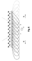
- the FIG. 1 shows a schematic representation of an escape route signaling system 1 for a building, a building complex, public spaces or the like as an embodiment of the invention.
- the escape route signaling system 1 is used to detect a hazard, such as a fire automated or another alarm message and appropriate To implement countermeasures, in particular an evacuation of persons staying in the danger areas. The evacuation takes place, among other things, by issuing directional information to the persons at risk.
- the escape route signaling system 1 comprises a hazard warning center 2, hazard sensors 3, general actuators 4 and signaling devices 5, which are connected to each other by signal technology or via the hazard warning center 2.
- the signaling connection can be realized for example via a fieldbus system.
- the topology of the signaling connection is arbitrary, the hazard sensors 3, the actuators 4 and the signaling device 5 can be controlled via the same fieldbus, alternatively, different fieldbus stitches or - rings can be used. It is also possible to use another form of fieldbus for the hazard sensors 3 and the actuators 4 or the signal device 5.
- the security control center 2 has a storage device 6, in which an escape route plan is stored, so that the security control center 6 is designed for dynamic activation of the actuators 4 and signal devices 5.
- the signaling devices 5 are intended to provide the refugees with information on the basis of optical signals in which direction they should go in order to safely leave the object, for example the building.
- FIG. 2 shows a schematic three-dimensional representation of a room with a signaling device 5 as an embodiment of the invention, which is controlled by the escape route signaling system 1.
- a person looking for the escape route 7 is shown standing on the floor 8, which looks at the signaling device 5.
- the signaling device 5 is formed as a band and implemented in this embodiment as a design or impact protection strip.
- a plurality of individual light sources 9, 9a, 9b are integrated, which are arranged side by side in the extension direction of the signal device 5.
- the individual light sources 9, 9a, 9b are used to display an escape direction 10 and an opposite direction 11.
- the escape direction 10 and the opposite direction 11 can be displayed by a in the FIG. 2 the left part of the individual luminous sources 9a is illuminated green and a right part of the individual luminous sources 9b is illuminated red. Due to the signal colors green and red white the person 7 intuitively that the escape route according to arrow 10 by the green single light sources 9a and the route to the sources of danger according to arrow 11 and / or in a non-recommended area by the red single light sources 9b is displayed.
- FIG. 3a illustrates as a table, the table according to FIG. 3 a signaling the route in the direction of arrow 11 and the FIG. 3b the signaling of the path in the direction of arrow 10 represents.
- FIG. 3a "runs" a light source in the FIG. 2 to the right, by switching the activation of the individual light sources 9b so that the "current light source” is activated in a time step 1 in the position outside left. In a time step 2, this position is deactivated and the adjacent one to the right is activated.
- the position of the "running light source” is again shifted by one position to the right, etc.
- the light source apparently "runs" to the left.
- the red single luminous sources 9b according to the logic of FIG. 3a and the green single luminous sources 9a according to the logic of FIG. 3b driven.
- individual light sources 9a, 9b of one color are operated statically and those of the other color are operated dynamically.
- the individual light sources 9a are operated like a running light and are controlled statically in the opposite direction 11.
- FIG. 4 shows a development of the embodiment, as for example in the signaling device 5 of FIG. 2 can be used, in a sectional view from above through the signaling device 5, wherein the individual light sources 9a, b are each shown as LEDs.
- Each of the individual light sources 9a, b is arranged in a shaft 12, which is designed such that the radiation of the individual light sources 9a, b is limited in each case to a solid angle range ⁇ 45 °, preferably ⁇ 30 °.
- the solid angle range restriction is preferably performed only in one to the bottom 8 ( FIG. 2 ) parallel plane.
- the solid angles are oriented so that all individual luminous sources 9b with a red color in the direction of escape 10 and single luminous sources 9a with a green color in the opposite direction 11 shine.
- the individual light sources 9a, b designed as duo LEDs, for example, are switched in color so that the individual light sources 9b are green and the individual light sources 9a are red.
- two individual light sources 9 with different colors or equally oriented wells 12 with individual light sources 9 with different colors may be provided.
- FIGS. 5a and 5b are the single luminous sources 9b and 9a shown in a highly schematic representation, wherein the radiation characteristic is illustrated as clubs.
- the limits of the lobes are defined, for example, by the fall in maximum light intensity to 50%.
- the lobe of the single luminous source 9b is oriented in the escape direction 10 and the lobe of the single luminous source 9a in the opposite direction 11.
- a band-like, alternating stringing together of the individual light sources 9b and 9a results in a Rescueabstrahl characterizing as schematized in plan view in the FIG. 6 is shown.
- escape route direction 10 the person 7 sees in the sighting area I only the green individual light sources 9a.
- the opposite direction 11 in the viewing direction range II the person 7 only sees the red individual light sources 9b.
Abstract
Description
Die Erfindung betrifft eine Signaleinrichtung zur Signalisierung eines Fluchtweges mit einer Mehrzahl von Einzelleuchtquellen, wobei die Signaleinrichtung ausgebildet ist, in einem aktivierten Zustand eine erste Richtungsinformation mit einer ersten Farbe darzustellen. Die Erfindung betrifft im Weiteren ein Flugwegsignalisierungssystem mit dieser Signaleinrichtung.The invention relates to a signaling device for signaling an escape route with a plurality of individual light sources, wherein the signaling device is designed to represent a first direction information with a first color in an activated state. The invention further relates to a flight path signaling system with this signaling device.
In größeren Gebäuden ist es üblich oder sogar vorgeschrieben, dass Fluchtwege, welche für den Fall eines Feuer oder einer anderen Gefahrenquellen von Personen genutzt werden sollen, durch entsprechende Hinweistafeln oder Signaleinrichtungen kenntlich gemacht sind. Derartige Signaleinrichtungen sind bei manchen Ausführungen dauerbeleuchtet, bei anderen Ausführungen werden diese erst beleuchtet, sobald eine Gefahrensituation auftritt.In larger buildings, it is common or even required that escape routes, which should be used in the event of a fire or other sources of danger of persons identified by appropriate signs or signaling devices. Such signaling devices are permanently illuminated in some embodiments, in other embodiments they are illuminated only when a dangerous situation occurs.
Die Druckschrift
Die Druckschrift
Im Rahmen der Erfindung wird eine Signaleinrichtung zur Signalisierung eines Fluchtweges mit den Merkmalen des Anspruches 1 sowie ein Fluchtwegsignalisierungssystem mit den Merkmalen des Anspruchs 10 vorgeschlagen. Bevorzugte oder vorteilhafte Ausführungsformen der Erfindung ergeben sich aus den Unteransprüchen der nachfolgenden Beschreibung und den beigefügten Figuren.In the context of the invention, a signaling device for signaling an escape route with the features of
Die Signaleinrichtung gemäß der Erfindung ist zur Signalisierung eines Fluchtweges, geeignet und/oder ausgebildet. Vorzugsweise dient die Signaleinrichtung zur Markierung des Fluchtweges von Personen vor einer Gefahrenquelle, insbesondere vor einem Brand.The signaling device according to the invention is suitable for signaling an escape route, and / or formed. Preferably, the signaling device is used to mark the escape route of people from a source of danger, especially from a fire.
Die Signaleinrichtung weist eine Mehrzahl von Einzelleuchtquellen auf, wobei die Einzelleuchtquellen bevorzugt beabstandet zueinander angeordnet sind und/oder als diskrete Leuchtquellen und/oder nicht als Leuchtschirm, insbesondere nicht als TFT- oder CRT-Bildschirm, ausgebildet sind.The signal device has a plurality of individual light sources, wherein the individual light sources are preferably arranged at a distance from one another and / or are formed as discrete light sources and / or not as a luminescent screen, in particular not as a TFT or CRT screen.
Die Signaleinrichtung ist so realisiert, dass diese in einem aktivierten Zustand eine erste Richtungsinformation mit einer ersten Farbe darstellt. Die Richtungsinformation ist derart ausgebildet, dass wegsuchende Personen an der Signaleinrichtung eine Wegrichtung ablesen oder ableiten können. Die Darstellung mit der ersten Farbe erfolgt durch oder auf Basis eines aktiven Leuchtens der Einzelleuchtquellen bzw. einer Teilmenge davon.The signaling device is realized in such a way that, in an activated state, it represents first direction information with a first color. The direction information is designed in such a way that persons searching for the path can read off or derive a direction of travel at the signal device. The representation with the first color is made by or on the basis of an active lighting of the individual light sources or a subset thereof.
Im Rahmen der Erfindung wird vorgeschlagen, dass die Signaleinrichtung ausgebildet ist, in dem aktivierten Zustand eine zweite Richtungsinformation mit einer zweiten Farbe, insbesondere zeitgleich, darzustellen. Die zweite Richtungsinformation und die zweite Farbe sind analog zu der ersten Richtungsinformation und der ersten Farbe gebildet, wobei sich erste und zweite Farbe im Farbton unterscheiden.In the context of the invention, it is proposed that the signal device is designed to display a second direction information with a second color, in particular at the same time, in the activated state. The second direction information and the second Color are formed analogous to the first directional information and the first color, wherein the first and second color differ in hue.
Der Vorteil der Erfindung ist, dass den wegsuchenden Personen nicht nur eine Richtung aufgezeigt werden kann, die als Fluchtweg genutzt werden soll. Ergänzend zu dieser Funktion ist es möglich, entweder den Wegsuchenden eine Richtung anzuzeigen, in die sie sich nicht begeben sollen, oder Dritten, zum Beispiel Rettungspersonal oder der Feuerwehr, die Richtung zu dem Gefahrenherd zu weisen. Diese Doppelfunktion erhöht die Sicherheit für die wegsuchenden Personen und verbessert die Orientierung der Dritten im Einsatzfall.The advantage of the invention is that the people searching for a way out can not only be shown a direction that should be used as an escape route. In addition to this function, it is possible either to indicate to the evictors a direction in which they should not go, or to point the direction of the danger to others, for example rescue personnel or the fire brigade. This dual function increases the security for those seeking to move away and improves the orientation of the third party in the case of use.
Bei einer besonders bevorzugten Ausführungsform ist die erste Farbe grün und die zweite Farbe rot. Diese Farben sind international als Signalfarben bekannt, so dass sich die wegsuchenden Personen intuitiv an der Richtungsinformation mit der grünen Farbe orientieren und die Richtung, welche durch eine rote Farbe gekennzeichnet ist, meiden werden. Die Dritten können dagegen gezielt die Richtungsinformationen mit der roten Farbe nutzen.In a particularly preferred embodiment, the first color is green and the second color is red. These colors are internationally known as signal colors, so that the people searching for the path intuitively orientate themselves to the direction information with the green color and avoid the direction which is marked by a red color. By contrast, the third parties can specifically use the direction information with the red color.
Bei einer konstruktiven Umsetzung der Erfindung sind die Einzelleuchtquellen als LEDs, insbesondere Hochleistungs-LEDs ausgebildet. Bei einer Weiterbildung können die LEDs als Duo-LEDs und/oder OLEDs (organische Leuchtdioden) realisiert sein, wobei in einer einzigen LEDs zwei unterschiedliche Farben angesteuert werden können. Statt Duo-LEDs können auch jeweils zwei LEDs mit unterschiedlichen Farben räumlich benachbart positioniert werden. Bei anderen Weiterbildungen der Erfindung können weitere Farben aufgenommen werden. Es ist jedoch - nicht zuletzt aus Kostengründen - bevorzugt, wenn die Signaleinrichtung die Richtungsinformationen mit genau zwei Farben ausgibt.In a constructive implementation of the invention, the individual light sources are designed as LEDs, in particular high-power LEDs. In a development, the LEDs can be realized as duo LEDs and / or OLEDs (organic light emitting diodes), it being possible to control two different colors in a single LED. Instead of duo LEDs, two LEDs with different colors can also be positioned spatially adjacent. In other developments of the invention, other colors can be added. However, it is preferred - not least for reasons of cost - if the signaling device outputs the direction information with exactly two colors.
Prinzipiell können die Einzelleuchtquellen in einer beliebigen Form angeordnet sein, zum Beispiel in konzentrischen Ringen, matrixartig etc., wobei zur Ausgabe der Richtungsinformation optional nur ein Teil der Einzelleuchtquellen angesteuert wird. Bei einer bevorzugten Ausführungsform sind die Einzelleuchtquellen bandartig angeordnet. Für den Betrieb wird die Signaleinrichtung so befestigt, dass die Erstreckungsrichtung der bandartigen Anordnung in bzw. gegen den Fluchtweg weist. Bei der bandartigen Ausführungsform können auch mehrere Einzelleuchtquellen quer zur Erstreckungsrichtung nebeneinander oder versetzt zueinander angeordnet sein.In principle, the individual luminous sources can be arranged in any desired form, for example in concentric rings, in a matrix-like manner, wherein optionally only a part of the individual luminous sources is driven to output the direction information. In a preferred embodiment, the individual light sources are arranged like a ribbon. For operation, the signaling device is attached so that the extension direction of the band-like arrangement points in or against the escape route. In the band-like embodiment, a plurality of individual light sources may also be arranged side by side or offset relative to one another transversely to the extension direction.
Es im Rahmen der Erfindung, dass die Richtungsinformationen statisch ausgegeben werden, so dass die Signaleinrichtung im aktivierten Zustand konstant leuchtet. Bei alternativen Ausführungsformen können die Richtungsinformationen dynamisch und/oder zeitvariierend ausgegeben werden. Zum Beispiel können die Richtungsinformationen regelmäßig oder unregelmäßig blinkend dargestellt werden.It is within the scope of the invention that the direction information is output statically, so that the signal device is constantly lit in the activated state. In alternative embodiments, the direction information may be output dynamically and / or time varying. For example, the direction information may be displayed flashing regularly or irregularly.
Bei einer bevorzugten Weiterbildung ist die Signaleinrichtung so ausgebildet, dass im aktivierten Zustand eine Lauflichtfunktion umgesetzt wird, wobei durch ein zeitgesteuertes Aktivieren der Einzelleuchtquellen für die fluchtsuchenden Personen der Eindruck entsteht, eine oder mehrere Lichtquellen würden in eine Richtung laufen, die der ersten Richtungsinformation bzw. der zweiten Richtungsinformation entspricht.In a preferred embodiment, the signaling device is designed so that a running light function is implemented in the activated state, the impression is created by a time-controlled activation of the individual luminous sources for the refugees seeking people, one or more light sources would run in a direction corresponding to the first direction information or the second direction information corresponds.
Bei einer besonders interessanten Umsetzung bzw. Weiterbildung der Erfindung weist die Signaleinrichtung Mittel zur Erzeugung einer gerichteten Abstrahlung der Einzelleuchtquellen auf. Die Abstrahlungscharakteristik ist dabei so gewählt, dass ein Teil der Einzelleuchtquellen in einen ersten Raumwinkelbereich und ein zweiter Teil der Einzelleuchtquellen in einen zweiten Raumwinkelbereich gerichtet ist, wobei erster und zweiter Raumwinkelbereich nicht überlappend ausgebildet sind. Lokal betrachtet strahlt jede der Einzelleuchtquellen entweder in den ersten oder in den zweiten Raumwinkelbereich. In einer Gesamtbetrachtung der Signaleinrichtung ergibt sich eine Abstrahlcharakteristik, wobei z.B. in einer Draufsicht von oben der erste Teil der Einzelleuchtquellen in eine erste Richtung strahlt und ein zweiter Teil der Leuchtquellen in eine andere Richtung strahlt, wobei die Einzelstrahlen der Einzelleuchtquellen in unmittelbarer Nähe sich zwar kreuzen können, es sich in einigem Abstand jedoch zwei verschiedene Raumwinkelbereiche ergeben. Vorzugsweise ist die Signaleinrichtung so ausgebildet, dass alle Einzelleuchtquellen, deren Abstrahlcharakteristik in den ersten Raumwinkelbereich zeigt mit der einen Farbe und dass alle Einzelleuchtquellen, deren Abstrahlcharakteristik in den zweiten Raumwinkelbereich zeigt mit der anderen Farbe abstrahlen.In a particularly interesting implementation or development of the invention, the signaling device has means for generating a directional radiation of the individual light sources. The radiation characteristic is selected such that a part of the individual light sources is directed into a first solid angle region and a second part of the single light sources into a second solid angle region, wherein the first and second solid angle regions are not formed overlapping. Locally, each of the individual sources of light radiates either into the first or the second solid angle range. In an overall view of the signaling device results in a radiation characteristic, wherein e.g. in a plan view from above, the first part of the single luminous sources radiates in a first direction and a second part of the luminous sources radiates in a different direction, wherein the individual beams of the individual luminous sources in the immediate vicinity can indeed intersect, however, at some distance, there are two different solid angle ranges , Preferably, the signal device is designed so that all individual luminous sources, whose emission characteristic in the first solid angle range shows with the one color and that all single luminance sources whose emission characteristic in the second solid angle range shows emitting with the other color.
Durch diesen Aufbau wird realisiert, dass das Licht der Einzelleuchtquellen nur in bestimmten Raumwinkeln zu sehen. Die Signaleinrichtung ist bei dieser Weiterbildung derart ausgebildet ist, dass für die wegsuchenden Personen in einer Blickrichtung nur die erste Farbe und in eine andere Blickrichtung nur die zweite Farbe zu erkennen ist. Bei dieser Weiterbildung ist es somit nicht notwendig, die Signaleinrichtung beispielsweise hälftig zu teilen und die eine Hälfte mit der ersten Farbe und die zweite Hälfte mit der zweiten Farbe zu beleuchten. Stattdessen wird es möglich, dass in Abhängigkeit der Position der fluchtwegsuchenden Personen in Bezug auf die Signaleinrichtung und dessen Blickrichtung auf die Signaleinrichtung in Extremfällen nur die erste Farbe oder nur die zweite Farbe gezeigt wird. Bei anderen Positionen bzw. anderen Blickrichtungen der fluchtwegsuchenden Person wird die Signaleinrichtung in Bezug auf die Farben positionsabhängig geteilt.By this construction, it is realized that the light of the single luminous sources can be seen only in certain solid angles. The signaling device is formed in this development is such that only the first color and in a different direction only the second color can be seen for the wegsuchenden people in a viewing direction. at This development, it is therefore not necessary to share the signal device, for example, in half and to illuminate the one half with the first color and the second half with the second color. Instead, it is possible that in extreme cases, only the first color or only the second color is shown depending on the position of the escape route searching persons with respect to the signaling device and its viewing direction to the signaling device. In other positions or other directions of view of the escape route seeker, the signal device is divided in terms of position depending on the colors.
Bei einer möglichen konstruktiven Realisierung der Erfindung weist die Signaleinrichtung lichtführende und/oder -begrenzende Strukturen, zum Beispiel im Querschnitt durch die Signaleinrichtung trichterähnliche Strukturen, auf, welche die Raumwinkel der Abstrahlung der Einzelleuchtquellen begrenzen.In a possible structural realization of the invention, the signal device has light-guiding and / or limiting structures, for example in the cross section through the signal device funnel-like structures, which limit the solid angle of the radiation of the individual light sources.
Zur Erleichterung des Einbaus der Signaleinrichtung kann diese in einer anderen Funktionseinheit, wie zum Beispiel einem Dekorband, einer Teppichleiste, einer Stoßschutzleiste oder ähnlichem integriert sein. Es ist sogar auch möglich, dass die Signaleinrichtung im nicht aktivierten Zustand zu Beleuchtungszwecken eingesetzt wird.To facilitate the installation of the signaling device, this can be integrated in another functional unit, such as a decorative band, a carpet strip, a bumper strip or the like. It is even possible that the signal device is used in the non-activated state for illumination purposes.
Die Erfindung betrifft auch ein Fluchtwegsignalisierungssystem mit einer Signaleinrichtung, wie sie zuvor beschrieben wurde, bzw. nach einem der vorhergehenden Ansprüche, wobei mindestens eine der Signaleinrichtungen in Bodennähe angeordnet ist.The invention also relates to an escape route signaling system with a signaling device as described above, or according to one of the preceding claims, wherein at least one of the signaling devices is arranged near the ground.
Insbesondere bei Gebäuden ohne Rauch- und Wärmeabzug kann nämlich das Problem auftreten, dass übliche Signaleinrichtungen in Deckenhöhe und somit in einem Rauchbereich angeordnet sind. Es wird daher vorgeschlagen, die erfindungsgemäße Signaleinrichtung in Bodennähe, insbesondere in einer Höhe < 1,80 m anzubringen, um eine Verdeckung durch aufsteigenden Rauch zu vermeiden.In particular, in buildings without smoke and heat vent, namely, the problem may occur that conventional signal devices are arranged at ceiling height and thus in a smoke area. It is therefore proposed to attach the signal device according to the invention near the bottom, in particular at a height <1.80 m, in order to avoid occlusion by rising smoke.
Das Fluchtwegsignalisierungssystem weist beispielsweise eine Gefahrenmeldezentrale auf, welche über ein Feldbussystem oder ein anderes System mit einer Mehrzahl von Gefahrensensoren und weitere Aktoren verbunden ist. In der Gefahrenmeldezentrale werden die Gefahrensensorsignale der Gefahrensensoren ausgewertet und im Falle eines Gefahrenzustands wird beispielsweise anhand von in der Gefahrenmeldezentrale hinterlegten Fluchtwegplänen eine dynamische Ansteuerung der Aktoren und der mindestens einen Signaleinrichtung vorgenommen.The emergency exit signaling system has, for example, a security alarm center, which is connected via a fieldbus system or another system with a plurality of hazard sensors and further actuators. In the alarm control panel, the hazard sensor signals of the hazard sensors are evaluated and in the case of a dangerous condition, for example, based on in the alarm center deposited escape route plans made a dynamic control of the actuators and the at least one signaling device.
Weitere Merkmale, Vorteile und Wirkungen der Erfindung ergeben sich aus der nachfolgenden Beschreibung eines bevorzugten Ausführungsbeispiels der Erfindung. Dabei zeigen:
Figur 1- einen schematisierten Aufbau eines Fluchtwegsignalisierungssystem als ein Ausführungsbeispiel der Erfindung;
Figur 2- eine schematische Darstellung eines Raums mit einer Signaleinrichtung als ein Ausführungsbeispiel der Erfindung;
- Figur 3 a,b
- eine Logik zur Ansteuerung der Einzelleuchtquellen in der Signaleinrichtung in der
Figur 2 Figur 4- eine schematische Vergrößerung in Schnittdarstellung von oben durch die Signaleinrichtung in
der Figur 2 ; - Figur 5 a,b
- eine schematische Darstellung der Einzelleuchtquellen in den vorhergehenden Figuren zur Illustration der Abstrahlcharakteristik;
Figur 6- eine schematische Darstellung der Signaleinrichtung in
der Figur 4 zur Illustration der Abstrahlcharakteristik.
- FIG. 1
- a schematic structure of an escape route signaling system as an embodiment of the invention;
- FIG. 2
- a schematic representation of a room with a signaling device as an embodiment of the invention;
- Figure 3 a, b
- a logic for controlling the Einzelleuchtquellen in the signaling device in the
FIG. 2 in an embodiment as a running light; - FIG. 4
- a schematic enlargement in a sectional view from above through the signaling device in the
FIG. 2 ; - FIG. 5 a, b
- a schematic representation of the single luminance sources in the preceding figures to illustrate the radiation characteristic;
- FIG. 6
- a schematic representation of the signaling device in the
FIG. 4 to illustrate the radiation pattern.
Die
Das Fluchtwegsignalisierungssystem 1 umfasst eine Gefahrenmeldezentrale 2, Gefahrensensoren 3, allgemeine Aktoren 4 und Signaleinrichtungen 5, welche signaltechnisch miteinander bzw. über die Gefahrenmeldezentrale 2 verbunden sind. Die signaltechnische Verbindung kann beispielsweise über ein Feldbus-System realisiert sein. Die Topologie der signaltechnischen Verbindung ist beliebig, so können die Gefahrensensoren 3, die Aktoren 4 und die Signaleinrichtung 5 über den gleichen Feldbus angesteuert werden, alternativ können unterschiedliche Feldbus-Stiche oder - Ringe verwendet werden. Es kann auch eine andere Form des Feldbusses für die Gefahrensensoren 3 und die Aktoren 4 bzw. die Signaleinrichtung 5 genutzt werden.The escape
Die Gefahrenmeldezentrale 2 weist eine Speichervorrichtung 6 auf, in der ein Fluchtwegplan abgelegt ist, so dass die Gefahrenmeldezentrale 6 für eine dynamische Ansteuerung der Aktoren 4 und Signaleinrichtungen 5 ausgebildet ist. Die Signaleinrichtungen 5 sollen den Flüchtenden anhand optischer Signale eine Information darüber vermitteln, in welche Richtung sie sich begeben sollen, um auf sichere Weise das Objekt, zum Beispiel das Gebäude, zu verlassen.The
Die
Die Einzelleuchtquellen 9, 9a, 9b dienen zur Anzeige einer Fluchtrichtung 10 und einer Gegenrichtung 11. In einer sehr einfachen Ausführungsform der Erfindung kann die Fluchtrichtung 10 und die Gegenrichtung 11 dadurch angezeigt werden, dass ein in der
Bei einer dynamischen Ausführung der Signaleinrichtung 5 werden die zu einer Farbgruppe, also rot oder grün, gehörenden Einzelleuchtquellen 9 a bzw. 9b mit einer Lauflichtfunktion angesteuert. Die Umsetzung der Lauflichtfunktion ist in den
Es ist auch möglich, dass Einzelleuchtquellen 9a, 9b der einen Farbe statisch und die der anderen Farbe dynamisch betrieben werden. Beispielsweise erscheint es sinnvoll, dass in Fluchtrichtung 10 die Einzelleuchtquellen 9a lauflichtartig betrieben werden und in Gegenrichtung 11 statisch angesteuert werden.It is also possible that individual
Die
Soll die Richtungsinformation für die Fluchtrichtung 10 bzw. Gegenrichtung 11 vertauscht werden, so werden beispielsweise die als Duo-LEDs ausgebildeten Einzelleuchtquellen 9a,b in der Farbe umgeschaltet, so dass dann die Einzelleuchtquellen 9b grün und die Einzelleuchtquellen 9a rot leuchten. Alternativ hierzu können in jedem Schacht 12 zwei Einzelleuchtquellen 9 mit unterschiedlichen Farben oder gleichorientiert Schächte 12 mit Einzelleuchtquellen 9 mit unterschiedlichen Farben vorgesehen sein.If the direction information for the
In den
Claims (11)
mit einer Mehrzahl von Einzelleuchtquellen (9,9a,9b), wobei die Signaleinrichtung (5) ausgebildet ist, in einem aktivierten Zustand eine erste Richtungsinformation mit einer ersten Farbe darzustellen,
dadurch gekennzeichnet, dass
die Signaleinrichtung (5) ausgebildet ist, in dem aktivierten Zustand eine zweite Richtungsinformation mit einer zweiten Farbe darzustellen.Signaling device (5) for signaling an escape route (10)
with a plurality of individual light sources (9, 9a, 9b), wherein the signal device (5) is designed to display first direction information with a first color in an activated state,
characterized in that
the signaling device (5) is designed to display second direction information with a second color in the activated state.
Applications Claiming Priority (1)
| Application Number | Priority Date | Filing Date | Title |
|---|---|---|---|
| DE102008042611A DE102008042611A1 (en) | 2008-10-06 | 2008-10-06 | Signaling device for signaling an escape route and escape route signaling system |
Publications (2)
| Publication Number | Publication Date |
|---|---|
| EP2172914A2 true EP2172914A2 (en) | 2010-04-07 |
| EP2172914A3 EP2172914A3 (en) | 2010-08-18 |
Family
ID=41467105
Family Applications (1)
| Application Number | Title | Priority Date | Filing Date |
|---|---|---|---|
| EP09167881A Ceased EP2172914A3 (en) | 2008-10-06 | 2009-08-14 | Signal device for signalling an escape route and escape route signalling system |
Country Status (2)
| Country | Link |
|---|---|
| EP (1) | EP2172914A3 (en) |
| DE (1) | DE102008042611A1 (en) |
Cited By (1)
| Publication number | Priority date | Publication date | Assignee | Title |
|---|---|---|---|---|
| WO2014174032A1 (en) * | 2013-04-26 | 2014-10-30 | Zumtobel Lighting Gmbh | Lighting assembly having an elongated lamp housing |
Families Citing this family (6)
| Publication number | Priority date | Publication date | Assignee | Title |
|---|---|---|---|---|
| DE102012100348B4 (en) | 2012-01-17 | 2018-08-16 | P.E.R. Flucht- Und Rettungsleitsysteme Gmbh | DYNAMIC FLIGHT AND RESCUE CONTROL SYSTEM |
| DE202012100157U1 (en) | 2012-01-17 | 2013-01-25 | P.E.R. Flucht- Und Rettungsleitsysteme Gmbh | Dynamic escape and rescue control system |
| DE202012104959U1 (en) * | 2012-12-19 | 2014-03-27 | Hanning & Kahl Gmbh & Co. Kg | Light strips for control systems |
| DE102013200815A1 (en) * | 2013-01-18 | 2014-07-24 | Siemens Aktiengesellschaft | Apparatus for dynamic output of information for evacuation of people from building during e.g. fire in building, has control unit that outputs information for evacuation of people based on current availability of escape routes |
| DE202015100095U1 (en) | 2015-01-12 | 2015-02-06 | Kai Knierim | Device for escape and rescue route management |
| DE102016124700A1 (en) * | 2016-12-16 | 2018-06-21 | ic audio GmbH | Alarm unit and alarm system |
Citations (3)
| Publication number | Priority date | Publication date | Assignee | Title |
|---|---|---|---|---|
| AT4124B (en) | 1900-11-12 | 1901-05-10 | Franz Indra | |
| US20020057204A1 (en) | 2000-11-15 | 2002-05-16 | Maurice Bligh | Color-coded evacuation signalling system |
| US20040246717A1 (en) | 2003-06-04 | 2004-12-09 | Campbell Kirk Charles | Evacuation lighting system and associated method for using the same |
Family Cites Families (3)
| Publication number | Priority date | Publication date | Assignee | Title |
|---|---|---|---|---|
| AT412409B (en) * | 2001-10-03 | 2005-02-25 | Spunda Maria Dr | Safety rail for installation on one-way roads has visual warning signal transmitters connected to driving direction detectors, activated by vehicle traveling in wrong direction |
| DE10246033B4 (en) | 2002-10-02 | 2006-02-23 | Novar Gmbh | flight control system |
| DE102005021736B4 (en) | 2005-05-11 | 2018-10-18 | Robert Bosch Gmbh | Device for controlling rescue measures |
-
2008
- 2008-10-06 DE DE102008042611A patent/DE102008042611A1/en not_active Ceased
-
2009
- 2009-08-14 EP EP09167881A patent/EP2172914A3/en not_active Ceased
Patent Citations (3)
| Publication number | Priority date | Publication date | Assignee | Title |
|---|---|---|---|---|
| AT4124B (en) | 1900-11-12 | 1901-05-10 | Franz Indra | |
| US20020057204A1 (en) | 2000-11-15 | 2002-05-16 | Maurice Bligh | Color-coded evacuation signalling system |
| US20040246717A1 (en) | 2003-06-04 | 2004-12-09 | Campbell Kirk Charles | Evacuation lighting system and associated method for using the same |
Cited By (1)
| Publication number | Priority date | Publication date | Assignee | Title |
|---|---|---|---|---|
| WO2014174032A1 (en) * | 2013-04-26 | 2014-10-30 | Zumtobel Lighting Gmbh | Lighting assembly having an elongated lamp housing |
Also Published As
| Publication number | Publication date |
|---|---|
| EP2172914A3 (en) | 2010-08-18 |
| DE102008042611A1 (en) | 2010-04-08 |
Similar Documents
| Publication | Publication Date | Title |
|---|---|---|
| EP2172914A2 (en) | Signal device for signalling an escape route and escape route signalling system | |
| EP2056268B1 (en) | Warning light for the visual display of at least one operating status | |
| DE102010055704A1 (en) | System for evacuation of persons from a vehicle | |
| WO2017025551A1 (en) | Device for securing a safety area around at least one automatically operating machine | |
| DE102010022477A1 (en) | Lamp for use in daylight ceiling for illuminating surface e.g. floor surface of building, has organic LED attached to sensor that measures environment value of lamp, and controller for changing parameter of lighting current based on value | |
| EP1842991B1 (en) | Emergency stop terminal with combined indicator | |
| WO2016034290A1 (en) | Luminaire and method for presence detection by means of same | |
| EP1906219B1 (en) | Device for evacuating persons | |
| DE4241862A1 (en) | Safety system for installation threatened by fire or explosion - includes fire and smoke detectors linked to central computer and control appts. managing emergency exit lighting and direction signs | |
| EP4064262A1 (en) | Emergency sign light with escape route lighting | |
| EP1351206B1 (en) | Escape route indicator | |
| EP2989376B1 (en) | Lighting assembly having an elongated lamp housing | |
| EP1391904B2 (en) | Security and monitoring system for doors, windows or similar | |
| DE10001744A1 (en) | Advice and/or emergency indicator light has light emitting diodes distributed on board and electrically connected to be driven individually or in groups by controller as variable display | |
| EP2498241B1 (en) | Emergency light with a lighting means for indicating the charge level of batteries | |
| DE102019125490A1 (en) | Foot switches for medical devices | |
| WO2010031615A1 (en) | Security system | |
| WO2020120415A1 (en) | One-way pass-through system with return block for use in buildings, and a corresponding building having a one-way pass-through system of this kind | |
| EP2314352B1 (en) | Safety guidance system | |
| DE10200342A1 (en) | System for guiding people in emergency situations uses beams of light connected to a triggering device so aligned as to switch on the beams in a time sequence in a preset direction | |
| DE102020117345A1 (en) | REVOLVING DOOR WITH LIGHT SIGNAL FUNCTION | |
| DE102023112266A1 (en) | Frame for a multifunctional door designed in particular as a security door or as a fire protection door, as well as a multifunctional door and a warning system, each of which has such a frame | |
| EP3018271B1 (en) | Panic bar | |
| WO2003106884A1 (en) | Sensor | |
| DE20205578U1 (en) | Device for warning road users |
Legal Events
| Date | Code | Title | Description |
|---|---|---|---|
| PUAI | Public reference made under article 153(3) epc to a published international application that has entered the european phase |
Free format text: ORIGINAL CODE: 0009012 |
|
| AK | Designated contracting states |
Kind code of ref document: A2 Designated state(s): AT BE BG CH CY CZ DE DK EE ES FI FR GB GR HR HU IE IS IT LI LT LU LV MC MK MT NL NO PL PT RO SE SI SK SM TR |
|
| AX | Request for extension of the european patent |
Extension state: AL BA RS |
|
| PUAL | Search report despatched |
Free format text: ORIGINAL CODE: 0009013 |
|
| AK | Designated contracting states |
Kind code of ref document: A3 Designated state(s): AT BE BG CH CY CZ DE DK EE ES FI FR GB GR HR HU IE IS IT LI LT LU LV MC MK MT NL NO PL PT RO SE SI SK SM TR |
|
| AX | Request for extension of the european patent |
Extension state: AL BA RS |
|
| 17P | Request for examination filed |
Effective date: 20110218 |
|
| 17Q | First examination report despatched |
Effective date: 20110517 |
|
| STAA | Information on the status of an ep patent application or granted ep patent |
Free format text: STATUS: THE APPLICATION HAS BEEN REFUSED |
|
| 18R | Application refused |
Effective date: 20130704 |