EP2172400B1 - A direct blow molding process for forming a double container of synthetic resin - Google Patents
A direct blow molding process for forming a double container of synthetic resin Download PDFInfo
- Publication number
- EP2172400B1 EP2172400B1 EP08765744.1A EP08765744A EP2172400B1 EP 2172400 B1 EP2172400 B1 EP 2172400B1 EP 08765744 A EP08765744 A EP 08765744A EP 2172400 B1 EP2172400 B1 EP 2172400B1
- Authority
- EP
- European Patent Office
- Prior art keywords
- container
- layer
- outer layer
- blow molding
- layers
- Prior art date
- Legal status (The legal status is an assumption and is not a legal conclusion. Google has not performed a legal analysis and makes no representation as to the accuracy of the status listed.)
- Not-in-force
Links
- 238000000071 blow moulding Methods 0.000 title claims description 26
- 229920003002 synthetic resin Polymers 0.000 title claims description 12
- 239000000057 synthetic resin Substances 0.000 title claims description 12
- 230000001464 adherent effect Effects 0.000 claims description 11
- 238000000034 method Methods 0.000 claims description 7
- 238000000926 separation method Methods 0.000 claims description 6
- 238000010276 construction Methods 0.000 description 8
- 229920005989 resin Polymers 0.000 description 6
- 239000011347 resin Substances 0.000 description 6
- 239000004743 Polypropylene Substances 0.000 description 5
- 239000004033 plastic Substances 0.000 description 5
- 229920003023 plastic Polymers 0.000 description 5
- 229920000139 polyethylene terephthalate Polymers 0.000 description 5
- 239000005020 polyethylene terephthalate Substances 0.000 description 5
- 229920001155 polypropylene Polymers 0.000 description 5
- 239000004698 Polyethylene Substances 0.000 description 4
- 239000000463 material Substances 0.000 description 4
- 238000000465 moulding Methods 0.000 description 4
- -1 polyethylene terephthalate Polymers 0.000 description 4
- 238000001125 extrusion Methods 0.000 description 3
- 238000004519 manufacturing process Methods 0.000 description 3
- 230000000694 effects Effects 0.000 description 2
- 239000000945 filler Substances 0.000 description 2
- 239000000049 pigment Substances 0.000 description 2
- 229920003207 poly(ethylene-2,6-naphthalate) Polymers 0.000 description 2
- 239000011112 polyethylene naphthalate Substances 0.000 description 2
- 230000015572 biosynthetic process Effects 0.000 description 1
- 238000001816 cooling Methods 0.000 description 1
- 239000002537 cosmetic Substances 0.000 description 1
- 230000003247 decreasing effect Effects 0.000 description 1
- 230000000994 depressogenic effect Effects 0.000 description 1
- 239000006185 dispersion Substances 0.000 description 1
- 229920001971 elastomer Polymers 0.000 description 1
- 239000000806 elastomer Substances 0.000 description 1
- 229920002457 flexible plastic Polymers 0.000 description 1
- 238000009413 insulation Methods 0.000 description 1
- 238000002156 mixing Methods 0.000 description 1
- 239000000203 mixture Substances 0.000 description 1
- 238000004806 packaging method and process Methods 0.000 description 1
- 230000002093 peripheral effect Effects 0.000 description 1
- 229920000573 polyethylene Polymers 0.000 description 1
- 238000003825 pressing Methods 0.000 description 1
- 238000007789 sealing Methods 0.000 description 1
Images

Classifications
-
- B—PERFORMING OPERATIONS; TRANSPORTING
- B65—CONVEYING; PACKING; STORING; HANDLING THIN OR FILAMENTARY MATERIAL
- B65D—CONTAINERS FOR STORAGE OR TRANSPORT OF ARTICLES OR MATERIALS, e.g. BAGS, BARRELS, BOTTLES, BOXES, CANS, CARTONS, CRATES, DRUMS, JARS, TANKS, HOPPERS, FORWARDING CONTAINERS; ACCESSORIES, CLOSURES, OR FITTINGS THEREFOR; PACKAGING ELEMENTS; PACKAGES
- B65D23/00—Details of bottles or jars not otherwise provided for
- B65D23/02—Linings or internal coatings
-
- B—PERFORMING OPERATIONS; TRANSPORTING
- B29—WORKING OF PLASTICS; WORKING OF SUBSTANCES IN A PLASTIC STATE IN GENERAL
- B29C—SHAPING OR JOINING OF PLASTICS; SHAPING OF MATERIAL IN A PLASTIC STATE, NOT OTHERWISE PROVIDED FOR; AFTER-TREATMENT OF THE SHAPED PRODUCTS, e.g. REPAIRING
- B29C49/00—Blow-moulding, i.e. blowing a preform or parison to a desired shape within a mould; Apparatus therefor
- B29C49/22—Blow-moulding, i.e. blowing a preform or parison to a desired shape within a mould; Apparatus therefor using multilayered preforms or parisons
-
- B—PERFORMING OPERATIONS; TRANSPORTING
- B29—WORKING OF PLASTICS; WORKING OF SUBSTANCES IN A PLASTIC STATE IN GENERAL
- B29C—SHAPING OR JOINING OF PLASTICS; SHAPING OF MATERIAL IN A PLASTIC STATE, NOT OTHERWISE PROVIDED FOR; AFTER-TREATMENT OF THE SHAPED PRODUCTS, e.g. REPAIRING
- B29C49/00—Blow-moulding, i.e. blowing a preform or parison to a desired shape within a mould; Apparatus therefor
- B29C49/42—Component parts, details or accessories; Auxiliary operations
- B29C49/48—Moulds
- B29C49/4802—Moulds with means for locally compressing part(s) of the parison in the main blowing cavity
- B29C49/4817—Moulds with means for locally compressing part(s) of the parison in the main blowing cavity with means for closing off parison ends
-
- B—PERFORMING OPERATIONS; TRANSPORTING
- B32—LAYERED PRODUCTS
- B32B—LAYERED PRODUCTS, i.e. PRODUCTS BUILT-UP OF STRATA OF FLAT OR NON-FLAT, e.g. CELLULAR OR HONEYCOMB, FORM
- B32B27/00—Layered products comprising a layer of synthetic resin
- B32B27/32—Layered products comprising a layer of synthetic resin comprising polyolefins
-
- B—PERFORMING OPERATIONS; TRANSPORTING
- B32—LAYERED PRODUCTS
- B32B—LAYERED PRODUCTS, i.e. PRODUCTS BUILT-UP OF STRATA OF FLAT OR NON-FLAT, e.g. CELLULAR OR HONEYCOMB, FORM
- B32B27/00—Layered products comprising a layer of synthetic resin
- B32B27/36—Layered products comprising a layer of synthetic resin comprising polyesters
-
- B—PERFORMING OPERATIONS; TRANSPORTING
- B32—LAYERED PRODUCTS
- B32B—LAYERED PRODUCTS, i.e. PRODUCTS BUILT-UP OF STRATA OF FLAT OR NON-FLAT, e.g. CELLULAR OR HONEYCOMB, FORM
- B32B7/00—Layered products characterised by the relation between layers; Layered products characterised by the relative orientation of features between layers, or by the relative values of a measurable parameter between layers, i.e. products comprising layers having different physical, chemical or physicochemical properties; Layered products characterised by the interconnection of layers
- B32B7/04—Interconnection of layers
- B32B7/06—Interconnection of layers permitting easy separation
-
- B—PERFORMING OPERATIONS; TRANSPORTING
- B65—CONVEYING; PACKING; STORING; HANDLING THIN OR FILAMENTARY MATERIAL
- B65D—CONTAINERS FOR STORAGE OR TRANSPORT OF ARTICLES OR MATERIALS, e.g. BAGS, BARRELS, BOTTLES, BOXES, CANS, CARTONS, CRATES, DRUMS, JARS, TANKS, HOPPERS, FORWARDING CONTAINERS; ACCESSORIES, CLOSURES, OR FITTINGS THEREFOR; PACKAGING ELEMENTS; PACKAGES
- B65D1/00—Rigid or semi-rigid containers having bodies formed in one piece, e.g. by casting metallic material, by moulding plastics, by blowing vitreous material, by throwing ceramic material, by moulding pulped fibrous material or by deep-drawing operations performed on sheet material
- B65D1/02—Bottles or similar containers with necks or like restricted apertures, designed for pouring contents
- B65D1/0207—Bottles or similar containers with necks or like restricted apertures, designed for pouring contents characterised by material, e.g. composition, physical features
- B65D1/0215—Bottles or similar containers with necks or like restricted apertures, designed for pouring contents characterised by material, e.g. composition, physical features multilayered
-
- B—PERFORMING OPERATIONS; TRANSPORTING
- B65—CONVEYING; PACKING; STORING; HANDLING THIN OR FILAMENTARY MATERIAL
- B65D—CONTAINERS FOR STORAGE OR TRANSPORT OF ARTICLES OR MATERIALS, e.g. BAGS, BARRELS, BOTTLES, BOXES, CANS, CARTONS, CRATES, DRUMS, JARS, TANKS, HOPPERS, FORWARDING CONTAINERS; ACCESSORIES, CLOSURES, OR FITTINGS THEREFOR; PACKAGING ELEMENTS; PACKAGES
- B65D77/00—Packages formed by enclosing articles or materials in preformed containers, e.g. boxes, cartons, sacks or bags
- B65D77/04—Articles or materials enclosed in two or more containers disposed one within another
- B65D77/06—Liquids or semi-liquids or other materials or articles enclosed in flexible containers disposed within rigid containers
-
- B—PERFORMING OPERATIONS; TRANSPORTING
- B29—WORKING OF PLASTICS; WORKING OF SUBSTANCES IN A PLASTIC STATE IN GENERAL
- B29C—SHAPING OR JOINING OF PLASTICS; SHAPING OF MATERIAL IN A PLASTIC STATE, NOT OTHERWISE PROVIDED FOR; AFTER-TREATMENT OF THE SHAPED PRODUCTS, e.g. REPAIRING
- B29C2949/00—Indexing scheme relating to blow-moulding
- B29C2949/30—Preforms or parisons made of several components
- B29C2949/3086—Interaction between two or more components, e.g. type of or lack of bonding
- B29C2949/3094—Interaction between two or more components, e.g. type of or lack of bonding preform having at least partially loose components, e.g. at least partially loose layers
-
- B—PERFORMING OPERATIONS; TRANSPORTING
- B29—WORKING OF PLASTICS; WORKING OF SUBSTANCES IN A PLASTIC STATE IN GENERAL
- B29C—SHAPING OR JOINING OF PLASTICS; SHAPING OF MATERIAL IN A PLASTIC STATE, NOT OTHERWISE PROVIDED FOR; AFTER-TREATMENT OF THE SHAPED PRODUCTS, e.g. REPAIRING
- B29C49/00—Blow-moulding, i.e. blowing a preform or parison to a desired shape within a mould; Apparatus therefor
- B29C49/02—Combined blow-moulding and manufacture of the preform or the parison
- B29C49/04—Extrusion blow-moulding
-
- B—PERFORMING OPERATIONS; TRANSPORTING
- B29—WORKING OF PLASTICS; WORKING OF SUBSTANCES IN A PLASTIC STATE IN GENERAL
- B29K—INDEXING SCHEME ASSOCIATED WITH SUBCLASSES B29B, B29C OR B29D, RELATING TO MOULDING MATERIALS OR TO MATERIALS FOR MOULDS, REINFORCEMENTS, FILLERS OR PREFORMED PARTS, e.g. INSERTS
- B29K2023/00—Use of polyalkenes or derivatives thereof as moulding material
- B29K2023/10—Polymers of propylene
- B29K2023/12—PP, i.e. polypropylene
-
- B—PERFORMING OPERATIONS; TRANSPORTING
- B29—WORKING OF PLASTICS; WORKING OF SUBSTANCES IN A PLASTIC STATE IN GENERAL
- B29K—INDEXING SCHEME ASSOCIATED WITH SUBCLASSES B29B, B29C OR B29D, RELATING TO MOULDING MATERIALS OR TO MATERIALS FOR MOULDS, REINFORCEMENTS, FILLERS OR PREFORMED PARTS, e.g. INSERTS
- B29K2067/00—Use of polyesters or derivatives thereof, as moulding material
-
- B—PERFORMING OPERATIONS; TRANSPORTING
- B29—WORKING OF PLASTICS; WORKING OF SUBSTANCES IN A PLASTIC STATE IN GENERAL
- B29L—INDEXING SCHEME ASSOCIATED WITH SUBCLASS B29C, RELATING TO PARTICULAR ARTICLES
- B29L2009/00—Layered products
- B29L2009/001—Layered products the layers being loose
Definitions
- This invention relates to process for forming a synthetic resin double container having a space formed between an outer layer and an inner layer, wherein the container is formed by direct blow molding.
- Patent Document 1 describes an invention of a double container comprising a cylindrical outer container and an inner container wherein upper portions of the outer and inner container are fixed each other with a fitting cap.
- Such double containers are in use as a heat insulating container utilizing the double walls, or in the field of cosmetics containers, as a decorative container having a transparent outer container in which an inner container looks afloat.
- the double container described in Patent Document 1 is formed by inserting the inner container into the outer container and fitting the cap around the outer container in an undercut engagement. Because of the need to insert the inner container into the outer container, the neck is required to have a large bore diameter, and this is a limitation from the aspect of its shape. Furthermore, there is a problem of additional positions, parts, or steps for assembling the outer and inner containers.
- US 6 083 450 A discloses a multilayer container including an outer relatively rigid plastic layer having a body portion, a finish defining an opening and a base having an atmospheric vent opening therethrough.
- the container includes an inner flexible plastic layer of relatively thin flexible material throughout which does not adhere to the outer plastic layer.
- the method of making the multilayer container includes coextruding a parison comprising the relatively thick outer layer of plastic material and the relatively thin inner layer of plastic material.
- DE 84 33 745 U1 discloses a process for the production of a packaging having a closable opening and an outer container which is substantially stiff as to its shape and within which a container of flexible material is disposed.
- the parison can be provided with an air gap between outer and inner layer.
- EP 0 756 928 A1 discloses a separable multi-layer plastic container having an outer layer and an inner layer, wherein a slit is provided in a neck portion for introducing atmospheric air between the inner layer and the outer layer.
- EP 0 893 356A discloses a container formed from at least two layers including an outer layer and an inner layer which are coextruded and do not adhere to each other, the inner layer being collapsible, the outer layer being porous.
- This invention has been made to solve the problems associated with double container.
- the technical problem of this invention is thus to create a synthetic resin double container that can be molded in simple steps without any limitation from the aspect of shape.
- a principal means of this invention to solve the above technical problem comprises a double container made by a direct blow molding process wherein a space is formed between the outer layer and the inner layer made of synthetic resins that are mutually non-adherent, thus allowing both layers to be left in a detached state due to a difference in mold shrinkage factors between the two layers revealed in a direct blow molding step.
- the inventors of this application molded a multi-layered parison having an outer layer and an inner layer laminated to each other by a multi-layer extrusion molding process, and studied a direct blow molding process for direct blow molding the multi-layered parison in the molten state. They have found that a space is formed by combining synthetic resins to be used as the outer and inner layers so that the two layers would be peeled from each other due to mold shrinkage after the container has been released from the mold. This finding has led them to make this invention.
- the double container having the space between the outer and inner layers can be molded by utilizing the difference in mold shrinkage factors of the outer and inner layers in an ordinary direct blow molding process, without requiring any additional steps of inserting the inner container into the outer container and firmly fitting the former to the latter.
- a basic requirement for the outer layer and the inner layer to be peeled from each other due to the mold shrinkage occurring in the direct blow molding process is that the inner layer has a larger mold shrinkage factor than the outer layer has.
- both layers are in a closely attached condition right after the blow molding even though both layers are non-adherent to each other. Therefore, another principal requirement for both layers to be peeled from each other is that the closely attached outer and inner layers have low adherent strength.
- the peeling force acts on the interface between the outer layer and the inner layer.
- the synthetic resins used respectively in the outer and inner layers and the blow molding conditions are selected so that this peeling force becomes larger than the adherent strength of both layers. In this way, a space can be formed effectively between the outer layer and the inner layer, due to the mold shrinkage involved in the direct blow molding.
- the synthetic resin selected for the outer layer or the inner layer is not only used independently as the main component, but also can be blended with, e.g., an elastomer, or the main component may have a pigment, a filler, etc., dispersed therein.
- the blends with, or dispersion of, other components can also be of help in increasing the mold shrinkage for the inner layer and decreasing the strength of close contact between the outer and inner layers, thus making it possible to proceed with the separation of both layers smoothly.
- the inner layer may also comprise two adhesively laminated layers having different mold shrinkage factors. In this case, the inner layer can be deformed flexibly in a bimetallic manner so as to be peeled from the outer layer.
- a large difference in the mold shrinkage factors between both layers can be obtained by a parison molding temperature or a blow air temperature that gives differences in the cooling speed or in the behavior of expansion in the blow molding of the outer and inner layers.
- the space between outer and inner layers is formed over an almost entire area of the container except for the neck.
- both layers can be partially peeled for any purpose.
- the container can be decorated with both of peeled portions and closely contacted portions according to a certain pattern.
- this neck of the bottle remains in the same shape as the preform neck since the neck undergoes little deformation during the blow molding.
- the outer and inner layers can be fitted to each other firmly at this neck.
- an outer layer portion of a bottom seal has a cracked pinch-off portion in a bottom, wherein the bottom seal is formed in an underside surface of a bottom by a pinch-off section of a split blow mold, and wherein the cracked pinch-off portion in the bottom is formed by the action of mold shrinkage involved in the direct blow molding process.
- the bottom seal is a portion where large pressing force is applied by the mold pinch-off section. Therefore, the bottom seal has large residual strain, and tends to deform due to mold shrinkage involved in the direct blow molding. Since the outer and inner layers are non-adherent to each other, the cracked pinch-off portion can be easily formed in the outer layer portion as it is peeled partially from the inner layer.
- the formation of the cracked pinch-off portion takes place roughly at the same time with the development of the peeling force that acts on the interface between the outer layer and the inner layer as a result of mold shrinkage. Peeling starts from the cracked pinch-off portion, and the separation of the outer layer from the inner layer propagates smoothly all over the container, and the space between both layers can be formed easily, thus allowing the cracked pinch-off portion to serve as an air intake port to let the air in this space.
- the above construction is concerned with a peelably laminated container or a so-called delaminatable container, in which the inner container is formed by the inner layer made of a flexible synthetic resin and molded to have a thin wall.
- the inner layer peels from the outer layer, and the inner container deflates and falls in a decompressed state. Even if the remaining amount gets low, the contents can be discharged smoothly.
- the delaminatable container is molded by first molding a laminated parison by a multi-layer extrusion molding process and then blow molding the laminated parison. Under the blow molded condition, the outer and inner layers are laminated in an adherent state. Before the container is filled with contents, the inner layer is usually suctioned from inside by means of some vacuum equipment to put the inside of the inner container reduced pressure, so that the inner layer is peeled from the outer layer over a roughly entire area of the container. Then, before the container is used, pressurized air is applied to the inner container to let the inner container restore the shape resembling that of the outer container made of the outer layer.
- this invention eliminates the above-described additional steps of peeling the inner layer from the outer layer.
- the double container having a space between the outer layer and the inner layer, which constitutes the main construction of this invention, has no need of inserting the inner container into the outer container and fixing the outer container and the inner container each other.
- the double container of this invention can be molded easily by utilizing the difference in mold shrinkage factors between the outer layer and the inner layer in an ordinary direct blow molding process.
- the container has a cracked pinch-off portion in the outer layer portion of the bottom seal, the cracked pinch-off portion is formed roughly at the same time with the development of the peeling force that acts on the interface between the outer layer and the inner layer as a result of mold shrinkage. Peeling starts from the cracked pinch-off portion, and the separation of the inner layer from the outer layer propagates smoothly all over the container, and the space between both layers can be formed easily.
- this invention is concerned with a so-called delaminatable container. Since the space is formed by peeling the inner layer from the outer layer due to the mold shrinkage involved in the direct blow molding process, this invention eliminates the additional step of separating the inner layer tentatively from the outer layer, which has been required in the production of conventional delaminatable containers.
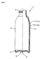
- Fig. 1 is a front view, partially shown in a vertical section, of the double container.
- This double container is molded by a direct blow molding process, and is a bottle having a neck 2, a cylindrical body 3, and a bottom 4.
- This double container 1 comprises an outer container 11a made from an outer layer 11 of a polyethylene terephthalate (PET) resin and an inner container 12a made from an inner layer 12 of a polypropylene (PP) resin.
- PET polyethylene terephthalate
- PP polypropylene
- the process for molding the double container 1 of Fig. 1 is described below. First, mutually non-adherent outer and inner layers are laminated by a multi-layer extrusion molding process to form a multi-layered parison. Then, the double container 1 can be molded by blow molding this multi-layered parison in a molten state, according to the direct blow molding process.
- Fig. 3 is a front view, partially shown in a vertical section, of a pump-fitted container 40 obtained by using the double container 1a.
- the pump-fitted container 40 comprises a double container 1a and a pump P of a manually depressed type fitted firmly to the neck 2.
- the container 1a has construction similar to the double container of the first embodiment, but has a relatively thin inner layer 12, and this inner layer 12 forms an inner container 12a which is deformable in an inwardly deflating manner with the drop of inner pressure.
- the container 1a performs the function as a delaminatable bottle.
- the container 1a is a double container having the space 13 formed between the outer layer 11 and the inner layer 12 due to the mold shrinkage, and this space 13 starts from the cracked pinch off portion 6 in the bottom portion of the outer layer 11.
- the molded double container is capable of eliminating the steps of putting the inner container 12a under reduced pressure to deform the inner container 12a and to peel the inner layer 12 from the outer layer and then allowing the inner container 12a to restore the original shape again.
- the pump P is pushed down under the condition that the inner container 12a has been filled with the contents, then the contents are discharged from a front nozzle by way of a discharge passage.
- the inner container 12a is deformable in a deflating manner to an extent to which the contents have been dispensed (See a two-dot chain line in Fig. 3 ).
- the pump P is released from the pressed condition. At that time, outside air is taken into the space between the outer layer 11 and the inner layer 12 in an amount corresponding to the extent to which the inner container 12a has been deflated.
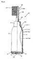
- Fig. 4 is a front view, partially shown in a vertical section, of a comb-fitted container 20 having a comb attachment 25 fitted to the upper end of the container 1a.
- This container 1a has the construction roughly similar to the double container of the first embodiment.
- the inner container 12a is formed by a relatively thin inner layer 12 and is deformable in an inwardly deflating manner with the drop of inner pressure.
- This double container has the function as a delaminatable bottle of the squeezable type.
- a cap 21 is tightly fitted around the neck 2 of the container 1a by utilizing an O-ring 23.
- the comb attachment 25 is fitted firmly to the container by way of this cap 21.
- a first check valve 22 is disposed on a flat roof of the cap 21.
- a cylindrical base cup 31 having a bottom of its own is tightly fitted around the container bottom 5.
- a second check valve 32 is disposed on the bottom plate of this base cup 31.
- the bottle If the bottle is squeezed with a hand under the condition that the inner container 12a has been filled with the contents, there opens the first check valve 22.
- the contents go up the discharge flow passage 26 of the comb attachment 25, and are discharged through discharge ports 26a into a space among teeth.
- the inner container 12a is deformed in a deflating manner to an extent to which the contents have been dispensed (See a two-dot chain line in Fig. 4 ).
- the container After an amount of the contents has been discharged, the container is released from the squeeze.
- the outer container 11a made of the outer layer 11 returns to its former shape due to the elastic restoring force.
- the second check valve 32 opens, and outside air is taken into the space between the outer layer 11 and the inner layer 12 in an amount corresponding to the extent to which the inner container 12a has been deflated.
- the second check valve 32 returns to the closed position. At that time, the sealing function of the base cup 31 is activated to confine the air within the space between the outer layer 11 and the inner layer 12. Therefore, the squeezing movements can be repeated easily.
- the comb-attached container 20 in the third embodiment comprises that the bottom 4 is provided with a means of taking in air through the cracked pinch-off portion 6 and is sealed with the base cup 31 having the second check valve 32.
- the bottom seal 5 may be of a non-cracked type such as shown in Fig. 2 . In that case, an air intake hole is formed in the outer layer 11 of the neck 2 to let the air in the space between the outer layer 11 and the inner layer 12.
- the second check valve is disposed on a peripheral wall of the cap 21 to stop air flow through this air intake hole.
- another layer or other layers can be laminated on the outer surface of the outer layer and/or on the inner surface of the inner layer.
- the synthetic resins can be variously combined for the outer and inner layers, taking the mold shrinkage and the adherent strength of both layers into account.
- a PET resin and a PP resin there are also other usable combinations, including such combinations as PP/PE (polyethylene), PET/PE, and PEN (polyethylene naphthalate)/PE.
- the mold shrinkage and adherent strength of both layers can be controlled by blending a main component with another synthetic resin or by dispersing a pigment or filler in the main component.
Landscapes
- Engineering & Computer Science (AREA)
- Mechanical Engineering (AREA)
- Manufacturing & Machinery (AREA)
- Ceramic Engineering (AREA)
- Containers Having Bodies Formed In One Piece (AREA)
- Blow-Moulding Or Thermoforming Of Plastics Or The Like (AREA)
- Packages (AREA)
- Details Of Rigid Or Semi-Rigid Containers (AREA)
Description
- This invention relates to process for forming a synthetic resin double container having a space formed between an outer layer and an inner layer, wherein the container is formed by direct blow molding.
-
Patent Document 1 describes an invention of a double container comprising a cylindrical outer container and an inner container wherein upper portions of the outer and inner container are fixed each other with a fitting cap. Such double containers are in use as a heat insulating container utilizing the double walls, or in the field of cosmetics containers, as a decorative container having a transparent outer container in which an inner container looks afloat. - [Patent Document 1] Published patent application
JP2004-352327 - The double container described in
Patent Document 1 is formed by inserting the inner container into the outer container and fitting the cap around the outer container in an undercut engagement. Because of the need to insert the inner container into the outer container, the neck is required to have a large bore diameter, and this is a limitation from the aspect of its shape. Furthermore, there is a problem of additional positions, parts, or steps for assembling the outer and inner containers. -
US 6 083 450 A discloses a multilayer container including an outer relatively rigid plastic layer having a body portion, a finish defining an opening and a base having an atmospheric vent opening therethrough. The container includes an inner flexible plastic layer of relatively thin flexible material throughout which does not adhere to the outer plastic layer. The method of making the multilayer container includes coextruding a parison comprising the relatively thick outer layer of plastic material and the relatively thin inner layer of plastic material. -
DE 84 33 745 U1 discloses a process for the production of a packaging having a closable opening and an outer container which is substantially stiff as to its shape and within which a container of flexible material is disposed. The parison can be provided with an air gap between outer and inner layer. -
EP 0 756 928 A1 discloses a separable multi-layer plastic container having an outer layer and an inner layer, wherein a slit is provided in a neck portion for introducing atmospheric air between the inner layer and the outer layer. -
EP 0 893 356A discloses a container formed from at least two layers including an outer layer and an inner layer which are coextruded and do not adhere to each other, the inner layer being collapsible, the outer layer being porous. - This invention has been made to solve the problems associated with double container. The technical problem of this invention is thus to create a synthetic resin double container that can be molded in simple steps without any limitation from the aspect of shape.
- A principal means of this invention to solve the above technical problem comprises a double container made by a direct blow molding process wherein a space is formed between the outer layer and the inner layer made of synthetic resins that are mutually non-adherent, thus allowing both layers to be left in a detached state due to a difference in mold shrinkage factors between the two layers revealed in a direct blow molding step.
- The inventors of this application molded a multi-layered parison having an outer layer and an inner layer laminated to each other by a multi-layer extrusion molding process, and studied a direct blow molding process for direct blow molding the multi-layered parison in the molten state. They have found that a space is formed by combining synthetic resins to be used as the outer and inner layers so that the two layers would be peeled from each other due to mold shrinkage after the container has been released from the mold. This finding has led them to make this invention.
- The double container having the space between the outer and inner layers can be molded by utilizing the difference in mold shrinkage factors of the outer and inner layers in an ordinary direct blow molding process, without requiring any additional steps of inserting the inner container into the outer container and firmly fitting the former to the latter.
- A basic requirement for the outer layer and the inner layer to be peeled from each other due to the mold shrinkage occurring in the direct blow molding process is that the inner layer has a larger mold shrinkage factor than the outer layer has. On the other hand, both layers are in a closely attached condition right after the blow molding even though both layers are non-adherent to each other. Therefore, another principal requirement for both layers to be peeled from each other is that the closely attached outer and inner layers have low adherent strength.
- Due to the difference in the mold shrinkage factors, the peeling force acts on the interface between the outer layer and the inner layer. The synthetic resins used respectively in the outer and inner layers and the blow molding conditions are selected so that this peeling force becomes larger than the adherent strength of both layers. In this way, a space can be formed effectively between the outer layer and the inner layer, due to the mold shrinkage involved in the direct blow molding.
- Furthermore, the synthetic resin selected for the outer layer or the inner layer is not only used independently as the main component, but also can be blended with, e.g., an elastomer, or the main component may have a pigment, a filler, etc., dispersed therein. The blends with, or dispersion of, other components can also be of help in increasing the mold shrinkage for the inner layer and decreasing the strength of close contact between the outer and inner layers, thus making it possible to proceed with the separation of both layers smoothly. The inner layer may also comprise two adhesively laminated layers having different mold shrinkage factors. In this case, the inner layer can be deformed flexibly in a bimetallic manner so as to be peeled from the outer layer.
- From the aspect of molding conditions, a large difference in the mold shrinkage factors between both layers can be obtained by a parison molding temperature or a blow air temperature that gives differences in the cooling speed or in the behavior of expansion in the blow molding of the outer and inner layers.
- If the double wall is utilized as a means of heat insulation, it is preferred that the space between outer and inner layers is formed over an almost entire area of the container except for the neck. Or both layers can be partially peeled for any purpose. For instance, the container can be decorated with both of peeled portions and closely contacted portions according to a certain pattern.
- In the case of a bottle-like container having a neck, this neck of the bottle remains in the same shape as the preform neck since the neck undergoes little deformation during the blow molding. The outer and inner layers can be fitted to each other firmly at this neck.
- In addition to the above basic construction, an outer layer portion of a bottom seal has a cracked pinch-off portion in a bottom, wherein the bottom seal is formed in an underside surface of a bottom by a pinch-off section of a split blow mold, and wherein the cracked pinch-off portion in the bottom is formed by the action of mold shrinkage involved in the direct blow molding process.
- The bottom seal is a portion where large pressing force is applied by the mold pinch-off section. Therefore, the bottom seal has large residual strain, and tends to deform due to mold shrinkage involved in the direct blow molding. Since the outer and inner layers are non-adherent to each other, the cracked pinch-off portion can be easily formed in the outer layer portion as it is peeled partially from the inner layer.
- The formation of the cracked pinch-off portion takes place roughly at the same time with the development of the peeling force that acts on the interface between the outer layer and the inner layer as a result of mold shrinkage. Peeling starts from the cracked pinch-off portion, and the separation of the outer layer from the inner layer propagates smoothly all over the container, and the space between both layers can be formed easily, thus allowing the cracked pinch-off portion to serve as an air intake port to let the air in this space.
- The above construction is concerned with a peelably laminated container or a so-called delaminatable container, in which the inner container is formed by the inner layer made of a flexible synthetic resin and molded to have a thin wall. When the contents are discharged under this construction, the inner layer peels from the outer layer, and the inner container deflates and falls in a decompressed state. Even if the remaining amount gets low, the contents can be discharged smoothly.
- The delaminatable container is molded by first molding a laminated parison by a multi-layer extrusion molding process and then blow molding the laminated parison. Under the blow molded condition, the outer and inner layers are laminated in an adherent state. Before the container is filled with contents, the inner layer is usually suctioned from inside by means of some vacuum equipment to put the inside of the inner container reduced pressure, so that the inner layer is peeled from the outer layer over a roughly entire area of the container. Then, before the container is used, pressurized air is applied to the inner container to let the inner container restore the shape resembling that of the outer container made of the outer layer.
- Thus, under the above construction, a space is formed between the outer and inner layers due to the mold shrinkage involved in the direct blow molding process. Therefore, this invention eliminates the above-described additional steps of peeling the inner layer from the outer layer.
- This invention has the following effects:
The double container having a space between the outer layer and the inner layer, which constitutes the main construction of this invention, has no need of inserting the inner container into the outer container and fixing the outer container and the inner container each other. The double container of this invention can be molded easily by utilizing the difference in mold shrinkage factors between the outer layer and the inner layer in an ordinary direct blow molding process. - The container has a cracked pinch-off portion in the outer layer portion of the bottom seal, the cracked pinch-off portion is formed roughly at the same time with the development of the peeling force that acts on the interface between the outer layer and the inner layer as a result of mold shrinkage. Peeling starts from the cracked pinch-off portion, and the separation of the inner layer from the outer layer propagates smoothly all over the container, and the space between both layers can be formed easily.
- In the case of a container in which the inner layer forms an inner container which is deformable in a deflating manner inwardly with the drop of inner pressure, this invention is concerned with a so-called delaminatable container. Since the space is formed by peeling the inner layer from the outer layer due to the mold shrinkage involved in the direct blow molding process, this invention eliminates the additional step of separating the inner layer tentatively from the outer layer, which has been required in the production of conventional delaminatable containers.
-
-
Fig. 1 is a front view, partially shown in a vertical section, of the double container. -
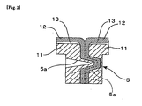
Fig. 2 is a vertical section showing another example of the bottom seal. -
Fig. 3 is a front view, partially shown in a vertical section, of a pump-fitted container obtained by using the double container. -
Fig. 4 is a front view, partially shown in a vertical section, of a comb-fitted container obtained by using the double container. -
- 1. Double container
- 1a. Container
- 2. Neck
- 3. Body
- 4. Bottom
- 5. Bottom seal
- 5a. Pin-driven cavity
- 6. Cracked pinch-off portion
- 11. Outer layer
- 11a. Outer container
- 12. Inner layer
- 12a. Inner container
- 13. Space
- 20. Container with a comb attachment
- 21. Cap
- 22. First check valve
- 23. O-ring
- 25. Comb attachment
- 26. Discharge flow passage
- 26a. Discharge port
- 27. Tooth
- 31. Base cup
- 32. Second check valve
- P. Pump
- .
Fig. 1 is a front view, partially shown in a vertical section, of the double container. This double container is molded by a direct blow molding process, and is a bottle having aneck 2, acylindrical body 3, and abottom 4. - This
double container 1 comprises anouter container 11a made from anouter layer 11 of a polyethylene terephthalate (PET) resin and aninner container 12a made from aninner layer 12 of a polypropylene (PP) resin. Aspace 13 is formed between theouter layer 11 and theinner layer 12 over an area ranging from right under theneck 2 to thebottom 5, and thus, thedouble container 1 has a double-wall structure in which thespace 13 is sandwiched between both layers. - The process for molding the
double container 1 ofFig. 1 is described below. First, mutually non-adherent outer and inner layers are laminated by a multi-layer extrusion molding process to form a multi-layered parison. Then, thedouble container 1 can be molded by blow molding this multi-layered parison in a molten state, according to the direct blow molding process. - As soon as the blow molded product is released from the mold, the overall mold shrinkage of the product begins and goes on. A
bottom seal 5 in thebottom 4 is formed when the parison is pressed and cut by a great deal of power of the mold pinch-off section. Therefore, thebottom seal 5 has especially large residual strain. In addition, since thebottom seal 5 is a relatively thick wall portion, theouter layer 11 is partially peeled from theinner layer 12 with the progress of the mold shrinkage, as shown inFig. 1 . A cracked pinch-off portion 6 is thus formed in the bottom portion of theouter layer 11. - In the meantime, if an
outer layer 11 made of a PET resin and aninner layer 12 made of a PP resin are used as in this embodiment so that theinner layer 12 has a larger mold shrinkage factor than theouter layer 11 has, then with the progress of mold shrinkage, the peeling force to separate layers acts on the interface between theouter layer 11 and theinner layer 12. Starting from the cracked pinch-off portion 6, where theouter layer 11 and theinner layer 12 have been partially peeled from each other, and taking in outside air through the cracked pinch-off portion 6, the separation of layers propagates all over the container due to the action of this peeling force. As shown inFig. 1 , thespace 13 is formed in portions other than theneck 2, and the double-wall structure is completed with thespace 13 being sandwiched by the outer and inner layers. - The separation of layers does not occur at the
neck 2, and both the outer and inner layers remain adherent after the mold shrinkage has taken place, because theneck 2 does not deform largely at the time of blow molding. -
Fig. 3 is a front view, partially shown in a vertical section, of a pump-fittedcontainer 40 obtained by using thedouble container 1a. The pump-fittedcontainer 40 comprises adouble container 1a and a pump P of a manually depressed type fitted firmly to theneck 2. Thecontainer 1a has construction similar to the double container of the first embodiment, but has a relatively thininner layer 12, and thisinner layer 12 forms aninner container 12a which is deformable in an inwardly deflating manner with the drop of inner pressure. Thus, thecontainer 1a performs the function as a delaminatable bottle. - The
container 1a is a double container having thespace 13 formed between theouter layer 11 and theinner layer 12 due to the mold shrinkage, and thisspace 13 starts from the cracked pinch offportion 6 in the bottom portion of theouter layer 11. Unlike conventional delaminatable bottles, the molded double container is capable of eliminating the steps of putting theinner container 12a under reduced pressure to deform theinner container 12a and to peel theinner layer 12 from the outer layer and then allowing theinner container 12a to restore the original shape again. - If the pump P is pushed down under the condition that the
inner container 12a has been filled with the contents, then the contents are discharged from a front nozzle by way of a discharge passage. Theinner container 12a is deformable in a deflating manner to an extent to which the contents have been dispensed (See a two-dot chain line inFig. 3 ). After an amount of the contents has been discharged, the pump P is released from the pressed condition. At that time, outside air is taken into the space between theouter layer 11 and theinner layer 12 in an amount corresponding to the extent to which theinner container 12a has been deflated. -
Fig. 4 is a front view, partially shown in a vertical section, of a comb-fittedcontainer 20 having acomb attachment 25 fitted to the upper end of thecontainer 1a. Thiscontainer 1a has the construction roughly similar to the double container of the first embodiment. Theinner container 12a is formed by a relatively thininner layer 12 and is deformable in an inwardly deflating manner with the drop of inner pressure. This double container has the function as a delaminatable bottle of the squeezable type. - A
cap 21 is tightly fitted around theneck 2 of thecontainer 1a by utilizing an O-ring 23. Thecomb attachment 25 is fitted firmly to the container by way of thiscap 21. Afirst check valve 22 is disposed on a flat roof of thecap 21. - Meanwhile, a
cylindrical base cup 31 having a bottom of its own is tightly fitted around thecontainer bottom 5. Asecond check valve 32 is disposed on the bottom plate of thisbase cup 31. - If the bottle is squeezed with a hand under the condition that the
inner container 12a has been filled with the contents, there opens thefirst check valve 22. The contents go up thedischarge flow passage 26 of thecomb attachment 25, and are discharged throughdischarge ports 26a into a space among teeth. Theinner container 12a is deformed in a deflating manner to an extent to which the contents have been dispensed (See a two-dot chain line inFig. 4 ). - After an amount of the contents has been discharged, the container is released from the squeeze. The
outer container 11a made of theouter layer 11 returns to its former shape due to the elastic restoring force. At that time, thesecond check valve 32 opens, and outside air is taken into the space between theouter layer 11 and theinner layer 12 in an amount corresponding to the extent to which theinner container 12a has been deflated. - When the
body 3 is squeezed again to discharge the contents, thesecond check valve 32 returns to the closed position. At that time, the sealing function of thebase cup 31 is activated to confine the air within the space between theouter layer 11 and theinner layer 12. Therefore, the squeezing movements can be repeated easily. - The comb-attached
container 20 in the third embodiment comprises that thebottom 4 is provided with a means of taking in air through the cracked pinch-off portion 6 and is sealed with thebase cup 31 having thesecond check valve 32. However, under different construction, thebottom seal 5 may be of a non-cracked type such as shown inFig. 2 . In that case, an air intake hole is formed in theouter layer 11 of theneck 2 to let the air in the space between theouter layer 11 and theinner layer 12. The second check valve is disposed on a peripheral wall of thecap 21 to stop air flow through this air intake hole. - If necessary, another layer or other layers can be laminated on the outer surface of the outer layer and/or on the inner surface of the inner layer. The synthetic resins can be variously combined for the outer and inner layers, taking the mold shrinkage and the adherent strength of both layers into account. In addition to the combination of a PET resin and a PP resin, there are also other usable combinations, including such combinations as PP/PE (polyethylene), PET/PE, and PEN (polyethylene naphthalate)/PE. The mold shrinkage and adherent strength of both layers can be controlled by blending a main component with another synthetic resin or by dispersing a pigment or filler in the main component.
Claims (1)
- A process for forming a synthetic resin double container having a space (13) formed between an outer layer (11) and an inner layer (12), wherein
the bottle is formed by direct blow molding.
the inner layer (12) is made of a synthetic resin having a larger mold shrinkage factor than the outer layer (11) has and wherein
outer and inner layers (11, 12) are mutually adhered during the blow molding process, and wherein
a bottom seal (5) is formed on an underside surface of a bottom by a pinch-off section (6) of a split blow mold, where a portion of the outer layer (11) in the bottom seal (5) has a cracked pinch-off portion (6) formed by mold shrinking involved in the direct blow molding process, wherein
peeling with a peeling force being larger than the adherent strength of both layers (11, 12), of the low _adhered inner and outer layer starts from the cracked pinch-off portion (6) by taking in outside air through the cracked pinch-off portion, and
the separation of the inner layer (12) from the outer layer (11) propagates smoothly all over the container, leaving both the outer, and inner layers to be in a detached, non-adhered state.
Applications Claiming Priority (2)
| Application Number | Priority Date | Filing Date | Title |
|---|---|---|---|
| JP2007172672A JP5267901B2 (en) | 2007-06-29 | 2007-06-29 | Synthetic resin double container by direct blow molding method |
| PCT/JP2008/061189 WO2009004927A1 (en) | 2007-06-29 | 2008-06-19 | Double container of synthetic resin by direct blow molding method |
Publications (3)
| Publication Number | Publication Date |
|---|---|
| EP2172400A1 EP2172400A1 (en) | 2010-04-07 |
| EP2172400A4 EP2172400A4 (en) | 2010-07-14 |
| EP2172400B1 true EP2172400B1 (en) | 2013-08-28 |
Family
ID=40225978
Family Applications (1)
| Application Number | Title | Priority Date | Filing Date |
|---|---|---|---|
| EP08765744.1A Not-in-force EP2172400B1 (en) | 2007-06-29 | 2008-06-19 | A direct blow molding process for forming a double container of synthetic resin |
Country Status (8)
| Country | Link |
|---|---|
| US (1) | US9067709B2 (en) |
| EP (1) | EP2172400B1 (en) |
| JP (1) | JP5267901B2 (en) |
| KR (1) | KR101493534B1 (en) |
| CN (1) | CN101547836B (en) |
| AU (1) | AU2008272244B2 (en) |
| CA (1) | CA2692461C (en) |
| WO (1) | WO2009004927A1 (en) |
Families Citing this family (43)
| Publication number | Priority date | Publication date | Assignee | Title |
|---|---|---|---|---|
| JP5267901B2 (en) | 2007-06-29 | 2013-08-21 | 株式会社吉野工業所 | Synthetic resin double container by direct blow molding method |
| KR200454300Y1 (en) * | 2009-03-16 | 2011-06-27 | (주)영진팩 | Brow Multi Molding Container |
| EP2669214B1 (en) | 2009-07-09 | 2016-01-20 | Advanced Technology Materials, Inc. | Storage system with a blow molded collapsible liner |
| TW201242670A (en) | 2010-11-23 | 2012-11-01 | Advanced Tech Materials | Liner-based dispenser |
| EP2681124A4 (en) | 2011-03-01 | 2015-05-27 | Advanced Tech Materials | EXTERNAL ENVELOPE AND INTERNAL BLOW MOLDED INTERNAL TRIM AND METHODS OF MANUFACTURING SAME |
| KR101673830B1 (en) * | 2012-10-31 | 2016-11-07 | 가부시키가이샤 요시노 고교쇼 | Double container |
| JP6011929B2 (en) * | 2012-10-31 | 2016-10-25 | 株式会社吉野工業所 | Biaxial stretch blow molded container and manufacturing method thereof |
| JP6345062B2 (en) * | 2013-09-30 | 2018-06-20 | 株式会社吉野工業所 | Delamination container |
| CN105793162B (en) * | 2013-11-27 | 2019-07-02 | 京洛株式会社 | Laminated peel container and method for producing the same |
| MX370105B (en) * | 2014-02-06 | 2019-12-02 | Alpla Werke Alwin Lehner Gmbh & Co Kg | Plastic container produced in an extrusion blow molding method, in particular plastic bottle. |
| JP6421458B2 (en) * | 2014-05-29 | 2018-11-14 | キョーラク株式会社 | Delamination container |
| JP6407649B2 (en) * | 2014-09-30 | 2018-10-17 | 株式会社吉野工業所 | Delamination container |
| AU2015329264B2 (en) * | 2014-10-07 | 2018-08-30 | Kyoraku Co., Ltd. | Delaminated container manufacturing method and air leak inspection method for delaminated container |
| KR101655989B1 (en) * | 2014-10-20 | 2016-09-09 | (주)아모레퍼시픽 | Pump container for preventing the rest having a body with double structure |
| JP2016097978A (en) * | 2014-11-18 | 2016-05-30 | 株式会社平和化学工業所 | Double container for high viscous liquid |
| KR101611211B1 (en) * | 2015-04-24 | 2016-04-26 | 허재영 | The whole quantity consumption type tools |
| KR200481312Y1 (en) * | 2015-07-14 | 2016-09-09 | 마루니 코리아 주식회사 | Plastic dual container |
| TW201716297A (en) * | 2015-11-06 | 2017-05-16 | Well Max Beauty Lab Co Ltd | Dual-layered container and production method thereof can prevent the container from generating negative pressure through intake of the air gap and shrinkage deformation of the separation portion |
| CN105398637A (en) * | 2015-12-03 | 2016-03-16 | 中山汇伟塑胶工业有限公司 | Plastic bottle body with high structural strength |
| JP6737590B2 (en) * | 2015-12-09 | 2020-08-12 | 株式会社平和化学工業所 | Double container and manufacturing method thereof |
| JP6594771B2 (en) * | 2015-12-25 | 2019-10-23 | 株式会社吉野工業所 | Double container |
| ES2901614T3 (en) * | 2016-06-17 | 2022-03-23 | Dainippon Printing Co Ltd | Composite preform, process for manufacturing the same, composite container, process for manufacturing said composite container and heat-shrinkable plastic member |
| ES2762865T3 (en) * | 2016-09-26 | 2020-05-26 | Boehringer Ingelheim Int | Procedure to test the tightness of a bag in the interior of a container |
| JP6959498B2 (en) * | 2017-01-26 | 2021-11-02 | キョーラク株式会社 | Laminate peeling container |
| CN110382371A (en) * | 2017-03-15 | 2019-10-25 | 京洛株式会社 | Laminated peeling container |
| JP7497975B2 (en) * | 2017-04-05 | 2024-06-11 | キッコーマン株式会社 | Discharge Container |
| US11388986B2 (en) | 2018-05-04 | 2022-07-19 | Maxro Llc | Liquid dispensing hairbrush systems and associated devices |
| WO2020262595A1 (en) | 2019-06-28 | 2020-12-30 | 日精エー・エス・ビー機械株式会社 | Apparatus for producing resin molded article, method for producing resin molded article, and resin molded article |
| EP4674774A3 (en) | 2019-09-26 | 2026-04-01 | Nissei ASB Machine Co., Ltd. | Method for producing delamination container and apparatus for producing delamination container |
| CN113272233A (en) * | 2019-11-22 | 2021-08-17 | 深圳市德昌裕塑胶制品有限公司 | Flexible pipe container formed by multi-layer co-extrusion once |
| JP7422865B2 (en) | 2020-04-06 | 2024-01-26 | 日精エー・エス・ビー機械株式会社 | Hot runner type and resin container manufacturing equipment |
| US20230150710A1 (en) * | 2020-04-06 | 2023-05-18 | Nissei Asb Machine Co., Ltd. | Peeling container and method for manufacturing peeling container |
| JP7353471B2 (en) | 2020-04-06 | 2023-09-29 | 日精エー・エス・ビー機械株式会社 | Manufacturing method and manufacturing device for peelable containers |
| CN120941701A (en) * | 2020-04-06 | 2025-11-14 | 日精Asb机械株式会社 | Method and apparatus for manufacturing a stripping container |
| EP4190528A4 (en) | 2020-08-03 | 2024-09-18 | Nissei ASB Machine Co., Ltd. | METHOD FOR MANUFACTURING RESIN CONTAINER, DIE UNIT AND BLOW MOLDING DEVICE |
| CN112263476B (en) * | 2020-10-14 | 2024-09-20 | 台州市祥珑食品容器科技股份有限公司 | Container and method for manufacturing the same |
| CN112674578B (en) * | 2020-12-06 | 2022-08-26 | 东莞合发包装制品有限公司 | Blow molding equipment and blow molding method |
| DE102021116278B4 (en) * | 2021-06-23 | 2024-02-29 | Gaplast Gmbh | Method and device for producing a container consisting of a rigid outer container and an easily deformable inner bag |
| IT202100017447A1 (en) * | 2021-07-02 | 2023-01-02 | Lumson Spa | Method of making a container for a dispensing device for a fluid substance, and dispensing device for that fluid substance |
| TWI777789B (en) * | 2021-09-27 | 2022-09-11 | 宏全國際股份有限公司 | Double-Wall Tubes, Double-Wall Containers, and Pneumatic Backstop Lid |
| TWI777788B (en) * | 2021-09-27 | 2022-09-11 | 宏全國際股份有限公司 | Double embryo, double bottle and air-operated backstop |
| CN115891107A (en) * | 2021-12-16 | 2023-04-04 | 常熟市沈氏塑业有限公司 | A double-layer bottle and blow molding method thereof |
| CN115256873A (en) * | 2022-08-17 | 2022-11-01 | 深圳润芳包装科技有限公司 | Disposable blow molding double-layer vacuum blowing bottle and manufacturing method thereof |
Family Cites Families (28)
| Publication number | Priority date | Publication date | Assignee | Title |
|---|---|---|---|---|
| US4071597A (en) * | 1974-09-13 | 1978-01-31 | Owens-Illinois, Inc. | Container with improved heat-shrunk cellular sleeve |
| US4261473A (en) * | 1975-12-17 | 1981-04-14 | Toyo Seikan Kaisha Limited | Molded container having wall composed of oriented resin blend |
| US4182457A (en) * | 1976-08-10 | 1980-01-08 | Toyo Seikan Kaisha Limited | Multilayer container |
| JPS57151314A (en) * | 1981-03-17 | 1982-09-18 | Yoshino Kogyosho Co Ltd | Synthetic resin made bottle and method for molding the same |
| CA1191006A (en) * | 1982-01-14 | 1985-07-30 | Sekisui Kaseihin Kogyo Kabushiki Kaisha | Sheet for forming sleeve and process for producing the same |
| DE8433745U1 (en) * | 1984-11-17 | 1985-03-28 | Kautex Werke Reinold Hagen AG, 5300 Bonn | With a sealable opening provided packaging |
| US4816305A (en) * | 1987-05-20 | 1989-03-28 | Mcneilab Inc. | Multi-walled tamper-proof container and method for enhancing tamper evidence |
| JPH0613099Y2 (en) * | 1988-02-18 | 1994-04-06 | キョーラク株式会社 | Squeeze container |
| JPH0748519Y2 (en) * | 1989-12-25 | 1995-11-08 | 大成化工株式会社 | Double container |
| JP2586294B2 (en) * | 1993-06-14 | 1997-02-26 | 東洋製罐株式会社 | Laminated release bottle and method for producing the same |
| JP3401519B2 (en) * | 1995-02-16 | 2003-04-28 | 株式会社吉野工業所 | Blow molding container and mold for molding the same |
| JPH09286084A (en) * | 1996-04-22 | 1997-11-04 | Tonen Chem Corp | Polythylenic resin laminate and large-scale clean container formed therefrom |
| WO1997045245A1 (en) * | 1996-05-30 | 1997-12-04 | Yoshino Kogyosho Co., Ltd. | Extrusion blow molded container having cylindrical drum portion and mold for shaping the container |
| CA2230768C (en) * | 1997-02-28 | 2007-02-13 | John W. Safian | Multilayer container package |
| DE19719252C2 (en) * | 1997-05-07 | 2002-10-31 | Valeo Klimatech Gmbh & Co Kg | Double-flow and single-row brazed flat tube evaporator for a motor vehicle air conditioning system |
| US6413600B1 (en) * | 1997-05-22 | 2002-07-02 | Plastipak Packaging, Inc. | Multi-layer container and preform and process for obtaining same |
| EP0893356A1 (en) * | 1997-07-23 | 1999-01-27 | The Procter & Gamble Company | Multilayer pressure resistant container |
| US6749780B2 (en) * | 2000-06-27 | 2004-06-15 | Graham Packaging Company, L.P. | Preform and method for manufacturing a multi-layer blown finish container |
| JP3817600B2 (en) * | 2000-07-31 | 2006-09-06 | 株式会社吉野工業所 | Synthetic resin housing |
| US6461699B1 (en) * | 2000-10-06 | 2002-10-08 | Plastipak Packaging, Inc. | Plastic container having a carbon-treated internal surface for non-carbonated food products |
| CN1332856C (en) * | 2001-10-31 | 2007-08-22 | 株式会社吉野工业所 | Blow-molded container |
| US6719173B2 (en) * | 2002-03-25 | 2004-04-13 | Owens-Brockway Plastic Products Inc. | Multilayer container package for dispensing a liquid product |
| EP1500603B1 (en) * | 2002-04-30 | 2011-06-08 | Yoshino Kogyosho Co., Ltd. | Pouring container |
| JP4107585B2 (en) | 2003-05-30 | 2008-06-25 | 株式会社吉野工業所 | Replacement type double container |
| JP4416081B2 (en) * | 2004-01-30 | 2010-02-17 | ホーユー株式会社 | Delami bottle |
| FR2866321B1 (en) * | 2004-02-13 | 2007-05-18 | Lablabo | DEFORMABLE SOFT POUCH AND DEVICE FOR PACKAGING AND DISPENSING FLUID PRODUCTS. |
| JP4535259B2 (en) * | 2004-09-30 | 2010-09-01 | 株式会社吉野工業所 | Blow molding container |
| JP5267901B2 (en) | 2007-06-29 | 2013-08-21 | 株式会社吉野工業所 | Synthetic resin double container by direct blow molding method |
-
2007
- 2007-06-29 JP JP2007172672A patent/JP5267901B2/en active Active
-
2008
- 2008-06-19 CN CN2008800007747A patent/CN101547836B/en active Active
- 2008-06-19 US US12/452,272 patent/US9067709B2/en active Active
- 2008-06-19 AU AU2008272244A patent/AU2008272244B2/en not_active Ceased
- 2008-06-19 WO PCT/JP2008/061189 patent/WO2009004927A1/en not_active Ceased
- 2008-06-19 EP EP08765744.1A patent/EP2172400B1/en not_active Not-in-force
- 2008-06-19 KR KR1020097006902A patent/KR101493534B1/en not_active Expired - Fee Related
- 2008-06-19 CA CA2692461A patent/CA2692461C/en active Active
Also Published As
| Publication number | Publication date |
|---|---|
| JP5267901B2 (en) | 2013-08-21 |
| AU2008272244B2 (en) | 2013-06-20 |
| US20100200586A1 (en) | 2010-08-12 |
| EP2172400A4 (en) | 2010-07-14 |
| AU2008272244A1 (en) | 2009-01-08 |
| KR101493534B1 (en) | 2015-02-13 |
| CN101547836A (en) | 2009-09-30 |
| KR20100027088A (en) | 2010-03-10 |
| WO2009004927A1 (en) | 2009-01-08 |
| CN101547836B (en) | 2013-07-31 |
| CA2692461C (en) | 2015-11-10 |
| US9067709B2 (en) | 2015-06-30 |
| EP2172400A1 (en) | 2010-04-07 |
| CA2692461A1 (en) | 2009-01-08 |
| JP2009007060A (en) | 2009-01-15 |
Similar Documents
| Publication | Publication Date | Title |
|---|---|---|
| US9067709B2 (en) | Synthetic resin double container molded by direct blow molding process | |
| EP3257652B1 (en) | A process for producing a biaxially stretch blow-molded container | |
| CA2433407C (en) | Blow-molded container | |
| JP2004231280A (en) | Synthetic resin container | |
| EP3202678B1 (en) | Delamination container | |
| WO1996025284A1 (en) | Blown container and blow mold | |
| JP3745897B2 (en) | Laminated preform and molding method thereof | |
| WO2019146224A1 (en) | Delamination container | |
| JP7566420B2 (en) | Layered container | |
| JP2008189376A (en) | Inner layer-peelable type dispenser vessel | |
| JP2004231270A (en) | Synthetic resin container | |
| JP3556344B2 (en) | Laminated blow container | |
| JP7058919B2 (en) | Double container cap | |
| JPH11292076A (en) | Laminate container whose inner layer is peelable, and molding method thereof | |
| JP7570785B2 (en) | Layered container | |
| JP7669098B2 (en) | Layered container | |
| JP7391480B2 (en) | laminated peel container | |
| SE519704C2 (en) | Packaging and method of preparation thereof | |
| JP2025152022A (en) | double container | |
| JP6746206B2 (en) | Double container | |
| JP3864433B2 (en) | Method for preventing inner layer falling in delamination container and member therefor | |
| JP2024053924A (en) | Composite containers, composite containers with lids, and composite preforms | |
| JPH11268721A (en) | Delamination bottle |
Legal Events
| Date | Code | Title | Description |
|---|---|---|---|
| PUAI | Public reference made under article 153(3) epc to a published international application that has entered the european phase |
Free format text: ORIGINAL CODE: 0009012 |
|
| 17P | Request for examination filed |
Effective date: 20100118 |
|
| AK | Designated contracting states |
Kind code of ref document: A1 Designated state(s): AT BE BG CH CY CZ DE DK EE ES FI FR GB GR HR HU IE IS IT LI LT LU LV MC MT NL NO PL PT RO SE SI SK TR |
|
| AX | Request for extension of the european patent |
Extension state: AL BA MK RS |
|
| A4 | Supplementary search report drawn up and despatched |
Effective date: 20100611 |
|
| DAX | Request for extension of the european patent (deleted) | ||
| 17Q | First examination report despatched |
Effective date: 20110506 |
|
| GRAP | Despatch of communication of intention to grant a patent |
Free format text: ORIGINAL CODE: EPIDOSNIGR1 |
|
| GRAS | Grant fee paid |
Free format text: ORIGINAL CODE: EPIDOSNIGR3 |
|
| GRAP | Despatch of communication of intention to grant a patent |
Free format text: ORIGINAL CODE: EPIDOSNIGR1 |
|
| GRAP | Despatch of communication of intention to grant a patent |
Free format text: ORIGINAL CODE: EPIDOSNIGR1 |
|
| GRAA | (expected) grant |
Free format text: ORIGINAL CODE: 0009210 |
|
| INTG | Intention to grant announced |
Effective date: 20130712 |
|
| AK | Designated contracting states |
Kind code of ref document: B1 Designated state(s): AT BE BG CH CY CZ DE DK EE ES FI FR GB GR HR HU IE IS IT LI LT LU LV MC MT NL NO PL PT RO SE SI SK TR |
|
| REG | Reference to a national code |
Ref country code: GB Ref legal event code: FG4D |
|
| REG | Reference to a national code |
Ref country code: CH Ref legal event code: EP |
|
| REG | Reference to a national code |
Ref country code: AT Ref legal event code: REF Ref document number: 629183 Country of ref document: AT Kind code of ref document: T Effective date: 20130915 |
|
| REG | Reference to a national code |
Ref country code: IE Ref legal event code: FG4D |
|
| REG | Reference to a national code |
Ref country code: DE Ref legal event code: R096 Ref document number: 602008027171 Country of ref document: DE Effective date: 20131024 |
|
| REG | Reference to a national code |
Ref country code: AT Ref legal event code: MK05 Ref document number: 629183 Country of ref document: AT Kind code of ref document: T Effective date: 20130828 |
|
| REG | Reference to a national code |
Ref country code: LT Ref legal event code: MG4D |
|
| REG | Reference to a national code |
Ref country code: NL Ref legal event code: VDEP Effective date: 20130828 |
|
| PG25 | Lapsed in a contracting state [announced via postgrant information from national office to epo] |
Ref country code: PT Free format text: LAPSE BECAUSE OF FAILURE TO SUBMIT A TRANSLATION OF THE DESCRIPTION OR TO PAY THE FEE WITHIN THE PRESCRIBED TIME-LIMIT Effective date: 20131230 Ref country code: NO Free format text: LAPSE BECAUSE OF FAILURE TO SUBMIT A TRANSLATION OF THE DESCRIPTION OR TO PAY THE FEE WITHIN THE PRESCRIBED TIME-LIMIT Effective date: 20131128 Ref country code: IS Free format text: LAPSE BECAUSE OF FAILURE TO SUBMIT A TRANSLATION OF THE DESCRIPTION OR TO PAY THE FEE WITHIN THE PRESCRIBED TIME-LIMIT Effective date: 20131228 Ref country code: CY Free format text: LAPSE BECAUSE OF FAILURE TO SUBMIT A TRANSLATION OF THE DESCRIPTION OR TO PAY THE FEE WITHIN THE PRESCRIBED TIME-LIMIT Effective date: 20130821 Ref country code: LT Free format text: LAPSE BECAUSE OF FAILURE TO SUBMIT A TRANSLATION OF THE DESCRIPTION OR TO PAY THE FEE WITHIN THE PRESCRIBED TIME-LIMIT Effective date: 20130828 Ref country code: SE Free format text: LAPSE BECAUSE OF FAILURE TO SUBMIT A TRANSLATION OF THE DESCRIPTION OR TO PAY THE FEE WITHIN THE PRESCRIBED TIME-LIMIT Effective date: 20130828 Ref country code: HR Free format text: LAPSE BECAUSE OF FAILURE TO SUBMIT A TRANSLATION OF THE DESCRIPTION OR TO PAY THE FEE WITHIN THE PRESCRIBED TIME-LIMIT Effective date: 20130828 Ref country code: AT Free format text: LAPSE BECAUSE OF FAILURE TO SUBMIT A TRANSLATION OF THE DESCRIPTION OR TO PAY THE FEE WITHIN THE PRESCRIBED TIME-LIMIT Effective date: 20130828 |
|
| REG | Reference to a national code |
Ref country code: NL Ref legal event code: VDEP Effective date: 20130828 |
|
| PG25 | Lapsed in a contracting state [announced via postgrant information from national office to epo] |
Ref country code: BE Free format text: LAPSE BECAUSE OF FAILURE TO SUBMIT A TRANSLATION OF THE DESCRIPTION OR TO PAY THE FEE WITHIN THE PRESCRIBED TIME-LIMIT Effective date: 20130828 Ref country code: LV Free format text: LAPSE BECAUSE OF FAILURE TO SUBMIT A TRANSLATION OF THE DESCRIPTION OR TO PAY THE FEE WITHIN THE PRESCRIBED TIME-LIMIT Effective date: 20130828 Ref country code: FI Free format text: LAPSE BECAUSE OF FAILURE TO SUBMIT A TRANSLATION OF THE DESCRIPTION OR TO PAY THE FEE WITHIN THE PRESCRIBED TIME-LIMIT Effective date: 20130828 Ref country code: GR Free format text: LAPSE BECAUSE OF FAILURE TO SUBMIT A TRANSLATION OF THE DESCRIPTION OR TO PAY THE FEE WITHIN THE PRESCRIBED TIME-LIMIT Effective date: 20131129 Ref country code: PL Free format text: LAPSE BECAUSE OF FAILURE TO SUBMIT A TRANSLATION OF THE DESCRIPTION OR TO PAY THE FEE WITHIN THE PRESCRIBED TIME-LIMIT Effective date: 20130828 Ref country code: SI Free format text: LAPSE BECAUSE OF FAILURE TO SUBMIT A TRANSLATION OF THE DESCRIPTION OR TO PAY THE FEE WITHIN THE PRESCRIBED TIME-LIMIT Effective date: 20130828 |
|
| PG25 | Lapsed in a contracting state [announced via postgrant information from national office to epo] |
Ref country code: CY Free format text: LAPSE BECAUSE OF FAILURE TO SUBMIT A TRANSLATION OF THE DESCRIPTION OR TO PAY THE FEE WITHIN THE PRESCRIBED TIME-LIMIT Effective date: 20130828 |
|
| PG25 | Lapsed in a contracting state [announced via postgrant information from national office to epo] |
Ref country code: NL Free format text: LAPSE BECAUSE OF FAILURE TO SUBMIT A TRANSLATION OF THE DESCRIPTION OR TO PAY THE FEE WITHIN THE PRESCRIBED TIME-LIMIT Effective date: 20130828 Ref country code: EE Free format text: LAPSE BECAUSE OF FAILURE TO SUBMIT A TRANSLATION OF THE DESCRIPTION OR TO PAY THE FEE WITHIN THE PRESCRIBED TIME-LIMIT Effective date: 20130828 Ref country code: SK Free format text: LAPSE BECAUSE OF FAILURE TO SUBMIT A TRANSLATION OF THE DESCRIPTION OR TO PAY THE FEE WITHIN THE PRESCRIBED TIME-LIMIT Effective date: 20130828 Ref country code: RO Free format text: LAPSE BECAUSE OF FAILURE TO SUBMIT A TRANSLATION OF THE DESCRIPTION OR TO PAY THE FEE WITHIN THE PRESCRIBED TIME-LIMIT Effective date: 20130828 Ref country code: CZ Free format text: LAPSE BECAUSE OF FAILURE TO SUBMIT A TRANSLATION OF THE DESCRIPTION OR TO PAY THE FEE WITHIN THE PRESCRIBED TIME-LIMIT Effective date: 20130828 Ref country code: DK Free format text: LAPSE BECAUSE OF FAILURE TO SUBMIT A TRANSLATION OF THE DESCRIPTION OR TO PAY THE FEE WITHIN THE PRESCRIBED TIME-LIMIT Effective date: 20130828 |
|
| PG25 | Lapsed in a contracting state [announced via postgrant information from national office to epo] |
Ref country code: IT Free format text: LAPSE BECAUSE OF FAILURE TO SUBMIT A TRANSLATION OF THE DESCRIPTION OR TO PAY THE FEE WITHIN THE PRESCRIBED TIME-LIMIT Effective date: 20130828 Ref country code: ES Free format text: LAPSE BECAUSE OF FAILURE TO SUBMIT A TRANSLATION OF THE DESCRIPTION OR TO PAY THE FEE WITHIN THE PRESCRIBED TIME-LIMIT Effective date: 20130828 |
|
| REG | Reference to a national code |
Ref country code: DE Ref legal event code: R097 Ref document number: 602008027171 Country of ref document: DE |
|
| PLBE | No opposition filed within time limit |
Free format text: ORIGINAL CODE: 0009261 |
|
| STAA | Information on the status of an ep patent application or granted ep patent |
Free format text: STATUS: NO OPPOSITION FILED WITHIN TIME LIMIT |
|
| 26N | No opposition filed |
Effective date: 20140530 |
|
| REG | Reference to a national code |
Ref country code: DE Ref legal event code: R097 Ref document number: 602008027171 Country of ref document: DE Effective date: 20140530 |
|
| PG25 | Lapsed in a contracting state [announced via postgrant information from national office to epo] |
Ref country code: MC Free format text: LAPSE BECAUSE OF FAILURE TO SUBMIT A TRANSLATION OF THE DESCRIPTION OR TO PAY THE FEE WITHIN THE PRESCRIBED TIME-LIMIT Effective date: 20130828 Ref country code: LU Free format text: LAPSE BECAUSE OF FAILURE TO SUBMIT A TRANSLATION OF THE DESCRIPTION OR TO PAY THE FEE WITHIN THE PRESCRIBED TIME-LIMIT Effective date: 20140619 |
|
| REG | Reference to a national code |
Ref country code: CH Ref legal event code: PL |
|
| REG | Reference to a national code |
Ref country code: IE Ref legal event code: MM4A |
|
| PG25 | Lapsed in a contracting state [announced via postgrant information from national office to epo] |
Ref country code: LI Free format text: LAPSE BECAUSE OF NON-PAYMENT OF DUE FEES Effective date: 20140630 Ref country code: CH Free format text: LAPSE BECAUSE OF NON-PAYMENT OF DUE FEES Effective date: 20140630 Ref country code: IE Free format text: LAPSE BECAUSE OF NON-PAYMENT OF DUE FEES Effective date: 20140619 |
|
| REG | Reference to a national code |
Ref country code: FR Ref legal event code: PLFP Year of fee payment: 8 |
|
| PG25 | Lapsed in a contracting state [announced via postgrant information from national office to epo] |
Ref country code: MT Free format text: LAPSE BECAUSE OF FAILURE TO SUBMIT A TRANSLATION OF THE DESCRIPTION OR TO PAY THE FEE WITHIN THE PRESCRIBED TIME-LIMIT Effective date: 20130828 |
|
| REG | Reference to a national code |
Ref country code: FR Ref legal event code: PLFP Year of fee payment: 9 |
|
| PG25 | Lapsed in a contracting state [announced via postgrant information from national office to epo] |
Ref country code: BG Free format text: LAPSE BECAUSE OF FAILURE TO SUBMIT A TRANSLATION OF THE DESCRIPTION OR TO PAY THE FEE WITHIN THE PRESCRIBED TIME-LIMIT Effective date: 20130828 |
|
| PG25 | Lapsed in a contracting state [announced via postgrant information from national office to epo] |
Ref country code: HU Free format text: LAPSE BECAUSE OF FAILURE TO SUBMIT A TRANSLATION OF THE DESCRIPTION OR TO PAY THE FEE WITHIN THE PRESCRIBED TIME-LIMIT; INVALID AB INITIO Effective date: 20080619 Ref country code: TR Free format text: LAPSE BECAUSE OF FAILURE TO SUBMIT A TRANSLATION OF THE DESCRIPTION OR TO PAY THE FEE WITHIN THE PRESCRIBED TIME-LIMIT Effective date: 20130828 |
|
| REG | Reference to a national code |
Ref country code: FR Ref legal event code: PLFP Year of fee payment: 10 |
|
| REG | Reference to a national code |
Ref country code: FR Ref legal event code: PLFP Year of fee payment: 11 |
|
| PGFP | Annual fee paid to national office [announced via postgrant information from national office to epo] |
Ref country code: FR Payment date: 20230510 Year of fee payment: 16 Ref country code: DE Payment date: 20230502 Year of fee payment: 16 |
|
| PGFP | Annual fee paid to national office [announced via postgrant information from national office to epo] |
Ref country code: GB Payment date: 20230427 Year of fee payment: 16 |
|
| REG | Reference to a national code |
Ref country code: DE Ref legal event code: R119 Ref document number: 602008027171 Country of ref document: DE |
|
| GBPC | Gb: european patent ceased through non-payment of renewal fee |
Effective date: 20240619 |
|
| PG25 | Lapsed in a contracting state [announced via postgrant information from national office to epo] |
Ref country code: DE Free format text: LAPSE BECAUSE OF NON-PAYMENT OF DUE FEES Effective date: 20250101 |
|
| PG25 | Lapsed in a contracting state [announced via postgrant information from national office to epo] |
Ref country code: FR Free format text: LAPSE BECAUSE OF NON-PAYMENT OF DUE FEES Effective date: 20240630 |
|
| PG25 | Lapsed in a contracting state [announced via postgrant information from national office to epo] |
Ref country code: GB Free format text: LAPSE BECAUSE OF NON-PAYMENT OF DUE FEES Effective date: 20240619 |