EP2172283A1 - Roller dice device, method for manufacturing insulator coil and winding apparatus - Google Patents
Roller dice device, method for manufacturing insulator coil and winding apparatus Download PDFInfo
- Publication number
- EP2172283A1 EP2172283A1 EP09171504A EP09171504A EP2172283A1 EP 2172283 A1 EP2172283 A1 EP 2172283A1 EP 09171504 A EP09171504 A EP 09171504A EP 09171504 A EP09171504 A EP 09171504A EP 2172283 A1 EP2172283 A1 EP 2172283A1
- Authority
- EP
- European Patent Office
- Prior art keywords
- rolling
- roller
- rollers
- pair
- wire
- Prior art date
- Legal status (The legal status is an assumption and is not a legal conclusion. Google has not performed a legal analysis and makes no representation as to the accuracy of the status listed.)
- Granted
Links
Images


Classifications
-
- B—PERFORMING OPERATIONS; TRANSPORTING
- B21—MECHANICAL METAL-WORKING WITHOUT ESSENTIALLY REMOVING MATERIAL; PUNCHING METAL
- B21C—MANUFACTURE OF METAL SHEETS, WIRE, RODS, TUBES, PROFILES OR LIKE SEMI-MANUFACTURED PRODUCTS OTHERWISE THAN BY ROLLING; AUXILIARY OPERATIONS USED IN CONNECTION WITH METAL-WORKING WITHOUT ESSENTIALLY REMOVING MATERIAL
- B21C3/00—Profiling tools for metal drawing; Combinations of dies and mandrels for metal drawing
- B21C3/02—Dies; Selection of material therefor; Cleaning thereof
- B21C3/08—Dies; Selection of material therefor; Cleaning thereof with section defined by rollers, balls, or the like
Definitions
- the present invention relates to a roller dice device including a pair of rolling rollers respectively including circumferential rolling grooves formed at outer circumferential surfaces thereof, a supporting portion rotatably supporting the pair of rolling rollers respectively around roller axes extending in parallel with each other, and a spaced portion configured by a rolling portion, through which a rolling material moves, and formed by the circumferential rolling grooves facing each other.
- a rolling material may not be processed accurately by means of a roller dice device, in a case where circumferential rolling grooves of a pair of rolling rollers are displaced relative to each other in a width direction of the grooves.
- a roller dice device is disclosed in JP10-225713A , in which positions of roller axes of rolling rollers are fixed in an axial direction thereof so as not to allow displacement of circumferential rolling grooves relative to each other in a width direction of the grooves.
- a first pair of rollers forms two sides, facing each other in a radial direction of the wire, and a second pair of rollers forms the other two sides, facing each other in a radial direction of the wire.
- JP10-225713A when a rolling material moves through a rolling portion, the rolling material contacts the circumferential rolling grooves. At that time, a reaction force, which includes a component force in the axial direction of the rolling rollers, may be applied to each of the circumferential rolling grooves of the pair of rolling rollers. Consequently, moment is generated, which causes displacement of outer circumferential surfaces of the rolling rollers relative to each other in the axial direction of the roller. Accordingly, the circumferential rolling grooves may easily be displaced relative to each other in the width direction of the grooves.
- the first pair of rollers for rolling longer sides may include greater thickness and greater rigidity than the second pair of rollers for rolling shorter sides.
- a width of a pair of rollers for rolling the shorter sides is required to be narrow so as to correspond to the width of the shorter sides. Consequently, a rigidity of the pair of rollers for rolling the shorter sides may be reduced, and as a result, accuracy in forming the rectangular wire may be reduced.
- a roller dice device includes a pair of rolling rollers respectively including circumferential rolling grooves formed at outer circumferential surfaces thereof, a supporting portion rotatably supporting the pair of rolling rollers respectively around roller axes extending in parallel with each other, a spaced portion configured by a rolling portion, through which a rolling material moves, and formed by the circumferential rolling grooves facing each other, and a restricting portion formed at the outer circumferential surfaces of the pair of the rolling rollers and restricting displacement of the pair of rolling rollers relative to each other in the axial direction of the roller axes.
- a reaction force which includes a component force in the axial direction of the roller, may be applied to each of the circumferential rolling grooves of the pair of rolling rollers.
- the circumferential rolling grooves are less likely to be displaced relative to each other in the width direction of the grooves.
- the rolling material is processed accurately so as to have a desired-shaped cross-section.
- the pair of rolling rollers is rotatably supported in a manner where the outer circumferential surfaces thereof contact each other.
- Each of the circumferential rolling grooves is formed to have a right-triangle-shaped cross-section so that the spaced portion is formed into a rectangular-shaped hole when seen in a moving direction of the rolling material.
- the rolling material may be processed to have the rectangular-shaped cross-section.
- an insulator electric wire processed in the roller dice device, is wound around an insulator member so as to form a,coil, less clearance is generated in the wound electric coil. Consequently, a coil may be formed, which have the rectangular-shaped cross-section so as to include a high space factor.
- "Rectangular" mentioned herein refers to a quadrangle, which has four straight sides and four 90-degree angles, such as a square having four equal sides, or a rectangle having two longer sides and two shorter sides.
- the restricting portion includes a first cylindrical surface formed at one of the outer circumferential surfaces to be in parallel with the roller axes, an outer taper surface extending along an end of the first cylindrical surface toward a radially outer direction of one of the rolling rollers, a second cylindrical surface formed at the other of the outer circumferential surfaces to be in parallel with the roller axes, and an inner taper surface extending along an end of the second cylindrical surface toward a radially inner direction of one of the rolling rollers.
- the outer taper surface contacts the inner taper surface in the axial direction of the roller axes so that the restricting portion restricts the displacement of the pair of rolling rollers.
- the rolling material may be processed to have the rectangular-shaped cross-section.
- the rolling material having right-triangle-shaped cross-section
- two inequilateral right triangle shapes of the circumferential rolling grooves form a rectangular shape when seen in the cross-sectional view thereof. Therefore, while the rolling material, having the circular-shaped cross-section, moves through the rolling portion, a larger reaction force may be generated at the longer sides of the circumferential rolling grooves. Consequently, the circumferential rolling grooves may easily be displaced at the rolling portion in a direction where the corner portions of the bottom surfaces of the circumferential rolling grooves approach close to each other.
- each of the circumferential rolling grooves is formed into an isosceles right triangle shape when seen in the cross-sectional view thereof, depending on forming conditions and accuracy of assembly of the rolling rollers, the pair of rolling rollers may be displaced relative to each other in a width direction of the circumferential rolling grooves. Accordingly, the circumferential rolling grooves may be displaced relative to each other at the rolling portion in the direction where corner portions of the bottom surfaces of the circumferential rolling grooves approach close to each other.
- the restricting portion which includes the first cylindrical surface formed at one of the outer circumferential surfaces to be in parallel with the roller axes, the outer taper surface extending along the end of the first cylindrical surface toward the radially outer direction of one of the rolling rollers, the second cylindrical surface formed at the other of the outer circumferential surfaces to be in parallel with the roller axes, and the inner taper surface extending along the end of the first cylindrical surface toward the radially inner direction of one of the rolling rollers.
- the outer taper surface contacts the inner taper surface in the axial direction of the roller axes so that the restricting portion restricts the displacement of the pair of rolling rollers, Accordingly, displacement of the circumferential groove portions relative to each other in the width direction of the grooves is less likely to occur and the rolling material may be more accurately formed to have the rectangular-shaped cross-section.
- the restricting portion includes the first cylindrical surface formed at one of the outer circumferential surfaces to be in parallel with the roller axes and formed at both side of the rolling roller in a direction of the rollers axes, the outer taper surface extending along both ends of the first cylindrical surface in the direction of the rollers axes toward a radially outer direction of one of the rolling rollers, the second cylindrical surface formed at the other of the outer circumferential surfaces to be in parallel with the roller axes and formed at both side of the rolling roller in the direction of the rollers axes, and the inner taper surface extending along both ends of the second cylindrical surface in the direction of the rollers axes toward a radially inner direction of one of the rolling rollers.
- the rolling wire having the rectangular-shaped cross-section, is accurately formed. Further, when the rolling wire is wound to form the insulator coil, a coil, which includes a high space factor, may be more easily manufactured.
- the method for manufacturing an insulator coil, using the roller dice device includes the wire supplying process for supplying the wire for the insulator coil to the rolling portion, the rolling process for rolling the wire, supplied to the rolling portion, to have a rectangular-shaped cross-section, and the winding process for winding the rolled wire, rolled to have the substantially rectangular-shaped cross-section in the rolling process, so as to form the insulator coil.
- the pair of rolling rollers each of which has the right-triangle-shaped circumferential rolling groove is used so that the rolling portion is formed into the rectangular-shaped hole when seen in the cross-sectional view thereof. Therefore, when seen in the cross-sectional view, a contacting surface, where the pair of rolling rollers contacts each other, is positioned at an extension of a diagonal line of the rectangular-shaped cross-section of the rolling wire. Accordingly, the contacting surface of the pair of the rolling rollers is positioned at the corner portions of the rectangular-shaped wire. As a result, deformation of a cross-section of the wire due to a rolling force is less likely to occur.
- Fig. 1A is a planar view illustrating a winding apparatus
- Fig. 1B is a side view illustrating the winding apparatus
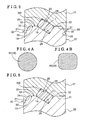
- Fig. 2 is a front view illustrating a roller dice device
- Fig. 3 is an enlarged view illustrating a main portion
- Fig. 4A is a cross-sectional view illustrating a wire that is not yet rolled
- Fig. 4B is a cross-sectional view illustrating a wire that has been rolled.
- Fig. 5 is an enlarged view illustrating a main portion according to a second embodiment.
- Embodiments of a roller dice device A, a method for manufacturing an insulator coil and a winding apparatus B will be described hereinafter with reference to the attached drawings.
- Fig. 1 illustrates the winding apparatus B for manufacturing the insulator coil.
- a first wire W1 (a wire for an insulator coil, a rolling material) is rolled to be formed into a second wire W2 (a rolled wire), having a substantially rectangular-shaped cross section, and then the second wire W2 is wound around a bobbin 6.
- the winding apparatus B includes the roller dice device A.
- the winding apparatus B includes, from an upstream in a reeling off direction of a wire W (i.e. from a front side of the winding apparatus B), a servo tension device 1, a tension measure 2, the roller dice device A, a winding speed measuring device 4, a nozzle unit 5, a spindle unit 7 and a tension device 3.
- the servo tension device 1 is a wire reeling device for reeling off the first wire W1, having a circular-shaped cross-section.
- the tension measure 2 detects a tension of the first wire W1.
- the roller dice device A rolls the first wire W1, having a substantially circular-shaped cross-section, to be formed into a second wire W2, having the substantially rectangular-shaped cross-section.
- the winding speed measuring device 4 detects a winding speed of the second wire W2.
- the nozzle unit 5 directs the second wire W2, which flows through the nozzle unit 5.
- the spindle unit 7 (a winding device) winds the second wire W2 around the bobbin 6 so as to form the insulator coil.
- the tension device 3 (a tension adjusting device) adjusts a tension of the second wire W2, which flows from the roller dice device A to the spindle unit 7.
- a tying device 8 for tying up the second wire W2 is provided between the nozzle unit 5 and the spindle unit 7.
- the tension measure 2, the tension device 3 and the tying device 8, for example may be selectively provided.
- the servo tension device 1 is provided at a front side of the winding device B while the spindle unit 7 is provided at a rear side of the winding device B.
- Directions, such as front, rear, left and right used hereinafter correspond to front, rear, left and right sides of the winding device B, respectively.
- a manufacturing operation for manufacturing the insulator coil performed by the winding apparatus B includes a wire supplying process, a rolling process and a winding process.
- the processes are performed as a single-series operation, in which the wire W (the first and second wires W1, W2) are neither removed nor placed in a middle of the operation.
- the wire supplying process is a process for reeling off the first wire W1 by means of the servo tension device 1 and supplying the reeled first wire W1 to the roller dice device A.
- the rolling process is a process for rolling the first wire W1 to be formed into the second wire W2, having the rectangular-shaped cross-section, by means of the roller dice device A.
- the winding process is a process for winding the second wire W2 around the bobbin 6 by means of the spindle unit 7 so as to form the insulator coil.
- the reeling process may not be necessarily provided and the first wire W1 may be supplied only when a tension of the first wire W1 exceeds a predetermined value.
- the first wire W1 having the circular-shaped cross-section, is supplied from a wire supplying reel, and is wound around the servo tension device 1.
- the servo tension device 1 includes a first reeling roller 9, a second reeling roller 10 and a tension roller 11.
- the reeling rollers 9, 10 reel off the first wire W1 when one of the reeling rollers 9, 10 is driven by a servo motor.
- the reeled first wire W1 is wound around the tension roller 11 that is provided at an upper side of the reeling rolls 9, 10.
- the tension roller 11 includes a spring 13, which is held by a low-friction cylinder 12 to be movable in a front-rear direction.
- the tension roller 11 applies tension to the first wire W1 by means of the spring 13.
- the tension roller 11 reels off the first wire W1 from an upper portion thereof toward a rear direction.
- the tension roller 11 stabilizes the tension of the first wire W1 specifically when a winding speed is high.
- the tension measure 2 includes a front roller 14, an intermediate roller 15 and a rear roller 16, around each of which the first wire W1, reeled off from the tension roller 11, is wound.
- the first wire W1 is wound around an upper side of the front roller 14, a lower side of the intermediate roller 15 and an upper side of the rear roller 16.
- Each of the rollers 9, 10 of the servo tension device 1 and each of the rollers 14, 15, 16 of the tension measure 2 is formed with a groove, having a semicircular-shaped cross-section, at each outer circumferential portion thereof, so that the first wire W1, having the circular-shaped cross-section, is guided without getting damaged.
- the roller dice device A as illustrated in Figs. 2 and 3 includes a pair of rolling rollers 21, 22 (an upper rolling roller 21 and a lower rolling roller 22), a first rotational shaft 23, a second rotational shaft 24 and a supporting frame (a supporting portion) 27.
- the pair of rolling rollers 21, 22 are respectively formed with first and second circumferential rolling grooves 17, 18 at first and second outer circumferential surfaces 19, 20 thereof.
- the pair of rolling rollers 21, 22 are respectively fixed to the rotational shaft 23, 24 by means of bolts so as to be attached/detached.
- the supporting frame 27 respectively rotatably supports the rotational shafts 23, 24 of the pair of rolling rollers 21, 22 around first and second roller axes X1, X2, which extend in a horizontal direction to be parallel with each other, via first and second bearings 25, 26, respectively.
- the pair of rolling rollers 21, 22 are rotatably supported by the supporting frame 27 via the rotational shafts 23, 24 and the first and second bearings 25, 26, so that the outer circumferential surfaces 19, 20 thereof contact each other in a radial direction of the rolling rollers 21, 22.
- a spaced portion, formed by the circumferential rolling grooves 17, 18 facing each other, is configured by a rolling portion 28, through which the wire W moves.
- the circumferential rolling grooves 17, 18 of the pair of rolling rollers 21, 22 are coated by a coating material in order to improve abrasion resistance and slidability.
- the pair of rolling rollers 21, 22 are supported so that the lower rolling roller 22 is driven to rotate by means of a servo motor while the upper rolling roller 21 is driven to rotate when the upper rolling roller 21 contacts the wire W moving through the rolling portion 28.
- Each of the circumferential rolling grooves 17, 18 is formed to have a substantially right-triangle-shaped cross-section so that the rolling portion 28 is formed into a substantially rectangular-shaped hole when seen in a moving direction of the wire W.
- each of the circumferential rolling grooves 17, 18 is formed to have substantially the same inequilateral-right-triangle-shaped cross-section, and first and second corner portions 29 of bottom surfaces of the inequilateral-right-triangle-shaped circumferential rolling grooves 17, 18 are displaced in a width direction of the circumferential rolling grooves 17, 18.
- first wire W1 having the circular-shaped cross-section
- second wire W2 having the rectangular-shaped cross-section whose corner portions are rounded.
- a restricting portion 30 is formed at the outer circumferential surfaces 19, 20 of the pair of the rolling rollers 21, 22.
- the restricting portion 30 restricts displacement of the pair of rolling rollers 21, 22 relative to each other in an axial direction of the roller axes X1, X2.
- the first outer circumferential surface 19 of the upper rolling roller 21 and the second outer circumferential surface 20 of the lower rolling roller 22 are engaged with each other in the radial direction of the rolling rollers 21, 22 at the rolling portion 28.
- the restricting portion 30 is configured to restrict the displacement of the pair of rolling rollers 21, 22 in the axial direction.
- the first outer circumferential surface 19 of the upper rolling roller 21 is formed with a groove that is formed into a substantially trapezoid shape when seen in the cross-sectional view.
- the first outer circumferential surface 19 of the upper rolling roller 21 includes a first cylindrical surface 31 whose width extends in parallel with the first roller axis X1, and left and right outer taper surfaces 33, which respectively extend along ends (circumferences) of the first cylindrical surface 31 toward radially outer direction of the upper rolling roller 21 so as to be inclined relative to the radial direction of the upper rolling roller 21 by the same angle.
- the second outer circumferential surface 20 of the lower rolling roller 22 is formed with a second cylindrical surface 32 whose width extends in parallel with the second roller axis X2 for the same length as the first cylindrical surface 31, and left and right inner taper surfaces 34, which respectively extend along ends (circumferences) of the second cylindrical surface 32 in the radially inner direction of the lower rolling roller 22 so as to be inclined relative to the radial direction of the lower rolling roller 22 by the same angle as the outer taper surfaces 33 of the upper rolling roller 21.
- the second outer circumferential surface 20 of the lower rolling roller 22 is engaged with the first outer circumferential surface 19 of the upper rolling roller 21 at the rolling portion 28.
- the circumferential rolling grooves 17, 18 are formed at the cylindrical surfaces 31, 32, respectively.
- the restricting portion 30 may be modified to be configured as follows. Instead of forming the left and right outer taper surfaces 33, left and right first right-angled surfaces, which extend orthogonally relative to the first cylindrical surface 31, may be formed at the upper rolling roller 21, Further, instead of forming the left and right inner taper surfaces 34, left and right second right-angled surfaces, which extend orthogonally relative to the second cylindrical surface 32, may be formed at the lower rolling roller 22. Then, a portion between the second right-angled surfaces of the lower rolling roller 22 may be inserted between the first right-angled surfaces of the upper rolling roller 21 so that the first and second right-angled surfaces engage with each other. Thus, the restricting portion restricts displacement of the pair of rolling rollers 21, 22 relative to each other in an axial direction of the roller axes X1, X2.
- the restricting portion 30, having the inner taper surfaces 33 and the outer taper surfaces 34 requires less driving load, and accordingly, a roller driving mechanism requires less output power.
- the restricting portion, having the right-angled surfaces the first right-angled surfaces of the upper rolling roller 21 and the second right-angled surfaces of the lower rolling roller 22 contact each other in plane. Therefore, large sliding resistance is generated when the pair of the rolling rollers 21, 22 rotates, and as a result, a large driving load is required.
- the inner taper surfaces 33 and the outer taper surfaces 34 contact each other in line in the radial direction of the rolling rollers 21, 22. Therefore, smaller sliding resistance is generated when the pair of the rolling rollers 21, 22 rotate, and as a result, less driving load is required.
- Fig. 5 illustrates a second embodiment of the restricting portion 30.
- the first outer circumferential surface 19 of the upper rolling roller 21 is formed with a first cylindrical surface 31, whose width extends in parallel with the first rolling axis X1, and outer taper surface 33, which extends along one end (one of circumferences) of the first cylindrical surface 31 in the radially outer direction of the upper rolling roller 21 so as to be inclined relative to the radial direction of the upper rolling roller 21.
- the second outer circumferential surface 20 of the lower rolling roller 22 is formed with a second cylindrical surface 32, whose width extends in parallel with the second rolling axis X2 for the same length as the first cylindrical surface 31, and an inner taper surface 34, which extends along one end (one of circumferences) of the second cylindrical surface 32 in the radially inner direction of the lower rolling roller 22 so as to be inclined relative to the radial direction of the rolling roller by the same angle as the outer taper surface 33 of the upper rolling roller 21.
- the outer taper surface 33 of the upper rolling roller 21 contacts the inner taper surface 34 of the lower rolling roller 22 in the axial direction of the roller axes X1, X2 at one side of the rolling portion 28 in a width direction of the groove.
- the restricting portion 30 is configured to restrict the displacement of the pair of rolling rollers 21, 22 in the axial direction.
- Other configurations of the restricting portion 30 are the same as the first embodiment.
- the pair of rolling rollers may be rotatably supported so that the outer circumferential surfaces thereof do not contact each other.
- the restricting portion may be modified so that a ring-shaped protruding portion, formed at one of the outer circumferential surfaces engages with a ring-shaped recessed-portion, formed at the other of the outer circumferential surfaces.
- the restricting portion may be thus configured to restrict the displacement of the pair of rolling rollers in the axial direction.
- the restricting portion may be modified so that tooth portions, formed at one of the outer circumferential surfaces so as to include the same interval between each other in a circumferential direction of the rolling roller, engage with a ring-shaped recessed-portion, formed at the other of the outer circumferential surfaces (or, recessed portions, formed at the other of the outer circumferential surfaces so as to include the same interval between each other in the circumferential direction of the rolling roller).
- the restricting portion may be thus configured to restrict the displacement of the pair of rolling rollers in the axial direction.
- the roller dice device may be used to process a metal-made rolling material other than a metal wire rod.
- the roller dice device may be used to process a tubular-shaped metal rolling material.
- the restricting portion may be modified as follows: one of the outer circumferential surfaces is formed with a first cylindrical surface, whose width extends in parallel with the axial direction of the rolling roller, and a pair of outer taper surfaces, which respectively extend along ends (circumferences) of the first cylindrical surface in the radially outer direction of the rolling roller so as to be inclined relative to the radial direction of the rolling roller.
- the other of the outer circumferential surfaces is formed with a second cylindrical surface, whose width extends in parallel with the axial direction of the rolling roller, and one inner taper surface, which extends along one end (one of circumferences) of the second cylindrical surface in the radially inner direction of the rolling roller so as to be inclined relative to the radial direction of the rolling roller.
- the restricting portion may be thus configured to restrict the displacement of the pair of rolling rollers in the axial direction.
- a roller dice device (A) includes a pair of rolling rollers (21, 22) respectively including circumferential rolling grooves (17, 18) formed at outer circumferential surfaces (19, 20) thereof, a supporting portion (27) rotatably supporting the pair of rolling rollers (21, 22) respectively around roller axes (X1, X2) extending in parallel with each other, a spaced portion configured by a rolling portion (28), through which a rolling material moves, and formed by the circumferential rolling grooves (17, 18) facing each other, and a restricting portion (30) formed at the outer circumferential surfaces (19, 20) of the pair of the rolling rollers (21, 22) and restricting displacement of the pair of rolling rollers (19, 20) relative to each other in the axial direction of the roller axes (X1, X2).
Landscapes
- Engineering & Computer Science (AREA)
- Mechanical Engineering (AREA)
- Coil Winding Methods And Apparatuses (AREA)
- Manufacture Of Motors, Generators (AREA)
- Metal Rolling (AREA)
- Metal Extraction Processes (AREA)
Abstract
Description
- The present invention relates to a roller dice device including a pair of rolling rollers respectively including circumferential rolling grooves formed at outer circumferential surfaces thereof, a supporting portion rotatably supporting the pair of rolling rollers respectively around roller axes extending in parallel with each other, and a spaced portion configured by a rolling portion, through which a rolling material moves, and formed by the circumferential rolling grooves facing each other.
- A rolling material may not be processed accurately by means of a roller dice device, in a case where circumferential rolling grooves of a pair of rolling rollers are displaced relative to each other in a width direction of the grooves. A roller dice device is disclosed in
JP10-225713A JP2007-220490 - According to
JP10-225713A JP2007-220490 - A need thus exists for a roller dice device, a method for manufacturing an insulator coil and a winding apparatus, in which when a rolling material moves through a rolling portion, circumferential rolling grooves of a pair of rolling roller are less likely to be displaced relative to each other in a width direction of the grooves, and in which accuracy in processing a rolling material may be maintained appropriately.
- According to an aspect of the invention a roller dice device includes a pair of rolling rollers respectively including circumferential rolling grooves formed at outer circumferential surfaces thereof, a supporting portion rotatably supporting the pair of rolling rollers respectively around roller axes extending in parallel with each other, a spaced portion configured by a rolling portion, through which a rolling material moves, and formed by the circumferential rolling grooves facing each other, and a restricting portion formed at the outer circumferential surfaces of the pair of the rolling rollers and restricting displacement of the pair of rolling rollers relative to each other in the axial direction of the roller axes.
- Accordingly, when a rolling material moves through a rolling portion, a reaction force, which includes a component force in the axial direction of the roller, may be applied to each of the circumferential rolling grooves of the pair of rolling rollers. However, the circumferential rolling grooves are less likely to be displaced relative to each other in the width direction of the grooves. As a result, the rolling material is processed accurately so as to have a desired-shaped cross-section.
- According to another aspect of the present invention, the pair of rolling rollers is rotatably supported in a manner where the outer circumferential surfaces thereof contact each other. Each of the circumferential rolling grooves is formed to have a right-triangle-shaped cross-section so that the spaced portion is formed into a rectangular-shaped hole when seen in a moving direction of the rolling material.
- Accordingly, the rolling material may be processed to have the rectangular-shaped cross-section. When an insulator electric wire, processed in the roller dice device, is wound around an insulator member so as to form a,coil, less clearance is generated in the wound electric coil. Consequently, a coil may be formed, which have the rectangular-shaped cross-section so as to include a high space factor. "Rectangular" mentioned herein refers to a quadrangle, which has four straight sides and four 90-degree angles, such as a square having four equal sides, or a rectangle having two longer sides and two shorter sides.
- According to a further aspect of the present invention, the restricting portion includes a first cylindrical surface formed at one of the outer circumferential surfaces to be in parallel with the roller axes, an outer taper surface extending along an end of the first cylindrical surface toward a radially outer direction of one of the rolling rollers, a second cylindrical surface formed at the other of the outer circumferential surfaces to be in parallel with the roller axes, and an inner taper surface extending along an end of the second cylindrical surface toward a radially inner direction of one of the rolling rollers. The outer taper surface contacts the inner taper surface in the axial direction of the roller axes so that the restricting portion restricts the displacement of the pair of rolling rollers.
- Accordingly, the rolling material may be processed to have the rectangular-shaped cross-section. In order to form the rolling material to have the rectangular-shaped cross-section by means of the circumferential rolling grooves, having right-triangle-shaped cross-section, two inequilateral right triangle shapes of the circumferential rolling grooves form a rectangular shape when seen in the cross-sectional view thereof. Therefore, while the rolling material, having the circular-shaped cross-section, moves through the rolling portion, a larger reaction force may be generated at the longer sides of the circumferential rolling grooves. Consequently, the circumferential rolling grooves may easily be displaced at the rolling portion in a direction where the corner portions of the bottom surfaces of the circumferential rolling grooves approach close to each other. Further, even in a case where each of the circumferential rolling grooves is formed into an isosceles right triangle shape when seen in the cross-sectional view thereof, depending on forming conditions and accuracy of assembly of the rolling rollers, the pair of rolling rollers may be displaced relative to each other in a width direction of the circumferential rolling grooves. Accordingly, the circumferential rolling grooves may be displaced relative to each other at the rolling portion in the direction where corner portions of the bottom surfaces of the circumferential rolling grooves approach close to each other. Therefore, according to the first and second embodiments, the restricting portion is provided, which includes the first cylindrical surface formed at one of the outer circumferential surfaces to be in parallel with the roller axes, the outer taper surface extending along the end of the first cylindrical surface toward the radially outer direction of one of the rolling rollers, the second cylindrical surface formed at the other of the outer circumferential surfaces to be in parallel with the roller axes, and the inner taper surface extending along the end of the first cylindrical surface toward the radially inner direction of one of the rolling rollers. Consequently, the outer taper surface contacts the inner taper surface in the axial direction of the roller axes so that the restricting portion restricts the displacement of the pair of rolling rollers, Accordingly, displacement of the circumferential groove portions relative to each other in the width direction of the grooves is less likely to occur and the rolling material may be more accurately formed to have the rectangular-shaped cross-section.
- According to a further aspect of the present invention, the restricting portion includes the first cylindrical surface formed at one of the outer circumferential surfaces to be in parallel with the roller axes and formed at both side of the rolling roller in a direction of the rollers axes, the outer taper surface extending along both ends of the first cylindrical surface in the direction of the rollers axes toward a radially outer direction of one of the rolling rollers, the second cylindrical surface formed at the other of the outer circumferential surfaces to be in parallel with the roller axes and formed at both side of the rolling roller in the direction of the rollers axes, and the inner taper surface extending along both ends of the second cylindrical surface in the direction of the rollers axes toward a radially inner direction of one of the rolling rollers.
- According to a further aspect of the present invention, a winding apparatus, having the roller dice device includes the roller dice device, the winding device winding a rolled wire, rolled to have a rectangular-shaped cross-section by means of the roller device, around a bobbin, and a tension adjusting device adjusting a tension of the rolled wire, moving from the roller dice device to the winding device.
- Accordingly, the rolling wire, having the rectangular-shaped cross-section, is accurately formed. Further, when the rolling wire is wound to form the insulator coil, a coil, which includes a high space factor, may be more easily manufactured.
- According to a further aspect of the present invention, the method for manufacturing an insulator coil, using the roller dice device includes the wire supplying process for supplying the wire for the insulator coil to the rolling portion, the rolling process for rolling the wire, supplied to the rolling portion, to have a rectangular-shaped cross-section, and the winding process for winding the rolled wire, rolled to have the substantially rectangular-shaped cross-section in the rolling process, so as to form the insulator coil.
- Accordingly, the pair of rolling rollers each of which has the right-triangle-shaped circumferential rolling groove is used so that the rolling portion is formed into the rectangular-shaped hole when seen in the cross-sectional view thereof. Therefore, when seen in the cross-sectional view, a contacting surface, where the pair of rolling rollers contacts each other, is positioned at an extension of a diagonal line of the rectangular-shaped cross-section of the rolling wire. Accordingly, the contacting surface of the pair of the rolling rollers is positioned at the corner portions of the rectangular-shaped wire. As a result, deformation of a cross-section of the wire due to a rolling force is less likely to occur.
- The foregoing and additional features and characteristics of the disclosure will become more apparent from the following detailed description considered with the reference to the accompanying drawings, wherein:
-
Fig. 1A is a planar view illustrating a winding apparatus; -
Fig. 1B is a side view illustrating the winding apparatus; -
Fig. 2 is a front view illustrating a roller dice device; -
Fig. 3 is an enlarged view illustrating a main portion; -
Fig. 4A is a cross-sectional view illustrating a wire that is not yet rolled; -
Fig. 4B is a cross-sectional view illustrating a wire that has been rolled; and -
Fig. 5 is an enlarged view illustrating a main portion according to a second embodiment. - Embodiments of a roller dice device A, a method for manufacturing an insulator coil and a winding apparatus B will be described hereinafter with reference to the attached drawings.
-
Fig. 1 illustrates the winding apparatus B for manufacturing the insulator coil. In order to manufacture the insulator coil, a first wire W1 (a wire for an insulator coil, a rolling material) is rolled to be formed into a second wire W2 (a rolled wire), having a substantially rectangular-shaped cross section, and then the second wire W2 is wound around abobbin 6. The winding apparatus B includes the roller dice device A. - The winding apparatus B includes, from an upstream in a reeling off direction of a wire W (i.e. from a front side of the winding apparatus B), a servo tension device 1, a tension measure 2, the roller dice device A, a winding speed measuring device 4, a
nozzle unit 5, a spindle unit 7 and a tension device 3. The servo tension device 1 is a wire reeling device for reeling off the first wire W1, having a circular-shaped cross-section. The tension measure 2 detects a tension of the first wire W1. The roller dice device A rolls the first wire W1, having a substantially circular-shaped cross-section, to be formed into a second wire W2, having the substantially rectangular-shaped cross-section. The winding speed measuring device 4 detects a winding speed of the second wire W2. Thenozzle unit 5 directs the second wire W2, which flows through thenozzle unit 5. The spindle unit 7 (a winding device) winds the second wire W2 around thebobbin 6 so as to form the insulator coil. The tension device 3 (a tension adjusting device) adjusts a tension of the second wire W2, which flows from the roller dice device A to the spindle unit 7. - A tying
device 8 for tying up the second wire W2 is provided between thenozzle unit 5 and the spindle unit 7. However, not limited to the first embodiment described herein, the tension measure 2, the tension device 3 and the tyingdevice 8, for example, may be selectively provided. - The servo tension device 1 is provided at a front side of the winding device B while the spindle unit 7 is provided at a rear side of the winding device B. Directions, such as front, rear, left and right used hereinafter correspond to front, rear, left and right sides of the winding device B, respectively.
- A manufacturing operation for manufacturing the insulator coil performed by the winding apparatus B includes a wire supplying process, a rolling process and a winding process. The processes are performed as a single-series operation, in which the wire W (the first and second wires W1, W2) are neither removed nor placed in a middle of the operation. The wire supplying process is a process for reeling off the first wire W1 by means of the servo tension device 1 and supplying the reeled first wire W1 to the roller dice device A. The rolling process is a process for rolling the first wire W1 to be formed into the second wire W2, having the rectangular-shaped cross-section, by means of the roller dice device A. The winding process is a process for winding the second wire W2 around the
bobbin 6 by means of the spindle unit 7 so as to form the insulator coil. However, not limited to the first embodiment, the reeling process, for example, may not be necessarily provided and the first wire W1 may be supplied only when a tension of the first wire W1 exceeds a predetermined value. - The first wire W1, having the circular-shaped cross-section, is supplied from a wire supplying reel, and is wound around the servo tension device 1. The servo tension device 1 includes a first reeling
roller 9, a second reelingroller 10 and atension roller 11. The reelingrollers rollers tension roller 11 that is provided at an upper side of the reelingrolls - The
tension roller 11 includes aspring 13, which is held by a low-friction cylinder 12 to be movable in a front-rear direction. Thetension roller 11 applies tension to the first wire W1 by means of thespring 13. - The
tension roller 11 reels off the first wire W1 from an upper portion thereof toward a rear direction. Thetension roller 11 stabilizes the tension of the first wire W1 specifically when a winding speed is high. - The tension measure 2 includes a
front roller 14, anintermediate roller 15 and arear roller 16, around each of which the first wire W1, reeled off from thetension roller 11, is wound. The first wire W1 is wound around an upper side of thefront roller 14, a lower side of theintermediate roller 15 and an upper side of therear roller 16. - Each of the
rollers rollers - The roller dice device A, as illustrated in
Figs. 2 and3 includes a pair of rollingrollers 21, 22 (anupper rolling roller 21 and a lower rolling roller 22), a firstrotational shaft 23, a secondrotational shaft 24 and a supporting frame (a supporting portion) 27. The pair of rollingrollers circumferential rolling grooves circumferential surfaces rollers rotational shaft frame 27 respectively rotatably supports therotational shafts rollers second bearings - The pair of rolling
rollers frame 27 via therotational shafts second bearings circumferential surfaces rollers Fig. 3 , a spaced portion, formed by thecircumferential rolling grooves portion 28, through which the wire W moves. - The
circumferential rolling grooves rollers - The pair of rolling
rollers lower rolling roller 22 is driven to rotate by means of a servo motor while the upper rollingroller 21 is driven to rotate when the upper rollingroller 21 contacts the wire W moving through the rollingportion 28. - Each of the
circumferential rolling grooves portion 28 is formed into a substantially rectangular-shaped hole when seen in a moving direction of the wire W. - More specifically, in order to form the rolling
portion 28 in the rectangular-shaped hole when seen in the moving direction of the wire W, each of thecircumferential rolling grooves second corner portions 29 of bottom surfaces of the inequilateral-right-triangle-shapedcircumferential rolling grooves circumferential rolling grooves - While the first wire W1, having the circular-shaped cross-section, is moving through the rolling
portion 28 as illustrated inFig. 4A , the first wire W1 is rolled to be formed into the second wire W2, having the rectangular-shaped cross-section whose corner portions are rounded. - A restricting
portion 30 is formed at the outercircumferential surfaces rollers portion 30 restricts displacement of the pair of rollingrollers - The first outer
circumferential surface 19 of the upper rollingroller 21 and the second outercircumferential surface 20 of thelower rolling roller 22 are engaged with each other in the radial direction of the rollingrollers portion 28. Thus, the restrictingportion 30 is configured to restrict the displacement of the pair of rollingrollers - The first outer
circumferential surface 19 of the upper rollingroller 21 is formed with a groove that is formed into a substantially trapezoid shape when seen in the cross-sectional view. The first outercircumferential surface 19 of the upper rollingroller 21 includes a firstcylindrical surface 31 whose width extends in parallel with the first roller axis X1, and left and right outer taper surfaces 33, which respectively extend along ends (circumferences) of the firstcylindrical surface 31 toward radially outer direction of the upper rollingroller 21 so as to be inclined relative to the radial direction of the upper rollingroller 21 by the same angle. - The second outer
circumferential surface 20 of thelower rolling roller 22 is formed with a secondcylindrical surface 32 whose width extends in parallel with the second roller axis X2 for the same length as the firstcylindrical surface 31, and left and right inner taper surfaces 34, which respectively extend along ends (circumferences) of the secondcylindrical surface 32 in the radially inner direction of thelower rolling roller 22 so as to be inclined relative to the radial direction of thelower rolling roller 22 by the same angle as the outer taper surfaces 33 of the upper rollingroller 21. Thus, the second outercircumferential surface 20 of thelower rolling roller 22 is engaged with the first outercircumferential surface 19 of the upper rollingroller 21 at the rollingportion 28. Further, thecircumferential rolling grooves cylindrical surfaces - The restricting
portion 30 may be modified to be configured as follows. Instead of forming the left and right outer taper surfaces 33, left and right first right-angled surfaces, which extend orthogonally relative to the firstcylindrical surface 31, may be formed at the upper rollingroller 21, Further, instead of forming the left and right inner taper surfaces 34, left and right second right-angled surfaces, which extend orthogonally relative to the secondcylindrical surface 32, may be formed at thelower rolling roller 22. Then, a portion between the second right-angled surfaces of thelower rolling roller 22 may be inserted between the first right-angled surfaces of the upper rollingroller 21 so that the first and second right-angled surfaces engage with each other. Thus, the restricting portion restricts displacement of the pair of rollingrollers - However, compared to the restricting portion, having the right-angled surfaces, the restricting
portion 30, having the inner taper surfaces 33 and the outer taper surfaces 34, requires less driving load, and accordingly, a roller driving mechanism requires less output power. In other words, according to the restricting portion, having the right-angled surfaces, the first right-angled surfaces of the upper rollingroller 21 and the second right-angled surfaces of thelower rolling roller 22 contact each other in plane. Therefore, large sliding resistance is generated when the pair of the rollingrollers portion 30, having the inner taper surfaces 33 and the outer taper surfaces 34, the inner taper surfaces 33 and the outer taper surfaces 34 contact each other in line in the radial direction of the rollingrollers rollers -
Fig. 5 illustrates a second embodiment of the restrictingportion 30. The first outercircumferential surface 19 of the upper rollingroller 21 is formed with a firstcylindrical surface 31, whose width extends in parallel with the first rolling axis X1, andouter taper surface 33, which extends along one end (one of circumferences) of the firstcylindrical surface 31 in the radially outer direction of the upper rollingroller 21 so as to be inclined relative to the radial direction of the upper rollingroller 21. - The second outer
circumferential surface 20 of thelower rolling roller 22 is formed with a secondcylindrical surface 32, whose width extends in parallel with the second rolling axis X2 for the same length as the firstcylindrical surface 31, and aninner taper surface 34, which extends along one end (one of circumferences) of the secondcylindrical surface 32 in the radially inner direction of thelower rolling roller 22 so as to be inclined relative to the radial direction of the rolling roller by the same angle as theouter taper surface 33 of the upper rollingroller 21. - The
outer taper surface 33 of the upper rollingroller 21 contacts theinner taper surface 34 of thelower rolling roller 22 in the axial direction of the roller axes X1, X2 at one side of the rollingportion 28 in a width direction of the groove. Thus, the restrictingportion 30 is configured to restrict the displacement of the pair of rollingrollers portion 30 are the same as the first embodiment. - According to the roller dice device, the pair of rolling rollers may be rotatably supported so that the outer circumferential surfaces thereof do not contact each other.
- According to the roller dice device, the restricting portion may be modified so that a ring-shaped protruding portion, formed at one of the outer circumferential surfaces engages with a ring-shaped recessed-portion, formed at the other of the outer circumferential surfaces. The restricting portion may be thus configured to restrict the displacement of the pair of rolling rollers in the axial direction.
- According to the roller dice device, the restricting portion may be modified so that tooth portions, formed at one of the outer circumferential surfaces so as to include the same interval between each other in a circumferential direction of the rolling roller, engage with a ring-shaped recessed-portion, formed at the other of the outer circumferential surfaces (or, recessed portions, formed at the other of the outer circumferential surfaces so as to include the same interval between each other in the circumferential direction of the rolling roller). The restricting portion may be thus configured to restrict the displacement of the pair of rolling rollers in the axial direction.
- The roller dice device may be used to process a metal-made rolling material other than a metal wire rod.
- The roller dice device may be used to process a tubular-shaped metal rolling material.
- According to the roller dice device, the restricting portion may be modified as follows: one of the outer circumferential surfaces is formed with a first cylindrical surface, whose width extends in parallel with the axial direction of the rolling roller, and a pair of outer taper surfaces, which respectively extend along ends (circumferences) of the first cylindrical surface in the radially outer direction of the rolling roller so as to be inclined relative to the radial direction of the rolling roller. The other of the outer circumferential surfaces is formed with a second cylindrical surface, whose width extends in parallel with the axial direction of the rolling roller, and one inner taper surface, which extends along one end (one of circumferences) of the second cylindrical surface in the radially inner direction of the rolling roller so as to be inclined relative to the radial direction of the rolling roller. The restricting portion may be thus configured to restrict the displacement of the pair of rolling rollers in the axial direction.
A roller dice device (A) includes a pair of rolling rollers (21, 22) respectively including circumferential rolling grooves (17, 18) formed at outer circumferential surfaces (19, 20) thereof, a supporting portion (27) rotatably supporting the pair of rolling rollers (21, 22) respectively around roller axes (X1, X2) extending in parallel with each other, a spaced portion configured by a rolling portion (28), through which a rolling material moves, and formed by the circumferential rolling grooves (17, 18) facing each other, and a restricting portion (30) formed at the outer circumferential surfaces (19, 20) of the pair of the rolling rollers (21, 22) and restricting displacement of the pair of rolling rollers (19, 20) relative to each other in the axial direction of the roller axes (X1, X2).
Claims (6)
- A roller dice device (A) comprising:a pair of rolling rollers (21, 22) respectively including circumferential rolling grooves (17,18) formed at outer circumferential surfaces (19, 20) thereof;a supporting portion (27) rotatably supporting the pair of rolling rollers (21, 22) respectively around roller axes (X1, X2) extending in parallel with each other;a spaced portion configured by a rolling portion (28), through which a rolling material moves, and formed by the circumferential rolling grooves (17, 18) facing each other, anda restricting portion (30) formed at the outer circumferential surfaces (19, 20) of the pair of the rolling rollers (21, 22) and restricting displacement of the pair of rolling rollers (19, 20) relative to each other in the axial direction of the roller axes (X1, X2).
- The roller dice device (A) according to claim 1, wherein
the pair of rolling rollers (21, 22) is rotatably supported in a manner where the outer circumferential surfaces (19, 20) thereof contact each other, and wherein
each of the circumferential rolling grooves (17, 18) is formed to have a right-triangle-shaped cross-section so that the spaced portion is formed into a rectangular-shaped hole when seen in a moving direction of the rolling material. - The roller dice device (A) according to claim 2, wherein
the restricting portion (30) includes
a first cylindrical surface (31) formed at one of the outer circumferential surfaces (19, 20) to be in parallel with the roller axes (X1, X2),
an outer taper surface (33) extending along an end of the first cylindrical surface (31) toward a radially outer direction of one of the rolling rollers (21, 22),
a second cylindrical surface (32) formed at the other of the outer circumferential surfaces (19, 20) to be in parallel with the roller axes (X1, X2), and
an inner taper surface (34) extending along an end of the first cylindrical surface (32) toward a radially inner direction of one of the rolling rollers (21, 22), and wherein
the outer taper surface (33) contacts the inner taper surface (34) in the axial direction of the roller axes (X1, X2) so that the restricting portion (30) restricts the displacement of the pair of rolling rollers (21, 22). - The roller dice device (A) according to claim 3, wherein
the restricting portion (30) includes
the first cylindrical surface (31) formed at one of the outer circumferential surfaces( 19, 20) to be in parallel with the roller axes and formed at both side of the rolling roller in a direction of the rollers axes (X1, X2),
the outer taper surface (33) extending along both ends of the first cylindrical surface (31) in the direction of the rollers axes toward a radially outer direction of one of the rolling rollers (21,22),
the second cylindrical surface (32) formed at the other of the outer circumferential surfaces (19, 20) to be in parallel with the roller axes and formed at both side of the rolling roller in the direction of the rollers axes (X1, X2), and
the inner taper surface (34) extending along both ends of the second cylindrical surface (32) in the direction of the rollers axes (X1, X2) toward a radially inner direction of one of the rolling rollers (21, 22). - A winding apparatus (B), having the roller dice device (A) according to any one of claims 2 through 4, comprising:the roller dice device (A);the winding device (7) winding a rolled wire, rolled to have a rectangular-shaped cross-section by means of the roller device (A), around a bobbin (6); anda tension adjusting device (3) adjusting a tension of the rolled wire, moving from the roller dice device (A) to the winding device (7).
- A method for manufacturing an insulator coil, using the roller dice device (A) according to any one of claims 2 through 4, comprising:a wire supplying process for supplying a wire for the insulator coil to the rolling portion (28);a rolling process for rolling the wire, supplied to the rolling portion (28), to have a rectangular-shaped cross-section; anda winding process for winding the rolled wire, rolled to have the substantially rectangular-shaped cross-section in the rolling process, so as to form the insulator coil.
Applications Claiming Priority (1)
| Application Number | Priority Date | Filing Date | Title |
|---|---|---|---|
| JP2008258868A JP2010089099A (en) | 2008-10-03 | 2008-10-03 | Roller die device, method for manufacturing insulator coil, and wire winding apparatus |
Publications (2)
| Publication Number | Publication Date |
|---|---|
| EP2172283A1 true EP2172283A1 (en) | 2010-04-07 |
| EP2172283B1 EP2172283B1 (en) | 2013-08-14 |
Family
ID=41508773
Family Applications (1)
| Application Number | Title | Priority Date | Filing Date |
|---|---|---|---|
| EP09171504.5A Not-in-force EP2172283B1 (en) | 2008-10-03 | 2009-09-28 | Roller dice device, method for manufacturing insulator coil and winding apparatus |
Country Status (3)
| Country | Link |
|---|---|
| US (1) | US8336357B2 (en) |
| EP (1) | EP2172283B1 (en) |
| JP (1) | JP2010089099A (en) |
Cited By (1)
| Publication number | Priority date | Publication date | Assignee | Title |
|---|---|---|---|---|
| CN113634593A (en) * | 2021-08-11 | 2021-11-12 | 常州时创能源股份有限公司 | Preparation method of triangular welding strip for photovoltaic |
Families Citing this family (2)
| Publication number | Priority date | Publication date | Assignee | Title |
|---|---|---|---|---|
| ES2980482T3 (en) | 2016-12-12 | 2024-10-01 | Siemens Ag | Procedure for winding a product to be wound and winding machine |
| CN119069254B (en) * | 2024-08-30 | 2025-10-17 | 武汉凌云光电科技有限责任公司 | Enameled wire shaping jig and method |
Citations (7)
| Publication number | Priority date | Publication date | Assignee | Title |
|---|---|---|---|---|
| DE92691C (en) * | ||||
| GB980362A (en) * | 1961-11-25 | 1965-01-13 | Moossche Eisenwerke Ag | Method of and apparatus for rolling out sections in one pass, and a rolling mill for carrying out the method |
| JPS5954110U (en) * | 1982-10-04 | 1984-04-09 | 住友金属工業株式会社 | Roller dice device |
| JPS5977507U (en) * | 1982-11-18 | 1984-05-25 | 住友金属工業株式会社 | Roller dice device |
| GB2156935A (en) * | 1984-03-30 | 1985-10-16 | Rolf Henning Wilhelm Steinbock | Apparatus for stressing fastener shanks |
| JPH10225713A (en) | 1997-02-17 | 1998-08-25 | Nippon Steel Weld Prod & Eng Co Ltd | Cassette type roller die and method of adjusting its assembly |
| JP2007220490A (en) | 2006-02-16 | 2007-08-30 | Mitsubishi Cable Ind Ltd | Method of manufacturing a square insulated wire, a square insulated wire manufactured thereby, and its use |
Family Cites Families (13)
| Publication number | Priority date | Publication date | Assignee | Title |
|---|---|---|---|---|
| US401692A (en) * | 1889-04-16 | Rolls for rolling bulb-webbed slot-rails | ||
| US1302497A (en) * | 1916-03-20 | 1919-05-06 | George H Barbour | Method of rolling flanged sections. |
| US2038908A (en) * | 1933-09-29 | 1936-04-28 | Scholl Joseph | Rolling of rectangular bars |
| US3488989A (en) * | 1967-09-27 | 1970-01-13 | Anaconda American Brass Co | Method of producing dual gauge strip |
| US4085490A (en) * | 1976-04-01 | 1978-04-25 | Ramsey Corporation | Method of making a rolled metal piston ring |
| JPS5954110A (en) | 1982-09-20 | 1984-03-28 | 昭和電線電纜株式会社 | Refractory of cable |
| JPS5977507A (en) | 1982-10-27 | 1984-05-04 | Yaskawa Electric Mfg Co Ltd | Sequence control device |
| JPH0613121B2 (en) * | 1986-08-06 | 1994-02-23 | 繁 小瀬 | Plastic forming method for hard steel wire |
| JP2503380B2 (en) * | 1991-02-04 | 1996-06-05 | 日立電線株式会社 | Flat wire manufacturing method |
| JP3613994B2 (en) * | 1998-02-12 | 2005-01-26 | トヨタ自動車株式会社 | Flat wire coil manufacturing apparatus and flat wire coil manufacturing method |
| EP1410667A1 (en) | 2001-07-18 | 2004-04-21 | Wizard Mobile Solutions Limited | Data security device |
| JP4481664B2 (en) * | 2004-01-20 | 2010-06-16 | 三菱電線工業株式会社 | Manufacturing method of flat insulated wire |
| KR100661222B1 (en) * | 2006-02-03 | 2006-12-22 | 엘에스전선 주식회사 | Wire rod manufacturing apparatus with rolling roller for flat wire rod |
-
2008
- 2008-10-03 JP JP2008258868A patent/JP2010089099A/en active Pending
-
2009
- 2009-09-28 US US12/568,095 patent/US8336357B2/en not_active Expired - Fee Related
- 2009-09-28 EP EP09171504.5A patent/EP2172283B1/en not_active Not-in-force
Patent Citations (7)
| Publication number | Priority date | Publication date | Assignee | Title |
|---|---|---|---|---|
| DE92691C (en) * | ||||
| GB980362A (en) * | 1961-11-25 | 1965-01-13 | Moossche Eisenwerke Ag | Method of and apparatus for rolling out sections in one pass, and a rolling mill for carrying out the method |
| JPS5954110U (en) * | 1982-10-04 | 1984-04-09 | 住友金属工業株式会社 | Roller dice device |
| JPS5977507U (en) * | 1982-11-18 | 1984-05-25 | 住友金属工業株式会社 | Roller dice device |
| GB2156935A (en) * | 1984-03-30 | 1985-10-16 | Rolf Henning Wilhelm Steinbock | Apparatus for stressing fastener shanks |
| JPH10225713A (en) | 1997-02-17 | 1998-08-25 | Nippon Steel Weld Prod & Eng Co Ltd | Cassette type roller die and method of adjusting its assembly |
| JP2007220490A (en) | 2006-02-16 | 2007-08-30 | Mitsubishi Cable Ind Ltd | Method of manufacturing a square insulated wire, a square insulated wire manufactured thereby, and its use |
Cited By (1)
| Publication number | Priority date | Publication date | Assignee | Title |
|---|---|---|---|---|
| CN113634593A (en) * | 2021-08-11 | 2021-11-12 | 常州时创能源股份有限公司 | Preparation method of triangular welding strip for photovoltaic |
Also Published As
| Publication number | Publication date |
|---|---|
| US20100084501A1 (en) | 2010-04-08 |
| US8336357B2 (en) | 2012-12-25 |
| EP2172283B1 (en) | 2013-08-14 |
| JP2010089099A (en) | 2010-04-22 |
Similar Documents
| Publication | Publication Date | Title |
|---|---|---|
| CN109414747B (en) | Roller press and rolling method of roller press | |
| EP3460881B1 (en) | Roll press machine with wrinkle prevention device, and roll press method | |
| US9653864B2 (en) | Wire straightening apparatus | |
| US8336357B2 (en) | Roller dice device, method for manufacturing insulator coil and winding apparatus | |
| JP2010125543A (en) | Bobbin for wire saw and wire saw | |
| EP4243257A1 (en) | Winding device | |
| WO1996010470A1 (en) | Wire saw | |
| JP5262289B2 (en) | Winding method and winding apparatus | |
| EP1977839A1 (en) | Dual pivot ironing roll | |
| JP2017064782A (en) | Manufacturing method for cutter metal bar coil | |
| JP5862288B2 (en) | Manufacturing method and manufacturing apparatus of flat wire coil | |
| JP4784440B2 (en) | Winding device | |
| JP6383692B2 (en) | Welded pipe manufacturing method and welded pipe manufacturing equipment | |
| JP2015501270A (en) | Device comprising a rotating arm for unwinding a strand of material | |
| EP4618382A1 (en) | Winding device | |
| JP2005139585A (en) | Method and apparatus for manufacturing steel wire rubber composite material | |
| JP3446094B2 (en) | Slitter system and slitting method | |
| JP2020014287A (en) | Winding device | |
| EP4618118A1 (en) | Winding device and winding method | |
| JP5915586B2 (en) | Steel strip meander control device and meander control method | |
| JP2013146749A (en) | Back-up roll for tension leveler device, tension leveler device using the back-up roll for the tension leveler device, and method for controlling the tension leveler device | |
| KR101528166B1 (en) | Apparatus for winding steel strip | |
| JP5575763B2 (en) | Unwinding assist device for wire | |
| JP2010125503A (en) | Wire rod feeding device | |
| JP2019195837A (en) | Roll bending device |
Legal Events
| Date | Code | Title | Description |
|---|---|---|---|
| PUAI | Public reference made under article 153(3) epc to a published international application that has entered the european phase |
Free format text: ORIGINAL CODE: 0009012 |
|
| AK | Designated contracting states |
Kind code of ref document: A1 Designated state(s): AT BE BG CH CY CZ DE DK EE ES FI FR GB GR HR HU IE IS IT LI LT LU LV MC MK MT NL NO PL PT RO SE SI SK SM TR |
|
| 17P | Request for examination filed |
Effective date: 20101005 |
|
| 17Q | First examination report despatched |
Effective date: 20110606 |
|
| GRAP | Despatch of communication of intention to grant a patent |
Free format text: ORIGINAL CODE: EPIDOSNIGR1 |
|
| RIC1 | Information provided on ipc code assigned before grant |
Ipc: B21B 27/03 20060101ALI20121207BHEP Ipc: B21C 3/08 20060101AFI20121207BHEP |
|
| GRAP | Despatch of communication of intention to grant a patent |
Free format text: ORIGINAL CODE: EPIDOSNIGR1 |
|
| INTG | Intention to grant announced |
Effective date: 20130522 |
|
| GRAS | Grant fee paid |
Free format text: ORIGINAL CODE: EPIDOSNIGR3 |
|
| GRAA | (expected) grant |
Free format text: ORIGINAL CODE: 0009210 |
|
| AK | Designated contracting states |
Kind code of ref document: B1 Designated state(s): AT BE BG CH CY CZ DE DK EE ES FI FR GB GR HR HU IE IS IT LI LT LU LV MC MK MT NL NO PL PT RO SE SI SK SM TR |
|
| REG | Reference to a national code |
Ref country code: GB Ref legal event code: FG4D |
|
| REG | Reference to a national code |
Ref country code: CH Ref legal event code: EP Ref country code: AT Ref legal event code: REF Ref document number: 626487 Country of ref document: AT Kind code of ref document: T Effective date: 20130815 |
|
| REG | Reference to a national code |
Ref country code: IE Ref legal event code: FG4D |
|
| REG | Reference to a national code |
Ref country code: DE Ref legal event code: R096 Ref document number: 602009017937 Country of ref document: DE Effective date: 20131010 |
|
| REG | Reference to a national code |
Ref country code: NL Ref legal event code: VDEP Effective date: 20130814 Ref country code: AT Ref legal event code: MK05 Ref document number: 626487 Country of ref document: AT Kind code of ref document: T Effective date: 20130814 |
|
| REG | Reference to a national code |
Ref country code: LT Ref legal event code: MG4D |
|
| PG25 | Lapsed in a contracting state [announced via postgrant information from national office to epo] |
Ref country code: HR Free format text: LAPSE BECAUSE OF FAILURE TO SUBMIT A TRANSLATION OF THE DESCRIPTION OR TO PAY THE FEE WITHIN THE PRESCRIBED TIME-LIMIT Effective date: 20130814 Ref country code: SE Free format text: LAPSE BECAUSE OF FAILURE TO SUBMIT A TRANSLATION OF THE DESCRIPTION OR TO PAY THE FEE WITHIN THE PRESCRIBED TIME-LIMIT Effective date: 20130814 Ref country code: PT Free format text: LAPSE BECAUSE OF FAILURE TO SUBMIT A TRANSLATION OF THE DESCRIPTION OR TO PAY THE FEE WITHIN THE PRESCRIBED TIME-LIMIT Effective date: 20131216 Ref country code: LT Free format text: LAPSE BECAUSE OF FAILURE TO SUBMIT A TRANSLATION OF THE DESCRIPTION OR TO PAY THE FEE WITHIN THE PRESCRIBED TIME-LIMIT Effective date: 20130814 Ref country code: CY Free format text: LAPSE BECAUSE OF FAILURE TO SUBMIT A TRANSLATION OF THE DESCRIPTION OR TO PAY THE FEE WITHIN THE PRESCRIBED TIME-LIMIT Effective date: 20130821 Ref country code: IS Free format text: LAPSE BECAUSE OF FAILURE TO SUBMIT A TRANSLATION OF THE DESCRIPTION OR TO PAY THE FEE WITHIN THE PRESCRIBED TIME-LIMIT Effective date: 20131214 Ref country code: AT Free format text: LAPSE BECAUSE OF FAILURE TO SUBMIT A TRANSLATION OF THE DESCRIPTION OR TO PAY THE FEE WITHIN THE PRESCRIBED TIME-LIMIT Effective date: 20130814 Ref country code: NO Free format text: LAPSE BECAUSE OF FAILURE TO SUBMIT A TRANSLATION OF THE DESCRIPTION OR TO PAY THE FEE WITHIN THE PRESCRIBED TIME-LIMIT Effective date: 20131114 |
|
| PG25 | Lapsed in a contracting state [announced via postgrant information from national office to epo] |
Ref country code: GR Free format text: LAPSE BECAUSE OF FAILURE TO SUBMIT A TRANSLATION OF THE DESCRIPTION OR TO PAY THE FEE WITHIN THE PRESCRIBED TIME-LIMIT Effective date: 20131115 Ref country code: PL Free format text: LAPSE BECAUSE OF FAILURE TO SUBMIT A TRANSLATION OF THE DESCRIPTION OR TO PAY THE FEE WITHIN THE PRESCRIBED TIME-LIMIT Effective date: 20130814 Ref country code: FI Free format text: LAPSE BECAUSE OF FAILURE TO SUBMIT A TRANSLATION OF THE DESCRIPTION OR TO PAY THE FEE WITHIN THE PRESCRIBED TIME-LIMIT Effective date: 20130814 Ref country code: SI Free format text: LAPSE BECAUSE OF FAILURE TO SUBMIT A TRANSLATION OF THE DESCRIPTION OR TO PAY THE FEE WITHIN THE PRESCRIBED TIME-LIMIT Effective date: 20130814 Ref country code: BE Free format text: LAPSE BECAUSE OF FAILURE TO SUBMIT A TRANSLATION OF THE DESCRIPTION OR TO PAY THE FEE WITHIN THE PRESCRIBED TIME-LIMIT Effective date: 20130814 Ref country code: LV Free format text: LAPSE BECAUSE OF FAILURE TO SUBMIT A TRANSLATION OF THE DESCRIPTION OR TO PAY THE FEE WITHIN THE PRESCRIBED TIME-LIMIT Effective date: 20130814 |
|
| PG25 | Lapsed in a contracting state [announced via postgrant information from national office to epo] |
Ref country code: CY Free format text: LAPSE BECAUSE OF FAILURE TO SUBMIT A TRANSLATION OF THE DESCRIPTION OR TO PAY THE FEE WITHIN THE PRESCRIBED TIME-LIMIT Effective date: 20130814 |
|
| PG25 | Lapsed in a contracting state [announced via postgrant information from national office to epo] |
Ref country code: NL Free format text: LAPSE BECAUSE OF FAILURE TO SUBMIT A TRANSLATION OF THE DESCRIPTION OR TO PAY THE FEE WITHIN THE PRESCRIBED TIME-LIMIT Effective date: 20130814 Ref country code: DK Free format text: LAPSE BECAUSE OF FAILURE TO SUBMIT A TRANSLATION OF THE DESCRIPTION OR TO PAY THE FEE WITHIN THE PRESCRIBED TIME-LIMIT Effective date: 20130814 Ref country code: EE Free format text: LAPSE BECAUSE OF FAILURE TO SUBMIT A TRANSLATION OF THE DESCRIPTION OR TO PAY THE FEE WITHIN THE PRESCRIBED TIME-LIMIT Effective date: 20130814 Ref country code: SK Free format text: LAPSE BECAUSE OF FAILURE TO SUBMIT A TRANSLATION OF THE DESCRIPTION OR TO PAY THE FEE WITHIN THE PRESCRIBED TIME-LIMIT Effective date: 20130814 Ref country code: RO Free format text: LAPSE BECAUSE OF FAILURE TO SUBMIT A TRANSLATION OF THE DESCRIPTION OR TO PAY THE FEE WITHIN THE PRESCRIBED TIME-LIMIT Effective date: 20130814 Ref country code: CZ Free format text: LAPSE BECAUSE OF FAILURE TO SUBMIT A TRANSLATION OF THE DESCRIPTION OR TO PAY THE FEE WITHIN THE PRESCRIBED TIME-LIMIT Effective date: 20130814 |
|
| REG | Reference to a national code |
Ref country code: CH Ref legal event code: PL |
|
| PG25 | Lapsed in a contracting state [announced via postgrant information from national office to epo] |
Ref country code: IT Free format text: LAPSE BECAUSE OF FAILURE TO SUBMIT A TRANSLATION OF THE DESCRIPTION OR TO PAY THE FEE WITHIN THE PRESCRIBED TIME-LIMIT Effective date: 20130814 Ref country code: ES Free format text: LAPSE BECAUSE OF FAILURE TO SUBMIT A TRANSLATION OF THE DESCRIPTION OR TO PAY THE FEE WITHIN THE PRESCRIBED TIME-LIMIT Effective date: 20130814 Ref country code: MC Free format text: LAPSE BECAUSE OF FAILURE TO SUBMIT A TRANSLATION OF THE DESCRIPTION OR TO PAY THE FEE WITHIN THE PRESCRIBED TIME-LIMIT Effective date: 20130814 |
|
| PLBE | No opposition filed within time limit |
Free format text: ORIGINAL CODE: 0009261 |
|
| STAA | Information on the status of an ep patent application or granted ep patent |
Free format text: STATUS: NO OPPOSITION FILED WITHIN TIME LIMIT |
|
| REG | Reference to a national code |
Ref country code: IE Ref legal event code: MM4A |
|
| 26N | No opposition filed |
Effective date: 20140515 |
|
| GBPC | Gb: european patent ceased through non-payment of renewal fee |
Effective date: 20131114 |
|
| PG25 | Lapsed in a contracting state [announced via postgrant information from national office to epo] |
Ref country code: CH Free format text: LAPSE BECAUSE OF NON-PAYMENT OF DUE FEES Effective date: 20130930 Ref country code: IE Free format text: LAPSE BECAUSE OF NON-PAYMENT OF DUE FEES Effective date: 20130928 Ref country code: LI Free format text: LAPSE BECAUSE OF NON-PAYMENT OF DUE FEES Effective date: 20130930 |
|
| REG | Reference to a national code |
Ref country code: DE Ref legal event code: R097 Ref document number: 602009017937 Country of ref document: DE Effective date: 20140515 |
|
| PG25 | Lapsed in a contracting state [announced via postgrant information from national office to epo] |
Ref country code: GB Free format text: LAPSE BECAUSE OF NON-PAYMENT OF DUE FEES Effective date: 20131114 |
|
| PG25 | Lapsed in a contracting state [announced via postgrant information from national office to epo] |
Ref country code: SM Free format text: LAPSE BECAUSE OF FAILURE TO SUBMIT A TRANSLATION OF THE DESCRIPTION OR TO PAY THE FEE WITHIN THE PRESCRIBED TIME-LIMIT Effective date: 20130814 |
|
| PG25 | Lapsed in a contracting state [announced via postgrant information from national office to epo] |
Ref country code: TR Free format text: LAPSE BECAUSE OF FAILURE TO SUBMIT A TRANSLATION OF THE DESCRIPTION OR TO PAY THE FEE WITHIN THE PRESCRIBED TIME-LIMIT Effective date: 20130814 Ref country code: MT Free format text: LAPSE BECAUSE OF FAILURE TO SUBMIT A TRANSLATION OF THE DESCRIPTION OR TO PAY THE FEE WITHIN THE PRESCRIBED TIME-LIMIT Effective date: 20130814 |
|
| PG25 | Lapsed in a contracting state [announced via postgrant information from national office to epo] |
Ref country code: BG Free format text: LAPSE BECAUSE OF FAILURE TO SUBMIT A TRANSLATION OF THE DESCRIPTION OR TO PAY THE FEE WITHIN THE PRESCRIBED TIME-LIMIT Effective date: 20130814 Ref country code: LU Free format text: LAPSE BECAUSE OF NON-PAYMENT OF DUE FEES Effective date: 20130928 Ref country code: MK Free format text: LAPSE BECAUSE OF FAILURE TO SUBMIT A TRANSLATION OF THE DESCRIPTION OR TO PAY THE FEE WITHIN THE PRESCRIBED TIME-LIMIT Effective date: 20130814 Ref country code: HU Free format text: LAPSE BECAUSE OF FAILURE TO SUBMIT A TRANSLATION OF THE DESCRIPTION OR TO PAY THE FEE WITHIN THE PRESCRIBED TIME-LIMIT; INVALID AB INITIO Effective date: 20090928 |
|
| REG | Reference to a national code |
Ref country code: FR Ref legal event code: PLFP Year of fee payment: 8 |
|
| REG | Reference to a national code |
Ref country code: FR Ref legal event code: PLFP Year of fee payment: 9 |
|
| REG | Reference to a national code |
Ref country code: FR Ref legal event code: PLFP Year of fee payment: 10 |
|
| PGFP | Annual fee paid to national office [announced via postgrant information from national office to epo] |
Ref country code: FR Payment date: 20190815 Year of fee payment: 11 Ref country code: DE Payment date: 20190917 Year of fee payment: 11 |
|
| REG | Reference to a national code |
Ref country code: DE Ref legal event code: R119 Ref document number: 602009017937 Country of ref document: DE |
|
| PG25 | Lapsed in a contracting state [announced via postgrant information from national office to epo] |
Ref country code: FR Free format text: LAPSE BECAUSE OF NON-PAYMENT OF DUE FEES Effective date: 20200930 Ref country code: DE Free format text: LAPSE BECAUSE OF NON-PAYMENT OF DUE FEES Effective date: 20210401 |