EP2171483B1 - Capteur de courant perfectionné - Google Patents
Capteur de courant perfectionné Download PDFInfo
- Publication number
- EP2171483B1 EP2171483B1 EP08827954A EP08827954A EP2171483B1 EP 2171483 B1 EP2171483 B1 EP 2171483B1 EP 08827954 A EP08827954 A EP 08827954A EP 08827954 A EP08827954 A EP 08827954A EP 2171483 B1 EP2171483 B1 EP 2171483B1
- Authority
- EP
- European Patent Office
- Prior art keywords
- current
- torus
- turns
- secondary coil
- magnetic
- Prior art date
- Legal status (The legal status is an assumption and is not a legal conclusion. Google has not performed a legal analysis and makes no representation as to the accuracy of the status listed.)
- Active
Links
Images

Classifications
-
- G—PHYSICS
- G01—MEASURING; TESTING
- G01R—MEASURING ELECTRIC VARIABLES; MEASURING MAGNETIC VARIABLES
- G01R15/00—Details of measuring arrangements of the types provided for in groups G01R17/00 - G01R29/00, G01R33/00 - G01R33/26 or G01R35/00
- G01R15/14—Adaptations providing voltage or current isolation, e.g. for high-voltage or high-current networks
- G01R15/18—Adaptations providing voltage or current isolation, e.g. for high-voltage or high-current networks using inductive devices, e.g. transformers
- G01R15/183—Adaptations providing voltage or current isolation, e.g. for high-voltage or high-current networks using inductive devices, e.g. transformers using transformers with a magnetic core
- G01R15/185—Adaptations providing voltage or current isolation, e.g. for high-voltage or high-current networks using inductive devices, e.g. transformers using transformers with a magnetic core with compensation or feedback windings or interacting coils, e.g. 0-flux sensors
-
- G—PHYSICS
- G01—MEASURING; TESTING
- G01R—MEASURING ELECTRIC VARIABLES; MEASURING MAGNETIC VARIABLES
- G01R19/00—Arrangements for measuring currents or voltages or for indicating presence or sign thereof
- G01R19/18—Arrangements for measuring currents or voltages or for indicating presence or sign thereof using conversion of DC into AC, e.g. with choppers
- G01R19/20—Arrangements for measuring currents or voltages or for indicating presence or sign thereof using conversion of DC into AC, e.g. with choppers using transductors, i.e. a magnetic core transducer the saturation of which is cyclically reversed by an AC source on the secondary side
-
- G—PHYSICS
- G01—MEASURING; TESTING
- G01R—MEASURING ELECTRIC VARIABLES; MEASURING MAGNETIC VARIABLES
- G01R31/00—Arrangements for testing electric properties; Arrangements for locating electric faults; Arrangements for electrical testing characterised by what is being tested not provided for elsewhere
- G01R31/005—Testing of electric installations on transport means
- G01R31/008—Testing of electric installations on transport means on air- or spacecraft, railway rolling stock or sea-going vessels
Definitions
- the subject of the invention is an improved current sensor isolated and adapted to the servo-controlled devices of the onboard avionic power electronics.
- the field of the invention is that of current sensors. More particularly, the field of the invention is that of the servocontrol / control of power electronics devices that develop significantly in aeronautics, automotive, rail and energy. In these electronic systems, the measurement of the "current" physical quantity is indeed a control variable that must be measured in order to control the device.
- An object of the invention is to provide a sensor adapted to the avionics environment and in particular a sensor that supports a large variation in temperature.
- Another object of the invention is to provide a sensor having a wide range of use.
- Yet another object of the invention is to provide a sensor having good linearity.
- the currents to be measured circulate in high-voltage conductors (hundreds of volts), and it is not easy to extract this measurement and bring it back to the level of the electrical mass.
- a resistor is an element with high heat dissipation.
- For a current measurement is generally chosen to be of low value to minimize dissipation losses, but then the disadvantage of having to measure very low voltage values (of the order of a few millivolts) for the low currents, which causes a significant loss of precision. It then becomes necessary to make a compromise between precision and losses due to the measurement resistance. With this solution it is necessary to adapt the measuring device to each use.
- a patch 103 Hall effect is included in an air gap in the magnetic circuit.
- the Hall effect pellet creates a voltage Vh proportional to: the magnetic flux density B, the current Ic, and a constant called Hall constant.
- This voltage Vh is amplified by an amplifier 104 and converted into a proportional current Is .
- V int Rsense ⁇ Nprim ns ⁇ Iprim
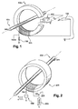
- the figure 2 also shows a primary conductor 202 in which circulates a current Iprim. This driver performs Nprim turns around the torus.
- Nprim is worth 1
- This winding has a number Nsec of turns (usually around a thousand).
- the square signal voltage generator 204 supplies a square voltage Vosc which switches between the + E and -E voltages.
- the role of this generator is to alternately carry the magnetic material in saturation of + Bsat to -Bsat (the magnetic flux density deviation ⁇ B ) at a frequency Fosc.
- this average current Isec is extracted, which makes it possible to deduce the value of the current to be measured Iprim.
- the extraction is carried out by integrating the current Isec.
- the invention therefore relates to a current sensing device disclosed by claim 1.
- the device according to the invention is also characterized in that the magnetic core is of fine section, of the order of one micrometer.
- the device according to the invention is also characterized in that the number of turns of the primary winding is 1, that is to say that it is a simple wire passing through the magnetic core.
- the device according to the invention is also characterized in that the number of turns of the primary winding is strictly greater than 1.
- the device according to the invention is also characterized in that the number of turns of the secondary winding is of the order of a thousand.
- the device according to the invention is also characterized in that the extractor circuit is an integrator circuit whose inputs are for one the electrical ground, for the other the terminal of the secondary winding to which is connected the measuring resistance, the output of the integrator circuit being connected to the terminal of the measuring resistor which is not connected to the secondary winding.
- the extractor circuit is an integrator circuit whose inputs are for one the electrical ground, for the other the terminal of the secondary winding to which is connected the measuring resistance, the output of the integrator circuit being connected to the terminal of the measuring resistor which is not connected to the secondary winding.
- This conductor is a primary winding crossed by a current Iprim which must be measured.
- the core 301 has a micrometric section, a few tens of micrometers.
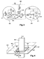
- the figure 4 illustrates such a torus.
- FIG 4 shows the conductor 302 which passes through a central orifice, a torus 401 mechanical square section. In practice this section could be other, circular or rectangular for example. Torus 401 is hollowed at its center by an opening 403.
- the torus 401 is formed of several elements.
- the torus 401 comprises a support 402 which is formed in a non-magnetic and electrically non-conductive substrate.
- the support 402 therefore has a crown section.
- the torus 401 finally comprises, wound around the core 404 a winding 406 of turns, corresponding to the secondary winding of the invention, also produced by a micrometric screen printing method of the type used to make the torus 404.
- winding 406 has two ends 407 and 408 to which the other elements of the sensor according to the invention are connected.
- the set of cores 402, 404, 405 and 406 is covered by a protective mold 409 such that said molding isolates the cores said cores leaving free the opening 403 and leaving accessible the ends 407 and 408 to be able to connect them other elements of the invention.
- the figure 3 shows that the end 407 is connected to an oscillator circuit 303 and that the end 408 is connected to an integrator circuit 304.
- the input 306 is connected to an electrical ground 311 via a resistor R1.
- the input 306 is connected to the output 310 via a resistor R2.
- Input 307 is directly connected to end 408.
- Input 308 is connected to a potential + E ..
- Input 309 is connected to a potential -E.
- the output 310 is connected to the end 407.
- the input 313 is connected to the electrical ground 311.
- the input 314 is connected to the end 408 via a resistor Rint.
- the input 314 is connected to the output 315 via a capacitor Cint.
- the output 315 is connected to the end 408 via a resistor Rsense, which is the measurement resistor.
- the circuit 303 is an autonomous voltage oscillator. It is a comparator whose 307 inverting and 306 non-inverting inputs oscillate between E and -E. The positive reaction of the system is ensured by the loopback of the output on the non-inverting input by a gain G ⁇ 1. It is recalled here that in the case of this arrangement the gain G is R1 / (R1 + R2).
- the voltage oscillator is a comparator whose output voltage can vary between + E and -E.
- This voltage circulates a current Isec in the winding 406.
- This current leads to saturation of the magnetic core.
- the voltage Vsec increases until reaching the voltage E ⁇ R ⁇ 1 R ⁇ 1 + R ⁇ 2 or - E ⁇ R ⁇ 1 R ⁇ 1 + R ⁇ 2 depending on the case.
- the comparator switches and the saturation goes in the opposite direction as illustrated by the figure 5 which shows that Vosc is a square voltage of frequency Fosc.
- the figure 5 also illustrates the voltage Vsec according to the evolution of Vosc.
- the voltage Vsec follows, with a deformation due to the magnetic core, the voltage Vosc.
- the voltage Vosc has a zero average value, except during a current variation in the conductor 302. In this case the voltage Vsec is disturbed and then restored to its stable form following the action of the integrator circuit 304.
- the circuit 304 is a looped system consisting of a comparator and an "integrator" gain function K i which makes it possible to extract the image from the average value of the Iprim current, ie the potential Vint.
- This voltage is fed back to Rsense, which makes it possible to control the oscillation at the center of the hysteresis cycle by compensating for the imbalance created by the ampere-turns of the primary current.
- the gain Ki is 1 / (Rint * Cint).
- Diagrams 502 and 503 of the figure 5 show the effect of an Istep current step on Vsec.
- the average value changes, until the compensation loop reacts and re-centers (T1) the average value of Vsec on volts by injecting a voltage Vint.
- the measurement of Vint thus makes it possible to know Iprim and thus to obtain the magnitude allowing the control of a device.
- the sensor according to the invention makes it possible to achieve higher accuracies than the other measurement methods.
- the accuracy of the measurement is essentially related to the accuracy of the Rsense resistance. It is a low power resistor, which can be easily found in accuracies of the order of 0.1%, and with a low sensitivity to temperature conditions.
- ampere turns make it possible to extract and to measure with a null error.
- the ampere turns are compensated directly and not an image of these through an intermediate sensor which induces an error.
- the dynamics of the sensor is related to the speed of the hysteresis cycle.
- the law of faraday imposes an effective section of the toroid of a few tens of micrometers. This is made possible thanks to a screen printed magnetic circuit. We can then obtain a bandwidth> 100Khz.
- the transformer effect guarantees good linearity.
- the integrator ensures that there is no offset effect near the current zero.
- the sensor according to the invention therefore has all the desired benefits.
Landscapes
- Engineering & Computer Science (AREA)
- Power Engineering (AREA)
- Physics & Mathematics (AREA)
- General Physics & Mathematics (AREA)
- Measuring Instrument Details And Bridges, And Automatic Balancing Devices (AREA)
- Measuring Magnetic Variables (AREA)
- Investigating Or Analyzing Materials By The Use Of Electric Means (AREA)
- Secondary Cells (AREA)
- Ignition Installations For Internal Combustion Engines (AREA)
- Level Indicators Using A Float (AREA)
- Measurement Of Current Or Voltage (AREA)
- Transformers For Measuring Instruments (AREA)
Applications Claiming Priority (2)
| Application Number | Priority Date | Filing Date | Title |
|---|---|---|---|
| FR0756599A FR2919068B1 (fr) | 2007-07-19 | 2007-07-19 | Capteur de courant perfectionne |
| PCT/FR2008/051298 WO2009024692A1 (fr) | 2007-07-19 | 2008-07-10 | Capteur de courant perfectionné |
Publications (2)
| Publication Number | Publication Date |
|---|---|
| EP2171483A1 EP2171483A1 (fr) | 2010-04-07 |
| EP2171483B1 true EP2171483B1 (fr) | 2011-01-12 |
Family
ID=39304821
Family Applications (1)
| Application Number | Title | Priority Date | Filing Date |
|---|---|---|---|
| EP08827954A Active EP2171483B1 (fr) | 2007-07-19 | 2008-07-10 | Capteur de courant perfectionné |
Country Status (11)
| Country | Link |
|---|---|
| US (1) | US8773112B2 (https=) |
| EP (1) | EP2171483B1 (https=) |
| JP (1) | JP2010533856A (https=) |
| CN (1) | CN101796421A (https=) |
| AT (1) | ATE495453T1 (https=) |
| BR (1) | BRPI0814264A2 (https=) |
| CA (1) | CA2707102C (https=) |
| DE (1) | DE602008004535D1 (https=) |
| FR (1) | FR2919068B1 (https=) |
| RU (1) | RU2431851C1 (https=) |
| WO (1) | WO2009024692A1 (https=) |
Families Citing this family (13)
| Publication number | Priority date | Publication date | Assignee | Title |
|---|---|---|---|---|
| EP2284549A1 (en) * | 2009-08-11 | 2011-02-16 | Liaisons Electroniques-Mècaniques LEM S.A. | Mixed mode fluxgate current transducer |
| IES20100604A2 (en) * | 2010-09-21 | 2011-06-08 | Shakira Ltd | DC & AC current detection circuit |
| FR2983966A1 (fr) * | 2011-12-12 | 2013-06-14 | Univ Orleans | Dispositif pour mesurer un courant electrique |
| FR2987515B1 (fr) * | 2012-02-29 | 2015-01-23 | Valeo Sys Controle Moteur Sas | Dispositif de detection d'un courant de fuite comprenant une composante continue, embarque dans un vehicule, et applications dudit dispositif |
| CN102749503A (zh) * | 2012-07-27 | 2012-10-24 | 成都生辉电子科技有限公司 | 工业大电流智能检测装置 |
| FR2997507B1 (fr) * | 2012-10-29 | 2014-11-28 | Labinal | Systeme et procede de surveillance d'un reseau maille de retour de courant d'un aeronef |
| DE102012021364A1 (de) * | 2012-11-02 | 2014-05-08 | SIEVA d.o.o. - poslovna enota Idrija | Gerät zur isolierten Messung von Strom und Verfahren zur isolierten Ermittlung von Strom |
| CN106501591A (zh) * | 2016-10-26 | 2017-03-15 | 绵阳市维博电子有限责任公司 | 一种基于道岔电流检测的开启式测量装置 |
| JP6544338B2 (ja) * | 2016-11-01 | 2019-07-17 | トヨタ自動車株式会社 | 電流センサ |
| RU169461U1 (ru) * | 2016-11-21 | 2017-03-21 | Акционерное общество "Научно-производственное объединение измерительной техники" | Дифференциальный измеритель постоянного тока |
| RU2664880C1 (ru) * | 2017-10-25 | 2018-08-23 | Федеральное государственное автономное образовательное учреждение высшего образования "Национальный исследовательский университет "Московский институт электронной техники" | Следящий преобразователь тока компенсационного типа |
| CN108572329B (zh) * | 2018-04-09 | 2020-03-24 | 陕西航空电气有限责任公司 | 并联馈线电源系统的电流采样装置及故障判断方法 |
| CN113933576B (zh) * | 2021-10-14 | 2023-11-10 | 北京理工大学 | 电子安全系统放电回路的非介入式电流测试方法 |
Family Cites Families (16)
| Publication number | Priority date | Publication date | Assignee | Title |
|---|---|---|---|---|
| SU617732A1 (ru) * | 1976-08-09 | 1978-07-30 | Предприятие П/Я Г-4485 | Датчик переменного тока низкой частоты |
| DE2920484A1 (de) * | 1979-05-21 | 1980-12-04 | Bosch Gmbh Robert | Messeinrichtung mit magnetischem kreis zum messen eines gleichstroms |
| US4529931A (en) * | 1983-04-07 | 1985-07-16 | Ford Motor Company | Single-coil current measuring circuit |
| JPS61155862A (ja) * | 1984-12-28 | 1986-07-15 | Mitsui Petrochem Ind Ltd | 変流装置 |
| JPH0757064B2 (ja) * | 1988-02-23 | 1995-06-14 | 三菱電機株式会社 | 漏電電流トランスデューサ |
| JPH01308004A (ja) * | 1988-06-07 | 1989-12-12 | Fuji Electric Co Ltd | 電流検出装置 |
| JP2816175B2 (ja) * | 1989-04-28 | 1998-10-27 | 三菱電機株式会社 | 直流電流測定装置 |
| US5223789A (en) * | 1989-06-23 | 1993-06-29 | Fuji Electric Co., Ltd. | AC/DC current detecting method |
| JPH03218475A (ja) * | 1989-11-06 | 1991-09-26 | Nkk Corp | 電流計測方法及びその装置 |
| JPH03216559A (ja) * | 1990-01-22 | 1991-09-24 | Fujitsu Ltd | 電流検出器 |
| JPH0464068A (ja) * | 1990-07-02 | 1992-02-28 | Fuji Electric Co Ltd | 直流電流検出方法 |
| DE19642472A1 (de) * | 1996-10-15 | 1998-04-16 | Abb Research Ltd | Flußkompensierter Stromsensor |
| DE19919602A1 (de) * | 1999-04-29 | 2000-11-30 | Vacuumschmelze Gmbh | Stromsensor nach dem Kompensationsprinzip |
| US6828786B2 (en) * | 2002-01-18 | 2004-12-07 | California Institute Of Technology | Method and apparatus for nanomagnetic manipulation and sensing |
| US20060192550A1 (en) * | 2005-02-25 | 2006-08-31 | Sandquist David A | Current sensor with magnetic toroid single frequency detection scheme |
| US7145321B2 (en) * | 2005-02-25 | 2006-12-05 | Sandquist David A | Current sensor with magnetic toroid |
-
2007
- 2007-07-19 FR FR0756599A patent/FR2919068B1/fr not_active Expired - Fee Related
-
2008
- 2008-07-10 BR BRPI0814264-5A2A patent/BRPI0814264A2/pt not_active IP Right Cessation
- 2008-07-10 RU RU2010105843/28A patent/RU2431851C1/ru not_active IP Right Cessation
- 2008-07-10 DE DE602008004535T patent/DE602008004535D1/de active Active
- 2008-07-10 JP JP2010516554A patent/JP2010533856A/ja active Pending
- 2008-07-10 CN CN200880105466A patent/CN101796421A/zh active Pending
- 2008-07-10 US US12/669,560 patent/US8773112B2/en active Active
- 2008-07-10 AT AT08827954T patent/ATE495453T1/de not_active IP Right Cessation
- 2008-07-10 EP EP08827954A patent/EP2171483B1/fr active Active
- 2008-07-10 WO PCT/FR2008/051298 patent/WO2009024692A1/fr not_active Ceased
- 2008-07-10 CA CA2707102A patent/CA2707102C/fr not_active Expired - Fee Related
Also Published As
| Publication number | Publication date |
|---|---|
| EP2171483A1 (fr) | 2010-04-07 |
| US20110101963A1 (en) | 2011-05-05 |
| CA2707102A1 (fr) | 2009-02-26 |
| US8773112B2 (en) | 2014-07-08 |
| BRPI0814264A2 (pt) | 2015-02-03 |
| JP2010533856A (ja) | 2010-10-28 |
| FR2919068B1 (fr) | 2009-09-18 |
| RU2431851C1 (ru) | 2011-10-20 |
| WO2009024692A1 (fr) | 2009-02-26 |
| DE602008004535D1 (de) | 2011-02-24 |
| CN101796421A (zh) | 2010-08-04 |
| CA2707102C (fr) | 2013-06-25 |
| FR2919068A1 (fr) | 2009-01-23 |
| ATE495453T1 (de) | 2011-01-15 |
Similar Documents
| Publication | Publication Date | Title |
|---|---|---|
| EP2171483B1 (fr) | Capteur de courant perfectionné | |
| EP1977258B1 (fr) | Dispositif de mesure de courant continu a forte dynamique de mesure, ensemble electrotechnique comportant un tel dispositif de mesure et dispositif de coupure ayant un tel ensemble electrotechnique | |
| EP3555642B1 (fr) | Capteur de courant a vanne de flux | |
| JP2010533856A5 (https=) | ||
| EP0499589A1 (fr) | Dispositif de mesure de courants | |
| EP2089724A2 (fr) | Compteur d'energie electrique comprenant au moins un capteur de mesure de courant de type inductif, et capteur associe | |
| CA1097765A (fr) | Procede de mesure de la position d'une tige magnetique, particulierement d'une barre de reglage d'un reacteur nucleaire | |
| EP0099784A1 (fr) | Déclencheur électronique analogique pour disjoncteur de protection contre les surintensités d'un réseau à courant alternatif | |
| WO2016207508A1 (fr) | Appareil pour mesurer un champ magnetique | |
| FR3002036A1 (fr) | Mesure de la temperature homogene d'un bobinage par augmentation de la resistance d'un fil | |
| EP2761309A1 (fr) | Capteur de courant sans contact | |
| JP2022506673A (ja) | タイミングに敏感な回路のための磁界パルス電流検知 | |
| EP2830215B1 (fr) | Preamplificateur de charge | |
| FR2694408A1 (fr) | Dispositif détecteur de défauts sur un réseau de distribution d'énergie électrique aérien. | |
| FR2989171A1 (fr) | Procede et dispositif de mesure d'un champ magnetique et de la temperature d'un transducteur magneto-resistif | |
| EP0324292A1 (fr) | Magnétomètre vectoriel continu à capteur capacitif magnétostrictif et gradientmètre comportant application de ce capteur | |
| EP1936389B1 (fr) | Capteur inductif de mesure de courant | |
| EP0074297B2 (fr) | Capteur de courant hybride compensé | |
| FR2752059A1 (fr) | Dispositif de mesure d'un courant circulant dans un conducteur | |
| FR2790313A1 (fr) | Capteur inductif sans contact pour la mesure de deplacements rectilignes ou angulaires | |
| EP4450983B1 (fr) | Procédé de mesure et ohmmètre de boucle mono-tore à compensation de flux de fuite dc | |
| EP2494695B1 (fr) | Systeme et procede de commande d'un capteur numerique | |
| FR2963432A1 (fr) | Capteur integre de mesure de tension ou de courant a base de magnetoresistances | |
| FR2831258A1 (fr) | Procede et dispositif de mesure magnetique de la position et de l'orientation d'un objet mobile par rapport a une structure fixe | |
| FR2719379A1 (fr) | Procédé de mesure permettant d'obtenir de manière isolée des échantillons d'un courant de forte intensité circulant dans un fil électrique. |
Legal Events
| Date | Code | Title | Description |
|---|---|---|---|
| PUAI | Public reference made under article 153(3) epc to a published international application that has entered the european phase |
Free format text: ORIGINAL CODE: 0009012 |
|
| 17P | Request for examination filed |
Effective date: 20100115 |
|
| AK | Designated contracting states |
Kind code of ref document: A1 Designated state(s): AT BE BG CH CY CZ DE DK EE ES FI FR GB GR HR HU IE IS IT LI LT LU LV MC MT NL NO PL PT RO SE SI SK TR |
|
| AX | Request for extension of the european patent |
Extension state: AL BA MK RS |
|
| 17Q | First examination report despatched |
Effective date: 20100517 |
|
| GRAP | Despatch of communication of intention to grant a patent |
Free format text: ORIGINAL CODE: EPIDOSNIGR1 |
|
| DAX | Request for extension of the european patent (deleted) | ||
| GRAS | Grant fee paid |
Free format text: ORIGINAL CODE: EPIDOSNIGR3 |
|
| GRAA | (expected) grant |
Free format text: ORIGINAL CODE: 0009210 |
|
| AK | Designated contracting states |
Kind code of ref document: B1 Designated state(s): AT BE BG CH CY CZ DE DK EE ES FI FR GB GR HR HU IE IS IT LI LT LU LV MC MT NL NO PL PT RO SE SI SK TR |
|
| REG | Reference to a national code |
Ref country code: GB Ref legal event code: FG4D Free format text: NOT ENGLISH |
|
| REG | Reference to a national code |
Ref country code: CH Ref legal event code: EP |
|
| REG | Reference to a national code |
Ref country code: IE Ref legal event code: FG4D Free format text: LANGUAGE OF EP DOCUMENT: FRENCH |
|
| REF | Corresponds to: |
Ref document number: 602008004535 Country of ref document: DE Date of ref document: 20110224 Kind code of ref document: P |
|
| REG | Reference to a national code |
Ref country code: DE Ref legal event code: R096 Ref document number: 602008004535 Country of ref document: DE Effective date: 20110224 |
|
| REG | Reference to a national code |
Ref country code: NL Ref legal event code: VDEP Effective date: 20110112 |
|
| LTIE | Lt: invalidation of european patent or patent extension |
Effective date: 20110112 |
|
| PG25 | Lapsed in a contracting state [announced via postgrant information from national office to epo] |
Ref country code: PT Free format text: LAPSE BECAUSE OF FAILURE TO SUBMIT A TRANSLATION OF THE DESCRIPTION OR TO PAY THE FEE WITHIN THE PRESCRIBED TIME-LIMIT Effective date: 20110512 Ref country code: ES Free format text: LAPSE BECAUSE OF FAILURE TO SUBMIT A TRANSLATION OF THE DESCRIPTION OR TO PAY THE FEE WITHIN THE PRESCRIBED TIME-LIMIT Effective date: 20110423 Ref country code: NO Free format text: LAPSE BECAUSE OF FAILURE TO SUBMIT A TRANSLATION OF THE DESCRIPTION OR TO PAY THE FEE WITHIN THE PRESCRIBED TIME-LIMIT Effective date: 20110412 Ref country code: LV Free format text: LAPSE BECAUSE OF FAILURE TO SUBMIT A TRANSLATION OF THE DESCRIPTION OR TO PAY THE FEE WITHIN THE PRESCRIBED TIME-LIMIT Effective date: 20110112 Ref country code: SE Free format text: LAPSE BECAUSE OF FAILURE TO SUBMIT A TRANSLATION OF THE DESCRIPTION OR TO PAY THE FEE WITHIN THE PRESCRIBED TIME-LIMIT Effective date: 20110112 Ref country code: LT Free format text: LAPSE BECAUSE OF FAILURE TO SUBMIT A TRANSLATION OF THE DESCRIPTION OR TO PAY THE FEE WITHIN THE PRESCRIBED TIME-LIMIT Effective date: 20110112 Ref country code: IS Free format text: LAPSE BECAUSE OF FAILURE TO SUBMIT A TRANSLATION OF THE DESCRIPTION OR TO PAY THE FEE WITHIN THE PRESCRIBED TIME-LIMIT Effective date: 20110512 Ref country code: HR Free format text: LAPSE BECAUSE OF FAILURE TO SUBMIT A TRANSLATION OF THE DESCRIPTION OR TO PAY THE FEE WITHIN THE PRESCRIBED TIME-LIMIT Effective date: 20110112 |
|
| REG | Reference to a national code |
Ref country code: IE Ref legal event code: FD4D |
|
| PG25 | Lapsed in a contracting state [announced via postgrant information from national office to epo] |
Ref country code: FI Free format text: LAPSE BECAUSE OF FAILURE TO SUBMIT A TRANSLATION OF THE DESCRIPTION OR TO PAY THE FEE WITHIN THE PRESCRIBED TIME-LIMIT Effective date: 20110112 Ref country code: BG Free format text: LAPSE BECAUSE OF FAILURE TO SUBMIT A TRANSLATION OF THE DESCRIPTION OR TO PAY THE FEE WITHIN THE PRESCRIBED TIME-LIMIT Effective date: 20110412 Ref country code: NL Free format text: LAPSE BECAUSE OF FAILURE TO SUBMIT A TRANSLATION OF THE DESCRIPTION OR TO PAY THE FEE WITHIN THE PRESCRIBED TIME-LIMIT Effective date: 20110112 Ref country code: CY Free format text: LAPSE BECAUSE OF FAILURE TO SUBMIT A TRANSLATION OF THE DESCRIPTION OR TO PAY THE FEE WITHIN THE PRESCRIBED TIME-LIMIT Effective date: 20110112 Ref country code: PL Free format text: LAPSE BECAUSE OF FAILURE TO SUBMIT A TRANSLATION OF THE DESCRIPTION OR TO PAY THE FEE WITHIN THE PRESCRIBED TIME-LIMIT Effective date: 20110112 Ref country code: SI Free format text: LAPSE BECAUSE OF FAILURE TO SUBMIT A TRANSLATION OF THE DESCRIPTION OR TO PAY THE FEE WITHIN THE PRESCRIBED TIME-LIMIT Effective date: 20110112 Ref country code: AT Free format text: LAPSE BECAUSE OF FAILURE TO SUBMIT A TRANSLATION OF THE DESCRIPTION OR TO PAY THE FEE WITHIN THE PRESCRIBED TIME-LIMIT Effective date: 20110112 |
|
| PG25 | Lapsed in a contracting state [announced via postgrant information from national office to epo] |
Ref country code: DK Free format text: LAPSE BECAUSE OF FAILURE TO SUBMIT A TRANSLATION OF THE DESCRIPTION OR TO PAY THE FEE WITHIN THE PRESCRIBED TIME-LIMIT Effective date: 20110112 Ref country code: EE Free format text: LAPSE BECAUSE OF FAILURE TO SUBMIT A TRANSLATION OF THE DESCRIPTION OR TO PAY THE FEE WITHIN THE PRESCRIBED TIME-LIMIT Effective date: 20110112 Ref country code: IE Free format text: LAPSE BECAUSE OF FAILURE TO SUBMIT A TRANSLATION OF THE DESCRIPTION OR TO PAY THE FEE WITHIN THE PRESCRIBED TIME-LIMIT Effective date: 20110112 |
|
| PLBE | No opposition filed within time limit |
Free format text: ORIGINAL CODE: 0009261 |
|
| STAA | Information on the status of an ep patent application or granted ep patent |
Free format text: STATUS: NO OPPOSITION FILED WITHIN TIME LIMIT |
|
| PG25 | Lapsed in a contracting state [announced via postgrant information from national office to epo] |
Ref country code: SK Free format text: LAPSE BECAUSE OF FAILURE TO SUBMIT A TRANSLATION OF THE DESCRIPTION OR TO PAY THE FEE WITHIN THE PRESCRIBED TIME-LIMIT Effective date: 20110112 Ref country code: RO Free format text: LAPSE BECAUSE OF FAILURE TO SUBMIT A TRANSLATION OF THE DESCRIPTION OR TO PAY THE FEE WITHIN THE PRESCRIBED TIME-LIMIT Effective date: 20110112 Ref country code: CZ Free format text: LAPSE BECAUSE OF FAILURE TO SUBMIT A TRANSLATION OF THE DESCRIPTION OR TO PAY THE FEE WITHIN THE PRESCRIBED TIME-LIMIT Effective date: 20110112 |
|
| 26N | No opposition filed |
Effective date: 20111013 |
|
| PG25 | Lapsed in a contracting state [announced via postgrant information from national office to epo] |
Ref country code: MT Free format text: LAPSE BECAUSE OF FAILURE TO SUBMIT A TRANSLATION OF THE DESCRIPTION OR TO PAY THE FEE WITHIN THE PRESCRIBED TIME-LIMIT Effective date: 20110112 |
|
| BERE | Be: lapsed |
Owner name: AIRBUS OPERATIONS (S.A.S) Effective date: 20110731 |
|
| REG | Reference to a national code |
Ref country code: DE Ref legal event code: R097 Ref document number: 602008004535 Country of ref document: DE Effective date: 20111013 |
|
| PG25 | Lapsed in a contracting state [announced via postgrant information from national office to epo] |
Ref country code: MC Free format text: LAPSE BECAUSE OF NON-PAYMENT OF DUE FEES Effective date: 20110731 |
|
| PG25 | Lapsed in a contracting state [announced via postgrant information from national office to epo] |
Ref country code: BE Free format text: LAPSE BECAUSE OF NON-PAYMENT OF DUE FEES Effective date: 20110731 |
|
| REG | Reference to a national code |
Ref country code: CH Ref legal event code: PL |
|
| PG25 | Lapsed in a contracting state [announced via postgrant information from national office to epo] |
Ref country code: LI Free format text: LAPSE BECAUSE OF NON-PAYMENT OF DUE FEES Effective date: 20120731 Ref country code: CH Free format text: LAPSE BECAUSE OF NON-PAYMENT OF DUE FEES Effective date: 20120731 |
|
| PG25 | Lapsed in a contracting state [announced via postgrant information from national office to epo] |
Ref country code: LU Free format text: LAPSE BECAUSE OF NON-PAYMENT OF DUE FEES Effective date: 20110710 |
|
| PG25 | Lapsed in a contracting state [announced via postgrant information from national office to epo] |
Ref country code: TR Free format text: LAPSE BECAUSE OF FAILURE TO SUBMIT A TRANSLATION OF THE DESCRIPTION OR TO PAY THE FEE WITHIN THE PRESCRIBED TIME-LIMIT Effective date: 20110112 |
|
| PG25 | Lapsed in a contracting state [announced via postgrant information from national office to epo] |
Ref country code: HU Free format text: LAPSE BECAUSE OF FAILURE TO SUBMIT A TRANSLATION OF THE DESCRIPTION OR TO PAY THE FEE WITHIN THE PRESCRIBED TIME-LIMIT Effective date: 20110112 |
|
| PG25 | Lapsed in a contracting state [announced via postgrant information from national office to epo] |
Ref country code: GR Free format text: LAPSE BECAUSE OF FAILURE TO SUBMIT A TRANSLATION OF THE DESCRIPTION OR TO PAY THE FEE WITHIN THE PRESCRIBED TIME-LIMIT Effective date: 20110112 |
|
| REG | Reference to a national code |
Ref country code: FR Ref legal event code: PLFP Year of fee payment: 9 |
|
| REG | Reference to a national code |
Ref country code: FR Ref legal event code: PLFP Year of fee payment: 10 |
|
| REG | Reference to a national code |
Ref country code: FR Ref legal event code: PLFP Year of fee payment: 11 |
|
| PGFP | Annual fee paid to national office [announced via postgrant information from national office to epo] |
Ref country code: DE Payment date: 20190719 Year of fee payment: 12 |
|
| REG | Reference to a national code |
Ref country code: DE Ref legal event code: R119 Ref document number: 602008004535 Country of ref document: DE |
|
| PG25 | Lapsed in a contracting state [announced via postgrant information from national office to epo] |
Ref country code: DE Free format text: LAPSE BECAUSE OF NON-PAYMENT OF DUE FEES Effective date: 20210202 |
|
| PGFP | Annual fee paid to national office [announced via postgrant information from national office to epo] |
Ref country code: IT Payment date: 20220726 Year of fee payment: 15 |
|
| PG25 | Lapsed in a contracting state [announced via postgrant information from national office to epo] |
Ref country code: IT Free format text: LAPSE BECAUSE OF NON-PAYMENT OF DUE FEES Effective date: 20230710 |
|
| PGFP | Annual fee paid to national office [announced via postgrant information from national office to epo] |
Ref country code: GB Payment date: 20250722 Year of fee payment: 18 |
|
| PGFP | Annual fee paid to national office [announced via postgrant information from national office to epo] |
Ref country code: FR Payment date: 20250724 Year of fee payment: 18 |