EP2170545B1 - Portable cutter - Google Patents
Portable cutter Download PDFInfo
- Publication number
- EP2170545B1 EP2170545B1 EP20080791579 EP08791579A EP2170545B1 EP 2170545 B1 EP2170545 B1 EP 2170545B1 EP 20080791579 EP20080791579 EP 20080791579 EP 08791579 A EP08791579 A EP 08791579A EP 2170545 B1 EP2170545 B1 EP 2170545B1
- Authority
- EP
- European Patent Office
- Prior art keywords
- workpiece
- dust
- guide
- dust collection
- main body
- Prior art date
- Legal status (The legal status is an assumption and is not a legal conclusion. Google has not performed a legal analysis and makes no representation as to the accuracy of the status listed.)
- Active
Links
- 239000000428 dust Substances 0.000 claims abstract description 120
- 238000005520 cutting process Methods 0.000 claims abstract description 59
- 229910052751 metal Inorganic materials 0.000 description 3
- 239000002184 metal Substances 0.000 description 3
- 239000013013 elastic material Substances 0.000 description 2
- 229920005989 resin Polymers 0.000 description 2
- 239000011347 resin Substances 0.000 description 2
- 239000002390 adhesive tape Substances 0.000 description 1
- 229910052782 aluminium Inorganic materials 0.000 description 1
- XAGFODPZIPBFFR-UHFFFAOYSA-N aluminium Chemical compound [Al] XAGFODPZIPBFFR-UHFFFAOYSA-N 0.000 description 1
- 238000005452 bending Methods 0.000 description 1
- 229920001971 elastomer Polymers 0.000 description 1
- 230000014509 gene expression Effects 0.000 description 1
- 239000000463 material Substances 0.000 description 1
- 238000000034 method Methods 0.000 description 1
- 230000002093 peripheral effect Effects 0.000 description 1
- 229920000515 polycarbonate Polymers 0.000 description 1
- 239000004417 polycarbonate Substances 0.000 description 1
- 230000001681 protective effect Effects 0.000 description 1
- 238000007493 shaping process Methods 0.000 description 1
- 229920002803 thermoplastic polyurethane Polymers 0.000 description 1
- 229920005992 thermoplastic resin Polymers 0.000 description 1
Images


Classifications
-
- B—PERFORMING OPERATIONS; TRANSPORTING
- B23—MACHINE TOOLS; METAL-WORKING NOT OTHERWISE PROVIDED FOR
- B23D—PLANING; SLOTTING; SHEARING; BROACHING; SAWING; FILING; SCRAPING; LIKE OPERATIONS FOR WORKING METAL BY REMOVING MATERIAL, NOT OTHERWISE PROVIDED FOR
- B23D59/00—Accessories specially designed for sawing machines or sawing devices
- B23D59/006—Accessories specially designed for sawing machines or sawing devices for removing or collecting chips
-
- B—PERFORMING OPERATIONS; TRANSPORTING
- B23—MACHINE TOOLS; METAL-WORKING NOT OTHERWISE PROVIDED FOR
- B23D—PLANING; SLOTTING; SHEARING; BROACHING; SAWING; FILING; SCRAPING; LIKE OPERATIONS FOR WORKING METAL BY REMOVING MATERIAL, NOT OTHERWISE PROVIDED FOR
- B23D45/00—Sawing machines or sawing devices with circular saw blades or with friction saw discs
- B23D45/16—Hand-held sawing devices with circular saw blades
-
- B—PERFORMING OPERATIONS; TRANSPORTING
- B27—WORKING OR PRESERVING WOOD OR SIMILAR MATERIAL; NAILING OR STAPLING MACHINES IN GENERAL
- B27B—SAWS FOR WOOD OR SIMILAR MATERIAL; COMPONENTS OR ACCESSORIES THEREFOR
- B27B9/00—Portable power-driven circular saws for manual operation
- B27B9/02—Arrangements for adjusting the cutting depth or the amount of tilting
-
- B—PERFORMING OPERATIONS; TRANSPORTING
- B27—WORKING OR PRESERVING WOOD OR SIMILAR MATERIAL; NAILING OR STAPLING MACHINES IN GENERAL
- B27G—ACCESSORY MACHINES OR APPARATUS FOR WORKING WOOD OR SIMILAR MATERIALS; TOOLS FOR WORKING WOOD OR SIMILAR MATERIALS; SAFETY DEVICES FOR WOOD WORKING MACHINES OR TOOLS
- B27G19/00—Safety guards or devices specially adapted for wood saws; Auxiliary devices facilitating proper operation of wood saws
- B27G19/02—Safety guards or devices specially adapted for wood saws; Auxiliary devices facilitating proper operation of wood saws for circular saws
- B27G19/04—Safety guards or devices specially adapted for wood saws; Auxiliary devices facilitating proper operation of wood saws for circular saws for manually-operated power-driven circular saws
-
- B—PERFORMING OPERATIONS; TRANSPORTING
- B28—WORKING CEMENT, CLAY, OR STONE
- B28D—WORKING STONE OR STONE-LIKE MATERIALS
- B28D7/00—Accessories specially adapted for use with machines or devices of the preceding groups
- B28D7/02—Accessories specially adapted for use with machines or devices of the preceding groups for removing or laying dust, e.g. by spraying liquids; for cooling work
Definitions
- the present invention relates to a portable cutter having a dust collection cover for collecting dust generated from a workpiece.
- a portable cutter according to the preamble of claim 1 is known from US 6 269 543 .
- the electric cutter for cutting a concrete block and a tile has been well-known.
- the electric cutter has a drive unit such as an electric motor or an engine, a circular saw blade coupled to the shaft of the motor or engine, and a protection cover surrounding the outer periphery of the circular saw blade to prevent dust from scattering.
- a drive unit such as an electric motor or an engine
- a circular saw blade coupled to the shaft of the motor or engine
- a protection cover surrounding the outer periphery of the circular saw blade to prevent dust from scattering.
- Japanese Patent Application Publication No. 2002- 046018 discloses an electric cutter that has a dust collecting hose attached to a protection cover of a main body.
- the dust-collecting hose is connected to an electric dust collector.
- the electric dust collector draws and collects the dust generated during the cutting operation.
- Japanese Patent Application Publication No. 2004- 058388 discloses a cutter having a base for moving on a workpiece while cutting operation, and a coil spring interposed between the base and a wheel cover. The coil spring urging the wheel cover away from the base, so that the cutter can collect the dust generated from the workpiece effectively.
- the scattering direction of the dust may change as the cutting depth by the blade. Therefore, it is difficult to collect all dust only by the wheel cover.
- the dust generated by the cutting operation generally scatters almost parallel to the surface of the workpiece.
- the dust collides with the wheel cover at almost right angles to the inner surface of the wheel cover, the dust is guided into the inlet port of the wheel cover.
- the larger the diameter of the blade the faster the dust scatters from the blade in the tangential direction of the blade. If the scattering speed of the dust is higher, the dust may not be guided into the inlet port of the wheel cover after the dust collides with the inner surface of the wheel cover.
- the sides of the wheel cover are required to be covered with another cover.
- the entire blade would be covered, so that the user can hardly look at a cutting-start position or a cutting-end position.
- the user has to make a mark on a line of the workpiece extending from the peripheral surface of the base or the wheel cover, and aligning the cutting line with the mark, thereby confirming the position of the blade.
- it is difficult for the user to cut the workpiece at any desired position with high accuracy.
- the wheel cover may have an observation window in one side.
- the user may lift the base from the workpiece to confirm the position of the blade. In either case, the scattered dust still leaks through the observation window or the gap between the base and the workpiece to outside, which lowers the dust collecting efficiency.
- An object of the present invention is to provide a portable cutter in which dust can be efficiently guided into the inlet port of the dust collection cover, regardless of a cutting depth to which the blade cuts into the workpiece.
- the problem is solved by a portable cutter according to claim 1.
- the present invention features a portable cutter having a base member, a main body, a cutting blade, a protection member, a dust collection member, and a guide member.
- the base member moves on a workpiece, the base member having a shaft provided in proximity to one end thereof.
- the main body is coupled to the base member. A posture of the main body with respect to the base member is changeable.
- the cutting blade is attached to the main body and driven to cut the workpiece.
- the cutting blade has an outer periphery.
- the protection member covers a part of the outer periphery of the cutting blade.
- the dust collection member has an inlet provided in proximity to the outer periphery of the cutting blade for drawing and collecting dust.
- the guide member is pivotably supported to the shaft of the base member for guiding the dust to the opening of the dust collection member.
- the guide member for guiding dust into the inlet port of the dust collection cover is rotatably provided to the shaft of the base unit.
- the urging means pivotably moves the guide member about the shaft to urge the guide member to the workpiece. Therefore, the guide member keeps contacting an upper surface of the workpiece even when the posture of the base unit with respect to the main body is changed to change the cutting depth.
- the guide member can therefore smoothly guide the dust into the inlet of the dust collection member, preventing the dust flying in the tangential direction of the blade from leaking out of the protection member.
- the dust from the workpiece can be collected at higher efficiency without excessively covering the periphery of the blade.
- the above structure enables a user to visually confirm the how the workpiece is being cut at the start and end of a cutting process as well as during the cutting process.
- the guide member has a guide wall portion directed to the opening of the dust collection member.
- the guide wall portion has a lower end and two side ends. Therefore, the dust is smoothly guided into the inlet of the dust collection member with the guide wall portion. This structure helps to collect the dust at a higher efficiency.
- the guide member further includes two side wall portions coupled to the side ends of the guide wall portion, respectively, each side wall portion having a lower end.
- the guide member is configured to contact the lower ends of the side wall portions and the lower end of the guide wall portion simultaneously with the workpiece when the one end of the base is contact with the workpiece for cutting.
- the base unit is inclined to the workpiece at the start of the cutting process and abuts one end of the base unit on the workpiece.
- the lower ends of the side wall portions and the lower end of the guide wall portion simultaneously contact with the workpiece.
- the guide member surrounds a cutting point of the workpiece by the cutting blade without any gap between he side wall portions and the guide wall portion of the guide member and the workpiece so that the dust generated from the workpiece is prevent from scattering out of the protection cover and the dust collection member. That is, the guide member smoothly guides all dust into the inlet of the dust collection cover. The dust is therefore reliably collected.
- the lower end of the guide wall portion is kept contact with the workpiece when the guide member is positioned above the lower surface. Therefore, when a lower surface of the base unit contacts with the workpiece, the lower end of the guide wall portion is kept contact with the workpiece, so that no gap develops between the guide member and the workpiece. Hence, the dust can be efficiently guided by the guide member into the inlet of the dust collection cover without leaking out of the dust collection member. The dust is thus reliably collected.
- the dust collection member is made from an elastic member.
- the workpiece is not damaged, even if the dust collection cover collides with the workpiece.
- the guide member is positioned inside of the opening of the dust collection member. Accordingly, the dust from the workpiece can be reliably guided to the inlet of the dust collection member, even if the dust collection cover becomes deformed.
- an electric portable cutter 1 has a main body 2, a circular saw blade 3, a protection cover 4, a base unit 8, and a dust collection cover 12.
- the circular saw blade 3 is attached to the right-front part of the main body 2 and can be rotated.
- the protection cover 4 protects the circular saw blade 3.
- the base unit 8 is used to adjust a cutting depth to which a workpiece is cut with the circular saw blade 3.
- the dust collection cover 12 is attached to the protection cover 4.
- the main body 2 incorporates an electric motor (not shown) that is used as a drive unit. As shown in Fig. 3 , the center of the circular saw blade 3 is secured to a rotating shaft 5 of the electric motor.
- the main body 2 has a handle unit 2a at the rear part.
- the handle unit 2a holds a switch 6 which turns on or off the electric motor when operated.
- a power cord 7 is connected to the handle unit 2a to supply power to the electric motor.
- a sub-handle 17 is provided on the front portion of the main body 2 and located on the left side of the blade 3.
- the sub-handle 17 is formed by bending and shaping a pipe like a rectangular frame as viewed from the front.
- a user can hold the handle unit 2a and the sub-handle 17 at the same time. The user can therefore hold the electric cutter 1 steadfast and stably set the circular saw blade 3 to the workpiece W.
- the protection cover 4 includes a first protection cover 4A ( FIG. 1 ), a second protection cover 4B, and a third protection cover 4C ( FIG. 2 ).
- the first protection cover 4A is attached to the main body 2, covering the outer periphery of the circular saw blade 3 and a part of one side thereof.
- the second protection cover 4B is fastened to first protection cover 4A, covering a part of the other side of the blade 3.
- the third protection cover 4C is fastened to the base unit 8 to cover the other side of the circular saw blade 3 together with the second protection cover 4B.
- the first protection cover 4A is made from a hard material such as aluminum.
- the second protection cover 4B and the third protection cover 4C are made of resin such as polycarbonate.
- the base unit 8 is composed of a rectangular frame 8' made of metal and surrounding the circular saw blade 3.
- a shaft 9 couples the front-end portions of the opposing longer sides of the base unit 8 (see FIG. 1 ).
- the ends of the shaft 9 are rotatably coupled to a pair of connecting members 10 made of metal, respectively. More precisely, one end of the shaft 9 is coupled to one end of one connecting member 10, and the other end of the shaft 9 is coupled to one end of the other connecting member 10. Further, the other end of one connecting member 10 is movably coupled to the first protection cover 4A with a knob bolt 21, and the other end of the other connecting member 10 is movably coupled to the second protection cover 4B with the knob bolt 21.
- the posture of the base unit 8 with respect to the main body 2 can be changed. If the posture of the base unit 8 with respect to the main body 2 is changed, the length of the circular saw blade 3 projecting from the base unit 8 can be changed. In other words, the cutting depth of the circular saw blade 3 can be adjusted.
- the base unit 8 has the function of adjusting the cutting depth to which the circular saw blade 3 can cut the workpiece, and the function of moving the blade 3 on the workpiece W in a stable state. Therefore, the base unit 8 has two pairs of rollers 22 at the front end and the rear end in order to move smoothly on the workpiece W.
- the base unit 8 has a front guide 8A close to the front end and a rear guide 8B close to the rear end.
- the front guide 8A is rotatably coupled to the shaft 9.
- the front guide 8A will be described later in detail.
- the rear guide 8B extends to intersect almost at right angles to the plane including the frame 8' of the base unit 8.
- the rear guide 8B is shaped like a channel, surrounding the circular saw blade 3 from both sides.
- the rear guide 8B has the side faces, each having an arch-shaped guide groove 8b.
- An adjuster 11 is inserted in both guide grooves 8b and threadly engaged to any desired position of the main body 2. When the adjuster 11 is fastened, the rear guide 8B is secured to the main body 2.
- the position of the base unit 8 with respect to the main body 2 can be changed by changing the position of the adjuster 11 with respect to the guide groove 8b.
- the cutting depth to which the circular saw blade 3 cuts the workpiece W can be adjusted.
- the third protection cover 4C is fastened to the base unit 8 to straddle the front end of the rear guide 8B and the frame 8' of the base unit 8.
- the dust collection cover 12 is attached to the first protection cover 4A to extend along the periphery of the first protection cover 4A.
- the dust collection cover 12 is shaped like a tube.
- the dust collection cover 12 has two opening ends, and is made of elastic material such as rubber, soft urethane resin, and thermoplastic resin. As shown in FIGS. 4 and 5 , the space inside the dust collection cover 12 defines a dust passage 13.
- One opening end of the dust collection cover 12 is a inlet port 12a that opens to the outer periphery of the circular saw blade 3.
- the other opening end of the dust collection cover 12 is an outlet port 12b.
- An adapter 14 made from resin has one end connected to the outlet port 12b by a band 19 that is made of metal.
- the other end of the adapter 14 is inserted into the hose cap 16 attached to one end of a hose 15.
- the other end of the hose 15 is connected to a dust collector (not shown).
- one end of the dust collection cover 12 located near the inlet port 12a is fastened to the top of one connecting member 10 by the knob bolt 21.
- the other end of the dust collection cover 12, which lies near the outlet port 12b is fastened to the second protection cover 4B together with the band 19 by screws 20.
- the dust collection cover 12 has an extension portion 12c that has a thin thickness and extends downwards.
- the extension portion 12c overlaps the outer surface of the first protection cover 4A. If the back surface of the extension portion 12c is secured to one side of the first protection cover 4A with a double-sided adhesive tape, the extension portion 12c does not remove from the side surface of the first protection cover 4A to hinder the cutting of the workpiece W. This is desirable in view of safety.
- a plurality of grooves 12d is made in the entire surface of the dust collection cover 12.
- the grooves 12d intersect with one another and extend from front to rear, from left to right, and up and down.
- a plurality of grooves 4a are made in the side surface of the second protection cover 4B and are connected to the grooves 12d made in the dust collection cover 12.
- the front guide 8A is a member having a cross section shaped like U.
- the front guide 8A has a boss 8d and a projection 8a.
- the shaft 9 extends through the boss 8d.
- the projection 8a extends forwards from the boss 8d.
- the front guide 8A has a guide wall portion 8e and two sidewall portions 8h and 8h.
- the guide wall portion 8e is configured to be directed to the inlet port 12a of the dust collection cover 12.
- the guide wall portion 8e has a rectangular shape with a lower side end 8ee.
- the sidewalls portions 8h and 8h are shaped like a fan and coupled to the side ends of the guide wall surface 8e, respectively.
- the sidewall portion 8h has a prescribed thickness and has two contact portions 8f and 8g at the lower end.
- the contact portions 8f and 8g are continuous to each other. As shown in FIG.
- the contact portion 8f is a portion that linearly comes to contact the workpiece W together with the lower side end 8ee of the guide wall portion 8e when the circular saw blade 3 starts cutting the workpiece W.
- the contact portion 8f is configured that the line L extending from the contact portion 8f passes a contact point P, the front end of the base unit 8, where the base unit 8 contacts the workpiece W.
- the lower side end 8ee and the contact portions 8f of the front guide 8A contact the surface of the workpiece W to surround the cutting portion of the workpiece W without providing any gap between the workpiece W and the lower side end 8ee and the contact portions 8f of the front guide 8A.
- the contact portion 8g comes to contact with the workpiece W when the front guide 8A rotates upwards with respect to the base unit 8. At this time, the contact portion 8g of the front guide 8A becomes parallel to the frame 8' of the base unit 8. Further, the lower side end 8ee of the front guide 8A is still contact with the workpiece W. On the other hand, a part of the side wall portion 8h of the front guide 8A is positioned inside of the protection cover 4C. That is, the cutting portion of the workpiece W is surrounded by the front guide 8A without providing any gap between the lower side end 8ee of the front guide 8A and the workpiece W.
- the sidewall portions 8h, 8h slide on the inner surfaces of the dust collection cover 12 when the front guide 8A rotates upwards about the shaft 9. No gap is provided between the sidewall portion 8h and the dust collection cover 12.
- the user To cut the work piece W by using the electric cutter 1, the user first inclines the main body 2 to the workpiece W and pushes the front end of the base unit 8 on the mark P provided on the workpiece W. At this point, the front guide 8A is biased by the spring 18 about the shaft 9, with the contact portion 8f being set in line contact with the upper surface of the workpiece W. Holding both the handle 2a and sub-handle 17, which are provided on the main body 2, the user turns the switch 6 on. The electric motor is then activated. The rotation of the motor is transmitted to the drive shaft 5 of the electric cutter 1, so that the circular saw blade 3 is rotated in the direction of arrow a (counterclockwise direction) as shown in FIG. 12 . The user then pivotably moves the main body 2 about the mark P, cutting the workpiece. As a result, the base unit 8 is positioned on the workpiece W, as shown in FIG. 12 .
- the cutting depth H1 to which the blade 3 has cut the workpiece W is relatively larger.
- the cutting depth can be adjusted to H2 (H2 ⁇ H1) if the user first loosens the adjuster 11 to move the main body 2 upwards with respect to the base unit 8 and then tightens the adjuster 11, fixing the main body 2 to the base unit 8, as shown in FIG. 15 .
- the first protection cover 4A and the second protection cover 4B certainly move up together with the main body 2, but the third protection cover 4C remains secured to the base unit 8. Therefore, the sides of the circular saw blade 3, positioned above the base unit 8, remain covered with the second and third protection covers 4B and 4C, respectively.
- the front guide 8A is biased by the spring 18, rotated about the shaft 9 and pushed to the workpiece W. Therefore, the front guide 8A always contacts the upper surface of the workpiece W even if the position of the main body 2 to the base unit 8 is changed.
- the spring 18 biases the front guide 8A at all times, the front guide 8A is kept in contact with the workpiece W to be cut.
- the guide wall portion 8e and the sidewall portions 8h cover the upper surface of the workpiece W and the inlet port 12a of the dust collection cover 12 without providing any gap between the upper surface of the workpiece W, and the guide wall and the sidewall portions 8e, 8h.
- This structure prevents the dust from scattering from the protection cover 4 and the dust collection cover 12. Since the dust is prevented from scattering outside the protection cover 4, the work environment can be improved.
- the front guide 8A that guides the dust into the inlet port 12a of the dust collection cover 12 can be pivotably movable with respect to the base unit 8, and remain in contact with the workpiece W by virtue of the bias of the spring 18. Therefore, the guide 8A always contacts the surface of the workpiece W even if the cutting depth to which the circular saw blade 3 cuts the workpiece W is changed. Hence, no gap develops between the front guide 8A and the surface of the workpiece W.
- the front guide 8A efficiently guides the dust flying from the circular saw blade 3 in the tangential direction thereof smoothly into the inlet port 12a of the dust collection cover 12. As a result, the dust can be collected at high efficiency without using any other cover that covers the entire circular saw blade 3.
- the user can visually confirm the starting and end points of the workpiece and how the workpiece W is being cut at the start and end of cutting process, as well as during the cutting process. This process helps to enhance the work efficiency.
- the dust is smoothly guided into the inlet port 12a of the dust collection cover 12, while moving at a small angle relative to the workpiece W along the guide wall portion 8e of the front guide 8A. This movement of the dust can achieve a high dust-collecting efficiency.
- the main body 2 is set on the workpiece W and inclined to the workpiece W, while aligning the front end of the base unit 8 with the mark P on the workpiece W (see FIG. 11 ) at the start of the cutting process.
- the contact portion 8f of the front guide 8A which first contacts the workpiece W is configured to contact a predetermined area of the upper surface of the workpiece W.
- the contact portion 8f contacts the surface of the workpiece W at the start of the cutting process.
- This structure prevents a gap from developing between the upper surface of the workpiece W and the front guide 8A, and ultimately prevents the dust from leaking outside of the dust collection cover 12. That is, the front guide 8A smoothly guides all dust into the inlet port 12a of the dust collection cover 12.
- the contact portion 8g of the front guide 8A extends parallel to the lower surface of the base unit 8, because the front guide 8A is positioned above the base unit 8, as illustrated in FIG. 13 .
- This structure develops no gap between the front guide 8A and the workpiece W.
- the front guide 8A can efficiently guide the dust into the inlet port 12a of the dust collection cover 12, so that the dust is efficiently collected.
- the dust collection cover 12 is made from the elastic material, the user will not be injured even if he or she hits their hands against the dust collection cover 12 while holding the main body 2.
- the workpiece W is not damaged, even if the dust collection cover 12 collides with the workpiece W.
- the circular saw blade 3 is pushed onto the workpiece W as shown in FIGS. 16 and 17 , the user usually holds the part of the sub-handle 17 which is close to the blade 3.
- the extension portion 12c overlaps the first protection cover 4A and prevents the user's fingers X holding the sub-handle 17 from pushing against the first protection cover 4A.
- the front guide 8A is arranged inside the inlet port 12a of the dust collection cover 12 as shown in FIG. 10 .
- the front guide 8A can therefore reliably prevent the dust collection cover 12 from contacting the circular saw blade 3 when the dust collection cover 12 is deformed. The cutting process can therefore proceed in safety.
- the present invention has been described, with reference to an embodiment applied to an electric cutter.
- the invention is not limited to an electric cutter.
- the invention is applicable to any types of a portable cutter, such as a disk saw, a disk grinder, which achieves the same advantages as described above.
Landscapes
- Engineering & Computer Science (AREA)
- Mechanical Engineering (AREA)
- Life Sciences & Earth Sciences (AREA)
- Wood Science & Technology (AREA)
- Forests & Forestry (AREA)
- Sawing (AREA)
- Processing Of Stones Or Stones Resemblance Materials (AREA)
- Crushing And Pulverization Processes (AREA)
Abstract
Description
- The present invention relates to a portable cutter having a dust collection cover for collecting dust generated from a workpiece. A portable cutter according to the preamble of
claim 1 is known fromUS 6 269 543 . - An Electric cutter for cutting a concrete block and a tile has been well-known. The electric cutter has a drive unit such as an electric motor or an engine, a circular saw blade coupled to the shaft of the motor or engine, and a protection cover surrounding the outer periphery of the circular saw blade to prevent dust from scattering. When cutting is performed with such an electric cutter, it is difficult to prevent dust from scattering. Even if a workpiece is cut a little by the cutter, the generated dust may inevitably lower visibility at the working site. Therefore, a user is required to wear a dust-free mask and/or protective goggles whenever using the electric cutter.
- Japanese Patent Application Publication No.
2002- 046018 - Japanese Patent Application Publication No.
2004- 058388 - With the conventional cutters, the scattering direction of the dust may change as the cutting depth by the blade. Therefore, it is difficult to collect all dust only by the wheel cover. For example, the dust generated by the cutting operation generally scatters almost parallel to the surface of the workpiece. When the dust collides with the wheel cover at almost right angles to the inner surface of the wheel cover, the dust is guided into the inlet port of the wheel cover. Thus, the larger the diameter of the blade, the faster the dust scatters from the blade in the tangential direction of the blade. If the scattering speed of the dust is higher, the dust may not be guided into the inlet port of the wheel cover after the dust collides with the inner surface of the wheel cover.
- To solve the problem mentioned above, the sides of the wheel cover are required to be covered with another cover. When the sides of the wheel cover are covered with another cover, the entire blade would be covered, so that the user can hardly look at a cutting-start position or a cutting-end position. The user has to make a mark on a line of the workpiece extending from the peripheral surface of the base or the wheel cover, and aligning the cutting line with the mark, thereby confirming the position of the blade. Thus, it is difficult for the user to cut the workpiece at any desired position with high accuracy.
- To enable the user to place the blade at any position precisely, the wheel cover may have an observation window in one side. Alternatively, the user may lift the base from the workpiece to confirm the position of the blade. In either case, the scattered dust still leaks through the observation window or the gap between the base and the workpiece to outside, which lowers the dust collecting efficiency.
- An object of the present invention is to provide a portable cutter in which dust can be efficiently guided into the inlet port of the dust collection cover, regardless of a cutting depth to which the blade cuts into the workpiece. The problem is solved by a portable cutter according to
claim 1. - The present invention features a portable cutter having a base member, a main body, a cutting blade, a protection member, a dust collection member, and a guide member. The base member moves on a workpiece, the base member having a shaft provided in proximity to one end thereof. The main body is coupled to the base member. A posture of the main body with respect to the base member is changeable. The cutting blade is attached to the main body and driven to cut the workpiece. The cutting blade has an outer periphery. The protection member covers a part of the outer periphery of the cutting blade. The dust collection member has an inlet provided in proximity to the outer periphery of the cutting blade for drawing and collecting dust. The guide member is pivotably supported to the shaft of the base member for guiding the dust to the opening of the dust collection member.
- According to the present invention, the guide member for guiding dust into the inlet port of the dust collection cover is rotatably provided to the shaft of the base unit. Preferably, the urging means pivotably moves the guide member about the shaft to urge the guide member to the workpiece. Therefore, the guide member keeps contacting an upper surface of the workpiece even when the posture of the base unit with respect to the main body is changed to change the cutting depth. The guide member can therefore smoothly guide the dust into the inlet of the dust collection member, preventing the dust flying in the tangential direction of the blade from leaking out of the protection member. Thus, the dust from the workpiece can be collected at higher efficiency without excessively covering the periphery of the blade. The above structure enables a user to visually confirm the how the workpiece is being cut at the start and end of a cutting process as well as during the cutting process.
- Preferably, the guide member has a guide wall portion directed to the opening of the dust collection member. The guide wall portion has a lower end and two side ends. Therefore, the dust is smoothly guided into the inlet of the dust collection member with the guide wall portion. This structure helps to collect the dust at a higher efficiency.
- Preferably, the guide member further includes two side wall portions coupled to the side ends of the guide wall portion, respectively, each side wall portion having a lower end. The guide member is configured to contact the lower ends of the side wall portions and the lower end of the guide wall portion simultaneously with the workpiece when the one end of the base is contact with the workpiece for cutting.
- Accordingly, the base unit is inclined to the workpiece at the start of the cutting process and abuts one end of the base unit on the workpiece. At this time, the lower ends of the side wall portions and the lower end of the guide wall portion simultaneously contact with the workpiece. Thus, the guide member surrounds a cutting point of the workpiece by the cutting blade without any gap between he side wall portions and the guide wall portion of the guide member and the workpiece so that the dust generated from the workpiece is prevent from scattering out of the protection cover and the dust collection member. That is, the guide member smoothly guides all dust into the inlet of the dust collection cover. The dust is therefore reliably collected.
- Preferably, the lower end of the guide wall portion is kept contact with the workpiece when the guide member is positioned above the lower surface. Therefore, when a lower surface of the base unit contacts with the workpiece, the lower end of the guide wall portion is kept contact with the workpiece, so that no gap develops between the guide member and the workpiece. Hence, the dust can be efficiently guided by the guide member into the inlet of the dust collection cover without leaking out of the dust collection member. The dust is thus reliably collected.
- Preferably, the dust collection member is made from an elastic member. The workpiece is not damaged, even if the dust collection cover collides with the workpiece.
- Preferably, the guide member is positioned inside of the opening of the dust collection member. Accordingly, the dust from the workpiece can be reliably guided to the inlet of the dust collection member, even if the dust collection cover becomes deformed.
- The particular features and advantages of the invention as well as other objects will become apparent from the following description taken in connection with the accompanying drawings, in which:
-
FIG. 1 is a perspective view of an electric cutter according to the present invention; -
FIG. 2 is a side view of the electric cutter shown inFIG. 1 ; -
FIG. 3 is a front view of the electric cutter shown inFIG. 1 ; -
FIG. 4 is a sectional view taken along lines of A-A shown inFIG. 2 ; -
FIG. 5 is a sectional view taken along lines of B-B shown inFIG. 2 ; -
FIG. 6 is a partial sectional view showing a front edge of the base unit and a front guide; -
FIG. 7 is a side view of the front guide; -
FIG. 8 is a perspective view of the front guide, as seen from the font; -
FIG. 9 is a perspective view of the front guide, as seen from the rear; -
FIG. 10 is a perspective view illustrating the positional relation between the dust collection cover and the front guide; -
FIG. 11 is a partially sectional view illustrating the positional relation between the base unit and the front guide on the workpiece when the electric cutter starts cutting the workpiece; -
FIG. 12 is a partially sectional view showing the electric cutter cutting a workpiece at a deeper depth; -
FIG. 13 is a partially sectional view illustrating the positional relation between the base unit and the front guide when the electric cutter cuts a workpiece at a shallower depth; -
FIG. 14 is a side view showing the electric cutter cutting the workpiece at the deeper depth; -
FIG. 15 is a side view showing the electric cutter cutting the workpiece at the shallower depth; -
FIG. 16 is a side view showing electric cutter cutting the workpiece at the deeper depth; and -
FIG. 17 is a sectional view taken along lines of E-E shown inFIG. 16 . -
- 1
- portable cutter
- 2
- main body
- 3
- cutting blade
- 4
- protection cover
- 5
- drive shaft
- 8
- base unit
- 8A
- guide member
- 12
- inlet port
- A portable cutter according to an embodiment of the present invention will be described with reference to the accompanying drawings. The expressions "front", "rear", "above", "below", "left", and "right" are used throughout the description to define the various parts when the portable cutter is disposed in an orientation in which it is intended to be used.
- As shown in
FIG. 1 , an electricportable cutter 1 has amain body 2, acircular saw blade 3, aprotection cover 4, abase unit 8, and adust collection cover 12. Thecircular saw blade 3 is attached to the right-front part of themain body 2 and can be rotated. Theprotection cover 4 protects thecircular saw blade 3. Thebase unit 8 is used to adjust a cutting depth to which a workpiece is cut with thecircular saw blade 3. Thedust collection cover 12 is attached to theprotection cover 4. - The
main body 2 incorporates an electric motor (not shown) that is used as a drive unit. As shown inFig. 3 , the center of thecircular saw blade 3 is secured to arotating shaft 5 of the electric motor. Themain body 2 has ahandle unit 2a at the rear part. Thehandle unit 2a holds aswitch 6 which turns on or off the electric motor when operated. Apower cord 7 is connected to thehandle unit 2a to supply power to the electric motor. - A sub-handle 17 is provided on the front portion of the
main body 2 and located on the left side of theblade 3. The sub-handle 17 is formed by bending and shaping a pipe like a rectangular frame as viewed from the front. A user can hold thehandle unit 2a and the sub-handle 17 at the same time. The user can therefore hold theelectric cutter 1 steadfast and stably set thecircular saw blade 3 to the workpiece W. - The
protection cover 4 includes afirst protection cover 4A (FIG. 1 ), asecond protection cover 4B, and athird protection cover 4C (FIG. 2 ). Thefirst protection cover 4A is attached to themain body 2, covering the outer periphery of thecircular saw blade 3 and a part of one side thereof. Thesecond protection cover 4B is fastened tofirst protection cover 4A, covering a part of the other side of theblade 3. Thethird protection cover 4C is fastened to thebase unit 8 to cover the other side of thecircular saw blade 3 together with thesecond protection cover 4B. Thefirst protection cover 4A is made from a hard material such as aluminum. Thesecond protection cover 4B and thethird protection cover 4C are made of resin such as polycarbonate. - The
base unit 8 is composed of a rectangular frame 8' made of metal and surrounding thecircular saw blade 3. Ashaft 9 couples the front-end portions of the opposing longer sides of the base unit 8 (seeFIG. 1 ). The ends of theshaft 9 are rotatably coupled to a pair of connectingmembers 10 made of metal, respectively. More precisely, one end of theshaft 9 is coupled to one end of one connectingmember 10, and the other end of theshaft 9 is coupled to one end of the other connectingmember 10. Further, the other end of one connectingmember 10 is movably coupled to thefirst protection cover 4A with aknob bolt 21, and the other end of the other connectingmember 10 is movably coupled to thesecond protection cover 4B with theknob bolt 21. Hence, when the connectingmembers 10 are rotated about theshaft 9, the posture of thebase unit 8 with respect to themain body 2 can be changed. If the posture of thebase unit 8 with respect to themain body 2 is changed, the length of thecircular saw blade 3 projecting from thebase unit 8 can be changed. In other words, the cutting depth of thecircular saw blade 3 can be adjusted. - The
base unit 8 has the function of adjusting the cutting depth to which thecircular saw blade 3 can cut the workpiece, and the function of moving theblade 3 on the workpiece W in a stable state. Therefore, thebase unit 8 has two pairs ofrollers 22 at the front end and the rear end in order to move smoothly on the workpiece W. - As shown in
FIG. 2 , thebase unit 8 has afront guide 8A close to the front end and arear guide 8B close to the rear end. Thefront guide 8A is rotatably coupled to theshaft 9. Thefront guide 8A will be described later in detail. Therear guide 8B extends to intersect almost at right angles to the plane including the frame 8' of thebase unit 8. Therear guide 8B is shaped like a channel, surrounding thecircular saw blade 3 from both sides. Therear guide 8B has the side faces, each having an arch-shapedguide groove 8b. Anadjuster 11 is inserted in both guidegrooves 8b and threadly engaged to any desired position of themain body 2. When theadjuster 11 is fastened, therear guide 8B is secured to themain body 2. Therefore, the position of thebase unit 8 with respect to themain body 2 can be changed by changing the position of theadjuster 11 with respect to theguide groove 8b. Hence, the cutting depth to which thecircular saw blade 3 cuts the workpiece W can be adjusted. Note that thethird protection cover 4C is fastened to thebase unit 8 to straddle the front end of therear guide 8B and the frame 8' of thebase unit 8. - The
dust collection cover 12 is attached to thefirst protection cover 4A to extend along the periphery of thefirst protection cover 4A. Thedust collection cover 12 is shaped like a tube. Thedust collection cover 12 has two opening ends, and is made of elastic material such as rubber, soft urethane resin, and thermoplastic resin. As shown inFIGS. 4 and5 , the space inside thedust collection cover 12 defines adust passage 13. - One opening end of the
dust collection cover 12 is ainlet port 12a that opens to the outer periphery of thecircular saw blade 3. The other opening end of thedust collection cover 12 is anoutlet port 12b. Anadapter 14 made from resin has one end connected to theoutlet port 12b by aband 19 that is made of metal. The other end of theadapter 14 is inserted into thehose cap 16 attached to one end of ahose 15. The other end of thehose 15 is connected to a dust collector (not shown). - As shown in
FIG. 4 , one end of the dust collection cover 12 located near theinlet port 12a is fastened to the top of one connectingmember 10 by theknob bolt 21. As shown inFIG. 12 , the other end of thedust collection cover 12, which lies near theoutlet port 12b, is fastened to thesecond protection cover 4B together with theband 19 byscrews 20. - The
dust collection cover 12 has anextension portion 12c that has a thin thickness and extends downwards. Theextension portion 12c overlaps the outer surface of thefirst protection cover 4A. If the back surface of theextension portion 12c is secured to one side of thefirst protection cover 4A with a double-sided adhesive tape, theextension portion 12c does not remove from the side surface of thefirst protection cover 4A to hinder the cutting of the workpiece W. This is desirable in view of safety. - A plurality of
grooves 12d, each having a depth of about 0.5 mm, is made in the entire surface of thedust collection cover 12. Thegrooves 12d intersect with one another and extend from front to rear, from left to right, and up and down. As shown inFIG. 2 , a plurality ofgrooves 4a are made in the side surface of thesecond protection cover 4B and are connected to thegrooves 12d made in thedust collection cover 12. - The
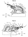
front guide 8A will now be described in detail. As shown inFIGS. 7, 8 and9 , thefront guide 8A is a member having a cross section shaped like U. Thefront guide 8A has aboss 8d and aprojection 8a. Theshaft 9 extends through theboss 8d. Theprojection 8a extends forwards from theboss 8d. Once thefront guide 8A is attached to theshaft 9 of thebase unit 8, theprojection 8a is biased upwards by aspring 18 interposed between the front end of thebase unit 8 and theprojection 8a, as shown inFIG. 6 . As a result, the rear portion of thefront guide 8A is rotated about theshaft 9 and biased downwards. When thefront guide 8A is attached to theshaft 9 of thebase unit 8, thefront guide 8A is positioned inside theinlet port 12a of thedust collection cover 12. - As shown in
FIGS. 8 and9 , thefront guide 8A has aguide wall portion 8e and twosidewall portions guide wall portion 8e is configured to be directed to theinlet port 12a of thedust collection cover 12. Theguide wall portion 8e has a rectangular shape with a lower side end 8ee. Thesidewalls portions guide wall surface 8e, respectively. Thesidewall portion 8h has a prescribed thickness and has twocontact portions contact portions FIG. 11 , thecontact portion 8f is a portion that linearly comes to contact the workpiece W together with the lower side end 8ee of theguide wall portion 8e when thecircular saw blade 3 starts cutting the workpiece W. Thecontact portion 8f is configured that the line L extending from thecontact portion 8f passes a contact point P, the front end of thebase unit 8, where thebase unit 8 contacts the workpiece W. Thus, the lower side end 8ee and thecontact portions 8f of thefront guide 8A contact the surface of the workpiece W to surround the cutting portion of the workpiece W without providing any gap between the workpiece W and the lower side end 8ee and thecontact portions 8f of thefront guide 8A. - Referring to
FIG. 13 , thecontact portion 8g comes to contact with the workpiece W when thefront guide 8A rotates upwards with respect to thebase unit 8. At this time, thecontact portion 8g of thefront guide 8A becomes parallel to the frame 8' of thebase unit 8. Further, the lower side end 8ee of thefront guide 8A is still contact with the workpiece W. On the other hand, a part of theside wall portion 8h of thefront guide 8A is positioned inside of theprotection cover 4C. That is, the cutting portion of the workpiece W is surrounded by thefront guide 8A without providing any gap between the lower side end 8ee of thefront guide 8A and the workpiece W. - The
sidewall portions dust collection cover 12 when thefront guide 8A rotates upwards about theshaft 9. No gap is provided between thesidewall portion 8h and thedust collection cover 12. - How to use the
electric cutter 1 to cut a groove in a workpiece W will be explained below. - To cut the work piece W by using the
electric cutter 1, the user first inclines themain body 2 to the workpiece W and pushes the front end of thebase unit 8 on the mark P provided on the workpiece W. At this point, thefront guide 8A is biased by thespring 18 about theshaft 9, with thecontact portion 8f being set in line contact with the upper surface of the workpiece W. Holding both thehandle 2a and sub-handle 17, which are provided on themain body 2, the user turns theswitch 6 on. The electric motor is then activated. The rotation of the motor is transmitted to thedrive shaft 5 of theelectric cutter 1, so that thecircular saw blade 3 is rotated in the direction of arrow a (counterclockwise direction) as shown inFIG. 12 . The user then pivotably moves themain body 2 about the mark P, cutting the workpiece. As a result, thebase unit 8 is positioned on the workpiece W, as shown inFIG. 12 . - In this state, when the user moves the
main body 2 in the cutting direction (the direction of arrow b), as shown inFIG. 14 , a groove having the depth H1 is cut in the workpiece W. - As shown in
FIG. 14 , the cutting depth H1 to which theblade 3 has cut the workpiece W is relatively larger. The cutting depth can be adjusted to H2 (H2 < H1) if the user first loosens theadjuster 11 to move themain body 2 upwards with respect to thebase unit 8 and then tightens theadjuster 11, fixing themain body 2 to thebase unit 8, as shown inFIG. 15 . At this time, thefirst protection cover 4A and thesecond protection cover 4B certainly move up together with themain body 2, but thethird protection cover 4C remains secured to thebase unit 8. Therefore, the sides of thecircular saw blade 3, positioned above thebase unit 8, remain covered with the second and third protection covers 4B and 4C, respectively. - On the other hand, the
front guide 8A is biased by thespring 18, rotated about theshaft 9 and pushed to the workpiece W. Therefore, thefront guide 8A always contacts the upper surface of the workpiece W even if the position of themain body 2 to thebase unit 8 is changed. - When the
blade 3 is rotated to cut the workpiece W, dust is generated. The dust is guided by thefront guide 8A of thebase unit 8 and is drawn into thedust passage 13 through theinlet port 12a of the dust-collectingcover 12, by virtue of the drawing force generated by the rotation of thecircular saw blade 3 and the dust collector. In thedust passage 13, the dust moves to theoutlet port 12b in the direction of arrow d. The dust is then drawn from theoutlet port 12b into the dust collector through theadapter 14 and thehose 15. The dust is thereby collected in the dust collector. - Further, since the
spring 18 biases thefront guide 8A at all times, thefront guide 8A is kept in contact with the workpiece W to be cut. Hence, theguide wall portion 8e and thesidewall portions 8h cover the upper surface of the workpiece W and theinlet port 12a of the dust collection cover 12 without providing any gap between the upper surface of the workpiece W, and the guide wall and thesidewall portions protection cover 4 and thedust collection cover 12. Since the dust is prevented from scattering outside theprotection cover 4, the work environment can be improved. - As described above, the
front guide 8A that guides the dust into theinlet port 12a of the dust collection cover 12 can be pivotably movable with respect to thebase unit 8, and remain in contact with the workpiece W by virtue of the bias of thespring 18. Therefore, theguide 8A always contacts the surface of the workpiece W even if the cutting depth to which thecircular saw blade 3 cuts the workpiece W is changed. Hence, no gap develops between thefront guide 8A and the surface of the workpiece W. Thefront guide 8A efficiently guides the dust flying from thecircular saw blade 3 in the tangential direction thereof smoothly into theinlet port 12a of thedust collection cover 12. As a result, the dust can be collected at high efficiency without using any other cover that covers the entirecircular saw blade 3. Moreover, the user can visually confirm the starting and end points of the workpiece and how the workpiece W is being cut at the start and end of cutting process, as well as during the cutting process. This process helps to enhance the work efficiency. - In the embodiment, the dust is smoothly guided into the
inlet port 12a of thedust collection cover 12, while moving at a small angle relative to the workpiece W along theguide wall portion 8e of thefront guide 8A. This movement of the dust can achieve a high dust-collecting efficiency. - As has been described, the
main body 2 is set on the workpiece W and inclined to the workpiece W, while aligning the front end of thebase unit 8 with the mark P on the workpiece W (seeFIG. 11 ) at the start of the cutting process. Thecontact portion 8f of thefront guide 8A which first contacts the workpiece W is configured to contact a predetermined area of the upper surface of the workpiece W. Thus, thecontact portion 8f contacts the surface of the workpiece W at the start of the cutting process. This structure prevents a gap from developing between the upper surface of the workpiece W and thefront guide 8A, and ultimately prevents the dust from leaking outside of thedust collection cover 12. That is, thefront guide 8A smoothly guides all dust into theinlet port 12a of thedust collection cover 12. - In addition, if the length of the
circular saw blade 3 projecting from thebase unit 8 becomes longer, this operation increases the cutting depth. In this case, thecontact portion 8g of thefront guide 8A extends parallel to the lower surface of thebase unit 8, because thefront guide 8A is positioned above thebase unit 8, as illustrated inFIG. 13 . This structure develops no gap between thefront guide 8A and the workpiece W. Thefront guide 8A can efficiently guide the dust into theinlet port 12a of thedust collection cover 12, so that the dust is efficiently collected. - Furthermore, since the
dust collection cover 12 is made from the elastic material, the user will not be injured even if he or she hits their hands against the dust collection cover 12 while holding themain body 2. The workpiece W is not damaged, even if thedust collection cover 12 collides with the workpiece W. When thecircular saw blade 3 is pushed onto the workpiece W as shown inFIGS. 16 and17 , the user usually holds the part of the sub-handle 17 which is close to theblade 3. In this case, theextension portion 12c overlaps thefirst protection cover 4A and prevents the user's fingers X holding the sub-handle 17 from pushing against thefirst protection cover 4A. - In the embodiment, the
front guide 8A is arranged inside theinlet port 12a of the dust collection cover 12 as shown inFIG. 10 . Thefront guide 8A can therefore reliably prevent the dust collection cover 12 from contacting thecircular saw blade 3 when thedust collection cover 12 is deformed. The cutting process can therefore proceed in safety. - The present invention has been described, with reference to an embodiment applied to an electric cutter. The invention is not limited to an electric cutter.
- The invention is applicable to any types of a portable cutter, such as a disk saw, a disk grinder, which achieves the same advantages as described above.
Claims (7)
- A portable cutter (1), comprising:a base member (8) that moves on a workpiece (W) , the base member having a shaft (9) provided in proximity to one end thereof;a main body (2) coupled to the base member, a posture of the main body with respect to the base member being changeable;a cutting blade (3) attached to the main body and driven to cut the workpiece, the cutting blade having an outer periphery, the cutting blade having a cutting width;a protection member (4) that covers a part of the outer periphery of the cutting blade;a dust collection member (12) having an opening (12a) provided in proximity to the outer periphery of the cutting blade for drawing and collecting dust; anda guide member (8A) pivotably supported to the shaft of the base member for guiding the dust to the opening of the dust collection member, and the guide member having a width which is wider than the cutting width of the cutting blade characterised in that the guide member is projectable toward the workpiece from the base member.
- The portable cutter as claimed in claim 1, further comprising urging means (18) for urging the guide member to the workpiece.
- The portable cutter as claimed in any one of claims 1-2, wherein the guide member comprises a guide wall portion (8e) directed to the opening of the dust collection member, the guide wall portion having a lower end and two side ends.
- The portable cutter as claimed in claim 3, wherein the guide member further comprises two side wall portions (8h, 8h) coupled to the side ends of the guide wall portion, respectively, each side wall portion having a lower end (8g or 8f),
the guide member is configured to contact the lower ends of the side wall portions and the lower end of the guide wall portion simultaneously with the workpiece when the one end of the base is contact with the workpiece for cutting. - The portable cutter as claimed in claim 3, wherein the lower end of the guide wall portion is kept contact with the workpiece when the guide member is positioned above the lower surface.
- The portable cutter as claimed in claim 1, wherein the dust collection member is made from an elastic member.
- The portable cutter as claimed in claim 6, wherein the guide member is positioned inside of the opening of the dust collection member.
Applications Claiming Priority (2)
| Application Number | Priority Date | Filing Date | Title |
|---|---|---|---|
| JP2007185201A JP5093464B2 (en) | 2007-07-17 | 2007-07-17 | Portable cutting machine |
| PCT/JP2008/063328 WO2009011454A1 (en) | 2007-07-17 | 2008-07-17 | Portable cutter |
Publications (2)
| Publication Number | Publication Date |
|---|---|
| EP2170545A1 EP2170545A1 (en) | 2010-04-07 |
| EP2170545B1 true EP2170545B1 (en) | 2011-04-13 |
Family
ID=39877757
Family Applications (1)
| Application Number | Title | Priority Date | Filing Date |
|---|---|---|---|
| EP20080791579 Active EP2170545B1 (en) | 2007-07-17 | 2008-07-17 | Portable cutter |
Country Status (7)
| Country | Link |
|---|---|
| US (1) | US9101993B2 (en) |
| EP (1) | EP2170545B1 (en) |
| JP (1) | JP5093464B2 (en) |
| CN (1) | CN101631637B (en) |
| AT (1) | ATE505283T1 (en) |
| DE (1) | DE602008006194D1 (en) |
| WO (1) | WO2009011454A1 (en) |
Cited By (3)
| Publication number | Priority date | Publication date | Assignee | Title |
|---|---|---|---|---|
| WO2012099509A1 (en) * | 2011-01-18 | 2012-07-26 | Husqvarna Ab | Cutting and dust or slurry collecting assembly and working machine |
| WO2012099522A1 (en) * | 2011-01-18 | 2012-07-26 | Husqvarna Ab | Cutting and dust or slurry collecting assembly and working machine |
| US11440220B2 (en) | 2018-11-28 | 2022-09-13 | Black & Decker, Inc. | Replacement of rotatable cutting discs of a power tool |
Families Citing this family (35)
| Publication number | Priority date | Publication date | Assignee | Title |
|---|---|---|---|---|
| US8393939B2 (en) * | 2009-03-31 | 2013-03-12 | Saint-Gobain Abrasives, Inc. | Dust collection for an abrasive tool |
| CN101987483B (en) * | 2009-08-04 | 2013-06-19 | 余深权 | Recovery mechanism for dust and waste residues of stones |
| JP5385164B2 (en) * | 2010-01-15 | 2014-01-08 | 株式会社マキタ | Cutting machine |
| DE102010048424A1 (en) * | 2010-07-31 | 2012-02-02 | Protool Gmbh | Guide device and thus equipped hand-machine tool |
| US20150113814A2 (en) * | 2010-08-18 | 2015-04-30 | Jacob Cuzdey | Convertible zero-clearance circular saw |
| JP5666964B2 (en) * | 2011-04-06 | 2015-02-12 | リョービ株式会社 | Cutting machine |
| JP5758792B2 (en) * | 2011-12-16 | 2015-08-05 | リョービ株式会社 | Circular saw |
| CN106378491A (en) * | 2012-07-13 | 2017-02-08 | 苏州宝时得电动工具有限公司 | Portable cutting machine |
| AU2013377995B2 (en) * | 2013-02-05 | 2017-02-02 | Husqvarna Ab | A liquid dispensing system |
| WO2014151826A1 (en) * | 2013-03-15 | 2014-09-25 | Robert Bosch Gmbh | Dust collection system for a circular saw |
| JP5891538B1 (en) * | 2015-06-17 | 2016-03-23 | 株式会社ナカヤ | Electric cutting machine with dust control function |
| JP6704787B2 (en) * | 2015-06-18 | 2020-06-03 | 株式会社マキタ | Cutting machine dust cover |
| US10173345B2 (en) | 2015-06-18 | 2019-01-08 | Makita Corporation | Dust collection cover for cutting devices |
| JP6431445B2 (en) * | 2015-06-18 | 2018-11-28 | 株式会社マキタ | Dust collecting cover of cutting machine |
| JP6431446B2 (en) * | 2015-06-18 | 2018-11-28 | 株式会社マキタ | Dust collecting cover of cutting machine |
| US9937638B2 (en) * | 2015-06-18 | 2018-04-10 | Makita Corporation | Dust collection cover for cutting devices |
| DE102015008579A1 (en) * | 2015-06-26 | 2016-12-29 | Maschinenfabrik Otto Baier Gmbh | Processing device, in particular in the form of a diamond wall chaser |
| KR101746938B1 (en) | 2015-09-03 | 2017-06-13 | 이중호 | Carrier attachable or detachable on cutting machine |
| JP6007457B1 (en) * | 2015-10-24 | 2016-10-12 | 株式会社ナカヤ | Electric cutting machine with dust control function |
| CN105945339A (en) * | 2016-05-01 | 2016-09-21 | 王本 | Handheld dust-free cutting machine |
| JP6847651B2 (en) * | 2016-09-01 | 2021-03-24 | 株式会社マキタ | Portable cutting machine |
| US10792836B2 (en) * | 2016-09-15 | 2020-10-06 | Nanjing Chervon Industry Co., Ltd. | Concrete cutter with depth setting and retention system |
| US10293421B2 (en) | 2016-09-15 | 2019-05-21 | Dustless Depot, Llc | Circular saw dust collection shroud |
| SE540907C2 (en) | 2016-11-03 | 2018-12-18 | Husqvarna Ab | A dust removal arrangement for an engine-driven tool |
| DE102017110981A1 (en) * | 2017-05-19 | 2018-11-22 | Homag Plattenaufteiltechnik Gmbh | Workpiece processing system and method for operating a workpiece processing system |
| US10875109B1 (en) | 2018-04-30 | 2020-12-29 | Kreg Enterprises, Inc. | Adaptive cutting system |
| USD908149S1 (en) | 2018-10-23 | 2021-01-19 | Dustless Depot Llc | Angle grinder dust shroud with variable position slots for mounting brackets |
| US11123839B2 (en) | 2018-10-23 | 2021-09-21 | Dustless Depot Llc | Grinder dust shroud with input shaft gasket and adjustable mounting mechanism |
| CN109333832A (en) * | 2018-12-27 | 2019-02-15 | 金陵科技学院 | A kind of building floor tile cutting auxiliary device |
| EP3705229A1 (en) * | 2019-03-04 | 2020-09-09 | Hilti Aktiengesellschaft | Dust hood extension device and system comprising such a dust hood extension device and an adapter |
| CN112123604A (en) * | 2019-03-07 | 2020-12-25 | 杭州曼京科技有限公司 | A ground fluting device for interior decoration |
| US11273505B2 (en) | 2019-03-27 | 2022-03-15 | Dustless Depot, Llc | Circular saw dust collection shroud |
| GB2588832B (en) * | 2019-11-11 | 2022-04-27 | Evolution Power Tools Ltd | A handheld power tool |
| IT202100017816A1 (en) * | 2021-07-06 | 2023-01-06 | Scm Group Spa | Machine tool for carrying out at least one machining by removal of material on a panel or other piece, equipped with an improved system for diverting the flow of waste material. |
| WO2023110446A1 (en) | 2021-12-16 | 2023-06-22 | Shl Medical Ag | Sub-assembly of a medicament delivery device |
Family Cites Families (13)
| Publication number | Priority date | Publication date | Assignee | Title |
|---|---|---|---|---|
| US2522006A (en) * | 1946-05-31 | 1950-09-12 | Alex B Wilcox | Power-driven cast cutter |
| US4150598A (en) * | 1977-12-12 | 1979-04-24 | Rockwell International Corporation | Radial arm saw guard |
| US4255995A (en) * | 1980-01-24 | 1981-03-17 | Connor J Franklin | Dust confining and collection housing for power table saws and the like |
| JPS61163802A (en) | 1985-01-14 | 1986-07-24 | 松下電工株式会社 | Circular saw device |
| JPH0647683Y2 (en) | 1987-08-21 | 1994-12-07 | 日立工機株式会社 | Portable dust collector Dust collecting mechanism |
| US5084972A (en) * | 1991-01-25 | 1992-02-04 | Waugh Ricky L | Device for collecting dust from a portable circular saw |
| US5537748A (en) * | 1991-07-09 | 1996-07-23 | Ryobi Limited | Cover structure for electric circular saw |
| US5327649A (en) * | 1993-02-11 | 1994-07-12 | Skinner Christopher L | Circular saw with dust collector |
| JPH10272622A (en) * | 1997-03-28 | 1998-10-13 | Meiwa Seisakusho:Kk | Hand cutter |
| JP2000037705A (en) * | 1998-07-24 | 2000-02-08 | Makita Corp | Structure for preventing cuttings from scattering in portable circular saw |
| JP4119601B2 (en) * | 2000-07-07 | 2008-07-16 | 日立工機株式会社 | Portable circular saw |
| US6543142B2 (en) * | 2001-03-21 | 2003-04-08 | Ray Floyd Bruce | Chip deflector for a circular saw |
| US7465328B2 (en) * | 2005-07-22 | 2008-12-16 | Black & Decker Inc. | Dust collector for a power tool |
-
2007
- 2007-07-17 JP JP2007185201A patent/JP5093464B2/en active Active
-
2008
- 2008-07-17 CN CN2008800079054A patent/CN101631637B/en active Active
- 2008-07-17 WO PCT/JP2008/063328 patent/WO2009011454A1/en active Application Filing
- 2008-07-17 DE DE200860006194 patent/DE602008006194D1/en active Active
- 2008-07-17 US US12/530,522 patent/US9101993B2/en active Active
- 2008-07-17 EP EP20080791579 patent/EP2170545B1/en active Active
- 2008-07-17 AT AT08791579T patent/ATE505283T1/en not_active IP Right Cessation
Cited By (5)
| Publication number | Priority date | Publication date | Assignee | Title |
|---|---|---|---|---|
| WO2012099509A1 (en) * | 2011-01-18 | 2012-07-26 | Husqvarna Ab | Cutting and dust or slurry collecting assembly and working machine |
| WO2012099522A1 (en) * | 2011-01-18 | 2012-07-26 | Husqvarna Ab | Cutting and dust or slurry collecting assembly and working machine |
| US9662800B2 (en) | 2011-01-18 | 2017-05-30 | Husqvarna Ab | Cutting and dust or slurry collecting assembly and working machine |
| US11919199B2 (en) | 2011-01-18 | 2024-03-05 | Husqvarna Ab | Cutting and dust or slurry collecting assembly and working machine |
| US11440220B2 (en) | 2018-11-28 | 2022-09-13 | Black & Decker, Inc. | Replacement of rotatable cutting discs of a power tool |
Also Published As
| Publication number | Publication date |
|---|---|
| WO2009011454A1 (en) | 2009-01-22 |
| ATE505283T1 (en) | 2011-04-15 |
| CN101631637B (en) | 2013-07-17 |
| JP5093464B2 (en) | 2012-12-12 |
| DE602008006194D1 (en) | 2011-05-26 |
| CN101631637A (en) | 2010-01-20 |
| WO2009011454A4 (en) | 2009-03-19 |
| JP2009023004A (en) | 2009-02-05 |
| US9101993B2 (en) | 2015-08-11 |
| EP2170545A1 (en) | 2010-04-07 |
| US20100043768A1 (en) | 2010-02-25 |
Similar Documents
| Publication | Publication Date | Title |
|---|---|---|
| EP2170545B1 (en) | Portable cutter | |
| CA2790967C (en) | Saw assembly with floating bearing for worm drive and motor shaft | |
| EP0810071A2 (en) | Viewing window for circular saw guard | |
| JP4957228B2 (en) | cutter | |
| US8567295B2 (en) | Band saw blade removal mechanism | |
| US6757982B2 (en) | Safety improvements for power tool | |
| CA2790966C (en) | Spring biased base with offset pivot point | |
| US9434015B2 (en) | Saw assembly with bevel gear drivetrain | |
| CA2790976C (en) | Lockout forward flip lever for power saw | |
| CN108907338B (en) | Electric circular saw | |
| JP5092567B2 (en) | Portable tools | |
| JP2011051333A (en) | Portable cutting tool and dust collection structure | |
| EP2929969B1 (en) | Saw assembly with bevel gear drivetrain | |
| JP5385164B2 (en) | Cutting machine | |
| JP2008188714A (en) | Cutting device for straight member | |
| US20090049699A1 (en) | Protective device for hand-held power tool | |
| CA2791316C (en) | Base with beveled lateral side surface | |
| US10071498B2 (en) | Power saw crown molding cutting guide | |
| EP2995408A1 (en) | Power circular saw | |
| US20130081528A1 (en) | Power Saw Miter Cutting Guide | |
| US20130081288A1 (en) | Pipe Deburring Accessory for Circular Saw | |
| JP2001062806A (en) | Portable dust-collecting circular saw | |
| JP2008188713A (en) | Cutting device for straight member | |
| JPH0462841B2 (en) |
Legal Events
| Date | Code | Title | Description |
|---|---|---|---|
| PUAI | Public reference made under article 153(3) epc to a published international application that has entered the european phase |
Free format text: ORIGINAL CODE: 0009012 |
|
| 17P | Request for examination filed |
Effective date: 20100211 |
|
| AK | Designated contracting states |
Kind code of ref document: A1 Designated state(s): AT BE BG CH CY CZ DE DK EE ES FI FR GB GR HR HU IE IS IT LI LT LU LV MC MT NL NO PL PT RO SE SI SK TR |
|
| AX | Request for extension of the european patent |
Extension state: AL BA MK RS |
|
| GRAP | Despatch of communication of intention to grant a patent |
Free format text: ORIGINAL CODE: EPIDOSNIGR1 |
|
| DAX | Request for extension of the european patent (deleted) | ||
| GRAS | Grant fee paid |
Free format text: ORIGINAL CODE: EPIDOSNIGR3 |
|
| GRAA | (expected) grant |
Free format text: ORIGINAL CODE: 0009210 |
|
| AK | Designated contracting states |
Kind code of ref document: B1 Designated state(s): AT BE BG CH CY CZ DE DK EE ES FI FR GB GR HR HU IE IS IT LI LT LU LV MC MT NL NO PL PT RO SE SI SK TR |
|
| REG | Reference to a national code |
Ref country code: GB Ref legal event code: FG4D |
|
| REG | Reference to a national code |
Ref country code: CH Ref legal event code: EP |
|
| REG | Reference to a national code |
Ref country code: IE Ref legal event code: FG4D |
|
| REF | Corresponds to: |
Ref document number: 602008006194 Country of ref document: DE Date of ref document: 20110526 Kind code of ref document: P |
|
| REG | Reference to a national code |
Ref country code: DE Ref legal event code: R096 Ref document number: 602008006194 Country of ref document: DE Effective date: 20110526 |
|
| REG | Reference to a national code |
Ref country code: NL Ref legal event code: VDEP Effective date: 20110413 |
|
| LTIE | Lt: invalidation of european patent or patent extension |
Effective date: 20110413 |
|
| PG25 | Lapsed in a contracting state [announced via postgrant information from national office to epo] |
Ref country code: HR Free format text: LAPSE BECAUSE OF FAILURE TO SUBMIT A TRANSLATION OF THE DESCRIPTION OR TO PAY THE FEE WITHIN THE PRESCRIBED TIME-LIMIT Effective date: 20110413 Ref country code: SE Free format text: LAPSE BECAUSE OF FAILURE TO SUBMIT A TRANSLATION OF THE DESCRIPTION OR TO PAY THE FEE WITHIN THE PRESCRIBED TIME-LIMIT Effective date: 20110413 Ref country code: NO Free format text: LAPSE BECAUSE OF FAILURE TO SUBMIT A TRANSLATION OF THE DESCRIPTION OR TO PAY THE FEE WITHIN THE PRESCRIBED TIME-LIMIT Effective date: 20110713 Ref country code: LT Free format text: LAPSE BECAUSE OF FAILURE TO SUBMIT A TRANSLATION OF THE DESCRIPTION OR TO PAY THE FEE WITHIN THE PRESCRIBED TIME-LIMIT Effective date: 20110413 Ref country code: PT Free format text: LAPSE BECAUSE OF FAILURE TO SUBMIT A TRANSLATION OF THE DESCRIPTION OR TO PAY THE FEE WITHIN THE PRESCRIBED TIME-LIMIT Effective date: 20110816 |
|
| PG25 | Lapsed in a contracting state [announced via postgrant information from national office to epo] |
Ref country code: GR Free format text: LAPSE BECAUSE OF FAILURE TO SUBMIT A TRANSLATION OF THE DESCRIPTION OR TO PAY THE FEE WITHIN THE PRESCRIBED TIME-LIMIT Effective date: 20110714 Ref country code: SI Free format text: LAPSE BECAUSE OF FAILURE TO SUBMIT A TRANSLATION OF THE DESCRIPTION OR TO PAY THE FEE WITHIN THE PRESCRIBED TIME-LIMIT Effective date: 20110413 Ref country code: LV Free format text: LAPSE BECAUSE OF FAILURE TO SUBMIT A TRANSLATION OF THE DESCRIPTION OR TO PAY THE FEE WITHIN THE PRESCRIBED TIME-LIMIT Effective date: 20110413 Ref country code: CY Free format text: LAPSE BECAUSE OF FAILURE TO SUBMIT A TRANSLATION OF THE DESCRIPTION OR TO PAY THE FEE WITHIN THE PRESCRIBED TIME-LIMIT Effective date: 20110413 Ref country code: FI Free format text: LAPSE BECAUSE OF FAILURE TO SUBMIT A TRANSLATION OF THE DESCRIPTION OR TO PAY THE FEE WITHIN THE PRESCRIBED TIME-LIMIT Effective date: 20110413 Ref country code: ES Free format text: LAPSE BECAUSE OF FAILURE TO SUBMIT A TRANSLATION OF THE DESCRIPTION OR TO PAY THE FEE WITHIN THE PRESCRIBED TIME-LIMIT Effective date: 20110724 Ref country code: AT Free format text: LAPSE BECAUSE OF FAILURE TO SUBMIT A TRANSLATION OF THE DESCRIPTION OR TO PAY THE FEE WITHIN THE PRESCRIBED TIME-LIMIT Effective date: 20110413 Ref country code: IS Free format text: LAPSE BECAUSE OF FAILURE TO SUBMIT A TRANSLATION OF THE DESCRIPTION OR TO PAY THE FEE WITHIN THE PRESCRIBED TIME-LIMIT Effective date: 20110813 Ref country code: BE Free format text: LAPSE BECAUSE OF FAILURE TO SUBMIT A TRANSLATION OF THE DESCRIPTION OR TO PAY THE FEE WITHIN THE PRESCRIBED TIME-LIMIT Effective date: 20110413 |
|
| PG25 | Lapsed in a contracting state [announced via postgrant information from national office to epo] |
Ref country code: MT Free format text: LAPSE BECAUSE OF FAILURE TO SUBMIT A TRANSLATION OF THE DESCRIPTION OR TO PAY THE FEE WITHIN THE PRESCRIBED TIME-LIMIT Effective date: 20110413 Ref country code: NL Free format text: LAPSE BECAUSE OF FAILURE TO SUBMIT A TRANSLATION OF THE DESCRIPTION OR TO PAY THE FEE WITHIN THE PRESCRIBED TIME-LIMIT Effective date: 20110413 |
|
| PG25 | Lapsed in a contracting state [announced via postgrant information from national office to epo] |
Ref country code: CZ Free format text: LAPSE BECAUSE OF FAILURE TO SUBMIT A TRANSLATION OF THE DESCRIPTION OR TO PAY THE FEE WITHIN THE PRESCRIBED TIME-LIMIT Effective date: 20110413 Ref country code: EE Free format text: LAPSE BECAUSE OF FAILURE TO SUBMIT A TRANSLATION OF THE DESCRIPTION OR TO PAY THE FEE WITHIN THE PRESCRIBED TIME-LIMIT Effective date: 20110413 |
|
| PLBE | No opposition filed within time limit |
Free format text: ORIGINAL CODE: 0009261 |
|
| STAA | Information on the status of an ep patent application or granted ep patent |
Free format text: STATUS: NO OPPOSITION FILED WITHIN TIME LIMIT |
|
| PG25 | Lapsed in a contracting state [announced via postgrant information from national office to epo] |
Ref country code: SK Free format text: LAPSE BECAUSE OF FAILURE TO SUBMIT A TRANSLATION OF THE DESCRIPTION OR TO PAY THE FEE WITHIN THE PRESCRIBED TIME-LIMIT Effective date: 20110413 Ref country code: RO Free format text: LAPSE BECAUSE OF FAILURE TO SUBMIT A TRANSLATION OF THE DESCRIPTION OR TO PAY THE FEE WITHIN THE PRESCRIBED TIME-LIMIT Effective date: 20110413 Ref country code: MC Free format text: LAPSE BECAUSE OF NON-PAYMENT OF DUE FEES Effective date: 20110731 Ref country code: PL Free format text: LAPSE BECAUSE OF FAILURE TO SUBMIT A TRANSLATION OF THE DESCRIPTION OR TO PAY THE FEE WITHIN THE PRESCRIBED TIME-LIMIT Effective date: 20110413 Ref country code: DK Free format text: LAPSE BECAUSE OF FAILURE TO SUBMIT A TRANSLATION OF THE DESCRIPTION OR TO PAY THE FEE WITHIN THE PRESCRIBED TIME-LIMIT Effective date: 20110413 |
|
| 26N | No opposition filed |
Effective date: 20120116 |
|
| REG | Reference to a national code |
Ref country code: IE Ref legal event code: MM4A |
|
| REG | Reference to a national code |
Ref country code: DE Ref legal event code: R097 Ref document number: 602008006194 Country of ref document: DE Effective date: 20120116 |
|
| PG25 | Lapsed in a contracting state [announced via postgrant information from national office to epo] |
Ref country code: IT Free format text: LAPSE BECAUSE OF FAILURE TO SUBMIT A TRANSLATION OF THE DESCRIPTION OR TO PAY THE FEE WITHIN THE PRESCRIBED TIME-LIMIT Effective date: 20110413 |
|
| PG25 | Lapsed in a contracting state [announced via postgrant information from national office to epo] |
Ref country code: IE Free format text: LAPSE BECAUSE OF NON-PAYMENT OF DUE FEES Effective date: 20110717 |
|
| REG | Reference to a national code |
Ref country code: CH Ref legal event code: PL |
|
| PG25 | Lapsed in a contracting state [announced via postgrant information from national office to epo] |
Ref country code: CH Free format text: LAPSE BECAUSE OF NON-PAYMENT OF DUE FEES Effective date: 20120731 Ref country code: LI Free format text: LAPSE BECAUSE OF NON-PAYMENT OF DUE FEES Effective date: 20120731 |
|
| PG25 | Lapsed in a contracting state [announced via postgrant information from national office to epo] |
Ref country code: LU Free format text: LAPSE BECAUSE OF NON-PAYMENT OF DUE FEES Effective date: 20110717 |
|
| PG25 | Lapsed in a contracting state [announced via postgrant information from national office to epo] |
Ref country code: BG Free format text: LAPSE BECAUSE OF FAILURE TO SUBMIT A TRANSLATION OF THE DESCRIPTION OR TO PAY THE FEE WITHIN THE PRESCRIBED TIME-LIMIT Effective date: 20110713 |
|
| PG25 | Lapsed in a contracting state [announced via postgrant information from national office to epo] |
Ref country code: TR Free format text: LAPSE BECAUSE OF FAILURE TO SUBMIT A TRANSLATION OF THE DESCRIPTION OR TO PAY THE FEE WITHIN THE PRESCRIBED TIME-LIMIT Effective date: 20110413 |
|
| PG25 | Lapsed in a contracting state [announced via postgrant information from national office to epo] |
Ref country code: HU Free format text: LAPSE BECAUSE OF FAILURE TO SUBMIT A TRANSLATION OF THE DESCRIPTION OR TO PAY THE FEE WITHIN THE PRESCRIBED TIME-LIMIT Effective date: 20110413 |
|
| REG | Reference to a national code |
Ref country code: FR Ref legal event code: PLFP Year of fee payment: 9 |
|
| REG | Reference to a national code |
Ref country code: FR Ref legal event code: PLFP Year of fee payment: 10 |
|
| REG | Reference to a national code |
Ref country code: DE Ref legal event code: R082 Ref document number: 602008006194 Country of ref document: DE Representative=s name: STREHL SCHUEBEL-HOPF & PARTNER MBB PATENTANWAE, DE Ref country code: DE Ref legal event code: R081 Ref document number: 602008006194 Country of ref document: DE Owner name: KOKI HOLDINGS CO., LTD., JP Free format text: FORMER OWNER: HITACHI KOKI CO., LTD., TOKIO/TOKYO, JP |
|
| REG | Reference to a national code |
Ref country code: FR Ref legal event code: PLFP Year of fee payment: 11 |
|
| REG | Reference to a national code |
Ref country code: DE Ref legal event code: R084 Ref document number: 602008006194 Country of ref document: DE |
|
| REG | Reference to a national code |
Ref country code: GB Ref legal event code: 746 Effective date: 20181030 |
|
| PGFP | Annual fee paid to national office [announced via postgrant information from national office to epo] |
Ref country code: GB Payment date: 20220721 Year of fee payment: 15 |
|
| PGFP | Annual fee paid to national office [announced via postgrant information from national office to epo] |
Ref country code: FR Payment date: 20220720 Year of fee payment: 15 |
|
| GBPC | Gb: european patent ceased through non-payment of renewal fee |
Effective date: 20230717 |
|
| PG25 | Lapsed in a contracting state [announced via postgrant information from national office to epo] |
Ref country code: GB Free format text: LAPSE BECAUSE OF NON-PAYMENT OF DUE FEES Effective date: 20230717 |
|
| PG25 | Lapsed in a contracting state [announced via postgrant information from national office to epo] |
Ref country code: FR Free format text: LAPSE BECAUSE OF NON-PAYMENT OF DUE FEES Effective date: 20230731 |
|
| PGFP | Annual fee paid to national office [announced via postgrant information from national office to epo] |
Ref country code: DE Payment date: 20240719 Year of fee payment: 17 |