EP2169341A1 - Tourelleau escamotable manuellement - Google Patents
Tourelleau escamotable manuellement Download PDFInfo
- Publication number
- EP2169341A1 EP2169341A1 EP09290676A EP09290676A EP2169341A1 EP 2169341 A1 EP2169341 A1 EP 2169341A1 EP 09290676 A EP09290676 A EP 09290676A EP 09290676 A EP09290676 A EP 09290676A EP 2169341 A1 EP2169341 A1 EP 2169341A1
- Authority
- EP
- European Patent Office
- Prior art keywords
- active system
- cupola
- arm
- retractable
- box
- Prior art date
- Legal status (The legal status is an assumption and is not a legal conclusion. Google has not performed a legal analysis and makes no representation as to the accuracy of the status listed.)
- Granted
Links
Images


Classifications
-
- F—MECHANICAL ENGINEERING; LIGHTING; HEATING; WEAPONS; BLASTING
- F41—WEAPONS
- F41A—FUNCTIONAL FEATURES OR DETAILS COMMON TO BOTH SMALLARMS AND ORDNANCE, e.g. CANNONS; MOUNTINGS FOR SMALLARMS OR ORDNANCE
- F41A23/00—Gun mountings, e.g. on vehicles; Disposition of guns on vehicles
- F41A23/20—Gun mountings, e.g. on vehicles; Disposition of guns on vehicles for disappearing guns
Definitions
- the technical sector of the present invention is that of cupolas mounted on a platform.
- Turrets are known that equip a platform (vehicle, building, ...) and intended to support an active system consisting of offensive or defensive weapons and / or a remote viewing means such as an episcope or a camera.
- Gun-type devices are also known having several tubes mounted in battery. They are not steerable and have an important rigid structure capable of supporting the efforts.
- Deployable weapon systems are also known, but these weapon systems are not rechargeable from within a vehicle.
- the invention thus relates to a cupola mounted retractably and having manual deployment means to bring it into a position of use.
- the invention relates to a retractable turret rotatably mounted on a platform, comprising an active system which can be oriented in a site and in a bearing, a protective cover of the active system closing a box, characterized in that it comprises deployment means the active system consisting of a first and a second arm forming a deformable parallelogram disposed on either side of the active system and pointing means in elevation and location of said active system, the deployment being controlled by a first manual means actuating the first arm, the orientation in the site and bearing of the active system being controlled by a second manual means actuating the second arm.
- the first arm is rotatably connected to an axis integral with a support (18) fixed to the casing.
- the first manual means is constituted by a pinion and worm assembly connected to a control member for orienting the active system in position.
- the worm is secured to the axis of the first arm and the pinion is integral with the control member.
- control member is operable laterally to drive in rotation the pinion which drives the worm.
- the second arm is connected in rotation to an angle gear in the form of an integral L rotation of a support fixed to the box, an end of the L being connected to this second arm and the other end to an operating wheel for orienting in elevation said active system.
- the lid is connected to the active system by means of at least one fixing lug constituting a hinge, a spring means being provided allowing the lid to be pivoted so as to disengage a front face. the active system in the deployed position.
- the steering wheel is operable in two directions, one in a horizontal plane for positioning in position or direction the active system and the other in a vertical plane to position the active system in site or in elevation.
- the box forms a closed enclosure making it possible to seal between the outside and the inside of the platform, the box having an opening closed by a flap allowing access to the active system when the latter is in the retracted position.
- the active system is orientable at an angle of between -10 ° and 60 °.
- a first advantage of the cupola according to the invention lies in the fact that it occupies a reduced volume and therefore allows a possible reloading ammunition in all positions and over the entire gyration zone.
- Another advantage of the invention lies in the absence of the need for electrical energy to bring the cupola into its site and deposit positions.
- Yet another advantage of the invention lies in the fact that the on-site orientation only requires traction and extension of moderate amplitude and easily achievable by an operator even in a small space.
- cupola can support one or more active systems. These systems can be means of vision, weapons or defenses.
- this active system is represented by a multitubes block allowing firing of projectiles (for example masking or decoying).
- projectiles for example masking or decoying
- the cupolas are intended to equip a platform such as a vehicle or a fixed structure such as a building, where we can distinguish the exterior and the interior.
- the figure 1 represents in section a cupola 1 according to the invention fixed on a platform 2 by means of a bearing 3 allowing a 360 ° rotation of the cupola.
- sealing means (not shown), for example a seal, are provided between the cupola 1 and the platform 2 to isolate the interior thereof from the external environment.
- the cupola comprises a box 4 enclosing an active system 5 and connected thereto by a deformable parallelogram.
- the box 4 is closed by a protective cover 6 which is fixed to the active system 5 by a fixing lug 7 which constitutes a hinge.
- a spring means 43 is provided between the cover 6 and a rear leg 8 secured to the active system 5.
- the cover 6 pivots on its articulation and tilts by the action of the spring 43.
- Such an arrangement allows to release the front face of the active system 5 in the deployed position.
- the active system 5 is constituted here by a block provided with launch tubes 41 containing ammunition and closed at the rear by a cylinder head 9.
- the cylinder head 9 is shown in the open position by being connected to the block by an articulation 10.
- the block is accessible to load ammunition from the inside of the platform 2 where are the cupola servers.
- the bolt 9 comprising a percussion system is locked at the rear of the block and ensures the firing chain of the selected munition. Unlocking means to unlock this bolt.
- the deformable parallelogram consists of a set of arms arranged on either side of the system 5. In the figure there is a single pair of arms, a first arm 11 and a second arm 12. This parallelogram constitutes the means of deployment of the active system 5 to bring it from the folded or closed position shown in this figure to an extended position described below.
- the arms 11 and 12 are connected to the system 5 by the respective hinges 13 and 14 and to the box 4 by the respective hinges 15 and 16.
- the first arm 11 is secured to an axis 17 ( figure 5 ) which pivots at the joints 15 with respect to two supports 18 fixed to the box 4 (see figure 5 ).
- the hinge 16 of the second arm 12 is connected to a bevel gear 19 in the form of a pivoting L on a 20a axis integral with a support 20 fixed to the box 4.
- One end 21 of the L is connected to the second arm 12 by a hinge 16 and the other end 22 is integral with a steering wheel 23 for maneuvering said active system in elevation 5.
- the steering wheel 23 can be maneuvered along the two directions Y and Z.
- the steering wheel 23 is fixed relative to the casing 4. It is then possible to manually rotate the casing 4 on the bearing 3 so as to orient in bearing (or direction) this box 4 (and the system 5).
- the pivoting can be carried out 360 ° thanks to the bearing 3.
- the system 4 can be oriented bearing at any time by the servant occupying the interior of the platform in any direction.
- the flywheel 23 which is integral with the reference 19 can pivot about the axis 20a to move the second arm 12 as will be explained below and thus guide in site (or elevation) the system 5.
- the parallelogram can also be deformed to move from the folded position shown on the figure 1 in the deployed position shown on the figure 2 .
- the first manual means 24 consists of an assembly comprising a pinion 31 meshing with a worm 30.
- the worm 30 is secured to the axis 17 ( figure 5 ) which is itself secured to the first arm 11. A rotation of the worm 30 thus causes the pivoting of the arm 11 on the hinges 15 relative to the supports 18.
- the pinion 31 is rotationally integral with an axis 32 which can pivot relative to the casing 4 on bearings (not shown).
- the axis 32 is also integral with a control member 25 having a handle 25a. A manual action on the handle 25a makes it possible to rotate in a horizontal plane (arrows S1, S2 - figure 5 ) the controller 25 which rotates the shaft 32 on its bearings and the pinion 31.
- control member 25 in a median position. It is clear that this member can pivot with the axis 32 in the directions S1 and S2 until the abutment of the handle 25a on a diametrical bar 42 secured to the wheel 23.
- a first direction S1 will then be the direction of maneuver for the deployment of the system 5 and the opposite direction S2 will be that adopted for the folding of the system 5.
- the angular travel of the member 25 will then be close to 90 °.
- the skilled person will define the pinion 31 and the screw 30 so that a pivoting of the control member 25 by an angle of about 80 to 90 ° ensures the complete deployment of the system.
- the pinion 31 is engaged in the worm 30. By its rotation, it rotates the latter which causes the rotation of the first arm 11 and the deployment of the system 5 out of the box 4.
- FIG. 2 we have shown an extended position of the system 5.
- This figure shows the screw 30 attached to the arm 11 and the pinion 31 integral with the axis 32, pivoting relative to the box 4, and integral with the control member 25
- the pinion 31 is rotated and consequently the first arm 11 moves from the folded position shown on FIG. figure 1 at the deployed position of the figure 2 .
- the cover 6 has tilted with respect to the system 5 by the action of the spring 43. The cover thus occupies its second position and makes it possible to avoid any interference between the ejected munitions and the cover 6.
- FIG. 3 there is shown an extended position of the system 5 with low orientation in site, position according to which the steering wheel 23 has been maneuvered tilting in the direction Z1 through the rotation of the bevel gear 19 around the axis 20a through a slot 44 of the box 4.
- the angle gear then translates the second arm 12 in a high extreme position without changing the position of the first arm 11.
- This rotation can bring the system 5 at a negative elevation angle of about -5 ° to the horizontal.
- the system 5 can be oriented in all the intermediate positions.
- FIG 4 there is shown an extended position of the system 5 with elevation in elevation, position according to which the steering wheel 23 has been manipulated in elevation in the direction Z2 through the rotation of the bevel gear 19 about the axis 20a.
- the angle gear 19 then drives in translation the second arm 12 in an extreme low position without changing the position of the first arm 11. This rotation makes it possible to bring the system 5 at an angle of elevation of about + 60 °.
- the system 5 can be oriented in all intermediate positions.
- the cupola according to the invention makes it possible to bring an active system from a folded position to an extended position (thanks to the member 25) and that, moreover, it makes it possible (with the steering wheel 23) to adjust the site ( elevation) of the system following an angular range of -5 ° to + 60 ° as well as the following deposit 360 °.
- the adjustment in elevation can be carried out in any position in the bearing of the system by simple manual maneuvers of the flywheel 23.
- the angle gear 19 By adding to the second arm 12 the angle gear 19, the orientation in elevation is ensured. ) keeping a compactness of the assembly to house it in the box 4.
- the manual controls 23 and 25 of the active system 5 make it possible to dispense with any means requiring electrical energy ensuring the availability of the cupola whatever the circumstances.
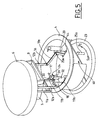
- FIG 5 there is shown a view to see the interior of the box 4.
- the system 5 is in the deployed position and the box 4 is provided with an opening 40 through which the system 5 can be reloaded in ammunition on the inner side of Turret after retraction of its cylinder head 9.
- This opening 40 can be closed by a shutter not shown in order to sealingly close the box 4.
- the first arms 11 are in the form of a U-shaped frame 11a fixed on either side of the cover 6, which frame is connected to the axis 17 by a single arm 11b.
- This embodiment makes it possible to implement a single pinion 31 / worm gear system 30 without any modification of the operation.
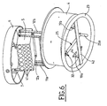
- the cupola is shown in a bottom view where we see the steering wheel 23, the control member 25, the angle returns 19a and 19b integral with a diametral bar 42 fixed to the steering wheel 23 and a slot 44.
- the brackets 7 hooking system 5 to cover 6 and its multiple tubes 41 We still see the realization of the frame 11a.
- This figure also shows the end of the axis 32 on which the control member 25 is fixed.
Landscapes
- Engineering & Computer Science (AREA)
- General Engineering & Computer Science (AREA)
- Toys (AREA)
- Lock And Its Accessories (AREA)
- Mechanical Pencils And Projecting And Retracting Systems Therefor, And Multi-System Writing Instruments (AREA)
- Gear Transmission (AREA)
- Steering Devices For Bicycles And Motorcycles (AREA)
- Manipulator (AREA)
- Forklifts And Lifting Vehicles (AREA)
- Blinds (AREA)
Abstract
Description
- Le secteur technique de la présente invention est celui des tourelleaux montés sur une plate-forme.
- On connaît des tourelleaux équipant une plate-forme (véhicule, bâtiment ,...) et destinés à supporter un système actif constitué d'armes offensives ou défensives et/ou d'un moyen de vision déportée tel un épiscope ou une caméra. On connaît également des dispositifs de type canons présentant plusieurs tubes montés en batterie. Ils ne sont pas orientables et présentent une importante structure rigide capable de supporter les efforts. On connaît également des systèmes d'armes déployables, mais ces systèmes d'armes ne sont pas rechargeables depuis l'intérieur d'un véhicule.
- L'invention se rapporte donc à un tourelleau monté de manière escamotable et comportant des moyens de déploiement manuel afin de l'amener dans une position d'utilisation.
- L'invention a pour objet un tourelleau escamotable monté rotatif sur une plate-forme, comprenant un système actif orientable en site et en gisement, un capot de protection du système actif fermant un caisson, caractérisé en ce qu'il comporte des moyens de déploiement du système actif constitués par un premier et un second bras formant un parallélogramme déformable disposés de part et d'autre du système actif et des moyens de pointage en site et en gisement dudit système actif, le déploiement étant commandé par un premier moyen manuel actionnant le premier bras, l'orientation en site et en gisement du système actif étant commandé par un second moyen manuel actionnant le second bras.
- Selon une caractéristique de l'invention, le premier bras est relié en rotation à un axe solidaire d'un support (18) fixé au caisson.
- Selon une autre caractéristique de l'invention, le premier moyen manuel est constitué par un ensemble pignon et vis sans fin relié à un organe de commande pour orienter en gisement le système actif.
- Selon une autre caractéristique de l'invention, la vis sans fin est solidaire de l'axe donc du premier bras et le pignon est solidaire de l'organe de commande.
- Selon une autre caractéristique de l'invention, l'organe de commande est manoeuvrable latéralement pour entraîner en rotation le pignon qui entraîne la vis sans fin.
- Selon une autre caractéristique de l'invention, le second bras est relié en rotation à un renvoi d'angle se présentant sous la forme d'un L solidaire en rotation d'un support fixé au caisson, une extrémité du L étant reliée à ce second bras et l'autre extrémité à un volant de manoeuvre pour orienter en site ledit système actif.
- Selon une autre caractéristique de l'invention, le couvercle est relié au système actif par l'intermédiaire d'au moins une patte de fixation constituant une articulation, un moyen ressort étant prévu permettant de faire pivoter le couvercle de façon à dégager une face avant du système actif en position déployée.
- Selon une autre caractéristique de l'invention, le volant est manoeuvrable suivant deux directions, l'une dans un plan horizontal pour positionner en gisement ou direction le système actif et l'autre dans un plan vertical pour positionner le système actif en site ou en élévation.
- Selon une autre caractéristique de l'invention, le caisson forme une enceinte fermée permettant d'assurer l'étanchéité entre l'extérieur et l'intérieur de la plate-forme, le caisson comportant une ouverture fermée par un volet permettant d'accéder au système actif lorsque ce dernier est en position escamotée.
- Selon une autre caractéristique de l'invention, le système actif est orientable en site selon un angle compris entre -10° et 60°.
- Un tout premier avantage du tourelleau selon l'invention réside dans le fait qu'il occupe un volume réduit et autorise de ce fait un rechargement possible en munitions dans toute les positions et sur la totalité de la zone de giration.
- Un autre avantage de l'invention réside dans l'absence de besoin en énergie électrique pour amener le tourelleau dans ses positions de site et de gisement.
- Un autre avantage encore de l'invention réside dans le fait que l'orientation en site ne nécessite que des mouvements de traction et d'extension d'amplitude modérée et facilement réalisables par un opérateur même dans un espace réduit.
- D'autres caractéristiques, détails et avantages de l'invention ressortiront plus clairement de la description détaillée donnée ci-après à titre indicatif en relation avec des vues perspectives sur lesquelles:
- la
figure 1 représente le tourelleau selon l'invention en position repliée, - la
figure 2 représente le tourelleau selon l'invention en position déployée, - la
figure 3 montre le tourelleau selon l'invention orienté en site en position extrême basse, - la
figure 4 représente le tourelleau orienté en site en position extrême haute, - la
figure 5 est une vue montrant l'intérieur du tourelleau, et - la
figure 6 est une vue montrant la paroi inférieure du tourelleau. - Il est connu que les tourelleaux peuvent supporter un ou plusieurs systèmes actifs. Ces systèmes peuvent être des moyens de vision, des armes ou des moyens de défense. Dans les exemples de réalisation décrits par la suite, ce système actif est représenté par un bloc multitubes permettant le tir de projectiles (par exemple de masquage ou de leurrage). Bien entendu, cet exemple n'est pas limitatif et on pourra remplacer ce bloc multitube par n'importe quel autre système actif. Les tourelleaux sont destinées à équiper une plate-forme telle un véhicule ou une structure fixe telle un bâtiment, où on distinguera l'extérieur et l'intérieur.
- La
figure 1 représente en coupe un tourelleau 1 selon l'invention fixé sur une plate-forme 2 par l'intermédiaire d'un roulement 3 autorisant une rotation de 360° de ce tourelleau. Bien entendu, des moyens d'étanchéité (non représenté), par exemple un joint, sont prévus entre le tourelleau 1 et la plate-forme 2 afin d'isoler l'intérieur de celle-ci du milieu extérieur. Le tourelleau comprend un caisson 4 renfermant un système actif 5 et relié à celui-ci par un parallélogramme déformable. Le caisson 4 est fermé par un capot de protection 6 qui est fixé au système actif 5 par une patte de fixation 7 qui constitue une articulation. Un moyen ressort 43 est prévu entre le couvercle 6 et une patte arrière 8 solidaire du système actif 5. Ainsi, lors du déploiement du système 5, le couvercle 6 pivote sur son articulation et bascule par l'action du ressort 43. Une telle disposition permet de dégager la face avant du système actif 5 en position déployée. - Sur la
figure 1 , le système 5 est dans la position repliée et le ressort 43 est en extension. - Le système actif 5 est constitué ici par un bloc muni de tubes de lancement 41 renfermant des munitions et fermé à l'arrière par une culasse 9. Sur la figure, la culasse 9 est représentée en position ouverte en étant reliée au bloc par une articulation 10. En position ouverte, le bloc est accessible afin de le charger en munitions à partir de l'intérieur de la plate-forme 2 où se trouvent les servants du tourelleau. La culasse mobile 9 comprenant un système de percussion est verrouillée en partie arrière du bloc et assure la chaîne de mise à feu de la munition sélectionnée. Un moyen de déverrouillage permet de déverrouiller cette culasse mobile.
- Le parallélogramme déformable est constitué par un ensemble de bras disposés de part et d'autre du système 5. Sur la figure on voit une seule paire de bras, un premier bras 11 et un second bras 12. Ce parallélogramme constitue le moyen de déploiement du système actif 5 pour l'amener de la position repliée ou fermée représentée sur cette figure à une position déployée décrite ci-après. Les bras 11 et 12 sont reliés au système 5 par les articulations respectives 13 et 14 et au caisson 4 par les articulations respectives 15 et 16.
- Le premier bras 11 est solidaire d'un axe 17 (
figure 5 ) qui pivote au niveau des articulations 15 par rapport à deux supports 18 fixés au caisson 4 (voirfigure 5 ). L'articulation 16 du second bras 12 est reliée à un renvoi d'angle 19 se présentant sous la forme d'un L pivotant sur un axe 20a solidaire d'un support 20 fixé au caisson 4. Une extrémité 21 du L est reliée au second bras 12 par une articulation 16 et l'autre extrémité 22 est solidaire d'un volant 23 de manoeuvre pour orienter en site ledit système actif 5. - Le volant 23 est manoeuvrable suivant les deux directions Y et Z.
- Suivant la direction Y sensiblement horizontale et qui est perpendiculaire au plan de la
figure 1 , le volant 23 est fixe par rapport au caisson 4. Il est possible alors de faire pivoter manuellement le caisson 4 sur le roulement 3 de façon à orienter en gisement (ou en direction) ce caisson 4 (ainsi que le système 5). Le pivotement peut être effectué sur 360° grâce au roulement 3. Ainsi, le système 4 peut être orienté en gisement à tout moment par le servant occupant l'intérieur de la plate-forme dans n'importe quelle direction. - Suivant la direction Z qui est dans le plan de la
figure 1 sensiblement vertical, le volant 23 qui est solidaire du renvoi 19 peut pivoter autour de l'axe 20a pour déplacer le second bras 12 comme cela sera expliqué ci-après et orienter ainsi en site (ou élévation) le système 5. - Le parallélogramme peut par ailleurs être déformé pour passer de la position repliée montrée sur la
figure 1 à la position déployée montrée sur lafigure 2 . - Pour cela un premier moyen manuel permet de faire pivoter le premier bras 11 sur son articulation 15. Le premier moyen manuel 24 est constitué par un ensemble comprenant un pignon 31 engrenant avec une vis sans fin 30.
- La vis sans fin 30 est solidaire de l'axe 17 (
figure 5 ) qui est lui-même solidaire du premier bras 11. Une rotation de la vis sans fin 30 entraîne donc le pivotement du bras 11 sur les articulations 15 par rapport aux supports 18. - Le pignon 31 est solidaire en rotation d'un axe 32 qui peut pivoter par rapport au caisson 4 sur des paliers (non représentés). L'axe 32 est par ailleurs solidaire d'un organe de commande 25 doté d'une poignée 25a. Une action manuelle sur la poignée 25a permet de faire pivoter dans un plan horizontal (flèches S1, S2 -
figure 5 ) l'organe de commande 25 ce qui fait tourner l'axe 32 sur ses paliers ainsi que le pignon 31. - Pour améliorer la clarté des
figures 5 et6 , on a représenté sur ces dernières l'organe de commande 25 dans une position médiane. Il est clair que cet organe ne peut pivoter avec l'axe 32 suivant les directions S1 et S2 que jusqu'à la mise en butée de la poignée 25a sur une barre diamétrale 42 solidaire du volant 23. - Afin d'utiliser la course angulaire maximale disponible pour l'organe 25, ce dernier se trouvera donc avec sa poignée 25a en butée contre la barre 42 dans ses positions repliée et déployée. Un premier sens S1 sera alors le sens de manoeuvre pour le déploiement du système 5 et le sens inverse S2 sera celui adopté pour le repliement du système 5. La course angulaire de l'organe 25 sera alors voisine de 90°. L'Homme du Métier définira le pignon 31 et la vis 30 de telle sorte qu'un pivotement de l'organe de commande 25 d'un angle d'environ 80 à 90° assure le déploiement complet du système.
- Le pignon 31 est engagé dans la vis sans fin 30. Par sa rotation, il fait donc pivoter cette dernière ce qui provoque la rotation du premier bras 11 et le déploiement du système 5 hors du caisson 4.
- Sur la
figure 2 , on a représentée une position déployée du système 5. On voit sur cette figure la vis 30 fixée au bras 11 et le pignon 31 solidaire de l'axe 32, pivotant par rapport au caisson 4, et solidaire de l'organe de commande 25. En actionnant l'organe 25, on entraîne en rotation le pignon 31 et conséquemment le premier bras 11 passe de la position repliée représentée sur lafigure 1 à la position déployée de lafigure 2 . Sur cette figure, on voit encore que le couvercle 6 a basculé par rapport au système 5 par l'action du ressort 43. Le couvercle occupe ainsi sa seconde position et permet d'éviter toute interférence entre les munitions éjectées et le couvercle 6. - Sur la
figure 3 , on a représenté une position déployée du système 5 avec orientation basse en site, position suivant laquelle le volant 23 a été manoeuvré en basculement suivant la direction Z1 grâce à la rotation du renvoi d'angle 19 autour de l'axe 20a à travers une fente 44 du caisson 4. Le renvoi d'angle entraîne alors en translation le second bras 12 dans une position haute extrême sans modification de la position du premier bras 11. Cette rotation permet d'amener le système 5 suivant un angle de site négatif d'environ -5° par rapport à l'horizontale. Bien entendu, le système 5 peut être orienté suivant toutes les positions intermédiaires. - Sur la
figure 4 , on a représenté une position déployée du système 5 avec orientation haute en site, position suivant laquelle le volant 23 a été manoeuvré en élévation suivant la direction Z2 grâce à la rotation du renvoi d'angle 19 autour de l'axe 20a. Le renvoi d'angle 19 entraîne alors en translation le second bras 12 dans une position basse extrême sans modification de la position du premier bras 11. Cette rotation permet d'amener le système 5 suivant un angle de site d'environ +60°. Là encore, le système 5 peut être orienté suivant toutes les positions intermédiaires. - On voit que le tourelleau selon l'invention permet d'amener un système actif d'une position repliée à une position déployée (grâce à l'organe 25) et que par ailleurs il permet (avec le volant 23) de régler le site (élévation) du système suivant une plage angulaire de -5° à +60° ainsi que le gisement suivant 360°.
- Le réglage en site peut être réalisé dans n'importe quelle position en gisement du système par de simples manoeuvres manuelles du volant 23. Ainsi, en adjoignant au second bras 12 le renvoi d'angle 19, on assure l'orientation en site (élévation) en conservant une compacité de l'ensemble pour le loger dans le caisson 4.
- Les commandes manuelles 23 et 25 du système actif 5 permettent de s'affranchir de tout moyen nécessitant de l'énergie électrique assurant la disponibilité du tourelleau quelles que soient les circonstances.
- Sur la
figure 5 , on a représenté une vue permettant de voir l'intérieur du caisson 4. Sur cette figure, le système 5 est en position déployée et le caisson 4 est muni d'une ouverture 40 par l'intermédiaire de laquelle le système 5 peut être rechargé en munitions du côté intérieur du tourelleau après escamotage de sa culasse 9. Cette ouverture 40 peut être fermée par un volet non représenté afin de fermer de manière étanche le caisson 4. On voit encore les seconds bras 12a et 12b reliés aux renvois d'angle 19a et 19b dont un seul le 19a est visible sur cette figure, et est relié au support 20 et parcours la fente 44 pour occuper les deux positions extrêmes indiquées précédemment. Dans cette réalisation, les premiers bras 11 se présentent sous la forme d'un cadre 11a en forme de U fixé de part et d'autre du couvercle 6, lequel cadre est relié à l'axe 17 par un bras unique 11b. Cette réalisation permet de mettre en oeuvre un unique système 24 de pignon 31 / vis sans fin 30 sans modification du fonctionnement. - Sur la
figure 6 , on a représenté le tourelleau en vue de dessous où on voit le volant 23, l'organe de commande 25, les renvois d'angle 19a et 19b solidaires d'une barre diamétrale 42 fixée au volant 23 et une fente 44. On voit également les pattes 7 d'accrochage du système 5 au capot 6 et ses tubes multiples 41. On voit encore la réalisation du cadre 11a. On voit aussi sur cette figure l'extrémité de l'axe 32 sur laquelle est fixé l'organe de commande 25. - L'homme du métier déterminera de manière simple la réalisation des bras constituant le parallélogramme de manière à assurer la résistance nécessaire pour absorber les contraintes de tir des munitions. Ces munitions peuvent être identiques ou différentes, de même calibre ou de calibre différent.
Claims (10)
- Tourelleau escamotable (1) monté rotatif sur une plate-forme (2), comprenant un système actif (5) orientable en site et en gisement, un capot (6) de protection du système actif fermant un caisson (4), caractérisé en ce qu'il comporte des moyens de déploiement du système actif constitués par un premier et un second bras (11, 12) formant un parallélogramme déformable disposés de part et d'autre du système actif (5) et des moyens de pointage en site et en gisement (23, 25) dudit système actif, le déploiement étant commandé par un premier moyen manuel (24, 25) actionnant le premier bras (11), l'orientation en site et en gisement du système actif étant commandé par un second moyen manuel (19, 30) actionnant le second bras (12).
- Tourelleau escamotable (1) selon la revendication 1, caractérisé en ce que le premier bras (11) est relié en rotation à un axe (15) solidaire d'un support (18) fixé au caisson (4).
- Tourelleau escamotable (1) selon la revendication 2, caractérisé en ce que le premier moyen manuel (24, 25) est constitué par un ensemble (24) pignon (31) et vis sans fin (30) relié à un organe de commande (25) pour orienter en gisement le système actif (5).
- Tourelleau escamotable (1) 1 selon la revendication 3, caractérisé en ce que la vis sans fin (30) est solidaire de l'axe (15) donc du premier bras (11) et le pignon (31) est solidaire de l'organe de commande (25).
- Tourelleau escamotable (1) selon la revendication 3 ou 4, caractérisé en ce que l'organe de commande (25) est manoeuvrable latéralement pour entraîner en rotation le pignon (31) qui entraîne la vis sans fin (24).
- Tourelleau escamotable (1) selon l'une des revendications précédentes, caractérisé en ce que le second bras (12) est relié en rotation à un renvoi d'angle (19) se présentant sous la forme d'un L solidaire en rotation d'un support fixé (20) au caisson (4), une extrémité (21) du L étant reliée à ce second bras (12) et l'autre extrémité (22) à un volant (23) de manoeuvre pour orienter en site ledit système actif (5).
- Tourelleau escamotable (1) selon l'une des revendications précédentes, caractérisé en ce que le couvercle (6) est relié au système actif (5) par l'intermédiaire d'au moins une patte de fixation (7) constituant une articulation, un moyen ressort (43) étant prévu permettant de faire pivoter le couvercle (6) de façon à dégager une face avant du système actif en position déployée.
- Tourelleau escamotable (1) selon l'une des revendication précédentes, caractérisé en ce que le volant (23) est manoeuvrable suivant deux directions, l'une dans un plan horizontal pour positionner en gisement ou direction le système actif (5) et l'autre dans un plan vertical pour positionner en site ou élévation le système actif (5).
- Tourelleau escamotable (1) selon l'une quelconque des revendications précédentes, caractérisé en ce que le caisson (4) forme une enceinte fermée permettant d'assurer l'étanchéité entre l'extérieur et l'intérieur de la plate-forme (1), le caisson comportant une ouverture (40) fermée par un volet permettant d'accéder au système actif (5) lorsque ce dernier est en position escamotée.
- Tourelleau escamotable (1) selon l'une des revendications précédentes, caractérisé en ce que le système actif (5) est orientable en site selon un angle compris entre -10° et 60°.
Priority Applications (1)
| Application Number | Priority Date | Filing Date | Title |
|---|---|---|---|
| PL09290676T PL2169341T3 (pl) | 2008-09-24 | 2009-09-07 | Ręcznie chowana wieżyczka |
Applications Claiming Priority (1)
| Application Number | Priority Date | Filing Date | Title |
|---|---|---|---|
| FR0805234A FR2936305B1 (fr) | 2008-09-24 | 2008-09-24 | Tourelleau escamotable manuellement |
Publications (2)
| Publication Number | Publication Date |
|---|---|
| EP2169341A1 true EP2169341A1 (fr) | 2010-03-31 |
| EP2169341B1 EP2169341B1 (fr) | 2011-06-22 |
Family
ID=40688310
Family Applications (1)
| Application Number | Title | Priority Date | Filing Date |
|---|---|---|---|
| EP09290676A Active EP2169341B1 (fr) | 2008-09-24 | 2009-09-07 | Tourelleau escamotable manuellement |
Country Status (5)
| Country | Link |
|---|---|
| US (1) | US8393258B2 (fr) |
| EP (1) | EP2169341B1 (fr) |
| AT (1) | ATE514046T1 (fr) |
| FR (1) | FR2936305B1 (fr) |
| PL (1) | PL2169341T3 (fr) |
Cited By (1)
| Publication number | Priority date | Publication date | Assignee | Title |
|---|---|---|---|---|
| EP2746714A3 (fr) * | 2012-12-22 | 2016-07-20 | Diehl BGT Defence GmbH & Co.KG | Conteneur pour missile |
Families Citing this family (14)
| Publication number | Priority date | Publication date | Assignee | Title |
|---|---|---|---|---|
| US8584573B2 (en) * | 2010-02-04 | 2013-11-19 | Quantum Fuel Systems Technologies Worldwide Inc. | Orbital device with stowable mount |
| DE102010060192B9 (de) * | 2010-10-26 | 2013-01-24 | Krauss-Maffei Wegmann Gmbh & Co. Kg | Befestigungsvorrichtung und Fahrzeug |
| ITTO20110455A1 (it) * | 2011-05-25 | 2012-11-26 | Oto Melara Spa | Assieme di torretta e arma a bassa riflessione radar. |
| WO2013183047A1 (fr) | 2012-06-04 | 2013-12-12 | Rafael Advanced Defense Systems Ltd. | Station d'arme non létale commandée à distance |
| DE102013101635A1 (de) | 2013-02-19 | 2014-08-21 | Krauss-Maffei Wegmann Gmbh & Co. Kg | Waffenstation |
| US10371479B2 (en) * | 2013-09-11 | 2019-08-06 | Merrill Aviation, Inc. | Stabilized integrated commander's weapon station for combat armored vehicle |
| MX391840B (es) | 2015-09-29 | 2025-03-21 | Russell Frank | Sistema de torreta de cubierta para camper. |
| MY206980A (en) * | 2017-08-17 | 2025-01-23 | Mac Jee Ind De Defesa Ltda | Rocket launch module and rocket launch vehicle |
| US10309745B2 (en) * | 2017-11-09 | 2019-06-04 | Samuel Messinger | Mobile turret weapon delivery system |
| DE202018103226U1 (de) * | 2018-06-08 | 2018-10-11 | Rheinmetall Landsysteme Gmbh | Zusatzsystemanordnung für ein Fahrzeug |
| EP3660443B1 (fr) | 2018-11-28 | 2021-10-20 | John Cockerill Defense S.A. | Tourelle avec toit de protection escamotable |
| PL3699542T3 (pl) * | 2019-02-21 | 2022-02-07 | John Cockerill Defense S.A. | Pojazd niewykrywalny ze zintegrowanym systemem szybkiego rozłożenia uzbrojenia w pozycji gotowości do użycia |
| US20220397365A1 (en) * | 2021-06-11 | 2022-12-15 | Alexander RIVERA | Turret apparatus |
| US12123672B1 (en) * | 2023-06-20 | 2024-10-22 | United States Of America, As Represented By The Secretary Of The Navy | Modular tube-stowable rifle mount |
Citations (6)
| Publication number | Priority date | Publication date | Assignee | Title |
|---|---|---|---|---|
| GB118669A (en) * | 1917-09-04 | 1918-09-04 | Edouard Nieuwenhuyse | Improvements in Gun Mountings. |
| FR494292A (fr) * | 1917-02-14 | 1919-09-04 | Louis Pierre Jacques Chapplain | Canon de tranchée à éclipse automatique |
| DE932297C (de) * | 1952-03-20 | 1955-08-29 | Fritz Beeck | Panzer-Spaehwagen mit hoehenverstellbarer gepanzerter Kanzel |
| FR2149637A6 (fr) * | 1963-11-28 | 1973-03-30 | Aerospatiale | |
| DE4304761A1 (de) * | 1993-02-17 | 1994-08-18 | Mak System Gmbh | Waffenlafette für Panzerfahrzeuge |
| WO2004097325A2 (fr) * | 2003-01-21 | 2004-11-11 | United Defense, L.P. | Systeme d'arme a ejection |
Family Cites Families (18)
| Publication number | Priority date | Publication date | Assignee | Title |
|---|---|---|---|---|
| DE1259737B (de) * | 1964-11-06 | 1968-01-25 | Boelkow Gmbh | Abschuss- und Ladevorrichtung fuer rueckstossgetriebene Flugkoerper, die aus richtbaren Wechselmagazinen einzeln nacheinander oder gleichzeitig gestartet werden koennen |
| US3757635A (en) * | 1971-03-23 | 1973-09-11 | F Hickerson | Multi-purpose munitions carrier |
| US3865009A (en) * | 1973-09-13 | 1975-02-11 | Us Navy | Launcher mount |
| FR2380527A2 (fr) * | 1977-02-11 | 1978-09-08 | Creusot Loire | Installation de lancement de missiles |
| US4282794A (en) * | 1979-04-30 | 1981-08-11 | Miller Avy L | Self-propelled off-road vehicle |
| US4481862A (en) * | 1982-07-13 | 1984-11-13 | Fmc Corporation | Automatic loading system for fixed ammunition at gun elevation |
| US4574685A (en) * | 1983-06-22 | 1986-03-11 | Am General Corporation | Turret system for lightweight military vehicle |
| DE3440041A1 (de) * | 1984-11-02 | 1986-05-07 | Rheinmetall GmbH, 4000 Düsseldorf | Hochschwenkbare scheitellafettierung fuer das waffenrohr eines kampfpanzers |
| DE3603623A1 (de) * | 1986-02-06 | 1987-08-13 | Salgad Int Ltd | Hoehenricht-vorrichtung fuer das abschussrohr eines granatwerfers |
| GB8817274D0 (en) * | 1988-07-20 | 1988-12-14 | Marconi Co Ltd | Weapon systems |
| US5129308A (en) * | 1989-03-21 | 1992-07-14 | Fuereder Georg F | Combat vehicle with extendible combat platform |
| DE4401587A1 (de) * | 1994-01-20 | 1995-07-27 | Wegmann & Co Gmbh | Kampffahrzeug sowie Transportsystem zu seiner Verladung in Transportflugzeuge |
| US6584881B1 (en) * | 2001-03-26 | 2003-07-01 | United Defense Lp | Multi-purpose missile launcher system for a military land vehicle |
| WO2003025494A1 (fr) * | 2001-08-30 | 2003-03-27 | Krauss-Maffei Wegmann Gmbh & Co. Kg | Canon d'artillerie comprenant une arme lourde montee sur un vehicule de soutien |
| DE20214679U1 (de) * | 2002-09-23 | 2004-02-19 | Krauss-Maffei Wegmann Gmbh & Co. Kg | Einrichtung zur Anpassung eines mehrere Artillerieraketen enthaltenden Containers an eine Abschußvorrichtung für Artillerieraketen |
| US7669513B2 (en) * | 2003-10-09 | 2010-03-02 | Elbit Systems Ltd. | Multiple weapon system for armored vehicle |
| ITMI20060668A1 (it) * | 2006-04-05 | 2007-10-06 | Oto Melara Spa | Dispositivo ausiliario di puntamento |
| US8146479B2 (en) * | 2009-09-10 | 2012-04-03 | Nexter Systems | Retractable light turret |
-
2008
- 2008-09-24 FR FR0805234A patent/FR2936305B1/fr not_active Expired - Fee Related
-
2009
- 2009-09-07 PL PL09290676T patent/PL2169341T3/pl unknown
- 2009-09-07 AT AT09290676T patent/ATE514046T1/de active
- 2009-09-07 EP EP09290676A patent/EP2169341B1/fr active Active
- 2009-09-23 US US12/585,726 patent/US8393258B2/en not_active Expired - Fee Related
Patent Citations (6)
| Publication number | Priority date | Publication date | Assignee | Title |
|---|---|---|---|---|
| FR494292A (fr) * | 1917-02-14 | 1919-09-04 | Louis Pierre Jacques Chapplain | Canon de tranchée à éclipse automatique |
| GB118669A (en) * | 1917-09-04 | 1918-09-04 | Edouard Nieuwenhuyse | Improvements in Gun Mountings. |
| DE932297C (de) * | 1952-03-20 | 1955-08-29 | Fritz Beeck | Panzer-Spaehwagen mit hoehenverstellbarer gepanzerter Kanzel |
| FR2149637A6 (fr) * | 1963-11-28 | 1973-03-30 | Aerospatiale | |
| DE4304761A1 (de) * | 1993-02-17 | 1994-08-18 | Mak System Gmbh | Waffenlafette für Panzerfahrzeuge |
| WO2004097325A2 (fr) * | 2003-01-21 | 2004-11-11 | United Defense, L.P. | Systeme d'arme a ejection |
Cited By (1)
| Publication number | Priority date | Publication date | Assignee | Title |
|---|---|---|---|---|
| EP2746714A3 (fr) * | 2012-12-22 | 2016-07-20 | Diehl BGT Defence GmbH & Co.KG | Conteneur pour missile |
Also Published As
| Publication number | Publication date |
|---|---|
| EP2169341B1 (fr) | 2011-06-22 |
| FR2936305B1 (fr) | 2010-10-22 |
| ATE514046T1 (de) | 2011-07-15 |
| PL2169341T3 (pl) | 2011-11-30 |
| FR2936305A1 (fr) | 2010-03-26 |
| US8393258B2 (en) | 2013-03-12 |
| US20100071540A1 (en) | 2010-03-25 |
Similar Documents
| Publication | Publication Date | Title |
|---|---|---|
| EP2169341B1 (fr) | Tourelleau escamotable manuellement | |
| EP1468240B1 (fr) | Tourelle pour vehicule militaire | |
| EP0411993B1 (fr) | Affût anti-aérien léger déployable | |
| EP2071268B1 (fr) | Tourelleau escamotable | |
| CA2790463A1 (fr) | Systeme d'acces a un habitacle | |
| EP4042088B1 (fr) | Conteneur logistique destiné à être équipé d'au moins un moyen de protection | |
| EP1535017B1 (fr) | Systeme de defense d'une cible comprenant un dispositif lanceur de projectiles | |
| FR2549218A1 (fr) | Vehicule blinde equipe d'un mortier | |
| EP2163843B1 (fr) | Tourelleau escamotable | |
| FR2520861A1 (fr) | Support de mortier sur vehicule blinde | |
| EP3699542B1 (fr) | Véhicule furtif avec système d'arme integré à déploiement rapide | |
| EP3755966B1 (fr) | Dispositif de protection pour un viseur orientable en site | |
| EP3029409B1 (fr) | Tourelleau pour arme de petit calibre | |
| EP0017591B1 (fr) | Véhicule de combat à canon alimenté de façon automatique | |
| FR2654819A1 (fr) | Affut pour une arme legere sur des vehicules blindes. | |
| FR3022338A1 (fr) | Tourelleau comportant un magasin a munitions | |
| EP4317903B1 (fr) | Montage d'arme et tourelle comportant un tel montage d'arme | |
| EP3542121B1 (fr) | Systeme de tir de projectile | |
| EP2956738B1 (fr) | Systeme d'arme leger | |
| FR2704055A1 (fr) | Arme de guerre à élément actif à redressement autonome. | |
| EP0140053A2 (fr) | Mortier capable d'être monté sur un véhicule | |
| FR2827950A1 (fr) | Systeme de defense d'une cible comprenant un dispositif lanceur de projectiles | |
| FR2522132A1 (fr) | Dispositif de reperage horizontal d'un periscope monte sur un tube d'une piece d'artillerie | |
| EP4339550A2 (fr) | Tourelle avec toit de protection escamotable | |
| FR2897423A1 (fr) | Dispositif de compensation de la trainee aerodynamique d'un systeme d'arme |
Legal Events
| Date | Code | Title | Description |
|---|---|---|---|
| PUAI | Public reference made under article 153(3) epc to a published international application that has entered the european phase |
Free format text: ORIGINAL CODE: 0009012 |
|
| AK | Designated contracting states |
Kind code of ref document: A1 Designated state(s): AT BE BG CH CY CZ DE DK EE ES FI FR GB GR HR HU IE IS IT LI LT LU LV MC MK MT NL NO PL PT RO SE SI SK SM TR |
|
| AX | Request for extension of the european patent |
Extension state: AL BA RS |
|
| 17P | Request for examination filed |
Effective date: 20100930 |
|
| GRAP | Despatch of communication of intention to grant a patent |
Free format text: ORIGINAL CODE: EPIDOSNIGR1 |
|
| GRAS | Grant fee paid |
Free format text: ORIGINAL CODE: EPIDOSNIGR3 |
|
| GRAA | (expected) grant |
Free format text: ORIGINAL CODE: 0009210 |
|
| RIN1 | Information on inventor provided before grant (corrected) |
Inventor name: CAZALIERES, JEAN-FRANCOIS Inventor name: GUILLARD, JEROME |
|
| AK | Designated contracting states |
Kind code of ref document: B1 Designated state(s): AT BE BG CH CY CZ DE DK EE ES FI FR GB GR HR HU IE IS IT LI LT LU LV MC MK MT NL NO PL PT RO SE SI SK SM TR |
|
| REG | Reference to a national code |
Ref country code: GB Ref legal event code: FG4D Free format text: NOT ENGLISH |
|
| REG | Reference to a national code |
Ref country code: CH Ref legal event code: EP |
|
| REG | Reference to a national code |
Ref country code: CH Ref legal event code: NV Representative=s name: ING. MARCO ZARDI C/O M. ZARDI & CO. S.A. |
|
| REG | Reference to a national code |
Ref country code: IE Ref legal event code: FG4D Free format text: LANGUAGE OF EP DOCUMENT: FRENCH |
|
| REG | Reference to a national code |
Ref country code: DE Ref legal event code: R096 Ref document number: 602009001610 Country of ref document: DE Effective date: 20110804 |
|
| REG | Reference to a national code |
Ref country code: SE Ref legal event code: TRGR |
|
| REG | Reference to a national code |
Ref country code: NL Ref legal event code: VDEP Effective date: 20110622 |
|
| PG25 | Lapsed in a contracting state [announced via postgrant information from national office to epo] |
Ref country code: NO Free format text: LAPSE BECAUSE OF FAILURE TO SUBMIT A TRANSLATION OF THE DESCRIPTION OR TO PAY THE FEE WITHIN THE PRESCRIBED TIME-LIMIT Effective date: 20110922 Ref country code: HR Free format text: LAPSE BECAUSE OF FAILURE TO SUBMIT A TRANSLATION OF THE DESCRIPTION OR TO PAY THE FEE WITHIN THE PRESCRIBED TIME-LIMIT Effective date: 20110622 Ref country code: LT Free format text: LAPSE BECAUSE OF FAILURE TO SUBMIT A TRANSLATION OF THE DESCRIPTION OR TO PAY THE FEE WITHIN THE PRESCRIBED TIME-LIMIT Effective date: 20110622 |
|
| PG25 | Lapsed in a contracting state [announced via postgrant information from national office to epo] |
Ref country code: FI Free format text: LAPSE BECAUSE OF FAILURE TO SUBMIT A TRANSLATION OF THE DESCRIPTION OR TO PAY THE FEE WITHIN THE PRESCRIBED TIME-LIMIT Effective date: 20110622 Ref country code: CY Free format text: LAPSE BECAUSE OF FAILURE TO SUBMIT A TRANSLATION OF THE DESCRIPTION OR TO PAY THE FEE WITHIN THE PRESCRIBED TIME-LIMIT Effective date: 20110622 Ref country code: GR Free format text: LAPSE BECAUSE OF FAILURE TO SUBMIT A TRANSLATION OF THE DESCRIPTION OR TO PAY THE FEE WITHIN THE PRESCRIBED TIME-LIMIT Effective date: 20110923 Ref country code: SI Free format text: LAPSE BECAUSE OF FAILURE TO SUBMIT A TRANSLATION OF THE DESCRIPTION OR TO PAY THE FEE WITHIN THE PRESCRIBED TIME-LIMIT Effective date: 20110622 Ref country code: LV Free format text: LAPSE BECAUSE OF FAILURE TO SUBMIT A TRANSLATION OF THE DESCRIPTION OR TO PAY THE FEE WITHIN THE PRESCRIBED TIME-LIMIT Effective date: 20110622 |
|
| REG | Reference to a national code |
Ref country code: PL Ref legal event code: T3 |
|
| PG25 | Lapsed in a contracting state [announced via postgrant information from national office to epo] |
Ref country code: NL Free format text: LAPSE BECAUSE OF FAILURE TO SUBMIT A TRANSLATION OF THE DESCRIPTION OR TO PAY THE FEE WITHIN THE PRESCRIBED TIME-LIMIT Effective date: 20110622 |
|
| REG | Reference to a national code |
Ref country code: IE Ref legal event code: FD4D |
|
| PG25 | Lapsed in a contracting state [announced via postgrant information from national office to epo] |
Ref country code: CZ Free format text: LAPSE BECAUSE OF FAILURE TO SUBMIT A TRANSLATION OF THE DESCRIPTION OR TO PAY THE FEE WITHIN THE PRESCRIBED TIME-LIMIT Effective date: 20110622 Ref country code: PT Free format text: LAPSE BECAUSE OF FAILURE TO SUBMIT A TRANSLATION OF THE DESCRIPTION OR TO PAY THE FEE WITHIN THE PRESCRIBED TIME-LIMIT Effective date: 20111024 Ref country code: EE Free format text: LAPSE BECAUSE OF FAILURE TO SUBMIT A TRANSLATION OF THE DESCRIPTION OR TO PAY THE FEE WITHIN THE PRESCRIBED TIME-LIMIT Effective date: 20110622 Ref country code: IS Free format text: LAPSE BECAUSE OF FAILURE TO SUBMIT A TRANSLATION OF THE DESCRIPTION OR TO PAY THE FEE WITHIN THE PRESCRIBED TIME-LIMIT Effective date: 20111022 Ref country code: IE Free format text: LAPSE BECAUSE OF FAILURE TO SUBMIT A TRANSLATION OF THE DESCRIPTION OR TO PAY THE FEE WITHIN THE PRESCRIBED TIME-LIMIT Effective date: 20110622 |
|
| PG25 | Lapsed in a contracting state [announced via postgrant information from national office to epo] |
Ref country code: SK Free format text: LAPSE BECAUSE OF FAILURE TO SUBMIT A TRANSLATION OF THE DESCRIPTION OR TO PAY THE FEE WITHIN THE PRESCRIBED TIME-LIMIT Effective date: 20110622 |
|
| PLBE | No opposition filed within time limit |
Free format text: ORIGINAL CODE: 0009261 |
|
| STAA | Information on the status of an ep patent application or granted ep patent |
Free format text: STATUS: NO OPPOSITION FILED WITHIN TIME LIMIT |
|
| PG25 | Lapsed in a contracting state [announced via postgrant information from national office to epo] |
Ref country code: MC Free format text: LAPSE BECAUSE OF NON-PAYMENT OF DUE FEES Effective date: 20110930 |
|
| 26N | No opposition filed |
Effective date: 20120323 |
|
| PG25 | Lapsed in a contracting state [announced via postgrant information from national office to epo] |
Ref country code: DK Free format text: LAPSE BECAUSE OF FAILURE TO SUBMIT A TRANSLATION OF THE DESCRIPTION OR TO PAY THE FEE WITHIN THE PRESCRIBED TIME-LIMIT Effective date: 20110622 |
|
| REG | Reference to a national code |
Ref country code: DE Ref legal event code: R097 Ref document number: 602009001610 Country of ref document: DE Effective date: 20120323 |
|
| PG25 | Lapsed in a contracting state [announced via postgrant information from national office to epo] |
Ref country code: MK Free format text: LAPSE BECAUSE OF FAILURE TO SUBMIT A TRANSLATION OF THE DESCRIPTION OR TO PAY THE FEE WITHIN THE PRESCRIBED TIME-LIMIT Effective date: 20110622 Ref country code: MT Free format text: LAPSE BECAUSE OF FAILURE TO SUBMIT A TRANSLATION OF THE DESCRIPTION OR TO PAY THE FEE WITHIN THE PRESCRIBED TIME-LIMIT Effective date: 20110622 |
|
| PG25 | Lapsed in a contracting state [announced via postgrant information from national office to epo] |
Ref country code: ES Free format text: LAPSE BECAUSE OF FAILURE TO SUBMIT A TRANSLATION OF THE DESCRIPTION OR TO PAY THE FEE WITHIN THE PRESCRIBED TIME-LIMIT Effective date: 20111003 Ref country code: SM Free format text: LAPSE BECAUSE OF FAILURE TO SUBMIT A TRANSLATION OF THE DESCRIPTION OR TO PAY THE FEE WITHIN THE PRESCRIBED TIME-LIMIT Effective date: 20110622 |
|
| PG25 | Lapsed in a contracting state [announced via postgrant information from national office to epo] |
Ref country code: LU Free format text: LAPSE BECAUSE OF NON-PAYMENT OF DUE FEES Effective date: 20110907 |
|
| PG25 | Lapsed in a contracting state [announced via postgrant information from national office to epo] |
Ref country code: BG Free format text: LAPSE BECAUSE OF FAILURE TO SUBMIT A TRANSLATION OF THE DESCRIPTION OR TO PAY THE FEE WITHIN THE PRESCRIBED TIME-LIMIT Effective date: 20110922 |
|
| PG25 | Lapsed in a contracting state [announced via postgrant information from national office to epo] |
Ref country code: HU Free format text: LAPSE BECAUSE OF FAILURE TO SUBMIT A TRANSLATION OF THE DESCRIPTION OR TO PAY THE FEE WITHIN THE PRESCRIBED TIME-LIMIT Effective date: 20110622 |
|
| REG | Reference to a national code |
Ref country code: FR Ref legal event code: PLFP Year of fee payment: 8 |
|
| REG | Reference to a national code |
Ref country code: FR Ref legal event code: PLFP Year of fee payment: 9 |
|
| REG | Reference to a national code |
Ref country code: FR Ref legal event code: PLFP Year of fee payment: 10 |
|
| PGFP | Annual fee paid to national office [announced via postgrant information from national office to epo] |
Ref country code: IT Payment date: 20190829 Year of fee payment: 11 |
|
| PGFP | Annual fee paid to national office [announced via postgrant information from national office to epo] |
Ref country code: AT Payment date: 20190822 Year of fee payment: 11 Ref country code: GB Payment date: 20190820 Year of fee payment: 11 |
|
| PGFP | Annual fee paid to national office [announced via postgrant information from national office to epo] |
Ref country code: CH Payment date: 20190820 Year of fee payment: 11 |
|
| REG | Reference to a national code |
Ref country code: CH Ref legal event code: PL |
|
| REG | Reference to a national code |
Ref country code: AT Ref legal event code: MM01 Ref document number: 514046 Country of ref document: AT Kind code of ref document: T Effective date: 20200907 |
|
| GBPC | Gb: european patent ceased through non-payment of renewal fee |
Effective date: 20200907 |
|
| PG25 | Lapsed in a contracting state [announced via postgrant information from national office to epo] |
Ref country code: AT Free format text: LAPSE BECAUSE OF NON-PAYMENT OF DUE FEES Effective date: 20200907 Ref country code: CH Free format text: LAPSE BECAUSE OF NON-PAYMENT OF DUE FEES Effective date: 20200930 Ref country code: GB Free format text: LAPSE BECAUSE OF NON-PAYMENT OF DUE FEES Effective date: 20200907 Ref country code: LI Free format text: LAPSE BECAUSE OF NON-PAYMENT OF DUE FEES Effective date: 20200930 |
|
| PG25 | Lapsed in a contracting state [announced via postgrant information from national office to epo] |
Ref country code: IT Free format text: LAPSE BECAUSE OF NON-PAYMENT OF DUE FEES Effective date: 20200907 |
|
| REG | Reference to a national code |
Ref country code: BE Ref legal event code: HC Owner name: KNDS FRANCE; FR Free format text: DETAILS ASSIGNMENT: CHANGE OF OWNER(S), CHANGE OF OWNER(S) NAME; FORMER OWNER NAME: NEXTER SYSTEMS Effective date: 20240530 |
|
| PGFP | Annual fee paid to national office [announced via postgrant information from national office to epo] |
Ref country code: DE Payment date: 20250820 Year of fee payment: 17 |
|
| PGFP | Annual fee paid to national office [announced via postgrant information from national office to epo] |
Ref country code: TR Payment date: 20250902 Year of fee payment: 17 Ref country code: PL Payment date: 20250825 Year of fee payment: 17 |
|
| PGFP | Annual fee paid to national office [announced via postgrant information from national office to epo] |
Ref country code: BE Payment date: 20250820 Year of fee payment: 17 |
|
| PGFP | Annual fee paid to national office [announced via postgrant information from national office to epo] |
Ref country code: FR Payment date: 20250820 Year of fee payment: 17 |
|
| PGFP | Annual fee paid to national office [announced via postgrant information from national office to epo] |
Ref country code: SE Payment date: 20250820 Year of fee payment: 17 |