EP2168006B1 - Beleuchtungsvorrichtung für die Blitzlichtfotografie - Google Patents
Beleuchtungsvorrichtung für die Blitzlichtfotografie Download PDFInfo
- Publication number
- EP2168006B1 EP2168006B1 EP08775193A EP08775193A EP2168006B1 EP 2168006 B1 EP2168006 B1 EP 2168006B1 EP 08775193 A EP08775193 A EP 08775193A EP 08775193 A EP08775193 A EP 08775193A EP 2168006 B1 EP2168006 B1 EP 2168006B1
- Authority
- EP
- European Patent Office
- Prior art keywords
- reflector
- illumination device
- filter element
- chamber
- ring
- Prior art date
- Legal status (The legal status is an assumption and is not a legal conclusion. Google has not performed a legal analysis and makes no representation as to the accuracy of the status listed.)
- Not-in-force
Links
Images


Classifications
-
- G—PHYSICS
- G03—PHOTOGRAPHY; CINEMATOGRAPHY; ANALOGOUS TECHNIQUES USING WAVES OTHER THAN OPTICAL WAVES; ELECTROGRAPHY; HOLOGRAPHY
- G03B—APPARATUS OR ARRANGEMENTS FOR TAKING PHOTOGRAPHS OR FOR PROJECTING OR VIEWING THEM; APPARATUS OR ARRANGEMENTS EMPLOYING ANALOGOUS TECHNIQUES USING WAVES OTHER THAN OPTICAL WAVES; ACCESSORIES THEREFOR
- G03B15/00—Special procedures for taking photographs; Apparatus therefor
- G03B15/02—Illuminating scene
- G03B15/03—Combinations of cameras with lighting apparatus; Flash units
- G03B15/05—Combinations of cameras with electronic flash apparatus; Electronic flash units
-
- G—PHYSICS
- G03—PHOTOGRAPHY; CINEMATOGRAPHY; ANALOGOUS TECHNIQUES USING WAVES OTHER THAN OPTICAL WAVES; ELECTROGRAPHY; HOLOGRAPHY
- G03B—APPARATUS OR ARRANGEMENTS FOR TAKING PHOTOGRAPHS OR FOR PROJECTING OR VIEWING THEM; APPARATUS OR ARRANGEMENTS EMPLOYING ANALOGOUS TECHNIQUES USING WAVES OTHER THAN OPTICAL WAVES; ACCESSORIES THEREFOR
- G03B2215/00—Special procedures for taking photographs; Apparatus therefor
- G03B2215/05—Combinations of cameras with electronic flash units
- G03B2215/0514—Separate unit
- G03B2215/0517—Housing
- G03B2215/0525—Reflector
-
- G—PHYSICS
- G03—PHOTOGRAPHY; CINEMATOGRAPHY; ANALOGOUS TECHNIQUES USING WAVES OTHER THAN OPTICAL WAVES; ELECTROGRAPHY; HOLOGRAPHY
- G03B—APPARATUS OR ARRANGEMENTS FOR TAKING PHOTOGRAPHS OR FOR PROJECTING OR VIEWING THEM; APPARATUS OR ARRANGEMENTS EMPLOYING ANALOGOUS TECHNIQUES USING WAVES OTHER THAN OPTICAL WAVES; ACCESSORIES THEREFOR
- G03B2215/00—Special procedures for taking photographs; Apparatus therefor
- G03B2215/05—Combinations of cameras with electronic flash units
- G03B2215/0514—Separate unit
- G03B2215/0517—Housing
- G03B2215/055—Clamp-on device, e.g. filter
Definitions
- the invention relates to a lighting device for the flash photography and uses of this lighting device.
- Flashlight series with high flash density or a high number of flashes that can be produced in a row and the use of modeling light are particularly important in the fashion, sports and event area for high image quality.
- a grid is used to cover the reflector space.
- the grid allows heat to escape from the reflector space.
- the required modeling light can be used in arrangements of this type.
- the object is achieved by a lighting device for flash photography, which comprises at least one arranged in use in the direction of an object to be recorded reflector space with at least one reflector and at least one arranged in the reflector space flash element as the first light source, and at least one, the reflector space in use in Direction of the male object on a radially extending outer surface covering UV filter element, wherein the filter element has at least one ventilation opening or is formed such that a ventilation opening is provided.
- An essential point of the invention is that by means of the filter element now at least the object to be photographed is sufficiently protected from UV radiation and also the heat generated during flashing simultaneously through the vent, in particular from the reflector space, can be dissipated or so the light sources can be cooled are.
- the number of flashes that can be produced in a flash series can be increased and the object can be brought closer to the luminaire than with conventional arrangements.
- the reticle space is annular and the flash element is distributed over the circumference (of the annular reflector space). That is, the lighting device is preferably annular and allows the distributed over the circumference arrangement of the lightning element. Thus, concentrated on a defined space, a high light output can be used.
- the annular configuration makes it possible to provide a centered light source, which is mounted accordingly for photographic equipment. Details of the use of annular lighting devices will be described in more detail below.
- the flash element can preferably also be annular.
- the lightning element therefore comprises at least one annular flash tube, which in the annular reflector space either fixed or variably adjustable mounted or mountable. Usually the tube is permanently installed in the reflector. By the reflector then z. B. isolated the two power poles led for the supply of flash energy. A third pole preferably leads the ignition voltage to the ignition wire of the flash tube.
- At least one, in particular at least three, uniformly distributed over the circumference arranged point light source (s) is provided as a second light source in the reflector space, wherein the point light source (s) serves as a modeling light or serve.
- the modeling light as a continuous light source is u. a. necessary, for example, to properly align the lighting device and thus the flash element.
- the modeling light is for this purpose preferably arranged in the immediate vicinity of the ventilation opening, so that the heat is easily dissipated or the light sources can be cooled.
- the opening allows a high modeling light power, because no coverage of the modeling light is provided.
- the modeling light is thus not affected by the filter element, d. H. the filtering effect does not occur with respect to the modeling light.
- the modeling light is fully applicable.
- each of the point light sources is disposed in front of each of a vent or the vent, and the vent is formed and arranged to be in front of the adjust light point light sources.
- the opening or openings is or are defined so that minimal safety measures are observed.
- Safety measures are safety distances, d. H. Maximum dimensions, which must not be undercut (possibly not exceeded), so that hot or electrically charged parts can not be touched. So z. B. a safety measure to be observed the highest possible width of the ventilation opening and the openings.
- a further development according to the invention provides that a fan, in particular a fan, is provided by means of which the reflector space can be forcibly ventilated, wherein the air blown through the fan into the reflector space can escape to the outside through the ventilation opening provided in the filter element.
- the device for forced ventilation is preferably to be arranged such that the heated air from the reflector space pushed through the vent and so the heat is removed from the assembly.
- the reflector space comprises a main reflector and a side reflector, the side reflector defining an axially extending outer side wall of the reflector space.
- the side reflector and the filter element are integrally formed, wherein expediently main reflector and side reflector are then provided separately.
- the filter element also separated from the side reflector. That is, both elements can be used separately as needed.
- the filter element is preferably also annular and partially covers the reflector space accordingly.
- the filter element is designed as a UV protective glass.
- the protective glass behaves optically z. B. as a diffuser for certain wavelengths of light. Shorter wavelengths can be such. B. be blocked.
- the protective glass preferably has no influence on the illumination angle. In particular, it protects the object to be photographed from UV radiation.
- the protective glass As the protective glass, firmly connected to each other, the protective glass is preferably in a z. B. correspondingly shaped area of the side reflector.
- the connection is preferably formed by crimping, so that the protective glass sits firmly in the ver or shaped region of the side reflector. That is, the side reflector is formed in the connection region (connection with the protective glass) around the protective glass such that a solid, preferably non-removable compound is formed. This is a very economical connection method and results in the protective glass with the side reflector forming a replaceable, non-removable assembly.
- the reflector space is associated with an electronics compartment which serves to receive a control circuit for the lighting device.
- the Electronics room is z. B. immediately adjacent (that is expediently, for example, "behind") the reflector space arranged to keep the size of the light assembly small.
- the air is preferably drawn from the electronics compartment, pushed into the reflector chamber and led to the removal of heat through the ventilation opening to the outside.
- the ventilation opening provided in the filter element is designed as a continuous opening ring, which preferably limits the filter element radially inward.
- the opening is thus arranged on the inner circumference of the ring (or is arranged such that a ring is formed) and the reflector space is thus only partially covered.
- the point light sources ie the modeling light
- the individual components, in particular the filter element are designed such that it is easy to handle (especially with regard to the integrally molded or separable arranged side reflector).
- the ventilation opening provided in the filter element by a plurality of preferably uniformly distributed over the circumference arranged individual openings.
- the filter element ie the UV protection glass therefore has individual openings which form the ventilation opening. The possibilities of intervention in the reflector space are virtually prevented.
- the construction is mechanically stable.
- the main reflector is formed by the provided with a reflective layer inside of an annular L-profile.
- the L-profile thus lines the walls of the reflector space, in particular its axially extending inner side wall and its radially extending rear wall.
- the side reflector is formed with the reflective layer.
- the side reflector (for the axially extending outer side wall) and the filter element for the radially extending rear wall opposite surface (radially extending outer surface) surround the remaining region of the reflector space.
- the filter element an annular L-profile made of UV protective glass comprises, which is arranged on the main reflector, that the inner sides of the main reflector and filter element facing each other. That is, the axially extending outer side wall is formed by the protective glass or arranged thereon, so that the filter element ultimately extends into the region of the side wall.
- the joined L-profiles then together enclose the reflector space to form the ventilation opening described above.
- the electronics compartment is disposed at the rear of the radially outwardly extending leg of the annular L-profile of the main reflector, in particular within an annularly extending electronics housing.
- the electronics can be accommodated safely and protected, wherein a space-saving device is provided by the immediate arrangement of the electronics compartment on the reflector space.
- the filter element when forming the filter element as an annular L-profile made of UV protective glass, the axially or alternatively also radially extending leg can be covered by an (e) opaque band or annular disk. This provides an additional opportunity to provide safe UV protection.
- the device described is used for a camera or a reflector screen, wherein in the former case, the lighting device is preferably arranged around a lens and in the second-mentioned case around a screen stick herumerrangend.
- z. B. provided the L-shaped filter element profile.
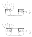
- Fig. 1 the basic structure of a lighting device 10 according to the invention is shown in a first embodiment.
- the lighting device 10 is provided for the flash photography and annular. Shown is a simplified sectional view, ie the ring is cut open, but the cut surfaces are not marked accordingly by hatched areas.
- the annular illumination device 10 is a flash-generating device (ring flash) and has a likewise annular reflector space 20 which is arranged on the annular flash so that it can be aligned in the direction of an object to be recorded.
- ring flash flash-generating device
- a flash element 40 in this case an annular flash tube, is arranged as the first light source in the reflector space 20.
- This is either stationary or variable adjustable mounted or mounted.
- point light sources 50, 51 are provided, which serve as modeling light.
- two point light sources 50, 51 are visible, whereby only one light source could be arranged. It is desirable to have a plurality of point light sources, which are then distributed uniformly around the circumference to obtain a uniform light output.
- the modeling light is used z. B. as a continuous light source.
- the reflector space 20 is lined in this embodiment with a main reflector 25 and a side reflector 26. Further, a filter element 30 is provided, the reflector space 20 in the direction of an object to be recorded (in use of the lighting device), d. h., At a radially extending outer surface, partially covering.
- the main reflector 25 is formed as an L-shaped profile and extends with the one leg on the axially extending inner side wall 24 and the other leg on the radially extending rear wall 22 of the space 20, wherein the wall 22 of the through the filter element 30th covered, radially extending outer surface 21 opposite.
- the side reflector 26 is disposed on the axially extending outer side wall 23 of the lighting device 10.
- the reflectors 25, 26 provide an increase in the light output. In addition, glare in unwanted areas can be avoided. It is also possible that the reflectors form the corresponding walls themselves. This means that the corresponding walls are formed by the reflectors or the walls are provided with a reflector layer.
- the lighting device is arranged during operation so that the reflector space faces the object to be screened.
- the side walls are understood as axial walls or as axially extending walls, lying in the ring plane walls (or surfaces, bottom surface, top surface of the hollow cylinder) as Radial walls or as radially extending walls (or surfaces).
- the surfaces are accordingly arranged substantially at 90 ° to each other.
- the filter element 30 is designed such that it only partially covers the reflector space 20 at the radially extending outer surface 21 of the reflector space and is bounded radially inward.
- a ventilation opening 60 is provided for the lighting device 10, which is designed as an opening ring.
- the point light sources 50, 51 of the modeling light are arranged in front of the ventilation opening 60 and are thus not covered by the filter element 30.
- the opening is defined to comply with minimum safety measures d.
- a forced ventilation, z As a blower, are provided (not shown here), which pushes the heat generated in the direction of arrow P from the reflector space 20.
- the filter element 30 is provided here as a UV protective glass and allows optimal protection of the object to be recorded from UV radiation.
- an electronics compartment 70 is arranged, which is provided for receiving a control circuit for the lighting device 10.
- the fan then pulls the air z. B. from the rear electronics compartment 70 and pushes them into the reflector space 20.
- the vent 60 allows the removal of the heated air.
- Fig. 2 shows a further embodiment of the device 10 according to the invention. Again, a simplified illustrated section is shown. This embodiment essentially corresponds to that in FIG Fig. 1 shown, however, here the filter element 31 is formed differently.
- the filter element 31 covers the reflector space 20 as in FIG Fig. 1 described in part, but additionally encloses the axially extending outer side wall 23 of the reflector space 20, so that the reflector space 20 and the side of UV protective glass is surrounded.
- the filter element 31 forms here (in principle with two legs), as well as the main reflector, an L-profile, wherein both L-profiles are arranged to each other such that they surround the reflector space 20.
- heated air can be derived in the direction of arrow P from the lighting device 10.
- the annular configuration of the lighting device (Ringtlash) 10 makes it possible inter alia that the device can be placed on the lens of a camera or can be arranged around the umbrella pole of a reflector screen.
- the device can filter element 30 and side reflector 26 z. B. integrally formed (s., In particular Fig. 4 ) or separable from each other or separated. In the latter case, the side reflector 26 is then completely removable, in particular in the application with the reflector screen, so that the light output can be increased over the reflector screen.
- Fig. 3 shows a further embodiment of the device 10 according to the invention in a view in the direction of the reflector space.
- the opening formed as an opening vent 61 is replaced in the filter element 32 by a plurality of distributed over the circumference openings. So the point light sources are housed protected. In addition, an intervention in the reflector space is substantially prevented.
- the ventilation openings 61 are distributed uniformly over the circumference.
- the vents may also have different sizes and / or shapes.
- Fig. 4 shows a further embodiment of the device 10 according to the invention in a cutaway view.
- This essentially corresponds to the one in Fig. 1 shown, but here side reflector 26 and protective glass 30 are firmly connected together so that they form a replaceable unit only in the whole.
- the protective glass 30 is fixed in the side reflector 26 by crimping, so that a non-removable assembly is provided. That is, the side reflector 26 is so with an edge region 27 is formed so that the protective glass in this deformed edge region 27 is receivable.
- FIGS. 5 and 6 show conventional arrangements 10 ', as known from the prior art, for example DE 10 2005 034436A1 , are known. These arrangements are annular and have a reflector space 20 'with flash tube 40' and point light sources 50 ', 51'.
- the arrangement 10 ' according to Fig. 5 shows to cover the reflector space 20 ', a protective grid 30', which serves as engagement protection, but does not prevent UV radiation.
- the grid 30 ' extends over the axially extending outer side wall of the reflector space 20' and is therefore, as well as a main reflector 25 'formed as an annular L-shaped profile. Grid and main reflector completely surround the reflector space 20 '.
- the reflector space 20 here is coated with a coating of reflective material on both the radially extending rear wall and the lateral walls, while the radially extending outer surface opposite the radially extending rear wall is covered with the grid 30'. Again, UV protection is not sufficient.
- the reflector space covers are usually designed as protective glass. So far, only completely covering filter elements are known that do not allow the dissipation of heat. Also, no point light sources can be provided in these arrangements, since the filter element would affect the light output.
- the lighting device according to the invention it is possible to work both with modeling light, as well as to provide sufficient UV protection.
- the vent (s) make it possible, using both advantages (use of modeling light, sufficient UV protection) to provide a device that can be used in all applications to obtain high image quality.
- the number of flashes that can be produced in a flash series can be increased and the object can be brought closer to the luminaire than with conventional arrangements.
Landscapes
- Physics & Mathematics (AREA)
- General Physics & Mathematics (AREA)
- Stroboscope Apparatuses (AREA)
- Non-Portable Lighting Devices Or Systems Thereof (AREA)
Description
- Die Erfindung betrifft eine Beleuchtungsvorrichtung für die Blitzlichtfotografie und Verwendungen dieser Beleuchtungsvorrichtung.
- Herkömmliche Vorrichtungen, wie z.B. aus der
DE 10 2005 034436A1 ,GB878640A GB726926A DE 1225041B bekannt, zur Bereitstellung von Licht für die Blitzlichtfotografie sind insbesondere für Blitzserien mit großer Leistung vorgesehen. Bei der Blitzerzeugung wird ein großer Anteil der elektrischen Energie in Wärme umgewandelt, so dass bei wiederholtem Blitzen die Temperatur in der Beleuchtungsvorrichtung, insbesondere im Reflektorraum schnell ansteigt. Da der Reflektorraum üblicherweise im Gebrauch in Richtung eines aufzunehmenden Objektes mittels eines Schutzglases abgedeckt ist, kann diese Wärme nur schlecht abgeführt werden. Insofern ist bei herkömmlichen Blitzleuchten nur eine limitierte Anzahl von Blitzen erzeugbar. Das Schutzglas dient insbesondere als UV-Schutz, verhindert aber, dass zusätzliche Lichtquellen, wie z. B. das zur Vorbereitung der Bildaufnahme benötigte Einstelllicht, angewendet werden können. - Blitzlichtserien mit hoher Blitzdichte bzw. eine hohe Anzahl von Blitzen, die in einer Reihe produziert werden können und die Anwendung von Einstelllicht sind aber insbesondere im Mode-, Sport- und Event-Bereich für hohe Bildqualität wichtig.
- Um nun diesen Nachteilen zu begegnen, wird anstelle des Schutzglases ein Gitter zur Abdeckung des Reflektorraums verwendet. Das Gitter ermöglicht es, dass Wärme aus dem Reflektorraum entweichen kann. Zudem ist bei Anordnungen dieser Art das erforderliche Einstelllicht einsetzbar. Allerdings ist es in diesem Falle schwierig, eine geeignete UV-Schutzmaßnahme an der Anordnung vorzusehen.
- Es ist Aufgabe der Erfindung, eine Beleuchtungsvorrichtung für die Blitzlichtfotografie anzugeben, mittels derer eine für alle Anwendungsbereiche geeignete Anordnung vorgesehen ist, insbesondere soll es ermöglicht werden, beliebig lange Blitzserien zu erzeugen und dabei einen optimalen UV-Schutz an der Beleuchtungsvorrichtung vorzusehen.
- Diese Aufgabe wird durch eine Beleuchtungsvorrichtung nach Anspruch 1 und durch entsprechende Verwendungen nach Anspruch 18 gelöst. Vorteilhafte Weiterbildungen sind in den Unteransprüchen angegeben.
- Insbesondere wird die Aufgabe durch eine Beleuchtungsvorrichtung für die Blitzlichtfotografie gelöst, die mindestens einen im Gebrauch in Richtung eines aufzunehmenden Objektes anordenbaren Reflektorraum mit mindestens einem Reflektor und mindestens ein in dem Reflektorraum angeordnetes Blitzelement als erste Lichtquelle umfasst, sowie mindestens ein, den Reflektorraum im Gebrauch in Richtung des aufzunehmenden Objektes auf einer sich radial erstreckenden Außenfläche abdeckendes UV-Filterelement, wobei das Filterelement wenigstens eine Lüftungsöffnung aufweist bzw. derart ausgebildet ist, dass eine Lüftungsöffnung vorgesehen ist.
- Ein wesentlicher Punkt der Erfindung liegt darin, dass mittels des Filterelements nun mindestens das aufzunehmende Objekt ausreichend vor UV-Strahlung geschützt ist und auch die während des Blitzens entstehende Wärme gleichzeitig durch die Lüftungsöffnung, insbesondere aus dem Reflektorraum, abführbar ist bzw. so die Lichtquellen kühlbar sind. Die Anzahl der produzierbaren Blitze in einer Blitzserie kann erhöht werden und das Objekt lässt sich näher an die Leuchte heranbringen als bei herkömmlichen Anordnungen.
- In einer Ausführungsform ist der Retlektorraum ringförmig ausgebildet und das Blitzelement ist über den Umfang (des ringförmigen Reflektorraums) verteilt angeordnet. Das heißt, die Beleuchtungsvorrichtung ist vorzugsweise ringförmig ausgebildet und erlaubt dabei die über den Umfang verteilte Anordnung des Blitzelements. Damit kann auf einen definierten Raum konzentriert eine hohe Lichtausbeute genutzt werden. Die ringförmige Ausgestaltung erlaubt es, eine zentrierte Lichtquelle vorzusehen, die hierfür an fotografischem Gerät entsprechend montiert wird. Einzelheiten zur Anwendung ringförmiger Beleuchtungsvorrichtungen werden weiter unten näher beschrieben.
- Ist die Leuchtenanordnung und damit auch der Reflektorraum ringförmig ausgebildet, so kann vorzugsweise auch das Blitzelement ringförmig ausgebildet sein. Das Blitzelement umfasst daher mindestens ein ringförmiges Blitzrohr, welches im ringförmigen Reflek-torraum entweder ortsfest oder variabel einstellbar montiert oder montierbar ist. Meist ist das Rohr fest im Reflektor eingebaut. Durch den Reflektor werden dann z. B. isoliert die zwei Leistungspole für die Zuführung der Blitzenergie geführt. Ein dritter Pol führt vorzugsweise die Zündspannung zum Zünddraht des Blitzrohres.
- Vorzugsweise ist bzw. sind im Reflektorraum mindestens eine, insbesondere mindestens drei gleichmäßig über den Umfang verteilt angeordnete Punktlichtquelle(n) als zweite Lichtquelle vorgesehen, wobei die Punktlichtquelle(n) als Einstelllicht dient bzw. dienen. Das Einstelllicht als Dauerlichtquelle ist u. a. notwendig, um beispielsweise die Beleuchtungsvorrichtung und damit das Blitzelement richtig auszurichten. Mit der erfindungsgemäßen Vorrichtung ist es nun möglich, Einstelllicht anzuwenden. Das Einstelllicht ist hierzu vorzugsweise in unmittelbarer Nähe zu der Lüftungsöffnung angeordnet, so dass die Wärme einfach abführbar ist bzw. die Lichtquellen kühlbar sind. Insbesondere erlaubt die Öffnung eine hohe Einstelllicht-Leistung, weil keine Abdeckung des Einstelllichts vorgesehen ist. Das Einstelllicht wird also nicht durch das Filterelement beeinträchtigt, d. h. die Filterwirkung tritt bezüglich des Einstelllichts nicht ein. Damit ist das Einstelllicht uneingeschränkt anwendbar.
- Vorzugsweise ist jede der Punktlichtquellen vor jeweils einer Lüftungsöffnung oder der Lüftungsöffnung angeordnet bzw. die Lüftungsöffnung(en) ist bzw. sind derart ausgebildet und angeordnet, dass sie sich vor den Einstelllicht-Punktlichtquellen befinden. Die Öffnung bzw. die Öffnungen ist bzw. sind so definiert, dass minimale Sicherheitsmaße eingehalten werden. Sicherheitsmaße sind Sicherheitsabstände, d. h. Maximalmaße, welche nicht unterschritten (ggf. auch nicht überschritten) werden dürfen, damit heiße oder elektrisch geladene Teile nicht berührt werden können. So ist z. B. ein zu beachtendes Sicherheitsmaß die höchstmögliche Breite der Lüftungsöffnung bzw. der Öffnungen.
- Eine erfindungsgemäße Weiterbildung sieht vor, dass ein Lüfter, insbesondere Gebläse vorgesehen ist, mittels dem der Reflektorraum zwangslüftbar ist, wobei die durch den Lüfter in den Reflektorraum geblasene Luft durch die im Filterelement vorgesehene Lüftungsöffnung nach außen entweichen kann. Die Vorrichtung für die Zwangsbelüftung ist dabei vorzugsweise derart anzuordnen, dass die erwärmte Luft aus dem Reflektorraum durch die Lüftungsöffnung geschoben und so die Wärme aus der Anordnung abgeführt wird.
- Vorzugsweise umfasst der Reflektorraum einen Hauptreflektor und einen Seitenreflektor, wobei der Seitenreflektor eine sich axial erstreckende äußere Seitenwand des Reflektorraumes begrenzt.
- In einer Ausführungsform sind der Seitenreflektor und das Filterelement einstückig ausgebildet, wobei zweckmäßigerweise Hauptreflektor und Seitenreflektor dann voneinander getrennt vorgesehen sind. Alternativ ist es möglich, das Filterelement auch getrennt vom Seitenreflektor vorzusehen. Das heißt, beide Elemente können getrennt voneinander nach Bedarf eingesetzt werden. Mit der ringförmigen Anordnung ist das Filterelement bevorzugt ebenfalls ringförmig ausgebildet und deckt den Reflektorraum entsprechend teilweise ab.
- Eine Ausführungsform sieht vor, dass das Filterelement als UV-Schutzglas ausgebildet ist. Das Schutzglas verhält sich optisch z. B. wie ein Diffusor für bestimmte Lichtwellenlängen. Kürzere Wellenlängen können so z. B. abgeblockt werden. Das Schutzglas hat vorzugsweise keinen Eintluss auf den Beleuchtungswinkel. Es schützt insbesondere das aufzunehmende Objekt vor UV-Strahlung.
- Sind Seitenreflektor und Filterelement, also z. B. das Schutzglas, fest miteinander verbunden, wird das Schutzglas bevorzugterweise in einen z. B. entsprechend geformten Bereich des Seitenreflektors aufgenommen. Die Verbindung entsteht vorzugsweise durch Bördeln, so dass das Schutzglas fest in dem ver- bzw. geformten Bereich des Seitenreflektors sitzt. Das heißt, der Seitenreflektor wird im Verbindungsbereich (Verbindung mit dem Schutzglas) derart um das Schutzglas geformt, dass eine feste, bevorzugt nicht demontierbare Verbindung entsteht. Dies ist eine sehr ökonomische Verbindungsmethode und führt dazu, dass das Schutzglas mit dem Seitenreflektor eine auswechselbare, nicht demontierbare Baugruppe bildet.
- In einer weiteren Ausführungsform ist dem Reflektorraum ein Elektronikraum zugeordnet, der zur Aufnahme einer Steuerschaltung für die Beleuchtungsvorrichtung dient. Der Elektronikraum ist z. B. unmittelbar benachbart (also zweckmäßigerweise z. B. "hinter") dem Reflektorraum angeordnet, um die Baugröße der Leuchtenanordnung klein zu halten. Mittels des Gebläses wird die Luft vorzugsweise vom Elektronikraum gezogen, in den Reflektorraum geschoben und zur Abfuhr der Wärme über die Lüftungsöffnung ins Freie geleitet.
- Vorteilhafterweise ist die im Filterelement vorgesehene Lüftungsöffnung als durchgehender Öffnungsring ausgebildet, welcher vorzugsweise das Filterelement nach radial innen begrenzt. Die Öffnung ist also am Innenumfang des Rings angeordnet (bzw. ist derart angeordnet, dass ein Ring ausgebildet wird) und der Reflektorraum ist damit nur teilweise abgedeckt. Unmittelbar hinter dem Öffnungsring sind dann beispielsweise die Punktlichtquellen, also das Einstelllicht, angeordnet. Diese Anordnung lässt sich einfach herstellen. Zudem sind die einzelnen Bauteile, insbesondere das Filterelement derart ausgebildet, dass es leicht handhabbar ist (vor allem im Hinblick auf den einstückig angeformten oder auch trennbar angeordneten Seitenreflektor).
- Alternativ oder auch zusätzlich ist es möglich, die im Filterelement vorgesehene Lüftungsöffnung durch eine Vielzahl vorzugsweise gleichmäßig über den Umfang verteilt angeordneter Einzelöffnungen zu definieren. Das Filterelement, also das UV-Schutzglas weist demnach einzelne Öffnungen auf, die die Lüftungsöffnung ausbilden. Die Eingriffsmöglichkeiten in den Reflektorraum sind so nahezu verhindert. Zudem ist die Konstruktion mechanisch stabiler.
- In einer vorteilhaften Ausführungsform ist der Hauptreflektor durch die mit einer reflektierenden Schicht versehene Innenseite eines ringförmigen L-Profils gebildet. Das L-Profil kleidet damit die Wände des Reflektorraumes aus, insbesondere dessen sich axial erstreckende innere Seitenwand und dessen sich radial erstreckende Rückwand. Auch der Seitenreflektor ist mit der reflektierenden Schicht ausgebildet.
- Der Seitenreflektor (für die sich axial erstreckende äußere Seitenwand) und das Filterelement für die der sich radial erstreckenden Rückwand gegenüberliegenden Fläche (sich radial erstreckende Außenfläche) umgeben den übrigen Bereich des Reflektorraumes. Möglich ist es auch, dass das Filterelement ein ringförmiges L-Profil aus UV-Schutzglas umfasst, welches derart am Hauptreflektor angeordnet ist, dass die Innenseiten von Hauptreflektor und Filterelement einander zugewandt sind. Das heißt, auch die sich axial erstreckende äußere Seitenwand ist durch das Schutzglas gebildet bzw. an dieser angeordnet, so dass sich das Filterelement letztendlich bis in den Bereich der Seitenwand erstreckt. Die aneinandergefügten L-Profile umschließen dann zusammen den Reflektorraum unter Ausbildung der oben beschriebenen Lüftungsöffnung.
- Der Elektronikraum ist an der Rückseite des sich radial nach außen erstreckenden Schenkels des ringförmigen L-Profils des Hauptreflektors angeordnet, insbesondere innerhalb eines sich ringförmig erstreckenden Elektronikgehäuses. Damit ist die Elektronik sicher und geschützt unterbringbar, wobei durch die unmittelbare Anordnung des Elektronikraums am Reflektorraum eine Platz sparende Vorrichtung bereitgestellt wird.
- Vorzugsweise ist bei Ausbildung des Filterelements als ringförmiges L-Profil aus UV-Schutzglas der sich axial oder alternativ auch radial erstreckende Schenkel durch ein(e) lichtundurchlässige(s) Band oder Ringscheibe abdeckbar. Dies ermöglicht eine zusätzliche Möglichkeit, einen sicheren UV-Schutz bereitzustellen.
- Angegeben werden weiter Verwendungen einer Beleuchtungsvorrichtung für die Blitzlichtfotografie.
- Vorzugsweise wird die beschriebene Vorrichtung für eine Kamera oder einen Reflektorschirm verwendet, wobei in erstgenanntem Fall die Beleuchtungs vorrichtung sich vorzugsweise um ein Objektiv und in zweitgenanntem Fall sich um einen Schirmstock herumerstreckend anordenbar ist.
- Für die Anwendung mit dem Reflektorschirm ist es von Vorteil, den Seitenreflektor zu entfernen und den Schirmreflektor zu nutzen. Hierzu ist z. B. das L-förmige Filterelementprofil vorgesehen. Durch diese bevorzugten Verwendungen können verschiedene fotographische Instrumente mit der Beleuchtungsvorrichtung auf einfache Art mit besserer Ausleuchtung als bisher betrieben werden.
- Nachfolgend wird die Erfindung anhand von Ausführungsbeispielen beschrieben, die anhand der Abbildungen näher erläutert werden. Hierbei zeigen:
- - Fig. 1
- eine Ausführungsform der erfindungsgemäßen Beleuchtungsvorrichtung in einer vereinfachten Schnittdarstellung;
- - Fig. 2
- eine weitere Ausführungsform der erfindungsgemäßen Vorrichtung in einer vereinfachten Schnittdarstellung;
- - Fig. 3
- eine weitere Ausführungsform der erfindungsgemäßen Vorrichtung in einer Ansicht in Richtung auf den Reflektorraum;
- - Fig. 4
- eine weitere Ausführungsform der erfindungsgemäßen Vorrichtung in einer aufgeschnittenen Darstellung;
- - Fig. 5
- eine Darstellung zum Stand der Technik;
- - Fig. 6
- eine weitere Darstellung zum Stand der Technik.
- In der nachfolgenden Beschreibung werden für gleiche und gleich wirkende Teile dieselben Bezugsziffern verwendet.
- In
Fig. 1 ist der prinzipielle Aufbau einer erfindungsgemäßen Beleuchtungsvorrichtung 10 in einer ersten Ausführungsform gezeigt. Die Beleuchtungsvorrichtung 10 ist für die Blitzlichtfotografie vorgesehen und ringförmig ausgebildet. Dargestellt ist eine vereinfachte Schnittdarstellung, d. h. der Ring ist aufgeschnitten, wobei jedoch die Schnittflächen nicht entsprechend durch schraffierte Bereiche gekennzeichnet sind. - Die ringförmige Beleuchtungsvorrichtung 10 ist eine Blitz erzeugende Vorrichtung (Ringflash) und weist einen ebenfalls ringförmigen Reflektorraum 20 auf, der derart an dem Ringflash angeordnet ist, dass er in Richtung eines aufzunehmenden Objektes ausgerichtet werden kann.
- In dem Reflektorraum 20 ist ein Blitzelement 40, in diesem Falle ein ringförmiges Blitzrohr als erste Lichtquelle angeordnet. Dieses ist entweder ortsfest oder variabel einstellbar montiert bzw. montierbar. Ferner sind Punktlichtquellen 50, 51 vorgesehen, die als Einstelllicht dienen. Hier sind zwei Punktlichtquellen 50, 51 sichtbar, wobei auch lediglich eine Lichtquelle angeordnet sein könnte. Wünschenswert ist eine Vielzahl von Punktlichtquellen, die dann gleichmäßig über den Umfang verteilt angeordnet sind, um eine gleichmäßige Lichtausbeute zu erhalten. Das Einstelllicht dient z. B. als Dauerlichtquelle.
- Der Reflektorraum 20 ist in diesem Ausführungsbeispiel mit einem Hauptreflektor 25 und einem Seitenreflektor 26 ausgekleidet. Ferner ist ein Filterelement 30 vorgesehen, das den Reflektorraum 20 in Richtung eines aufzunehmenden Objektes (im Gebrauch der Beleuchtungsvorrichtung), d. h., an einer sich radial erstreckenden Außenfläche, teilweise abdeckt. Der Hauptreflektor 25 ist als L-förmiges Profil ausgebildet und erstreckt sich mit dem einen Schenkel über die sich axial erstreckende innere Seitenwand 24 und mit dem anderen Schenkel über die sich radial erstreckende Rückwand 22 des Raumes 20, wobei die Wand 22 der durch das Filterelement 30 abgedeckten, sich radial erstreckenden Außenfläche 21 gegenüberliegt. Der Seitenreflektor 26 ist an der sich axial erstreckenden äußeren Seitenwand 23 der Beleuchtungsvorrichtung 10 angeordnet. Die Reflektoren 25, 26 sorgen für eine Erhöhung der Lichtausbeute. Zudem lassen sich Blendungen in unerwünschten Bereichen vermeiden. Möglich ist es auch, dass die Reflektoren die entsprechenden Wände selbst ausbilden. Das heißt also, dass die entsprechenden Wände durch die Reflektoren gebildet werden oder aber die Wände sind mit einer Reflektorschicht versehen.
- Die Beleuchtungsvorrichtung wird während des Betriebes so angeordnet, dass der Reflektorraum dem abzulichtenden Objekt zugewandt ist. Die Seitenwände (Mantelflächen bzw. Mantelfläche und innen liegende, sich parallel zur Mantelfläche erstreckende Fläche des Hohlzylinders) werden als axiale Wände bzw. als sich axial erstreckende Wände verstanden, die in Ringebene liegenden Wände (bzw. Flächen; Bodenfläche, Deckfläche des Hohlzylinders) als radiale Wände bzw. als sich radial erstreckende Wände (bzw. Flächen). Die Flächen sind demgemäß im Wesentlichen im 90°-Winkel zueinander angeordnet.
- Das Filterelement 30 ist derart ausgebildet, dass es den Reflektorraum 20 an der sich radial erstreckenden Außenfläche 21 des Reflektorraumes nur teilweise abdeckt und nach radial innen begrenzt ist. Damit wird eine Lüftungsöffnung 60 für die Beleuchtungsvorrichtung 10 bereitgestellt, die als Öffnungsring ausgebildet ist.
- Da während der Erzeugung von Blitzen Wärme entsteht, lässt sich diese über die Lüftungsöffnung 60 in Pfeilrichtung P abführen. Die Punktlichtquellen 50, 51 des Einstelllichts sind vor der Lüftungsöffnung 60 angeordnet und werden so nicht von dem Filterelement 30 abgedeckt. Im Übrigen ist die Öffnung so definiert, dass minimale Sicherheitsmaße d eingehalten werden.
- Aufgrund der Lüftungsöffnung ist es möglich, eine hohe Anzahl an Blitzen in einer Serie zu erzeugen, da die produzierte Wärme einfach ableitbar ist und die Lichtquellen so auch kühlbar sind. Vorzugsweise kann eine Zwangsbelüftung, z. B. ein Gebläse, vorgesehen werden (hier nicht gezeigt), das die erzeugte Wärme in Pfeilrichtung P aus dem Reflektorraum 20 schiebt.
- Das Filterelement 30 ist hier als UV-Schutzglas vorgesehen und erlaubt einen optimalen Schutz des aufzunehmenden Objekts vor UV-Strahlung.
- Unmittelbar an die sich radial erstreckende Rückwand 22 des Reflektorraumes 20 anschließend ist ein Elektronikraum 70 angeordnet, der zur Aufnahme einer Steuerschaltung für die Beleuchtungsvorrichtung 10 vorgesehen ist. Das Gebläse zieht die Luft dann z. B. vom hinteren Elektronikraum 70 und schiebt sie in den Reflektorraum 20. Die Lüftungsöffnung 60 erlaubt die Entfernung der erwärmten Luft.
-
Fig. 2 zeigt eine weitere Ausführungsform der erfindungsgemäßen Vorrichtung 10. Auch hier ist ein vereinfacht dargestellter Schnitt gezeigt. Diese Ausführungsform entspricht im Wesentlichen der inFig. 1 gezeigten, allerdings ist hier das Filterelement 31 unterschiedlich ausgebildet. Das Filterelement 31 deckt den Reflektorraum 20 wie inFig. 1 beschrieben teilweise ab, umschließt jedoch zusätzlich die sich axial erstreckende äußere Seitenwand 23 des Reflektorraumes 20, so dass der Reflektorraum 20 auch seitlich von UV-Schutzglas umgeben ist. Das Filterelement 31 bildet hier (im Prinzip mit zwei Schenkeln), ebenso wie der Hauptreflektor, ein L-Profil aus, wobei beide L-Profile derart zueinander angeordnet sind, dass sie den Reflektorraum 20 umschließen. - Auch in diesem Falle lässt sich erwärmte Luft in Pfeilrichtung P aus der Beleuchtungsvorrichtung 10 ableiten.
- Die ringförmige Ausgestaltung der Beleuchtungsvorrichtung (Ringtlash) 10 ermöglicht es u. a., dass die Vorrichtung auf das Objektiv einer Kamera aufsetzbar oder sich um den Schirmstock eines Reflektorschirms herumerstreckend anordenbar ist. Bei der Ausführungsform gemäß
Fig. 1 können Filterelement 30 und Seitenreflektor 26 z. B. einstückig ausgebildet sein (s. insbesondereFig. 4 ) oder aber voneinander trennbar bzw. getrennt. In letzterem Fall ist der Seitenreflektor 26 dann, insbesondere in der Anwendung mit dem Reflektorschirm, vollständig entfernbar, so dass über den Reflektorschirm die Lichtausbeute erhöht werden kann. -
Fig. 3 zeigt eine weitere Ausführungsform der erfindungsgemäßen Vorrichtung 10 in einer Ansicht in Richtung auf den Reflektorraum. Hier ist die als Öffnungsring ausgebildete Lüftungsöffnung 61 in dem Filterelement 32 durch eine Vielzahl an über den Umfang verteilte Öffnungen ersetzt. So sind die Punktlichtquellen geschützter untergebracht. Zudem wird ein Eingriff in den Reflektorraum im Wesentlichen verhindert. In dieser Ausführungsform sind die Lüftungsöffnungen 61 gleichmäßig über den Umfang verteilt. Möglich ist es natürlich auch, eine andere, nicht gleichmäßige Verteilung vorzugeben, um möglichst viele Lüftungsöffnungen dort vorzusehen, wo die größte Temperaturerhöhung in dem Reflektorraum zu erwarten ist. Die Lüftungsöffnungen können ebenso unterschiedliche Größen und/oder Formen aufweisen. -
Fig. 4 zeigt eine weitere Ausführungsform der erfindungsgemäßen Vorrichtung 10 in aufgeschnittener Darstellung. Diese entspricht im Wesentlichen der inFig. 1 gezeigten, allerdings sind hier Seitenreflektor 26 und Schutzglas 30 fest miteinander verbunden, so dass sie eine nur im Gesamten austauschbare Einheit bilden. In dieser Ausführungsform ist das Schutzglas 30 im Seitenreflektor 26 durch Bördeln befestigt, so dass eine nicht demontierbare Baugruppe vorgesehen ist. Das heißt, der Seitenreflektor 26 ist derart mit einem Randbereich 27 ausgebildet, dass das Schutzglas in diesen verformten Randbereich 27 aufnehmbar ist. - Die
Fig. 5 und 6 zeigen herkömmliche Anordnungen 10', wie sie aus dem Stand der Technik z.B. derDE 10 2005 034436A1 , bekannt sind. Auch diese Anordnungen sind ringförmig ausgebildet und weisen einen Reflektorraum 20' mit Blitzrohr 40' und Punktlichtquellen 50', 51' auf. - Die Anordnung 10' gemäß
Fig. 5 zeigt zur Abdeckung des Reflektorraums 20' ein Schutzgitter 30', das als Eingriffsschutz dient, jedoch keine UV-Strahlung abhält. Das Gitter 30' zieht sich über die sich axial erstreckende äußere Seitenwand des Reflektorraums 20' und ist daher, ebenso wie ein Hauptreflektor 25' als ringförmiges L-Profil ausgebildet. Gitter und Hauptreflektor umschließen den Reflektorraum 20' vollständig. - Wie mit
Fig. 6 gezeigt, ist der Reflektorraum 20' hier sowohl an der sich radial erstreckenden Rückwand als auch an den seitlichen Wänden mit einer Beschichtung aus reflektierendem Material ausgekleidet, während die der sich radial erstreckenden Rückwand gegenüberliegende sich radial erstreckende Außenfläche mit dem Gitter 30' abgedeckt ist. Auch hier ist ein UV-Schutz nicht ausreichend gegeben. - Um den UV-Schutz auch bei herkömmlichen Anordnungen zu realisieren, sind die Reflektorraumabdeckungen meist als Schutzglas ausgebildet. Bekannt sind bisher nur vollständig abdeckende Filterelemente, die keine Abfuhr von Wärme zulassen. Auch können bei diesen Anordnungen keine Punktlichtquellen vorgesehen werden, da das Filterelement die Lichtausbeute beeinträchtigen würde.
- Mit der erfindungsgemäßen Beleuchtungsvorrichtung ist es möglich, sowohl mit Einstelllicht zu arbeiten, als auch einen ausreichenden UV-Schutz vorzusehen. Die Lüftungsöffnung(en) ermöglichen es, unter Ausnutzung beider Vorteile (Anwendung von Einstelllicht, ausreichender UV-Schutz) eine Vorrichtung bereitzustellen, die in allen Anwendungsbereichen zur Erlangung hoher Bildqualität einsetzbar ist. Die Anzahl der produzierbaren Blitze in einer Blitzserie kann erhöht werden und das Objekt lässt sich näher an die Leuchte heranbringen als bei herkömmlichen Anordnungen.
-
- 10
- Beleuchtungsvorrichtung
- 20
- Reflektorraum
- 21
- Sich radial erstreckende Außenfläche
- 22
- Sich radial erstreckende Rückwand
- 23
- Sich axial erstreckende äußere Seitenwand
- 24
- Sich axial erstreckende innere Seitenwand
- 25
- Hauptreflektor
- 26
- Seitenreflektor
- 27
- Randbereich
- 30
- Filterelement
- 31
- Filterelement
- 32
- Filterelement
- 40
- Blitzelement, Blitzrohr
- 50
- Punktlichtquelle, Einstelllicht
- 51
- Punktlichtquelle, Einstelllicht
- 60
- Lüftungsöffnung
- 61
- Lüftungsöffnung
- 70
- Elektronikraum
- 10'
- Beleuchtungsvorrichtung
- 20'
- Reflektorraum
- 25'
- Hauptreflektor
- 30'
- Schutzgitter
- 40'
- Blitzelement, Blitzrohr
- 50'
- Punktlichtquelle, Einstelllicht
- 51'
- Punktlichtquelle, Einstelllicht
- P
- Pfeilrichtung (Luftstrom)
- d
- Sicherheitsabstand
Claims (18)
- Beleuchtungsvorrichtung (10) für die Blitzlichtfotografie, umfassend- mindestens einen im Gebrauch in Richtung eines aufzunehmenden Objektes anordenbaren Reflektorraum (20) mit mindestens einem Reflektor (25),- mindestens ein in dem Reflektorraum (20) angeordnetes Blitzelement (40) als erste Lichtquelle,- mindestens ein, den Reflektorraum (20) im Gebrauch in Richtung des aufzunehmenden Objektes auf einer sich radial erstreckenden Außenfläche (21) abdeckendes UV-Filterelement (30, 31, 32), dadurch gekennzeichnet, dass das Filterelement (30, 31, 32) wenigstens eine Lüftungsöffnung (60, 61) aufweist.
- Beleuchtungsvorrichtung nach Anspruch 1,
dadurch gekennzeichnet, dass
der Reflektorraum (20) ringförmig ausgebildet und das Blitzelement (40) über den Umfang verteilt angeordnet ist. - Beleuchtungsvorrichtung nach Anspruch 1 oder 2,
dadurch gekennzeichnet, dass
das Blitzelement (20) mindestens ein ringförmiges Blitzrohr umfasst, welches im ringförmigen Reflektorraum (20) entweder ortsfest oder variabel einstellbar montiert oder montierbar ist. - Beleuchtungsvorrichtung nach einem der vorhergehenden Ansprüche,
dadurch gekennzeichnet, dass
im Reflektorraum (20) mindestens eine, insbesondere mindestens drei gleichmäßig über den Umfang verteilt angeordnete Punktlichtquelle(n) (50, 51) als zweite Lichtquelle vorgesehen ist bzw. sind, wobei die Punktlichtquelle(n) (50, 51) als Einstelllicht dient bzw. dienen. - Beleuchtungsvorrichtung nach Anspruch 4,
dadurch gekennzeichnet, dass
jede der Punktlichtquellen (50, 51) vor jeweils einer Lüftungsöffnung (60, 61) angeordnet ist. - Beleuchtungsvorrichtung nach einem der vorhergehenden Ansprüche,
dadurch gekennzeichnet, dass
ein Lüfter, insbesondere Gebläse vorgesehen ist, mittels dem der Reflektorraum (20) zwangslüftbar ist, wobei die durch den Lüfter in den Reflektorraum (20) geblasene Luft durch die im Filterelement (30, 31, 32) vorgesehene Lüftungsöffnung (60, 61) nach außen entweichen kann. - Beleuchtungsvorrichtung nach einem der vorhergehenden Ansprüche,
dadurch gekennzeichnet, dass
der Reflektorraum (20) einen Hauptreflektor (25) und einen Seitenreflektor (26) umfasst, wobei der Seitenreflektor (26) eine sich axial erstreckende äußere Seitenwand (23) des Reflektorraumes (20) begrenzt. - Beleuchtungsvorrichtung nach Anspruch 7,
dadurch gekennzeichnet, dass
der Seitenreflektor (26) und das Filterelement (30, 32) einstückig ausgebildet sind. - Beleuchtungsvorrichtung nach Anspruch 7 oder 8,
dadurch gekennzeichnet, dass
das UV-Filterelement (30, 32) vom Seitenreflektor (26) trennbar ist. - Beleuchtungsvorrichtung nach einem der vorhergehenden Ansprüche,
dadurch gekennzeichnet, dass
das UV-Filterelement (30, 31, 32) als UV-Schutzglas ausgebildet ist. - Beleuchtungsvorrichtung nach einem der vorhergehenden Ansprüche,
dadurch gekennzeichnet, dass
dem Reflektorraum (20) ein Elektronikraum (70) zugeordnet ist, der zur Aufnahme einer Steuerschaltung für die Beleuchtungsvorrichtung (10) dient. - Beleuchtungsvorrichtung nach einem der vorhergehenden Ansprüche,
dadurch gekennzeichnet, dass
die im UV-Filterelement (30, 31) vorgesehene Lüftungsöffnung (60) als durchgehender Öffnungsring ausgebildet ist, welcher vorzugsweise das Filterelement (30, 31) nach radial innen begrenzt. - Beleuchtungsvorrichtung nach einem der vorhergehenden Ansprüche,
dadurch gekennzeichnet, dass
die im UV-Filterelement (32) vorgesehene Lüftungsöffnung durch eine Vielzahl vorzugsweise gleichmäßig über den Umfang verteilt angeordneter Einzelöffnungen (61) definiert ist. - Beleuchtungsvorrichtung nach einem der Ansprüche 7, 8 oder 9,
dadurch gekennzeichnet, dass
der Hauptreflektor (25) durch die mit einer reflektierenden Schicht versehene Innenseite eines ringförmigen L-Profils gebildet ist. - Beleuchtungsvorrichtung nach einem der Ansprüche 7, 8, 9 oder 14,
dadurch gekennzeichnet, dass
das UV-Filterelement (31, 32) ein ringförmiges L-Profil aus UV-Schutzglas umfasst, welches derart am Hauptreflektor (25) angeordnet ist, dass die Innenseiten von Hauptreflektor (25) und Filterelement (31, 32) einander zugewandt sind. - Beleuchtungsvorrichtung nach einem der Ansprüche 7, 8, 9, 14 oder 15 in Verbindung mit Anspruch 11,
dadurch gekennzeichnet, dass
der Elektronikraum (70) an der Rückseite des sich radial nach außen erstreckenden Schenkels des ringförmigen L-Profils des Hauptreflektors (25) angeordnet ist, insbesondere innerhalb eines sich ringförmig erstreckenden Elektronikgehäuses. - Beleuchtungsvorrichtung nach einem der vorhergehenden Ansprüche,
dadurch gekennzeichnet, dass
bei Ausbildung des UV-Filterelements (31, 32) als ringförmiges L-Profil aus UV-Schutzglas der sich axial oder alternativ auch radial erstreckende Schenkel durch ein(e) lichtundurchlässige(s) Band oder Ringscheibe abdeckbar ist. - Verwendung einer Beleuchtungsvorrichtung nach einem der vorhergehenden Ansprüche für eine Kamera oder eine Reflektorschirm, wobei in erstgenanntem Fall die Beleuchtungsvorrichtung (10) sich vorzugsweise um ein Objektiv und in zweitgenanntem Fall sich um einen Schirmstock herumerstreckend anordenbar ist.
Applications Claiming Priority (2)
| Application Number | Priority Date | Filing Date | Title |
|---|---|---|---|
| DE102007033455A DE102007033455B4 (de) | 2007-07-18 | 2007-07-18 | Beleuchtungsvorrichtung für die Blitzlichtfotografie |
| PCT/EP2008/059414 WO2009010571A1 (de) | 2007-07-18 | 2008-07-17 | Beleuchtungsvorrichtung für die blitzlichtfotografie |
Publications (2)
| Publication Number | Publication Date |
|---|---|
| EP2168006A1 EP2168006A1 (de) | 2010-03-31 |
| EP2168006B1 true EP2168006B1 (de) | 2012-09-12 |
Family
ID=39735340
Family Applications (1)
| Application Number | Title | Priority Date | Filing Date |
|---|---|---|---|
| EP08775193A Not-in-force EP2168006B1 (de) | 2007-07-18 | 2008-07-17 | Beleuchtungsvorrichtung für die Blitzlichtfotografie |
Country Status (4)
| Country | Link |
|---|---|
| US (1) | US8128247B2 (de) |
| EP (1) | EP2168006B1 (de) |
| DE (2) | DE102007033455B4 (de) |
| WO (1) | WO2009010571A1 (de) |
Families Citing this family (7)
| Publication number | Priority date | Publication date | Assignee | Title |
|---|---|---|---|---|
| CA2787266C (en) * | 2010-01-14 | 2016-03-08 | Infection Prevention Technologies | Systems and methods for emitting radiant energy |
| US10288983B2 (en) * | 2016-04-26 | 2019-05-14 | Lumileds Llc | LED flash ring surrounding camera lens |
| TWI760955B (zh) | 2016-04-26 | 2022-04-11 | 荷蘭商露明控股公司 | 環繞攝影機透鏡之發光二極體閃光環及提供照明之方法 |
| US10274811B2 (en) * | 2017-02-17 | 2019-04-30 | Lifetouch Inc. | Edge light device for photography system |
| USD852260S1 (en) | 2017-02-17 | 2019-06-25 | Lifetouch Inc. | Photographic lighting apparatus |
| CN109764285B (zh) * | 2019-03-29 | 2023-10-24 | 杭州涂鸦信息技术有限公司 | 智能探照灯 |
| DE102019135534B4 (de) * | 2019-12-20 | 2024-05-23 | Hans-Werner Friedrich Briese | Leuchteneinheit, Beleuchtungseinrichtung mit einer Leuchteneinheit und Reflektoranordnung mit einer Beleuchtungseinrichtung |
Family Cites Families (11)
| Publication number | Priority date | Publication date | Assignee | Title |
|---|---|---|---|---|
| GB726926A (en) * | 1952-05-22 | 1955-03-23 | Winston Electronics Ltd | Improvements in or relating to electronic flash light photography |
| US2979601A (en) * | 1957-11-20 | 1961-04-11 | John V Mcclees | Photographic flash attachment |
| CH355028A (de) * | 1958-01-30 | 1961-06-15 | Bron & Co | Elektronenblitzlampe für die photographische Reproduktion von Durchsichtsbildern |
| DE1225041B (de) | 1964-07-16 | 1966-09-15 | Multiblitz Geraete Dr Ing D A | Vorrichtung zur photographischen Belichtung, vorzugsweise fuer Vergroesserungsgeraete |
| DE4006009A1 (de) * | 1989-02-28 | 1990-08-30 | Metz Werke Gmbh & Co Kg | Abdeckvorrichtung fuer die lichtaustrittsoeffnung eines blitzgeraetes |
| US5093769A (en) * | 1990-10-04 | 1992-03-03 | Luntsford K Paul | Surgical lighting system |
| DE9017143U1 (de) * | 1990-12-19 | 1991-03-07 | Delma, Elektro- Und Medizinische Apparatebaugesellschaft Mbh, 7200 Tuttlingen | Operationsleuchte |
| US6022124A (en) * | 1997-08-19 | 2000-02-08 | Ppt Vision, Inc. | Machine-vision ring-reflector illumination system and method |
| EP1177411A1 (de) * | 1999-05-10 | 2002-02-06 | Schröter, Michael | Verbrauchszähler und verfahren zum ablesen eines ortsfesten verbrauchszählers |
| US6749310B2 (en) * | 2001-09-07 | 2004-06-15 | Contrast Lighting Services, Inc. | Wide area lighting effects system |
| DE102005034436A1 (de) * | 2005-07-14 | 2007-01-25 | Bron Elektronik Ag | Ringleuchte |
-
2007
- 2007-07-18 DE DE102007033455A patent/DE102007033455B4/de not_active Expired - Fee Related
-
2008
- 2008-07-17 EP EP08775193A patent/EP2168006B1/de not_active Not-in-force
- 2008-07-17 DE DE202008017233U patent/DE202008017233U1/de not_active Expired - Lifetime
- 2008-07-17 WO PCT/EP2008/059414 patent/WO2009010571A1/de not_active Ceased
- 2008-07-17 US US12/669,210 patent/US8128247B2/en not_active Expired - Fee Related
Also Published As
| Publication number | Publication date |
|---|---|
| US20100265690A1 (en) | 2010-10-21 |
| DE102007033455A1 (de) | 2009-01-22 |
| WO2009010571A1 (de) | 2009-01-22 |
| DE202008017233U1 (de) | 2009-04-30 |
| EP2168006A1 (de) | 2010-03-31 |
| DE102007033455B4 (de) | 2009-06-25 |
| US8128247B2 (en) | 2012-03-06 |
Similar Documents
| Publication | Publication Date | Title |
|---|---|---|
| DE102007033455B4 (de) | Beleuchtungsvorrichtung für die Blitzlichtfotografie | |
| DE102014209320B4 (de) | Fahrzeugleuchte | |
| EP2793066B1 (de) | Ringbeleuchtungsvorrichtung für ein Mikroskopobjektiv und Mikroskopobjektiv | |
| EP2332490B1 (de) | Lichthärtgerät für Dentalzwecke | |
| EP2871411B2 (de) | Optisches Element für eine Leuchte, sowie Leuchte | |
| EP3008381B1 (de) | Led-modul mit berührungsschutzelement | |
| DE202014008377U1 (de) | Lampenvorrichtung mit der Möglichkeit zur Veränderung eines räumlichen Lichtausstrahlwinkels | |
| DE2618310C3 (de) | Strahlerleuchte | |
| DE3640334C2 (de) | ||
| DE19603025C2 (de) | Beleuchtungsvorrichtung zur Einspeisung von Licht in Lichtleitfasern | |
| EP1915569B1 (de) | Kühlsystem für einen scheinwerfer | |
| EP3657066A1 (de) | Beleuchtungseinheit für einen kraftfahrzeugscheinwerfer zum erzeugen einer lichtverteilung mit hell-dunkel-grenze | |
| DE102018114615A1 (de) | Temperaturkalibrator | |
| DE10101005B4 (de) | Kraftfahrzeugleuchte, insbesondere Scheinwerfer | |
| DE102016121369A1 (de) | Rauchmesszelle | |
| DE102013210856A1 (de) | Leuchte für ein Kraftfahrzeug | |
| DE202017105033U1 (de) | Licht emittierende Vorrichtung | |
| DE102005054031B4 (de) | Hochleistungsleuchte mit Kühlmantel | |
| DE102013101692A1 (de) | Unterwasserscheinwerfer und Sicherheitssystem | |
| DE102011115037A1 (de) | Leuchte mit einem LED-Leuchtmittel | |
| EP4528148A1 (de) | Leuchte mit lichtleiterunterstützter lichtabgabe | |
| EP3587898B1 (de) | Gehäuse | |
| DE102011080809A1 (de) | LED-Leuchte | |
| DE1115656B (de) | Reflektoranordnung fuer langgestreckte, roehrenfoermige Lichtquellen | |
| DE202013002706U1 (de) | Außenleuchte und Abschirmung für eine Außenleuchte |
Legal Events
| Date | Code | Title | Description |
|---|---|---|---|
| PUAI | Public reference made under article 153(3) epc to a published international application that has entered the european phase |
Free format text: ORIGINAL CODE: 0009012 |
|
| 17P | Request for examination filed |
Effective date: 20090316 |
|
| AK | Designated contracting states |
Kind code of ref document: A1 Designated state(s): AT BE BG CH CY CZ DE DK EE ES FI FR GB GR HR HU IE IS IT LI LT LU LV MC MT NL NO PL PT RO SE SI SK TR |
|
| AX | Request for extension of the european patent |
Extension state: AL BA MK RS |
|
| RIN1 | Information on inventor provided before grant (corrected) |
Inventor name: GRIESSMANN, MARCEL Inventor name: PORTMANN, FRANCOIS |
|
| DAX | Request for extension of the european patent (deleted) | ||
| REG | Reference to a national code |
Ref country code: DE Ref legal event code: R079 Ref document number: 502008008177 Country of ref document: DE Free format text: PREVIOUS MAIN CLASS: G03B0015020000 Ipc: G03B0015050000 |
|
| RIC1 | Information provided on ipc code assigned before grant |
Ipc: F21V 9/06 20060101ALI20111202BHEP Ipc: G03B 15/05 20060101AFI20111202BHEP |
|
| RTI1 | Title (correction) |
Free format text: ILLUMINATION DEVICE FOR FLASH PHOTOGRAPHY |
|
| GRAP | Despatch of communication of intention to grant a patent |
Free format text: ORIGINAL CODE: EPIDOSNIGR1 |
|
| GRAS | Grant fee paid |
Free format text: ORIGINAL CODE: EPIDOSNIGR3 |
|
| GRAA | (expected) grant |
Free format text: ORIGINAL CODE: 0009210 |
|
| AK | Designated contracting states |
Kind code of ref document: B1 Designated state(s): AT BE BG CH CY CZ DE DK EE ES FI FR GB GR HR HU IE IS IT LI LT LU LV MC MT NL NO PL PT RO SE SI SK TR |
|
| REG | Reference to a national code |
Ref country code: GB Ref legal event code: FG4D Free format text: NOT ENGLISH |
|
| REG | Reference to a national code |
Ref country code: CH Ref legal event code: EP |
|
| REG | Reference to a national code |
Ref country code: AT Ref legal event code: REF Ref document number: 575335 Country of ref document: AT Kind code of ref document: T Effective date: 20120915 |
|
| REG | Reference to a national code |
Ref country code: CH Ref legal event code: NV Representative=s name: TROESCH SCHEIDEGGER WERNER AG |
|
| REG | Reference to a national code |
Ref country code: IE Ref legal event code: FG4D Free format text: LANGUAGE OF EP DOCUMENT: GERMAN |
|
| REG | Reference to a national code |
Ref country code: DE Ref legal event code: R096 Ref document number: 502008008177 Country of ref document: DE Effective date: 20121108 |
|
| REG | Reference to a national code |
Ref country code: SE Ref legal event code: TRGR |
|
| PG25 | Lapsed in a contracting state [announced via postgrant information from national office to epo] |
Ref country code: CY Free format text: LAPSE BECAUSE OF FAILURE TO SUBMIT A TRANSLATION OF THE DESCRIPTION OR TO PAY THE FEE WITHIN THE PRESCRIBED TIME-LIMIT Effective date: 20120912 Ref country code: HR Free format text: LAPSE BECAUSE OF FAILURE TO SUBMIT A TRANSLATION OF THE DESCRIPTION OR TO PAY THE FEE WITHIN THE PRESCRIBED TIME-LIMIT Effective date: 20120912 Ref country code: NO Free format text: LAPSE BECAUSE OF FAILURE TO SUBMIT A TRANSLATION OF THE DESCRIPTION OR TO PAY THE FEE WITHIN THE PRESCRIBED TIME-LIMIT Effective date: 20121212 Ref country code: FI Free format text: LAPSE BECAUSE OF FAILURE TO SUBMIT A TRANSLATION OF THE DESCRIPTION OR TO PAY THE FEE WITHIN THE PRESCRIBED TIME-LIMIT Effective date: 20120912 Ref country code: LT Free format text: LAPSE BECAUSE OF FAILURE TO SUBMIT A TRANSLATION OF THE DESCRIPTION OR TO PAY THE FEE WITHIN THE PRESCRIBED TIME-LIMIT Effective date: 20120912 |
|
| REG | Reference to a national code |
Ref country code: NL Ref legal event code: VDEP Effective date: 20120912 |
|
| REG | Reference to a national code |
Ref country code: LT Ref legal event code: MG4D Effective date: 20120912 |
|
| PG25 | Lapsed in a contracting state [announced via postgrant information from national office to epo] |
Ref country code: SI Free format text: LAPSE BECAUSE OF FAILURE TO SUBMIT A TRANSLATION OF THE DESCRIPTION OR TO PAY THE FEE WITHIN THE PRESCRIBED TIME-LIMIT Effective date: 20120912 Ref country code: GR Free format text: LAPSE BECAUSE OF FAILURE TO SUBMIT A TRANSLATION OF THE DESCRIPTION OR TO PAY THE FEE WITHIN THE PRESCRIBED TIME-LIMIT Effective date: 20121213 Ref country code: LV Free format text: LAPSE BECAUSE OF FAILURE TO SUBMIT A TRANSLATION OF THE DESCRIPTION OR TO PAY THE FEE WITHIN THE PRESCRIBED TIME-LIMIT Effective date: 20120912 |
|
| PG25 | Lapsed in a contracting state [announced via postgrant information from national office to epo] |
Ref country code: EE Free format text: LAPSE BECAUSE OF FAILURE TO SUBMIT A TRANSLATION OF THE DESCRIPTION OR TO PAY THE FEE WITHIN THE PRESCRIBED TIME-LIMIT Effective date: 20120912 Ref country code: ES Free format text: LAPSE BECAUSE OF FAILURE TO SUBMIT A TRANSLATION OF THE DESCRIPTION OR TO PAY THE FEE WITHIN THE PRESCRIBED TIME-LIMIT Effective date: 20121223 Ref country code: RO Free format text: LAPSE BECAUSE OF FAILURE TO SUBMIT A TRANSLATION OF THE DESCRIPTION OR TO PAY THE FEE WITHIN THE PRESCRIBED TIME-LIMIT Effective date: 20120912 Ref country code: CZ Free format text: LAPSE BECAUSE OF FAILURE TO SUBMIT A TRANSLATION OF THE DESCRIPTION OR TO PAY THE FEE WITHIN THE PRESCRIBED TIME-LIMIT Effective date: 20120912 Ref country code: IS Free format text: LAPSE BECAUSE OF FAILURE TO SUBMIT A TRANSLATION OF THE DESCRIPTION OR TO PAY THE FEE WITHIN THE PRESCRIBED TIME-LIMIT Effective date: 20130112 Ref country code: NL Free format text: LAPSE BECAUSE OF FAILURE TO SUBMIT A TRANSLATION OF THE DESCRIPTION OR TO PAY THE FEE WITHIN THE PRESCRIBED TIME-LIMIT Effective date: 20120912 |
|
| PG25 | Lapsed in a contracting state [announced via postgrant information from national office to epo] |
Ref country code: PT Free format text: LAPSE BECAUSE OF FAILURE TO SUBMIT A TRANSLATION OF THE DESCRIPTION OR TO PAY THE FEE WITHIN THE PRESCRIBED TIME-LIMIT Effective date: 20130114 Ref country code: PL Free format text: LAPSE BECAUSE OF FAILURE TO SUBMIT A TRANSLATION OF THE DESCRIPTION OR TO PAY THE FEE WITHIN THE PRESCRIBED TIME-LIMIT Effective date: 20120912 Ref country code: SK Free format text: LAPSE BECAUSE OF FAILURE TO SUBMIT A TRANSLATION OF THE DESCRIPTION OR TO PAY THE FEE WITHIN THE PRESCRIBED TIME-LIMIT Effective date: 20120912 |
|
| PLBE | No opposition filed within time limit |
Free format text: ORIGINAL CODE: 0009261 |
|
| STAA | Information on the status of an ep patent application or granted ep patent |
Free format text: STATUS: NO OPPOSITION FILED WITHIN TIME LIMIT |
|
| PG25 | Lapsed in a contracting state [announced via postgrant information from national office to epo] |
Ref country code: DK Free format text: LAPSE BECAUSE OF FAILURE TO SUBMIT A TRANSLATION OF THE DESCRIPTION OR TO PAY THE FEE WITHIN THE PRESCRIBED TIME-LIMIT Effective date: 20120912 Ref country code: BG Free format text: LAPSE BECAUSE OF FAILURE TO SUBMIT A TRANSLATION OF THE DESCRIPTION OR TO PAY THE FEE WITHIN THE PRESCRIBED TIME-LIMIT Effective date: 20121212 |
|
| 26N | No opposition filed |
Effective date: 20130613 |
|
| PG25 | Lapsed in a contracting state [announced via postgrant information from national office to epo] |
Ref country code: IT Free format text: LAPSE BECAUSE OF FAILURE TO SUBMIT A TRANSLATION OF THE DESCRIPTION OR TO PAY THE FEE WITHIN THE PRESCRIBED TIME-LIMIT Effective date: 20120912 |
|
| REG | Reference to a national code |
Ref country code: DE Ref legal event code: R097 Ref document number: 502008008177 Country of ref document: DE Effective date: 20130613 |
|
| BERE | Be: lapsed |
Owner name: BRON ELEKTRONIK A.G. Effective date: 20130731 |
|
| PG25 | Lapsed in a contracting state [announced via postgrant information from national office to epo] |
Ref country code: MC Free format text: LAPSE BECAUSE OF FAILURE TO SUBMIT A TRANSLATION OF THE DESCRIPTION OR TO PAY THE FEE WITHIN THE PRESCRIBED TIME-LIMIT Effective date: 20120912 |
|
| REG | Reference to a national code |
Ref country code: IE Ref legal event code: MM4A |
|
| REG | Reference to a national code |
Ref country code: FR Ref legal event code: ST Effective date: 20140331 |
|
| PG25 | Lapsed in a contracting state [announced via postgrant information from national office to epo] |
Ref country code: BE Free format text: LAPSE BECAUSE OF NON-PAYMENT OF DUE FEES Effective date: 20130731 |
|
| PG25 | Lapsed in a contracting state [announced via postgrant information from national office to epo] |
Ref country code: FR Free format text: LAPSE BECAUSE OF NON-PAYMENT OF DUE FEES Effective date: 20130731 |
|
| PG25 | Lapsed in a contracting state [announced via postgrant information from national office to epo] |
Ref country code: IE Free format text: LAPSE BECAUSE OF NON-PAYMENT OF DUE FEES Effective date: 20130717 |
|
| REG | Reference to a national code |
Ref country code: AT Ref legal event code: MM01 Ref document number: 575335 Country of ref document: AT Kind code of ref document: T Effective date: 20130717 |
|
| PGFP | Annual fee paid to national office [announced via postgrant information from national office to epo] |
Ref country code: CH Payment date: 20140728 Year of fee payment: 7 |
|
| PG25 | Lapsed in a contracting state [announced via postgrant information from national office to epo] |
Ref country code: AT Free format text: LAPSE BECAUSE OF NON-PAYMENT OF DUE FEES Effective date: 20130717 |
|
| PGFP | Annual fee paid to national office [announced via postgrant information from national office to epo] |
Ref country code: SE Payment date: 20140730 Year of fee payment: 7 Ref country code: GB Payment date: 20140731 Year of fee payment: 7 |
|
| PGFP | Annual fee paid to national office [announced via postgrant information from national office to epo] |
Ref country code: DE Payment date: 20140929 Year of fee payment: 7 |
|
| PG25 | Lapsed in a contracting state [announced via postgrant information from national office to epo] |
Ref country code: MT Free format text: LAPSE BECAUSE OF FAILURE TO SUBMIT A TRANSLATION OF THE DESCRIPTION OR TO PAY THE FEE WITHIN THE PRESCRIBED TIME-LIMIT Effective date: 20120912 Ref country code: TR Free format text: LAPSE BECAUSE OF FAILURE TO SUBMIT A TRANSLATION OF THE DESCRIPTION OR TO PAY THE FEE WITHIN THE PRESCRIBED TIME-LIMIT Effective date: 20120912 |
|
| PG25 | Lapsed in a contracting state [announced via postgrant information from national office to epo] |
Ref country code: HU Free format text: LAPSE BECAUSE OF FAILURE TO SUBMIT A TRANSLATION OF THE DESCRIPTION OR TO PAY THE FEE WITHIN THE PRESCRIBED TIME-LIMIT; INVALID AB INITIO Effective date: 20080717 Ref country code: LU Free format text: LAPSE BECAUSE OF NON-PAYMENT OF DUE FEES Effective date: 20130717 |
|
| REG | Reference to a national code |
Ref country code: DE Ref legal event code: R119 Ref document number: 502008008177 Country of ref document: DE |
|
| REG | Reference to a national code |
Ref country code: CH Ref legal event code: PL |
|
| REG | Reference to a national code |
Ref country code: SE Ref legal event code: EUG |
|
| GBPC | Gb: european patent ceased through non-payment of renewal fee |
Effective date: 20150717 |
|
| PG25 | Lapsed in a contracting state [announced via postgrant information from national office to epo] |
Ref country code: DE Free format text: LAPSE BECAUSE OF NON-PAYMENT OF DUE FEES Effective date: 20160202 Ref country code: CH Free format text: LAPSE BECAUSE OF NON-PAYMENT OF DUE FEES Effective date: 20150731 Ref country code: LI Free format text: LAPSE BECAUSE OF NON-PAYMENT OF DUE FEES Effective date: 20150731 Ref country code: GB Free format text: LAPSE BECAUSE OF NON-PAYMENT OF DUE FEES Effective date: 20150717 |
|
| PG25 | Lapsed in a contracting state [announced via postgrant information from national office to epo] |
Ref country code: SE Free format text: LAPSE BECAUSE OF NON-PAYMENT OF DUE FEES Effective date: 20150718 |