EP2166708B1 - Vorrichtung und Verfahren zur Kommunikationskupplung von Feldgeräten mit Steuerungen in einem Prozesssteuerungssystem - Google Patents
Vorrichtung und Verfahren zur Kommunikationskupplung von Feldgeräten mit Steuerungen in einem Prozesssteuerungssystem Download PDFInfo
- Publication number
- EP2166708B1 EP2166708B1 EP09171071.5A EP09171071A EP2166708B1 EP 2166708 B1 EP2166708 B1 EP 2166708B1 EP 09171071 A EP09171071 A EP 09171071A EP 2166708 B1 EP2166708 B1 EP 2166708B1
- Authority
- EP
- European Patent Office
- Prior art keywords
- communication module
- field device
- communication
- information
- field
- Prior art date
- Legal status (The legal status is an assumption and is not a legal conclusion. Google has not performed a legal analysis and makes no representation as to the accuracy of the status listed.)
- Active
Links
- 238000000034 method Methods 0.000 title claims description 84
- 238000004886 process control Methods 0.000 title claims description 45
- 238000004891 communication Methods 0.000 claims description 581
- 230000008569 process Effects 0.000 claims description 50
- 230000008878 coupling Effects 0.000 claims description 13
- 238000010168 coupling process Methods 0.000 claims description 13
- 238000005859 coupling reaction Methods 0.000 claims description 13
- 238000002955 isolation Methods 0.000 description 26
- 230000015654 memory Effects 0.000 description 21
- 230000006870 function Effects 0.000 description 15
- 238000006243 chemical reaction Methods 0.000 description 14
- 239000004020 conductor Substances 0.000 description 13
- 230000011664 signaling Effects 0.000 description 9
- 238000003860 storage Methods 0.000 description 8
- 238000010586 diagram Methods 0.000 description 7
- 239000000284 extract Substances 0.000 description 7
- 230000003287 optical effect Effects 0.000 description 7
- 230000008859 change Effects 0.000 description 5
- 230000002093 peripheral effect Effects 0.000 description 5
- 238000005259 measurement Methods 0.000 description 4
- 230000008901 benefit Effects 0.000 description 3
- 230000005540 biological transmission Effects 0.000 description 3
- JLQUFIHWVLZVTJ-UHFFFAOYSA-N carbosulfan Chemical compound CCCCN(CCCC)SN(C)C(=O)OC1=CC=CC2=C1OC(C)(C)C2 JLQUFIHWVLZVTJ-UHFFFAOYSA-N 0.000 description 3
- 230000000694 effects Effects 0.000 description 3
- 238000012423 maintenance Methods 0.000 description 3
- 238000004519 manufacturing process Methods 0.000 description 3
- 230000002411 adverse Effects 0.000 description 2
- 238000009530 blood pressure measurement Methods 0.000 description 2
- 230000002950 deficient Effects 0.000 description 2
- 230000007613 environmental effect Effects 0.000 description 2
- 230000036541 health Effects 0.000 description 2
- 238000009434 installation Methods 0.000 description 2
- 239000003208 petroleum Substances 0.000 description 2
- 230000001681 protective effect Effects 0.000 description 2
- 239000000126 substance Substances 0.000 description 2
- 238000012360 testing method Methods 0.000 description 2
- 238000003619 Marshal aromatic alkylation reaction Methods 0.000 description 1
- 230000004075 alteration Effects 0.000 description 1
- 238000004458 analytical method Methods 0.000 description 1
- 230000002457 bidirectional effect Effects 0.000 description 1
- 238000009529 body temperature measurement Methods 0.000 description 1
- 230000001413 cellular effect Effects 0.000 description 1
- 238000001311 chemical methods and process Methods 0.000 description 1
- 238000004140 cleaning Methods 0.000 description 1
- 230000007423 decrease Effects 0.000 description 1
- 230000001419 dependent effect Effects 0.000 description 1
- 238000001514 detection method Methods 0.000 description 1
- 238000011161 development Methods 0.000 description 1
- 238000005516 engineering process Methods 0.000 description 1
- 238000011156 evaluation Methods 0.000 description 1
- 230000009931 harmful effect Effects 0.000 description 1
- 230000036039 immunity Effects 0.000 description 1
- 238000011065 in-situ storage Methods 0.000 description 1
- 230000000670 limiting effect Effects 0.000 description 1
- 239000004973 liquid crystal related substance Substances 0.000 description 1
- 238000007726 management method Methods 0.000 description 1
- 239000000463 material Substances 0.000 description 1
- 239000002184 metal Substances 0.000 description 1
- 239000000203 mixture Substances 0.000 description 1
- 238000012986 modification Methods 0.000 description 1
- 230000004048 modification Effects 0.000 description 1
- 238000012544 monitoring process Methods 0.000 description 1
- 239000013307 optical fiber Substances 0.000 description 1
- 238000004806 packaging method and process Methods 0.000 description 1
- 238000012545 processing Methods 0.000 description 1
- 230000005855 radiation Effects 0.000 description 1
- 230000002829 reductive effect Effects 0.000 description 1
- 230000008439 repair process Effects 0.000 description 1
- 230000004044 response Effects 0.000 description 1
- 230000000717 retained effect Effects 0.000 description 1
- 239000004065 semiconductor Substances 0.000 description 1
- 239000000344 soap Substances 0.000 description 1
- 230000003068 static effect Effects 0.000 description 1
- 239000003053 toxin Substances 0.000 description 1
- 231100000765 toxin Toxicity 0.000 description 1
- 108700012359 toxins Proteins 0.000 description 1
- 238000012546 transfer Methods 0.000 description 1
- 238000012795 verification Methods 0.000 description 1
Images

Classifications
-
- G—PHYSICS
- G05—CONTROLLING; REGULATING
- G05B—CONTROL OR REGULATING SYSTEMS IN GENERAL; FUNCTIONAL ELEMENTS OF SUCH SYSTEMS; MONITORING OR TESTING ARRANGEMENTS FOR SUCH SYSTEMS OR ELEMENTS
- G05B19/00—Programme-control systems
- G05B19/02—Programme-control systems electric
- G05B19/418—Total factory control, i.e. centrally controlling a plurality of machines, e.g. direct or distributed numerical control [DNC], flexible manufacturing systems [FMS], integrated manufacturing systems [IMS] or computer integrated manufacturing [CIM]
- G05B19/4185—Total factory control, i.e. centrally controlling a plurality of machines, e.g. direct or distributed numerical control [DNC], flexible manufacturing systems [FMS], integrated manufacturing systems [IMS] or computer integrated manufacturing [CIM] characterised by the network communication
- G05B19/4186—Total factory control, i.e. centrally controlling a plurality of machines, e.g. direct or distributed numerical control [DNC], flexible manufacturing systems [FMS], integrated manufacturing systems [IMS] or computer integrated manufacturing [CIM] characterised by the network communication by protocol, e.g. MAP, TOP
-
- H—ELECTRICITY
- H04—ELECTRIC COMMUNICATION TECHNIQUE
- H04L—TRANSMISSION OF DIGITAL INFORMATION, e.g. TELEGRAPHIC COMMUNICATION
- H04L12/00—Data switching networks
- H04L12/28—Data switching networks characterised by path configuration, e.g. LAN [Local Area Networks] or WAN [Wide Area Networks]
- H04L12/40—Bus networks
- H04L12/40006—Architecture of a communication node
- H04L12/40013—Details regarding a bus controller
-
- H—ELECTRICITY
- H04—ELECTRIC COMMUNICATION TECHNIQUE
- H04L—TRANSMISSION OF DIGITAL INFORMATION, e.g. TELEGRAPHIC COMMUNICATION
- H04L67/00—Network arrangements or protocols for supporting network services or applications
- H04L67/01—Protocols
- H04L67/12—Protocols specially adapted for proprietary or special-purpose networking environments, e.g. medical networks, sensor networks, networks in vehicles or remote metering networks
-
- H—ELECTRICITY
- H04—ELECTRIC COMMUNICATION TECHNIQUE
- H04L—TRANSMISSION OF DIGITAL INFORMATION, e.g. TELEGRAPHIC COMMUNICATION
- H04L69/00—Network arrangements, protocols or services independent of the application payload and not provided for in the other groups of this subclass
- H04L69/18—Multiprotocol handlers, e.g. single devices capable of handling multiple protocols
-
- G—PHYSICS
- G05—CONTROLLING; REGULATING
- G05B—CONTROL OR REGULATING SYSTEMS IN GENERAL; FUNCTIONAL ELEMENTS OF SUCH SYSTEMS; MONITORING OR TESTING ARRANGEMENTS FOR SUCH SYSTEMS OR ELEMENTS
- G05B2219/00—Program-control systems
- G05B2219/20—Pc systems
- G05B2219/25—Pc structure of the system
- G05B2219/25014—Fieldbus general name of bus connected to machines, detectors, actuators
-
- G—PHYSICS
- G05—CONTROLLING; REGULATING
- G05B—CONTROL OR REGULATING SYSTEMS IN GENERAL; FUNCTIONAL ELEMENTS OF SUCH SYSTEMS; MONITORING OR TESTING ARRANGEMENTS FOR SUCH SYSTEMS OR ELEMENTS
- G05B2219/00—Program-control systems
- G05B2219/20—Pc systems
- G05B2219/25—Pc structure of the system
- G05B2219/25248—Microcontroller as time switch
-
- H—ELECTRICITY
- H04—ELECTRIC COMMUNICATION TECHNIQUE
- H04L—TRANSMISSION OF DIGITAL INFORMATION, e.g. TELEGRAPHIC COMMUNICATION
- H04L12/00—Data switching networks
- H04L12/28—Data switching networks characterised by path configuration, e.g. LAN [Local Area Networks] or WAN [Wide Area Networks]
- H04L12/40—Bus networks
- H04L2012/40208—Bus networks characterized by the use of a particular bus standard
- H04L2012/40221—Profibus
-
- H—ELECTRICITY
- H04—ELECTRIC COMMUNICATION TECHNIQUE
- H04L—TRANSMISSION OF DIGITAL INFORMATION, e.g. TELEGRAPHIC COMMUNICATION
- H04L12/00—Data switching networks
- H04L12/28—Data switching networks characterised by path configuration, e.g. LAN [Local Area Networks] or WAN [Wide Area Networks]
- H04L12/40—Bus networks
- H04L2012/40208—Bus networks characterized by the use of a particular bus standard
- H04L2012/40254—Actuator Sensor Interface ASI
-
- H—ELECTRICITY
- H04—ELECTRIC COMMUNICATION TECHNIQUE
- H04L—TRANSMISSION OF DIGITAL INFORMATION, e.g. TELEGRAPHIC COMMUNICATION
- H04L43/00—Arrangements for monitoring or testing data switching networks
- H04L43/50—Testing arrangements
Definitions
- the present disclosure relates generally to process control systems and, more particularly, to apparatus and methods to communicatively couple field devices to controllers in a process control system.
- Process control systems like those used in chemical, petroleum, pharmaceutical, pulp and paper, or other manufacturing processes, typically include one or more process controllers communicatively coupled to at least one host including at least one operator workstation and to one or more field devices configured to communicate via analog, digital or combined analog/digital communication protocols.
- the field devices which may be, for example, device controllers, valves, valve actuators, valve positioners, switches and transmitters (e.g., temperature, pressure, flow rate, and chemical composition sensors) or combinations thereof, perform functions within the process control system such as opening or closing valves and measuring or inferring process parameters.
- a process controller receives signals indicative of process measurements made by the field devices and/or other information pertaining to the field devices, uses this information to implement a control routine, and generates control signals that are sent over the buses or other communication lines to the field devices to control the operation of the process control system.
- a process control system can include field devices that provide several different functional capabilities and that are often communicatively coupled to process controllers using two-wire interfaces in a point-to-point (e.g., one field device communicatively coupled to a field device bus) or a multi-drop (e.g., a plurality of field devices communicatively coupled to a field device bus) wiring connection arrangements and/or via wireless communications.
- Some field devices are configured to operate using relatively simple commands and/or communications (e.g., an ON command and an OFF command).
- Other field devices are more complex and require more commands and/or more communication information, which may include simple commands.
- some of the more complex field devices may communicate analog values with digital communications superimposed on the analog value using, for example, a Highway Addressable Remote Transducer ("HART") communication protocol.
- HART Highway Addressable Remote Transducer
- Other field devices can use entirely digital communications (e.g., a FOUNDATION Fieldbus communication protocol).
- each field device is typically coupled to a process controller via one or more I/O cards and a respective communication medium (e.g., a two-wire cable, a wireless link, an optical fiber, etc.).
- a respective communication medium e.g., a two-wire cable, a wireless link, an optical fiber, etc.
- various communication media are often used to communicatively couple a plurality of field devices to a process controller.
- the wiring coupling the field device to the I/O card typically has to be re-landed (i.e., the terminated ends of the wires have to be lifted and moved) to a different communication port that is configured for communications using the different communication protocol.
- re-landing the wires of a field device can be extremely tedious, time consuming and expensive, particularly when hundreds or thousands of field devices are being switched to communicate using a different communication protocol.
- CN 2 627 745 Y discloses a method of changing a communication protocol of a first field device in a process control system, the method comprising decoupling from the first field device a first removable communication module, and coupling to the first field device a second removable communication module, wherein after coupling the second removable communication module, the first field device is configured to communicate using the second communication protocol, and wherein the first field device is coupled to the first communication channel on an input/output card when communicating using the first communication protocol and, the first field device is coupled to the first communication channel on the input/output card when communicating using the second communication protocol.
- US 2008/126665 A1 discloses an apparatus and methods to communicatively couple field devices to controllers in a process control system.
- EP 0 971 808 A1 desclares a similar input/output system for a process control system.
- the invention is defined by a method according to claim 1, and a process control system according to claim 8. Further embodiments are defined by the dependent claims.
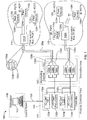
- An example process control system includes a control room (e.g., a control room 108 of FIG. 1 ), a process controller area (e.g. a process controller area 110 of FIG. 1 ), a termination area (e.g., a termination area 140 of FIG. 1 ) and one or more process areas (e.g., process areas 114 and 118 of FIG. 1 ).
- a process area includes a plurality of field devices that perform operations (e.g., controlling valves, controlling motors, controlling boilers, monitoring, measuring parameters, etc.) associated with performing a particular process (e.g., a chemical process, a petroleum process, a pharmaceutical process, a pulp and paper process, etc.).
- the control room typically includes one or more workstations within an environment that is safely accessible by humans.
- the workstations include user applications that users (e.g., engineers, operators, etc.) can access to control operations of the process control system by, for example, changing variable values, process control functions, etc.
- the process controller area includes one or more controllers communicatively coupled to the workstation(s) in the control room. The controllers automate control of the field devices in the process area by executing process control strategies implemented via the workstation.
- An example process strategy involves measuring a pressure using a pressure sensor field device and automatically sending a command to a valve positioner to open or close a flow valve based on the pressure measurement.
- the termination area includes a marshalling cabinet that enables the controllers to communicate with the field devices in the process area.
- the marshalling cabinet includes a plurality of termination or communication modules used to marshal, organize or route signals between termination or communication modules coupled to the field devices and one or more I/O cards communicatively coupled to the controllers.
- the communication modules translate information received from the field devices to a format compatible with the I/O cards and the controllers and translate information from the I/O cards and the controllers to a format compatible with the field devices.
- CMOS complementary metal-oxide-semiconductor
- controller e.g., a process controller, a programmable logic controller, etc.
- An I/O card enables communicatively coupling a controller to a plurality of field devices associated with different data types and/or signal types (e.g., analog input (AI) data types, analog output (AO) data types, discrete input (DI) data types, discrete output (DO) data types, digital input data types, and digital output data types)) and/or different field device communication protocols by translating or converting information communicated between the controller and the field devices.
- an I/O card may be provided with one or more field device interfaces configured to exchange information with a field device using the field device communication protocol associated with that field device.
- Different field device interfaces communicate via different channel types (e.g., analog input (AI) channel types, analog output (AO) channel types, discrete input (DI) channel types, discrete output (DO) channel types, digital input channel types, and digital output channel types)).
- the I/O card can convert information (e.g., voltage levels, digital values, etc.) received from the field device into process information (e.g., pressure measurement values) that the controller can use to perform operations associated with controlling the field device.
- each field device is typically coupled via one or more wires to one or more electrical terminations (e.g., screw terminals) on an I/O card.
- the I/O card electrical terminations, to which each field device is coupled are selected to enable the I/O card to communicate with the field device using the communication signals and communication protocol used by the field device.
- the wires coupling the field devices to the I/O cards must be landed on or wired to I/O card terminals associated with I/O card channels that use the same types of communication signals and protocols as the field devices.
- the wire ends at the field device must typically be un-terminated and re-landed on a replacement field device that uses the desired, different communication signal(s) and/or protocol.
- the wire ends at the I/O card must typically be un-terminated and re-landed on I/O card terminations coupled to a channel that communicates using the desired, different communication signal(s) and/or protocol. Such re-termination or re-landing of field wiring between I/O cards and field devices is time consuming, expensive and error-prone.
- the example apparatus and methods described herein may be used to more flexibly communicatively couple field devices to an I/O card.
- the example apparatus and methods described herein use a pair of communication modules, one of which is removably couplable to a field device and the other which is removably couplable to an I/O card.
- the pair of communication modules provides substantially all of communication software and communications electronic needed to enable the field device to communicate with the I/O card and controller.
- the example communication modules described herein enable a field device to be coupled to an I/O card using any channel of the I/O card, regardless of the communication signal type and/or protocol used by the channel.
- the communication signal(s) and/or protocol used by a field device can be changed by removing and replacing the pair of communication modules with a pair of communication modules that use the desired, different communication signal(s) and/or protocol without having to re-terminate or re-land any wires coupling the field device to a controller I/O card.
- the communication modules of the field device and the I/O card can be removed and replaced with communication modules having the revised communications software and/or electronics without having to remove and re-land any wires coupling the field device to a controller I/O card.
- the communication signal(s) and/or protocol of a field device is to be changed, including updated or upgraded, the field device(s) do not have to be replaced.
- the example communication modules described herein may be self-contained, encapsulated electronic modules that include communications software. Further, these example communication modules which can be removably inserted or otherwise coupled to field devices of varying types, makes (e.g., provided by different manufacturers) and models or I/O cards (e.g., via marshalling cabinets as described in connection with FIG. 1 ).
- the example communication modules may be standardized and used in connection with different types of field devices to provide the communication signal(s) and/or protocol for the field devices. More specifically, the mechanical configuration and interface, including the packaging, electrical connections (e.g., pinout), etc. of the field devices and the I/O card, and the communication modules may be made standard so that any of a number of available communication modules providing different communication protocols, signaling, etc.
- the communication modules can be used with any of a variety of field devices, which may be made by any number of manufacturers.
- the manner in which the communication modules communicate with other electronics in the field devices may also be standardized.
- the communication schemes used to enable communications between the field devices and the communication modules may also be standardized across types, makes, models, etc. of field devices to further facilitate interchangeability of communication modules with field devices.
- the example communication modules described herein can enable field device communications to be standardized, thereby enabling the communication modules to be manufactured without particularity to any one communication signaling or protocol. Instead, such communication signaling or protocols can be assigned or configured by installing an appropriate communication module in a field device post-manufacture of the field device (e.g., when the field device is installed in a process control system or during commissioning). This reduces the number of spare components (e.g., spare field devices) needed and facilitates easy conversion of field devices from one communication protocol or protocol version to another.
- the example methods and apparatus described herein also simplify the manufacture of field devices and I/O cards because the field devices and the I/O cards may no longer have to include substantial amounts of internal communications protocol electronics or software. Thus, the example methods and apparatus described herein eliminate the need for manufacturers to produce as many similar field devices employing different communications signaling or protocols. In addition, manufacturers do not have to produce I/O cards that including a certain number or configuration of channels using different communications signaling or protocols.
- system maintenance costs may be reduced because communications software revisions or upgrades may be easily added by replacing a communication module with another communication module having the revised or upgraded software including software that incorporates new or different features.
- the example communication module described herein can be easily exchanged or replaced without having to access the internal electronics of a field device or I/O card, upgrades and/or alterations of a communication protocol can be performed in situ (i.e., without having to remove and re-terminate or re-land wires at the field device).
- diagnostics of a field device may be included in a communication module and, thus, customers desiring newer or better diagnostic software can exchange a communication module for another communication module containing the desired diagnostics without having to change the communication protocol and/or internal electronics of the field device.
- some example communication modules may include local tagging information such as, for example, field device serial number(s) and/or other field device information.
- local tagging information such as, for example, field device serial number(s) and/or other field device information.
- the inclusion of any or all of the communications signaling or protocols, software, diagnostic information and/or local tagging information in the example communication modules facilitates configuration of field devices and evaluation field device operating conditions, history, maintenance needs, etc.
- the communication modules may be coded, e.g., color coded, in accordance with the type of communication signal(s) and/or protocol, upgrades, updates, diagnostics, etc. included therein.
- the coding scheme facilitates identification of the proper communication modules for coupling to the field device(s) and/or I/O card(s).
- the example apparatus and methods described herein involve using an example universal internal I/O bus (e.g., a common or shared analog or digital communication bus) that communicatively couples one or more first communication modules to one or more I/O cards communicatively coupled to a controller.
- Each first communication module is coupled to a respective second communication module using a respective external bus (e.g., an analog or a digital bus).
- the second communication modules are communicatively coupled to one or more respective field devices using a respective internal field device bus (e.g., an analog bus or a digital bus internal to each field device), which may be standardized across different types, makes, models, etc. of field devices.
- communication module(s) may refer to the communication module(s) associated with an I/O card, to communication module(s) associated with a field device and/or to any type of communication module(s) regardless of location.
- the designations of "first,” “second,” “other,” “another,” “complimentary,” etc. are not meant to restrictively reference a specific communication module in a specific location in the examples described herein. Rather, these terms are used to differentiate different communication modules in the described examples.
- the communication modules removably coupled to field devices are configured to receive field device information from the field devices via the internal field device buses and communicate the field device information to other communication modules, which are associated with one or more I/O cards, via the external bus. These other communication modules communicate the field device information to the controller I/O cards via their internal I/O busses by, for example, packetizing the field device information and communicating the packetized information to the I/O cards.
- the field device information may include, for example, field device identification information (e.g., device tags, electronic serial numbers, etc.), field device status information (e.g., communication status, diagnostic health information (open loop, short, etc.)), field device activity information (e.g., process variable (PV) values), field device description information (e.g., field device type or function such as, for example, valve actuator, temperature sensor, pressure sensor, flow sensor, etc.), field device connection configuration information (e.g., multi-drop bus connection, point-to-point connection, etc.), field device bus or segment identification information (e.g., field device bus or field device segment via which a field device is communicatively coupled to communication module), field device data type information (e.g., a data type descriptor indicative of the data type used by a particular field device) and/or other diagnostic information.
- the I/O card(s) can extract the field device information received via the internal I/O bus and communicate the field device information to a controller, which can then communicate some or all of
- I/O cards can packetize the field device information and communicate the packetized field device information to a plurality of communication modules over the internal I/O bus. Each of the communication modules can then extract or depacketize field device information from the packetized communications received from an I/O card and communicate the field device information to a corresponding communication module removably coupled to a field device.
- field device information e.g., commands, instructions, queries, threshold activity values (e.g., threshold PV values), etc.
- I/O cards can packetize the field device information and communicate the packetized field device information to a plurality of communication modules over the internal I/O bus. Each of the communication modules can then extract or depacketize field device information from the packetized communications received from an I/O card and communicate the field device information to a corresponding communication module removably coupled to a field device.
- an example process control system 100 includes a workstation 102 communicatively coupled to a controller 104 via a bus or local area network (LAN) 106, which is commonly referred to as an application control network (ACN).
- the LAN 106 may be implemented using any desired communication medium and protocol.
- the LAN 106 may be based on a hardwired or wireless Ethernet communication protocol.
- any other suitable wired or wireless communication medium and protocol could be used.
- the workstation 102 may be configured to perform operations associated with one or more information technology applications, user-interactive applications, and/or communication applications.
- the workstation 102 may be configured to perform operations associated with process control-related applications and communication applications that enable the workstation 102 and the controller 104 to communicate with other devices or systems using any desired communication media (e.g., wireless, hardwired, etc.) and protocols (e.g., HTTP, SOAP, etc.).
- the controller 104 may be configured to perform one or more process control routines or functions that have been generated by a system engineer or other system operator using, for example, the workstation 102 or any other workstation and which have been downloaded to and instantiated in the controller 104.
- the workstation 102 is located in the control room 108 and the controller 104 is located in the process controller area 110 separate from the control room 108.
- the example process control system 100 includes field devices 112a-c in the first process area 114 and field devices 116a-c in the second process control area 118.
- the example process control system 100 is provided with field junction boxes (FJB's) 120a-b and a marshalling cabinet 122.
- FJB's field junction boxes
- Each of the field junction boxes 120a-b routes signals from respective ones of the field devices 112a-c and 116a-c to the marshalling cabinet 122.
- the marshalling cabinet 122 in turn, marshals (e.g., organizes, groups, etc) information received from field devices 112a-c and 116a-c and routes the field device information to respective I/O cards (e.g., I/O cards 132a-b and 134a-b) of the controller 104.
- the communications between the controller 104 and the field devices 112a-c and 116a-c are bidirectional so that the marshalling cabinet 122 is also used to route information received from I/O cards of the controller 104 to respective ones of the field devices 112a-c and 116a-c via the field junction boxes 120a-b.
- first communication modules 124a-c and 126a-c are included in the marshalling cabinet 122, and second communication modules 124d-f and 126d-f are coupled to the field devices 112a-c and 116a-c, respectively.
- the field devices 112a-c are communicatively coupled to the second communication modules 124d-f and to the field junction box 120a via electrically conductive, wireless, and/or optical communication media
- the field devices 116a-c are communicatively coupled to the second communication modules 126d-f and to the field junction box 120b via electrically conductive (e.g., hardwired), wireless, and/or optical communication media.
- the field junction boxes 120a-b may be provided with one or more wired, wireless, and/or optical data transceivers to communicate with wired, wireless, and/or optical transceivers of the second communication modules 124d-f and 126d-f.
- the field junction box 120b is communicatively coupled wirelessly to the second communication module 126f and the field device 116c.
- the marshalling cabinet 122 may be omitted and signals from the second communication modules 124d-f and 126d-f of the field devices 112a-c and 116a-c can be routed from the field junction boxes 120a-b directly to the first communication modules 124a-c and 126a-c, which may be removably coupled to the I/O cards 132a-b and 134a-b of the controller 104 without intervening structure (i.e., without the marshalling cabinet 122).
- the field junction boxes 120a-b may be omitted and the second communication modules 124d-f and 126d-f of the field devices 112a-c and 116a-c can be directly coupled to the first communication modules 124a-c and 126a-c of the marshalling cabinet 122.
- the field devices 112a-c and 116a-c may be Fieldbus compliant valves, actuators, sensors, etc., in which case the field devices 112a-c and 116a-c communicate via a digital data bus using the well-known FOUNDATION Fieldbus communication protocol.
- the field devices 112a-c and 116a-c could instead be Profibus, HART, or AS-i compliant devices that communicate via the data bus using the well-known Profibus and HART communication protocols.
- the field devices 112a-c and 116a-c can communicate information using analog communications or discrete communications instead of digital communications.
- the communication protocols can be used to communicate information associated with different data types.
- Each of the field devices 112a-c and 116a-c is configured to store field device identification information.
- the field device identification information may be a physical device tag (PDT) value, a device tag name, an electronic serial number, etc. that uniquely identifies each of the field devices 112a-c and 116a-c.
- PDT physical device tag
- the field devices 112a-c store field device identification information in the form of physical device tag values PDTO-PDT2 and the field devices 116a-c store field device identification information in the form of physical device tag values PDT3-PDT5.
- the field device identification information may be stored or programmed in the field devices 112a-c and 116a-c by a field device manufacturer and/or by an operator or engineer involved in installation and/or commissioning of the field devices 112a-c and 116a-c.
- the system 100 To route information associated with (e.g., collected by) the field devices 112a-c and 116a-c to the process controller area 110, the system 100 includes the plurality of communication modules 124a-f and 126a-f, as noted above.
- the communication modules 124a-f are configured to marshal information associated with the field devices 112a-c in the first process area 114
- the communication modules 126a-f are configured to marshal information associated with the field devices 116a-c in the second process area 118.
- the communication modules 124a-c and 126a-c are communicatively coupled to the field junction boxes 120a-b via respective multi-conductor cables 128a and 128b (e.g., a multi-bus cable).
- the communication modules 124a-c and 126a-c can be installed in respective ones of the field junction boxes 120a-b.
- FIG. 1 depicts a point-to-point configuration in which each conductor or conductor pair (e.g., bus, twisted pair communication medium, two-wire communication medium, etc.) in the multi-conductor cables 128a-b communicates information uniquely associated with a respective one of the field devices 112a-c and 116a-c via the associated communication modules 124d-f and 126d-f.
- the multi-conductor cable 128a includes a first conductor 130a, a second conductor 130b, and a third conductor 130c.
- the first conductor 130a is used to form a first data bus configured to communicate information between the first communication module 124a and the second communication module 124d associated with the field device 112a
- the second conductor 130b is used to form a second data bus configured to communicate information between the first communication module 124b and the second communication module 124e associated with the field device 112b
- the third conductor 130c is used to form a third data bus configured to communicate information between the first communication module 124c and the second communication module 124e associated with the field device 112c.
- each of the first communication modules 124a-c and 126a-c can be communicatively coupled with one or more second communication modules associated with other field devices.
- the communication module 124a can be communicatively coupled via the first conductor 130a to the second communication module 124d associated with the field device 112a and to another communication module associated with another field device (not shown).
- a communication module can be configured to communicate wirelessly with a plurality of field devices using a wireless mesh network.
- the second communication modules 124d-f and 126d-f are communicatively coupled directly to the field devices 112a-c and 116a-c as, for example, a removably pluggable or insertable device having a charm-like form (e.g., a circuit card having a protective cover or housing and a pluggable electrical connector).
- the second communication modules 124d-f and 126d-f may be communicatively coupled to the field devices 112a-c and 116a-c via intermediate structure(s) or device(s).
- the first communication modules 124a-c and 126a-c are communicatively coupled directly to the marshalling cabinet 122 (alternatively, to the I/O cards 132a-b and 134a-b) as, for example, a removably pluggable or insertable device having a charm-like form (e.g., a circuit card having a protective cover or housing and a pluggable electrical connector).
- the first communication modules 124a-c and 126a-c may be communicatively coupled to the marshalling cabinet 122 and/or I/O cards 132a-b, 134a-b via intermediate structure(s) or device(s).
- Each of the communication module pairs may be configured to communicate using a different communication protocol and/or data type.
- the first communication module 124a may include an external bus interface to communicate with the second communication module 124d of the field device 112a using digital data while the first communication module 124b may include an analog external bus interface to communicate with the second communication module 124e of the field device 112b using analog data.
- the controller 104 is provided with the plurality of I/O cards 132a-b and 134a-b.
- the I/O cards 132a-b are configured to control I/O communications between the controller 104 (and/or the workstation 102) and the field devices 112a-c in the first process area 114
- the I/O cards 134a-b are configured to control I/O communications between the controller 104 (and/or the workstation 102) and the field devices 116a-c in the second process area 118.
- the I/O cards 132a-b and 134a-b reside in the controller 104.
- the I/O cards, 132a-b and 134a-b communicate the information to the controller 104 which, in turn, communicates the information to the workstation 102.
- the workstation 102 communicates the information to the controller 104, the controller 104 communicates the information to the I/O cards 132a-b and 134a-b, and the I/O cards 132a-b and 134a-b communicate the information to the field devices 112a-c and 116a-c via the first communication modules 124a-c and 126a-c and the second communication modules 124d-f and 126d-f.
- the I/O cards 132a-b and 134a-b can be communicatively coupled to the LAN 106 internal to the controller 104 so that the I/O cards 132a-b and 134a-b can communicate directly with the workstation 102 and/or the controller 104.
- the I/O cards 132b and 134b are configured as redundant I/O cards. That is, if the I/O card 132a fails, the redundant I/O card 132b assumes control and performs the same operations as the I/O card 132a would otherwise perform. Similarly, the redundant I/O card 134b assumes control if the I/O card 134a fails.
- the illustrated example of FIG. 1 enables routing data associated with different field device data types (e.g., the data types or channel types used by the field devices 112a-c and 116a-c) to the I/O cards 132a-b and 134a-b without having to implement a plurality of different field device interface types for different communication signaling and/or protocols on the I/O cards 132a-b and 134a-b.
- different field device data types e.g., the data types or channel types used by the field devices 112a-c and 116a-c
- an I/O card having one interface type can communicate with a plurality of field devices using different field device communication signaling and/or protocols, as defined by the first or I/O communication modules 124a-b and 126a-b.
- the marshalling cabinet 122, the communication modules 124a-f and 126a-f, the I/O cards 132a-b and 134a-b, and the controller 104 facilitate migrating existing process control system installations to a configuration substantially similar to the configuration of the example process control system 100 of FIG. 1 .
- the communication modules 124a-f and 126a-f can be configured to include any suitable interface type
- the communication modules 124a-f and 126a-f can be configured to be communicatively coupled to any type of field device.
- the controller 104 can be configured to include a known LAN interface to communicate via a LAN to an already installed workstation.
- the I/O cards 132a-b and 134a-b can be installed in or communicatively coupled to known controllers so that controllers already installed in a process control system need not be replaced.
- a single communication module may communicatively couple a field device, which has standardized protocols, with an I/O card.
- the communication module may use the communication signaling and protocol of the I/O channel to which the communication module is attached.
- the communication protocol of a field device may be changed by replacing the communication module with a communication module that uses a different communication protocol and re-landing a bus coupled to the communication module to a different channel on the I/O card that uses the desired communication protocol.
- This example enables field devices to communicate using different protocols without requiring a replacement of the field device itself.
- the communication modules can be configured to be removably, communicatively coupled to existing field devices already installed in a process control system.
- a single communication module may be communicatively coupled between an I/O card and a field device having multiple communication ports.
- the multiple ports may include, for example, a standardized port, a HART port, a FOUNDATION Fieldbus port, etc.
- the communication protocol of a field device can be changed by replacing the communication module with a communication module that uses a different communication protocol and coupling the replacement communication module to the corresponding port on the field device.
- This example enables field devices to communicate using different protocols without requiring a replacement of the field device itself.
- the communication modules can be configured to be communicatively coupled to existing field devices already installed in a process control system.
- the I/O card 132a includes a data structure 133 and the I/O card 134a includes a data structure 135.
- the data structure 133 stores the field device identification numbers (e.g., field device identification information) or other information corresponding to field devices (e.g., the field devices 112a-c) that are coupled to the I/O card 132a via the internal I/O bus 136a and the data structure 135 stored information corresponding to the field devices 116a-c.
- the field device identification numbers or other information stored in the data structure 133 may be used for identification or other purposes or other types of information corresponding to field devices that is transmitted to the workstation (e.g., the workstation 102).
- the data structures 133 and 135 can be populated by engineers, operators, and/or users via the workstation 102 during a configuration, commissioning or operation of the example process control system 100.
- the data structures 133 and 135 may also be populated automatically after a field device is coupled to the internal I/O buses 136a-b.
- the redundant I/O card 132b stores a data structure identical to the data structure 133
- the redundant I/O card 134b stores a data structure identical to the data structure 135.
- the data structures 133 and 135 can be stored in the workstation 102.
- FIG. 2 shows an example implementation of a communication module 200, which may represent any of the example communication modules described herein.
- the example communication module 200 of FIG. 2 includes an external bus interface 202 to enable the communication module 200 to communicate with, for example, a complimentary or corresponding communication module.
- the communication modules 124a and 124d use respective the external bus interfaces 202 to communicate with each other.
- the communication module 200 is provided with an address identifier 204.
- the address identifier 204 may be configured to query an I/O card or a field device for a communication module address (e.g., a network address) when the communication module 200 is plugged into an I/O card or a field device. In this manner, the communication module 200 can use the communication module address as a source and/or destination address when communicating information between the I/O card and the field device.
- the communication module 200 is provided with an operation controller 206.
- the operation controller 206 can be implemented using a microprocessor or a microcontroller.
- the operation controller 206 communicates instructions or commands to other portions of the communication module 200 to control the operations of those portions.
- the example communication module 200 is also provided with an external bus communication processor 208 to exchange information with other communication modules, via an external bus (e.g., the external busses 130a-c of FIG. 1 ).
- the external bus communication processor 208 packetizes information for transmission to another communication module and depacketizes information received from the other communication module.
- the packetized information is communicated to the external bus interface 202 for transmission over an external bus.
- the external bus communication processor 208 generates header information for each packet to be transmitted and reads header information from received packets.
- Example header information includes a destination address (e.g., a network address of an I/O card), a source address (e.g., the network address of the communication module 200), a packet type or data type (e.g., analog field device information, field device information, command information, temperature information, real-time data values, etc.), and error checking information (e.g., cyclical-redundancy-check (CRC) information).
- a destination address e.g., a network address of an I/O card
- a source address e.g., the network address of the communication module 200
- a packet type or data type e.g., analog field device information, field device information, command information, temperature information, real-time data values, etc.
- error checking information e.g., cyclical-redundancy-check (CRC) information
- CRC cyclical-redundancy-check
- the communication module 200 is provided with a field power controller 210.
- the power supply e.g., a power supply 514 of FIG. 5
- the field power controller 210 is configured to condition, regulate, and step up and/or step down the electrical power provided to the communication module 200 by an external power supply.
- the field power controller 210 is configured to limit the amount of electrical power used to communicate with field devices and/or delivered to the field devices to substantially reduce or eliminate the risk of sparking in flammable or combustible environments.
- the communication module 200 is provided with a power converter 212.
- the circuitry used to implement the communication module 200 uses one or more voltage levels (e.g., 3.3 V) that are different from the voltage levels required by the field device to which the communication module 200 is coupled.
- the power converter 212 is configured to provide the different voltage levels for the communication module 200 to communicate with the field device using the power received from the power supply.
- the electrical power outputs generated by the power converter 212 are used to power the communication module 200 and the field device coupled thereto and to communicate information between the communication module 200 and the field device via another communication module.
- Some field device communication protocols require relatively higher or lower voltage levels and/or electrical current levels than other communication protocols.
- the field power controller 210 controls the power converter 212 to provide the voltage level(s) to power the field device and to communicate with the field device.
- the communication module 200 is provided with one or more isolation device(s) 214.
- the isolation device(s) 214 may be implemented using galvanic isolators and/or optical isolators. An example isolation configuration is described in detail below in connection with FIG. 5 .
- the communication module 200 is provided with a digital-to-analog converter 216 and an analog-to-digital converter 218.
- the digital-to-analog converter 216 is configured to convert digitally represented values (e.g., measurement values) or information received from a field device, an I/O card and/or another communication module to analog values or information for further communication in a system (e.g., the process control system 100 of FIG. 1 ).
- the analog-to-digital converter 218 is configured to convert analog values (e.g., measurement values) or information received from a field device, an I/O card and/or another communication module to digitally represented values or information for further communication in a system (e.g., the process control system 100 of FIG. 1 ).
- the digital-to-analog converter 216 and/or the analog-to-digital converter 218 may be omitted from the communication module 200.
- the communication module 200 is provided with an internal bus communication processor 220.
- the internal bus communication processor 220 ensures that information received from another communication module and, thus, from a field device and/or an I/O card, is in the correct format and voltage type (e.g., analog or digital) to be communicated to the I/O card and/or the field device to which the communication module 200 is coupled.
- the internal bus communication processor 220 is also configured to packetize or depacketize information if the I/O card and/or the field device to which the communication module 200 is coupled if configured to communicate using digital information.
- the internal bus communication processor 220 is configured to extract information received from an I/O card and/or a field device and communicate that information to the analog-to-digital converter 218 and/or to the external bus communication processor 208 for subsequent communication to another communication module and, thus, a field device and/or an I/O card.
- the example communication module 200 is also provided with an internal interface 222 ( FIGS. 2 and 3 ) configured to communicatively couple the communication module 200 to I/O cards (e.g., the I/O cards132a-b of FIG. 1 or with any other I/O cards) and/or to a field device (e.g., the field device 112a of FIG. 1 or with any other field devices).
- I/O cards e.g., the I/O cards132a-b of FIG. 1 or with any other I/O cards
- a field device e.g., the field device 112a of FIG. 1 or with any other field devices.
- the information packetized by the internal bus communication processor 220 is communicated to the internal interface 222 for transmission over an internal bus (e.g., the internal busses 136a-b of FIG. 1 ) to an I/O card and/or to a field device to which the communication module 200 is coupled.
- an internal bus e.g., the internal busses 136a-b of
- the internal bus communication processor 220 is also configured to timestamp information received from an I/O card, a field device or the other communication module. Generating timestamps at the communication module 200 facilitates implementing sequence of events (SOE) operations using timestamp accuracies in the sub-millisecond range. For example, the timestamps and respective information can be communicated to the controller 104 and/or the workstation 102. Sequence of events operations performed by, for example, the workstation 102 ( FIG. 1 ) (or any other processor system) can then be used to analyze what happened before, during, and/or after a particular state of operation (e.g., a failure mode) to determine what caused the particular state of operation to occur. Timestamping in the sub-millisecond range also enables capturing events using relatively higher granularity. In some example implementations, the internal bus communication processor 220 and the operation controller 206 can be implemented using the same microprocessor or microcontroller.
- internal communication processors similar to the internal bus communication processor 220 are provided with communication protocol functions or other communication functions (e.g., Fieldbus communication protocol functions, HART communication protocol functions, etc.) corresponding to the type of field device and/or I/O channel with which they are configured to communicate. For example, if the I/O channel associated with internal I/O bus 136a is configured to use the HART communication protocol, the internal communication controller 220 of the communication module 124a is provided with HART communication protocol functions.
- communication protocol functions or other communication functions e.g., Fieldbus communication protocol functions, HART communication protocol functions, etc.
- the internal communication processor 220 formats the information in accordance with the HART communication protocol and delivers the information to the second communication module 124d and the field device 112a. If the second communication module 124d does not communicate using the HART communication protocol, the second communication module 124d may be removed and replaced with another communication module that is configured to implement the HART protocol. Thus, the field device 112a can be modified to communicate using a different protocol to match that of the I/O bus 136a, thereby eliminating the need to re-land or re-terminate the internal I/O bus 136a at the I/O card 132a.
- the internal bus communication processor 220 is configured to process pass-through messages.
- Pass-through messages originate at a workstation (e.g., the workstation 102 of FIG. 1 ) and are communicated as payload (e.g., the data portion of a communication packet) through a controller (e.g., the controller 104 of FIG. 1 ) to a communication module (e.g., the communication module 124a of FIG. 1 ) for delivery to a field device (e.g., the field device 112a, via the second communication module 124d).
- a workstation e.g., the workstation 102 of FIG. 1
- payload e.g., the data portion of a communication packet
- a controller e.g., the controller 104 of FIG. 1
- a communication module e.g., the communication module 124a of FIG. 1
- a field device e.g., the field device 112a, via the second communication module 124d.
- a message originating at the workstation 102 and intended to be delivered to the field device 112a is tagged at the workstation 102 with a communication protocol descriptor (e.g., a HART protocol descriptor) and/or is formatted in accordance with a communication protocol of the field device 112a.
- the workstation 102 then wraps the message into a payload(s) of one or more communication packets to deliver the message from the workstation 102, through the I/O controller 104 to the communication module 124a as a pass-through message. Wrapping the message involves, for example, packetizing the message with header information in accordance with a communication protocol (e.g., a Fieldbus protocol, a HART protocol, etc.) used to communicate with the field devices.
- a communication protocol e.g., a Fieldbus protocol, a HART protocol, etc.
- the internal bus communication processor 220 extracts the payload(s) from the received communication packet(s).
- the external bus communication controller 208 ( FIG. 2 ) then unwraps the pass-through message from the payload(s), formats the message in accordance with the communication protocol descriptor generated by the workstation 102 (if not already formatted at the workstation 102), and communicates the message to the field device 112a, via the second communication module 124d.
- the message may be passed without modification from the first communication module 124a to the second communication module 124d. Then the second communication module 124d unwraps the pass-through message from the payload(s), formats the message in accordance with the communication protocol descriptor generated by the workstation 102 (if not already formatted at the workstation 102), and communicates the message to the field device 112a.
- the internal communication processor 220 is also configured to communicate pass-through messages to the workstation 102 in a similar manner. For example, if the field device 112a generates a message (e.g., a response to the workstation message or any other message) intended to be delivered to the workstation 102, the internal bus communication processor 220 wraps the message from the field device 112a into the payload of one or more communication packets and the external bus communication processor 208 communicates the one or more packets containing the wrapped message to the first communication module 124a and to the I/O card 132a. When the workstation 102 receives the packets from the controller 104 containing the wrapped message, the workstation 102 can unwrap and process the message.
- a message e.g., a response to the workstation message or any other message
- the internal bus communication processor 220 wraps the message from the field device 112a into the payload of one or more communication packets and the external bus communication processor 208 communicates the one or more packets containing the wrapped message to
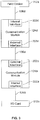
- FIG. 3 is a block diagram illustrating an example electrical connection of two example communication modules, an example field device and an example I/O card.
- the communication modules 124a,d are illustrated.
- any other communication modules may be coupled to any other communication module, I/O card and/or field device in the same or a similar manner.
- the I/O card 132a and the field device 112a are illustrated in this example, but any other I/O card and/or field device may be may be coupled to any other communication module in the same or a similar manner.
- the I/O card 132a is communicatively coupled to a first internal interface 222a of the first communication module 124a via the internal I/O bus 136a.
- a conductor or bus 130a couples the first communication module 124a to a second external interface 202d of the second communication module 124d.
- the second communication module 124d is coupled, via a second internal interface 222d and an internal field device bus 136d, to the field device 112a.
- FIG. 4 shows an example mechanical connection of the example communication module 200 and an example field device 400, which may represent any of the example communication modules and/or field devices described herein.
- the example communication module 200 includes one or more contacts 404 (e.g., pins, tabs, traces, etc.) that communicatively couple and/or electrically couple the communication module 200 to the field device 400.
- the communication module 200 is coupled to the field device 400 via an intervening base 402.
- the base 402 is provided with fasteners 406 (e.g., screws), which may be, for example, a field device interface, to tie down, terminate or secure conductive communication media (e.g., wire ends) from an I/O bus.
- fasteners 406 e.g., screws
- the fasteners 406 are communicatively coupled to one or more of the contacts 404 to enable conveying of signals and communicating information between the communication module 200, the field device 400 and an I/O card.
- the base 402 may be provided with any other suitable type of field device interface (e.g., a socket) instead of fasteners 406.
- the base 402 is provided with a field device contact or connector 408.
- the field device connector 408 engages an internal bus of the field device 400.
- the field device connector 408 may be implemented using any suitable interface including a relatively simple interface such as, for example, a punch block.
- the field device connector 408 is connected to one or more of the contacts 404 of the communication module 200.
- the communication module 200 also includes a cover 410, which may be used to shield the communication module 200 and/or the connection of the communication module 200 and the field device 400 from the surrounding environment.
- the cover 410 prevents moisture and/or other adverse or otherwise potentially damaging environmental conditions from having a harmful effect on the communication module 200 in process areas that may experience those conditions.
- the cover 410 may be made of any suitable plastic, metal or other material suitable to seal or otherwise protect the communication module 400.
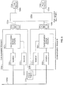
- FIG. 5 depicts an isolation circuit configuration that may be implemented in connection with the example communication modules 124a-b of FIG. 1 to electrically isolate the communication modules 124a-b from one another and the field devices 112a-b from the internal I/O bus 136a.
- communication modules 124a-b are illustrated, however, any other communication module may be coupled to any other communication module, I/O card and/or field device in the same or a similar manner.
- each of the communication modules 124a-b includes respective communication module circuitry 502 and 504 (e.g., one or more of the blocks described above in connection with FIG. 2 ).
- the communication modules 124a-b are connected to their respective field devices 112a-b via the field junction box 120a and complimentary communication modules 124d-e. Also, the communication modules 124a-b are connected to the internal I/O bus 136a and a power supply 514.
- the communication module 124a is provided with an isolation circuit 506.
- the communication module circuitry 502 can be configured to follow (e.g., float) the voltage level of the field device 112a if power surges or other power variations occur in the field device 112a without affecting the voltage of the internal I/O bus 136a and without causing damage to the I/O card 132a ( FIG. 1 ).
- the communication module 124b also includes an isolation circuit 508 configured to isolate the communication module circuitry 504 from the internal I/O bus 136a.
- the isolation circuits 506 and 508 and any other isolation circuits implemented in the communication modules 124a-b may be implemented using optical isolation circuits or galvanic isolation circuits.
- the communication module 124a is provided with an isolation circuit 510.
- the communication module 124b is provided with an isolation circuit 512 to isolate the communication module circuitry 504 from the power supply 514.
- any power variation e.g., power surges, current spikes, etc.
- any power variations in one of the communication modules 124a-b will not damage or adversely affect the operation of the other one of the communication modules 124a-b.
- isolation circuits are provided in known marshalling cabinets, thereby reducing the amount of space available for known communication modules.
- providing the isolation circuits 506, 510, 508, and 512 in the communication modules 124a-b as shown in the illustrated example of FIG. 5 reduces the amount of space required in the marshalling cabinet 122 ( FIG. 1 ) for isolation circuits, thereby increasing the amount of space available for communication modules (e.g., the communication modules 124a-c and 126a-c).
- isolation circuits e.g., the isolation circuits 506, 508, 510, and 512
- communication modules e.g., the communication modules 124a-b
- isolation circuits e.g., the isolation circuits 506, 508, 510, and 512
- communication modules e.g., the communication modules 124a-b
- isolation circuits e.g., the isolation circuits 506, 508, 510, and 512
- communication modules e.g., the communication modules 124a-b
- some of the communication modules 124a-f and 126a-f of FIG. 1 may be implemented without isolation circuits.
- An additional isolation circuit(s) may be coupled between the communication module circuitry 502 and the field device 112a to isolate the communication module 124a from the other communication module 124d and the field device 112a.
- an additional isolation circuit may be coupled between the communication module circuitry 504 and the field device 112b to isolate the communication module 124b from the other communication module 124e and the field device 112b.
- the communication module circuitry 502 and 504 can be configured to follow (e.g., float relative to) the voltage levels of the field devices 112a and 112b, respectively, if power surges or other power variations occur in the I/O card 132a ( FIG. 1 ), without affecting the voltage of the external busses 130a and 130b, respectively, and without causing damage to the field device 112a and 112b.
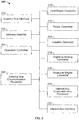
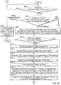
- FIGS. 6A and 6B are flowcharts of example methods that may be used to implement communication modules (e.g., the communication modules 124a-f and 200 of FIGS. 1 and 2 ).
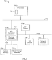
- the example methods of FIGS. 6A and 6B may be implemented using machine readable instructions comprising a program for execution by a processor (e.g., the processor 712 shown in an example processor system 710 of FIG. 7 ).
- the program may be embodied in software stored on a tangible computer or processor readable medium such as a CD-ROM, a floppy disk, a hard drive, a digital versatile disk (DVD), or a memory associated with a processor 712 ( Fig.
- FIGS. 6A and 6B the example methods of FIGS. 6A and 6B are described in connection with the example communication modules 124a, d of FIG. 1 and the example detailed communication module implementation of FIGS. 2 and 3 .
- the example methods of FIGS. 6A and 6B may be used to implement any other communication module(s).
- the flowchart of FIGS. 6A and 6B is used to describe how the example communication modules 124a, d communicate information between the I/O card 132a and the field device 112a.
- the communication module 124a, d determines whether it has received communication information (block 602). For example, the communication module 124a, d determines that it has received communication information if the external bus communication processor 208 ( FIG. 2 ) or the internal bus communication processor 220 indicates via, for example, an interrupt or a status register that communication information has been received. If the communication module 124a, d determines that it has not received communication information (block 602), control remains at block 602 until the communication module 124a, d receives communication information.
- the communication module 124a, d determines whether it received the communication information from a field device (e.g., the field device 112a of FIG. 1 ) (block 604) based on, for example, an interrupt or status register of the internal bus communication processor 220 ( FIG. 2 ) when the communication module 124d is coupled to a field device. If the communication module 124d determines that it has received communication information from the field device 112a (block 604), then the internal bus communication processor 220 extracts the field device information and the field device identification information from the received communication information associated with the field device 112a based on a field device communication protocol (block 606).
- a field device e.g., the field device 112a of FIG. 1
- the internal bus communication processor 220 extracts the field device information and the field device identification information from the received communication information associated with the field device 112a based on a field device communication protocol (block 606).
- the field device information may include, for example, field device identification information (e.g., device tags, electronic serial numbers, etc.), field device status information (e.g., communication status, diagnostic health information (open loop, short, etc.)), field device activity information (e.g., process variable (PV) values), field device description information (e.g., field device type or function such as, for example, valve actuator, temperature sensor, pressure sensor, flow sensor, etc.), field device connection configuration information (e.g., multi-drop bus connection, point-to-point connection, etc.), field device bus or segment identification information (e.g., field device bus or field device segment via which field device is communicatively coupled to communication module), and/or field device data type information (e.g., analog in (AI) data types, analog out (AO) data types, discrete in (DI) data types (e.g., digital in data types), discrete out (DO) data types (e.g., digital out data types), etc.).
- field device identification information e.g.
- the field device communication protocol may be any protocol (e.g., a Fieldbus protocol, a HART protocol, an AS-I protocol, a Profibus protocol, etc.) used by the field device 112a or the communication protocol assigned to the field device 112a by the communication module 126d.
- the field device communication processor 220 only extracts the field device information from the received communication information and the field device identification information identifying the field device 112a is stored in the communication module 124d.
- the field device 112a can communicate its identification information to the communication module 124d and the communication module 124d can store the identification information.
- this information may also be stored in the database 133 or 135, the workstation 102, etc. This information may also be stored in the other communication module 124a.
- the internal bus communication processor 220 determines whether an analog-to-digital conversion is needed (block 608). For example, if the field device 112a communicates analog measurement values, the internal bus communication processor 220 determines that an analog to digital conversion is needed or required (block 608). If an analog to digital conversion is required, the analog-to-digital converter 218 ( FIG. 2 ) performs the conversion on the received information (block 610).
- the internal bus communication processor 220 identifies the data type (e.g., analog, digital, temperature measurement, etc.) associated with the received field device information (block 612) and generates a data type descriptor corresponding to the received field device information (block 614).
- the communication module 124d can store a data type descriptor that indicates the data type that it will always receive from the field device 112a or the field device 112a can communicate a data type to the communication module 124d that the field device communication processor 220 uses to generate the data type descriptor at block 610.
- the field device 112a does not include any internal communication circuitry and/or software but, rather, all communication circuitry and/or software are provided by the communication module, many of the blocks shown in FIGS. 6A and 6B may be skipped. For example, conversion from the communication protocol of the field device to that of the external bus (e.g., I/O channel) may be unnecessary where the communication protocol is initially provided by the communication module 124d.
- the external bus e.g., I/O channel
- the external bus communication processor 208 determines the destination address of the I/O card 132a (block 616) to which the communication module 124d (and ultimately the communication module 124a as detailed below) is to communicate the information received from the field device 112a. For example the external bus communication processor 208 ( FIG. 2 ) can obtain the destination address of the I/O card 132a from the address identifier 204 ( FIG. 2 ). In addition, the external bus communication processor 208 determines or generates error checking data (block 620) to communicate to the I/O card 132a to ensure that the field device information is received by the I/O card 132a without errors. For example, the external bus communication processor 208 can generate cyclical error check (CRC) error checking bits. This may also be completed by the communication module 124a.
- CRC cyclical error check
- the external bus communication processor 208 then packetizes the field device information, the field device identification information, the data type descriptor, the destination address of the I/O card 132a, the source address of the communication module 124d, and the error checking data based on an external bus communication protocol (block 622).
- the external bus communication protocol may be implemented using, for example, a TPC-based protocol, a UDP-based protocol, etc.
- the external bus communication processor 208 can obtain the source address of the communication module 124d from the address identifier 204 ( FIG. 2 ).
- the external bus interface 202 ( FIG. 2 ) then communicates the packetized information via an external bus to the other communication module 124a (block 624).
- One or more of the blocks shown in FIGS. 6A may be completed by one or more other communication modules than the specific example detailed above.
- the communication module 124d may communicate the information to the other communication module 124a.
- the other communication module 124a may then determine the destination address of the I/O card 132a (block 620) and perform any subsequent methods detailed herein.
- the communication module 124a determines that the communication information detected at block 602 is from the I/O card 132a
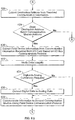
- the internal bus communication processor 220 extracts a destination address from the received communication information (block 626).
- the external bus communication processor 220 determines if the extracted destination address matches a destination address of the second communication module 124d (block 628) obtained from the address interface 204. If the destination address does not match the address of the communication module 124d (e.g., the received information was not intended for delivery to the communication module 124d) (block 628), control returns to block 602 ( FIG. 6A ).
- the internal bus communication processor 220 extracts the field device information from the received communication information based on the internal bus communication protocol (block 630) and verifies the integrity of the data (block 632) using, for example, a CRC verification process based on error detection information in the received communication information.
- the internal bus communication processor 220 determines at block 632 that an error exists in the received communication information, the internal bus communication processor 220 sends a message to the I/O card 132a requesting a re-transmit.
- the internal bus communication processor 220 determines whether a digital-to-analog conversion is required (block 634). For example, if a data type descriptor stored in the communication module 124a indicates that the field device 112a requires analog information, then the internal bus communication processor 220 determines that a digital-to-analog conversion is required (block 634). If a digital-to-analog conversion is required (block 634), the digital-to-analog converter 216 ( FIG. 2 ) performs the digital-to-analog conversion on the field device information (block 636).
- the external communication processor 208 communicates the field device information to the second communication module 124d and, thus, to the field device 112a via the external interface 222 ( FIG. 2 ) using the field device communication protocol of the field device 112a or the communication protocol assigned thereto by the communication module 124d (block 638).
- the process of FIGS. 6A and 6B returns to block 602.
- the other of the first or second communication modules 124a, d will detect a communication from the first one of the communication modules 124a, d that performed the process (block 602). Then the other of the first or second communication modules 124a, d detecting the communication communicates the received information to the device coupled to its internal interface (block 640). That is, the first communication module 124a communicates the information received from the second communication module 124d to the I/O card 132a, and the second communication module 124d communicates information received from the first communication module 124a to the field device 112a.
- the other of the first and/or second communication modules 124a, d may execute one or more of the steps detailed herein.
- the process of FIGS. 6A and B ends and/or control is returned to, for example, a calling process or function.
- FIG. 7 is a block diagram of the example processor system 710 that may be used to implement the apparatus and methods described herein.
- processor systems similar or identical to the example processor system 710 may be used to implement the workstation 102, the controller 104, the I/O cards 132a-b and 134a-b, and/or the communication modules 124a-c and 126a-c of FIG. 1 .
- the example processor system 710 is described below as including a plurality of peripherals, interfaces, chips, memories, etc., one or more of those elements may be omitted from other example processor systems used to implement one or more of the workstation 102, the controller 104, the I/O card 132a, and/or the communication modules 124a-c and 126a-c.
- the processor system 710 includes the processor 712 that is coupled to an interconnection bus 714.
- the processor 712 includes a register set or register space 716, which is depicted in FIG. 7 as being entirely on-chip, but which could alternatively be located entirely or partially off-chip and directly coupled to the processor 712 via dedicated electrical connections and/or via the interconnection bus 714.
- the processor 712 may be any suitable processor, processing unit or microprocessor.
- the system 710 may be a multi-processor system and, thus, may include one or more additional processors that are identical or similar to the processor 712 and that are communicatively coupled to the interconnection bus 714.
- the processor 712 of FIG. 7 is coupled to a chipset 718, which includes a memory controller 720 and a peripheral input/output (I/O) controller 722.
- a chipset typically provides I/O and memory management functions as well as a plurality of general purpose and/or special purpose registers, timers, etc. that are accessible or used by one or more processors coupled to the chipset 718.
- the memory controller 720 performs functions that enable the processor 712 (or processors if there are multiple processors) to access a system memory 724 and a mass storage memory 725.
- the system memory 724 may include any desired type of volatile and/or non-volatile memory such as, for example, static random access memory (SRAM), dynamic random access memory (DRAM), flash memory, read-only memory (ROM), etc.
- the mass storage memory 725 may include any desired type of mass storage device. For example, if the example processor system 710 is used to implement the workstation 102 ( FIG. 1 ), the mass storage memory 725 may include a hard disk drive, an optical drive, a tape storage device, etc.
- the mass storage memory 725 may include a solid-state memory (e.g., a flash memory, a RAM memory, etc.), a magnetic memory (e.g., a hard drive), or any other memory suitable for mass storage in the controller 104, the I/O cards 132a-b and 134a-b, or the communication modules 124a-f and 126a-f.
- a solid-state memory e.g., a flash memory, a RAM memory, etc.
- a magnetic memory e.g., a hard drive
- the peripheral I/O controller 722 performs functions that enable the processor 712 to communicate with peripheral input/output (I/O) devices 726 and 728 and a network interface 730 via a peripheral I/O bus 732.
- the I/O devices 726 and 728 may be any desired type of I/O device such as, for example, a keyboard, a display (e.g., a liquid crystal display (LCD), a cathode ray tube (CRT) display, etc.), a navigation device (e.g., a mouse, a trackball, a capacitive touch pad, a joystick, etc.), etc.
- the network interface 730 may be, for example, an Ethernet device, an asynchronous transfer mode (ATM) device, an 802.11 device, a DSL modem, a cable modem, a cellular modem, etc. that enables the processor system 710 to communicate with another processor system.
- ATM asynchronous transfer mode
- 802.11 a DSL modem
- cable modem a cable modem
- cellular modem a cellular modem
- memory controller 720 and the I/O controller 722 are depicted in FIG. 7 as separate functional blocks within the chipset 718, the functions performed by these blocks may be integrated within a single semiconductor circuit or may be implemented using two or more separate integrated circuits.
- the example methods and systems described herein advantageously enable an operator of a process control system to employ a plurality of communication modules for a plurality of communication protocols that are interchangeably couplable to a plurality of field devices.
- This enables the operator of the process control system to quickly and easily change the communication protocol of a field device.
- the operator may want to change the communication protocol of a field device from one communication protocol to another communication protocol where the other communication protocol has certain performance characteristics or other benefits that would be more advantageous for particular field devices in the process control system.
- the operator may wish to update a field device with a revised or upgraded communication protocol or use a communication protocol on a field device that was not in existence when the device was originally manufactured.
- an operator of a process control system that includes state-of-the-art pre-release devices and communication protocols that have been incorporated into the system prior to the formal adoption of industry standards will be able to couple one of the example communication modules described herein that incorporates the industry standards into one of the pre-release field devices to update the device to meet the proper standards.
- the communication protocol of a field device may be changed while all of the device configuration information such as, for example, tag number, calibration settings, calibration history, span, etc., may be stored within a separate memory of the field device electronics and, thus, will not be lost when the communication module is changed.
- the communication module may include diagnostics software that may be used to gather information from the field device.
- An operator may access newer, better, or more device-appropriate diagnostics by changing the communication module to another communication module having the desired diagnostics software.
- a new diagnostics test may be developed to better assess a particular condition of a field device.
- the new diagnostics test may be implemented on an established field device without changing the field device or the electronic circuit board of the existing field device.
- the diagnostics software may be changed with or without changing the communication protocol of the field device.
- the example communication modules described herein may be readily replaced as described herein. Changing the communication module is faster, easier and more cost effective than replacing an entire electronic circuit board of a failed, out-dated, or otherwise deficient device. Further still, changing the communication module is also faster, easier and more cost effective than replacing an entire failed, out-dated, or otherwise deficient device. In addition, replacement of entire devices creates the potential for leaks, personal hazards encountered in breaking into pipes or vessels, a requirement for extra trade personnel, greater requirements for isolation and/or cleaning when pipes are disturbed, etc., all of which are avoided when the problem is rectified by changing the communication module.
- the isolation circuitry described above with respect to FIG. 5 protects the power supply and field devices coupled to the example communication modules.
- the isolation circuit causes the communication module to absorb the excessive load. Therefore, only the communication module may need replacement and the circuit board of the field device would remain functional which, as noted above, greatly decreases the costs of maintenance and repairs.
Landscapes
- Engineering & Computer Science (AREA)
- Computer Networks & Wireless Communication (AREA)
- Signal Processing (AREA)
- Computer Security & Cryptography (AREA)
- Health & Medical Sciences (AREA)
- Computing Systems (AREA)
- General Health & Medical Sciences (AREA)
- Medical Informatics (AREA)
- General Engineering & Computer Science (AREA)
- Manufacturing & Machinery (AREA)
- Quality & Reliability (AREA)
- Physics & Mathematics (AREA)
- General Physics & Mathematics (AREA)
- Automation & Control Theory (AREA)
- Programmable Controllers (AREA)
- Small-Scale Networks (AREA)
- Communication Control (AREA)
- Computer And Data Communications (AREA)
- Testing And Monitoring For Control Systems (AREA)
Claims (15)
- Verfahren zum Ändern eines Kommunikationsprotokolls eines ersten Feldgeräts (120a-c, 116a-c, 400) in einem Prozesssteuerungssystem, wobei das Verfahren umfasst:Abkoppeln, von dem ersten Feldgerät (120a-c, 116a-c, 400) eines ersten Prozessbereichs (114, 118), eines ersten abtrennbaren Kommunikationsmoduls (124a-b, 126a-c, 200) des ersten Prozessbereichs (114, 118), das dazu konfiguriert ist, anhand eines ersten Kommunikationsprotokolls über einen Feldanschlusskasten (120a, 120b) des ersten Prozessbereichs (114, 118) zu kommunizieren; undAnschließen an das erste Feldgerät (120a-c, 116a-c, 400) eines zweiten abtrennbaren Kommunikationsmoduls (124d-f, 126d-f, 200) des ersten Prozessbereichs (114, 118), das dazu konfiguriert ist, anhand eines zweiten Kommunikationsprotokolls zu kommunizieren, wobei nach dem Anschließen des zweiten abtrennbaren Kommunikationsmoduls (124d-f, 126d-f, 200) an das erste Feldgerät das erste Feldgerät (120a-c, 116a-c, 400) dazu konfiguriert ist, anhand des zweiten Kommunikationsprotokolls über den Feldanschlusskasten (120a, 120b) des ersten Prozessbereichs (114, 118) zu kommunizieren, und wobei das erste Feldgerät (120a-c, 116a-c, 400) an einen ersten Kommunikationskanal auf einer Eingangs-/Ausgangskarte (132a, 132b, 134a, 134b) beim Kommunizieren anhand des ersten Kommunikationsprotokolls angeschlossen ist, und das erste Feldgerät (120a-c, 116a-c, 400) an den ersten Kommunikationskanal auf der Eingangs-/Ausgangskarte (132a, 132b, 134a, 134b) beim Kommunizieren anhand des zweiten Kommunikationsprotokolls angeschlossen ist.
- Verfahren nach Anspruch 1, darüber hinaus umfassend:Abkoppeln, vom ersten Kommunikationskanal der Eingangs-/Ausgangskarte, eines dritten abtrennbaren Kommunikationsmoduls, das dazu konfiguriert ist, anhand des ersten Kommunikationsprotokolls zu kommunizieren; undAnschließen, an die Eingangs-/Ausgangskarte, eines vierten abtrennbaren Kommunikationsmoduls, das dazu konfiguriert ist, anhand des zweiten Kommunikationsprotokolls zu kommunizieren, wobei das vierte abtrennbare Kommunikationsmodul an den ersten Kommunikationskanal angeschlossen ist.
- Verfahren nach Anspruch 1, wobei das erste abtrennbare Kommunikationsmodul und das zweite abtrennbare Kommunikationsmodul jeweils im Wesentlichen die gesamte Kommunikationssoftware und -elektronik für das erste Feldgerät bereitstellt, wobei die Kommunikationssoftware vorzugsweise eine Revisionssoftware enthält, und wobei die Revisionssoftware vorzugsweise neue Merkmale enthält.
- Verfahren nach Anspruch 1, wobei das zweite abtrennbare Kommunikationsmodul eine Diagnosesoftware und/oder -elektronik zur Verwendung mit dem ersten Feldgerät enthält.
- Verfahren nach Anspruch 1, wobei mindestens eines, das erste abtrennbare Kommunikationsmodul oder das zweite abtrennbare Kommunikationsmodul über eine Basis an das erste Feldgerät angeschlossen ist.
- Verfahren nach Anspruch 1, wobei mindestens eines, das erste abtrennbare Kommunikationsmodul oder das zweite abtrennbare Kommunikationsmodul lokale Kennzeichnungsinformationen enthält, wobei die lokalen Kennzeichnungsinformationen vorzugsweise eine Seriennummer enthalten.
- Verfahren nach Anspruch 1, wobei mindestens eines, das erste abtrennbare Kommunikationsmodul oder das zweite abtrennbare Kommunikationsmodul Informationen enthält, um das Feldgerät zu konfigurieren oder auszuwerten.
- Prozesssteuerungssystem, umfassend:ein erstes Feldgerät (120a-c, 116a-c, 400) eines ersten Prozessbereichs (114, 118);ein erstes abtrennbares Kommunikationsmodul (124a-b, 126a-c, 200) des ersten Prozessbereichs (114, 118);ein zweites abtrennbares Kommunikationsmodul (124d-f, 126d-f, 200) des ersten Prozessbereichs (114, 118);einen Feldanschlusskasten (120a, 120b) des ersten Prozessbereichs; undeine Eingangs-/Ausgangskarte (132a, 132b, 134a, 134b) mit mehreren Kommunikationskanälen;wobei das Prozesssteuerungssystem darüber hinaus dazu angepasst ist, das Verfahren nach Anspruch 1 durchzuführen.
- Prozesssteuerungssystem nach Anspruch 8, darüber hinaus ein drittes abtrennbares Kommunikationsmodul umfassend, das kommunikativ an das erste abtrennbare Kommunikationsmodul angeschlossen ist, um mit diesem anhand des ersten Kommunikationsprotokolls zu kommunizieren, wobei das Prozesssteuerungssystem darüber hinaus ein viertes Kommunikationsmodul umfasst, das abtrennbar an das zweite Kommunikationsmodul, um das dritte Kommunikationsmodul zu ersetzen, angeschlossen ist, um anhand des zweiten Kommunikationsprotokolls zu kommunizieren, wobei sich das erste und zweite Kommunikationsprotokoll voneinander unterscheiden.
- Prozesssteuerungssystem nach Anspruch 8, wobei das erste abtrennbare Kommunikationsmodul, wenn es vom ersten Feldgerät abgetrennt ist, dazu konfiguriert ist, an ein zweites Feldgerät angeschlossen zu werden.
- System nach Anspruch 8, wobei das erste abtrennbare Kommunikationsmodul dazu konfiguriert ist, im Wesentlichen die gesamte Kommunikationssoftware und -elektronik für das erste Feldgerät bereitzustellen, wobei die Kommunikationssoftware vorzugsweise eine Revisionssoftware enthält, und wobei die Revisionssoftware vorzugsweise neue Merkmale enthält.
- System nach Anspruch 8, wobei das zweite abtrennbare Kommunikationsmodul eine Diagnosesoftware und/oder -elektronik zur Verwendung mit dem ersten Feldgerät enthält.
- System nach Anspruch 8, wobei mindestens eines, das erste abtrennbare Kommunikationsmodul oder das zweite abtrennbare Kommunikationsmodul über eine Basis an das erste Feldgerät angeschlossen ist.
- System nach Anspruch 8, wobei mindestens eines, das erste abtrennbare Kommunikationsmodul oder das zweite abtrennbare Kommunikationsmodul lokale Kennzeichnungsinformationen enthält, wobei die lokalen Kennzeichnungsinformationen vorzugsweise eine Seriennummer enthalten.
- System nach Anspruch 8, wobei mindestens eines, das erste abtrennbare Kommunikationsmodul oder das zweite abtrennbare Kommunikationsmodul Informationen enthält, um das Feldgerät zu konfigurieren oder auszuwerten.
Priority Applications (1)
| Application Number | Priority Date | Filing Date | Title |
|---|---|---|---|
| EP20150110.3A EP3657737A1 (de) | 2008-09-23 | 2009-09-23 | Vorrichtung und verfahren zur kommunikativen kopplung von feldvorrichtungen an steuergeräte in einem prozesssteuerungssystem |
Applications Claiming Priority (1)
| Application Number | Priority Date | Filing Date | Title |
|---|---|---|---|
| US12/236,165 US9083548B2 (en) | 2008-09-23 | 2008-09-23 | Apparatus and methods to communicatively couple field devices to controllers in a process control system |
Related Child Applications (1)
| Application Number | Title | Priority Date | Filing Date |
|---|---|---|---|
| EP20150110.3A Division EP3657737A1 (de) | 2008-09-23 | 2009-09-23 | Vorrichtung und verfahren zur kommunikativen kopplung von feldvorrichtungen an steuergeräte in einem prozesssteuerungssystem |
Publications (3)
| Publication Number | Publication Date |
|---|---|
| EP2166708A2 EP2166708A2 (de) | 2010-03-24 |
| EP2166708A3 EP2166708A3 (de) | 2014-09-03 |
| EP2166708B1 true EP2166708B1 (de) | 2020-01-08 |
Family
ID=41278100
Family Applications (2)
| Application Number | Title | Priority Date | Filing Date |
|---|---|---|---|
| EP09171071.5A Active EP2166708B1 (de) | 2008-09-23 | 2009-09-23 | Vorrichtung und Verfahren zur Kommunikationskupplung von Feldgeräten mit Steuerungen in einem Prozesssteuerungssystem |
| EP20150110.3A Pending EP3657737A1 (de) | 2008-09-23 | 2009-09-23 | Vorrichtung und verfahren zur kommunikativen kopplung von feldvorrichtungen an steuergeräte in einem prozesssteuerungssystem |
Family Applications After (1)
| Application Number | Title | Priority Date | Filing Date |
|---|---|---|---|
| EP20150110.3A Pending EP3657737A1 (de) | 2008-09-23 | 2009-09-23 | Vorrichtung und verfahren zur kommunikativen kopplung von feldvorrichtungen an steuergeräte in einem prozesssteuerungssystem |
Country Status (5)
| Country | Link |
|---|---|
| US (1) | US9083548B2 (de) |
| EP (2) | EP2166708B1 (de) |
| JP (1) | JP5558062B2 (de) |
| CN (1) | CN101685306B (de) |
| GB (1) | GB2463777B (de) |
Families Citing this family (145)
| Publication number | Priority date | Publication date | Assignee | Title |
|---|---|---|---|---|
| US6658091B1 (en) | 2002-02-01 | 2003-12-02 | @Security Broadband Corp. | LIfestyle multimedia security system |
| US10339791B2 (en) | 2007-06-12 | 2019-07-02 | Icontrol Networks, Inc. | Security network integrated with premise security system |
| US10237237B2 (en) | 2007-06-12 | 2019-03-19 | Icontrol Networks, Inc. | Communication protocols in integrated systems |
| US11811845B2 (en) | 2004-03-16 | 2023-11-07 | Icontrol Networks, Inc. | Communication protocols over internet protocol (IP) networks |
| US8988221B2 (en) | 2005-03-16 | 2015-03-24 | Icontrol Networks, Inc. | Integrated security system with parallel processing architecture |
| US11201755B2 (en) | 2004-03-16 | 2021-12-14 | Icontrol Networks, Inc. | Premises system management using status signal |
| US11677577B2 (en) | 2004-03-16 | 2023-06-13 | Icontrol Networks, Inc. | Premises system management using status signal |
| US20090077623A1 (en) | 2005-03-16 | 2009-03-19 | Marc Baum | Security Network Integrating Security System and Network Devices |
| US10142392B2 (en) | 2007-01-24 | 2018-11-27 | Icontrol Networks, Inc. | Methods and systems for improved system performance |
| US8963713B2 (en) | 2005-03-16 | 2015-02-24 | Icontrol Networks, Inc. | Integrated security network with security alarm signaling system |
| US10313303B2 (en) | 2007-06-12 | 2019-06-04 | Icontrol Networks, Inc. | Forming a security network including integrated security system components and network devices |
| US20160065414A1 (en) | 2013-06-27 | 2016-03-03 | Ken Sundermeyer | Control system user interface |
| US10156959B2 (en) | 2005-03-16 | 2018-12-18 | Icontrol Networks, Inc. | Cross-client sensor user interface in an integrated security network |
| US10382452B1 (en) | 2007-06-12 | 2019-08-13 | Icontrol Networks, Inc. | Communication protocols in integrated systems |
| US11343380B2 (en) | 2004-03-16 | 2022-05-24 | Icontrol Networks, Inc. | Premises system automation |
| US11113950B2 (en) | 2005-03-16 | 2021-09-07 | Icontrol Networks, Inc. | Gateway integrated with premises security system |
| US12063220B2 (en) | 2004-03-16 | 2024-08-13 | Icontrol Networks, Inc. | Communication protocols in integrated systems |
| US11368429B2 (en) | 2004-03-16 | 2022-06-21 | Icontrol Networks, Inc. | Premises management configuration and control |
| US11582065B2 (en) | 2007-06-12 | 2023-02-14 | Icontrol Networks, Inc. | Systems and methods for device communication |
| US20170118037A1 (en) | 2008-08-11 | 2017-04-27 | Icontrol Networks, Inc. | Integrated cloud system for premises automation |
| US11244545B2 (en) | 2004-03-16 | 2022-02-08 | Icontrol Networks, Inc. | Cross-client sensor user interface in an integrated security network |
| US11916870B2 (en) | 2004-03-16 | 2024-02-27 | Icontrol Networks, Inc. | Gateway registry methods and systems |
| US9531593B2 (en) | 2007-06-12 | 2016-12-27 | Icontrol Networks, Inc. | Takeover processes in security network integrated with premise security system |
| US11277465B2 (en) | 2004-03-16 | 2022-03-15 | Icontrol Networks, Inc. | Generating risk profile using data of home monitoring and security system |
| US7711796B2 (en) | 2006-06-12 | 2010-05-04 | Icontrol Networks, Inc. | Gateway registry methods and systems |
| US9191228B2 (en) | 2005-03-16 | 2015-11-17 | Icontrol Networks, Inc. | Cross-client sensor user interface in an integrated security network |
| US9729342B2 (en) | 2010-12-20 | 2017-08-08 | Icontrol Networks, Inc. | Defining and implementing sensor triggered response rules |
| GB2428821B (en) | 2004-03-16 | 2008-06-04 | Icontrol Networks Inc | Premises management system |
| US10444964B2 (en) | 2007-06-12 | 2019-10-15 | Icontrol Networks, Inc. | Control system user interface |
| US8635350B2 (en) | 2006-06-12 | 2014-01-21 | Icontrol Networks, Inc. | IP device discovery systems and methods |
| US11316958B2 (en) | 2008-08-11 | 2022-04-26 | Icontrol Networks, Inc. | Virtual device systems and methods |
| US10522026B2 (en) | 2008-08-11 | 2019-12-31 | Icontrol Networks, Inc. | Automation system user interface with three-dimensional display |
| US10721087B2 (en) | 2005-03-16 | 2020-07-21 | Icontrol Networks, Inc. | Method for networked touchscreen with integrated interfaces |
| US9609003B1 (en) | 2007-06-12 | 2017-03-28 | Icontrol Networks, Inc. | Generating risk profile using data of home monitoring and security system |
| US9141276B2 (en) | 2005-03-16 | 2015-09-22 | Icontrol Networks, Inc. | Integrated interface for mobile device |
| US11489812B2 (en) | 2004-03-16 | 2022-11-01 | Icontrol Networks, Inc. | Forming a security network including integrated security system components and network devices |
| US11159484B2 (en) | 2004-03-16 | 2021-10-26 | Icontrol Networks, Inc. | Forming a security network including integrated security system components and network devices |
| US10375253B2 (en) | 2008-08-25 | 2019-08-06 | Icontrol Networks, Inc. | Security system with networked touchscreen and gateway |
| US10200504B2 (en) | 2007-06-12 | 2019-02-05 | Icontrol Networks, Inc. | Communication protocols over internet protocol (IP) networks |
| US10645347B2 (en) | 2013-08-09 | 2020-05-05 | Icn Acquisition, Llc | System, method and apparatus for remote monitoring |
| US9450776B2 (en) | 2005-03-16 | 2016-09-20 | Icontrol Networks, Inc. | Forming a security network including integrated security system components |
| US10999254B2 (en) | 2005-03-16 | 2021-05-04 | Icontrol Networks, Inc. | System for data routing in networks |
| US11700142B2 (en) | 2005-03-16 | 2023-07-11 | Icontrol Networks, Inc. | Security network integrating security system and network devices |
| US9306809B2 (en) | 2007-06-12 | 2016-04-05 | Icontrol Networks, Inc. | Security system with networked touchscreen |
| US20110128378A1 (en) | 2005-03-16 | 2011-06-02 | Reza Raji | Modular Electronic Display Platform |
| US20120324566A1 (en) | 2005-03-16 | 2012-12-20 | Marc Baum | Takeover Processes In Security Network Integrated With Premise Security System |
| US20170180198A1 (en) | 2008-08-11 | 2017-06-22 | Marc Baum | Forming a security network including integrated security system components |
| US11496568B2 (en) | 2005-03-16 | 2022-11-08 | Icontrol Networks, Inc. | Security system with networked touchscreen |
| US11615697B2 (en) | 2005-03-16 | 2023-03-28 | Icontrol Networks, Inc. | Premise management systems and methods |
| US12063221B2 (en) | 2006-06-12 | 2024-08-13 | Icontrol Networks, Inc. | Activation of gateway device |
| US10079839B1 (en) | 2007-06-12 | 2018-09-18 | Icontrol Networks, Inc. | Activation of gateway device |
| US8332567B2 (en) | 2006-09-19 | 2012-12-11 | Fisher-Rosemount Systems, Inc. | Apparatus and methods to communicatively couple field devices to controllers in a process control system |
| US9411769B2 (en) | 2006-09-19 | 2016-08-09 | Fisher-Rosemount Systems, Inc. | Apparatus and methods to communicatively couple field devices to controllers in a process control system |
| US11706279B2 (en) | 2007-01-24 | 2023-07-18 | Icontrol Networks, Inc. | Methods and systems for data communication |
| US7633385B2 (en) | 2007-02-28 | 2009-12-15 | Ucontrol, Inc. | Method and system for communicating with and controlling an alarm system from a remote server |
| US8451986B2 (en) | 2007-04-23 | 2013-05-28 | Icontrol Networks, Inc. | Method and system for automatically providing alternate network access for telecommunications |
| US10523689B2 (en) | 2007-06-12 | 2019-12-31 | Icontrol Networks, Inc. | Communication protocols over internet protocol (IP) networks |
| US10616075B2 (en) | 2007-06-12 | 2020-04-07 | Icontrol Networks, Inc. | Communication protocols in integrated systems |
| US12003387B2 (en) | 2012-06-27 | 2024-06-04 | Comcast Cable Communications, Llc | Control system user interface |
| US11218878B2 (en) | 2007-06-12 | 2022-01-04 | Icontrol Networks, Inc. | Communication protocols in integrated systems |
| US10051078B2 (en) | 2007-06-12 | 2018-08-14 | Icontrol Networks, Inc. | WiFi-to-serial encapsulation in systems |
| US11212192B2 (en) | 2007-06-12 | 2021-12-28 | Icontrol Networks, Inc. | Communication protocols in integrated systems |
| US11316753B2 (en) | 2007-06-12 | 2022-04-26 | Icontrol Networks, Inc. | Communication protocols in integrated systems |
| US11646907B2 (en) | 2007-06-12 | 2023-05-09 | Icontrol Networks, Inc. | Communication protocols in integrated systems |
| US10389736B2 (en) | 2007-06-12 | 2019-08-20 | Icontrol Networks, Inc. | Communication protocols in integrated systems |
| US11089122B2 (en) | 2007-06-12 | 2021-08-10 | Icontrol Networks, Inc. | Controlling data routing among networks |
| US11237714B2 (en) | 2007-06-12 | 2022-02-01 | Control Networks, Inc. | Control system user interface |
| US10498830B2 (en) | 2007-06-12 | 2019-12-03 | Icontrol Networks, Inc. | Wi-Fi-to-serial encapsulation in systems |
| US11601810B2 (en) | 2007-06-12 | 2023-03-07 | Icontrol Networks, Inc. | Communication protocols in integrated systems |
| US10423309B2 (en) | 2007-06-12 | 2019-09-24 | Icontrol Networks, Inc. | Device integration framework |
| US11423756B2 (en) | 2007-06-12 | 2022-08-23 | Icontrol Networks, Inc. | Communication protocols in integrated systems |
| US10666523B2 (en) | 2007-06-12 | 2020-05-26 | Icontrol Networks, Inc. | Communication protocols in integrated systems |
| US10223903B2 (en) | 2010-09-28 | 2019-03-05 | Icontrol Networks, Inc. | Integrated security system with parallel processing architecture |
| US11831462B2 (en) | 2007-08-24 | 2023-11-28 | Icontrol Networks, Inc. | Controlling data routing in premises management systems |
| US11916928B2 (en) | 2008-01-24 | 2024-02-27 | Icontrol Networks, Inc. | Communication protocols over internet protocol (IP) networks |
| US20170185278A1 (en) | 2008-08-11 | 2017-06-29 | Icontrol Networks, Inc. | Automation system user interface |
| US10530839B2 (en) | 2008-08-11 | 2020-01-07 | Icontrol Networks, Inc. | Integrated cloud system with lightweight gateway for premises automation |
| US11792036B2 (en) | 2008-08-11 | 2023-10-17 | Icontrol Networks, Inc. | Mobile premises automation platform |
| US11258625B2 (en) | 2008-08-11 | 2022-02-22 | Icontrol Networks, Inc. | Mobile premises automation platform |
| US11758026B2 (en) | 2008-08-11 | 2023-09-12 | Icontrol Networks, Inc. | Virtual device systems and methods |
| US11729255B2 (en) | 2008-08-11 | 2023-08-15 | Icontrol Networks, Inc. | Integrated cloud system with lightweight gateway for premises automation |
| US9628440B2 (en) | 2008-11-12 | 2017-04-18 | Icontrol Networks, Inc. | Takeover processes in security network integrated with premise security system |
| US8374094B2 (en) * | 2008-12-11 | 2013-02-12 | Fisher-Rosemount Systems, Inc | Methods and systems to verify a communication path between a field device and a process controller in a process control system |
| US8638211B2 (en) | 2009-04-30 | 2014-01-28 | Icontrol Networks, Inc. | Configurable controller and interface for home SMA, phone and multimedia |
| US8429320B2 (en) * | 2009-12-18 | 2013-04-23 | Broadcom Corporation | Method and system for dynamically programmable serial/parallel bus interface |
| AU2011250886A1 (en) | 2010-05-10 | 2013-01-10 | Icontrol Networks, Inc | Control system user interface |
| US9342072B2 (en) * | 2010-09-24 | 2016-05-17 | Fisher-Rosemount Systems, Inc. | Methods and apparatus to display process control device information |
| US8836467B1 (en) | 2010-09-28 | 2014-09-16 | Icontrol Networks, Inc. | Method, system and apparatus for automated reporting of account and sensor zone information to a central station |
| US8478908B2 (en) * | 2010-10-25 | 2013-07-02 | Moxa Inc. | Fieldbus gateway using virtual serial filedbus port and data transmission method thereof |
| US11750414B2 (en) | 2010-12-16 | 2023-09-05 | Icontrol Networks, Inc. | Bidirectional security sensor communication for a premises security system |
| US9147337B2 (en) | 2010-12-17 | 2015-09-29 | Icontrol Networks, Inc. | Method and system for logging security event data |
| US20120253481A1 (en) * | 2011-03-29 | 2012-10-04 | General Electric Company | Hart channel interface component including redundancy |
| DE102011050007B4 (de) * | 2011-04-29 | 2015-10-22 | Samson Ag | Stellungsregler |
| US9430429B2 (en) | 2012-05-07 | 2016-08-30 | Bristol, Inc. | Methods and apparatus to identify a communication protocol being used in a process control system |
| US20140118160A1 (en) * | 2012-10-30 | 2014-05-01 | Quantitative Sampling Technologies, LLC | Controller for supervising data acquisition devices |
| US9292160B2 (en) * | 2012-11-30 | 2016-03-22 | Verizon and Redbox Digital Entertainment Services, LLC | Systems and methods for presenting media program accessibility information |
| US9928975B1 (en) | 2013-03-14 | 2018-03-27 | Icontrol Networks, Inc. | Three-way switch |
| US9287727B1 (en) | 2013-03-15 | 2016-03-15 | Icontrol Networks, Inc. | Temporal voltage adaptive lithium battery charger |
| US9867143B1 (en) | 2013-03-15 | 2018-01-09 | Icontrol Networks, Inc. | Adaptive Power Modulation |
| US11146637B2 (en) | 2014-03-03 | 2021-10-12 | Icontrol Networks, Inc. | Media content management |
| US11405463B2 (en) | 2014-03-03 | 2022-08-02 | Icontrol Networks, Inc. | Media content management |
| CN103941707A (zh) * | 2014-05-09 | 2014-07-23 | 核工业理化工程研究院 | 多台旋转机械运行状态的监控系统 |
| CN103941708B (zh) * | 2014-05-09 | 2017-08-04 | 核工业理化工程研究院 | 多台旋转机械运行状态的监控系统及监控方法 |
| BR112016028325B1 (pt) | 2014-06-02 | 2023-03-14 | Phoenix Contact Development and Manufacturing, Inc | Sistema de interposição universal i/o |
| JP6417121B2 (ja) * | 2014-06-16 | 2018-10-31 | アズビル株式会社 | ゲートウェイ装置およびパケットキャプチャ方法 |
| EP3180659B1 (de) * | 2014-08-13 | 2019-05-22 | ABB Schweiz AG | Mobile vorrichtung, entwicklungswerkzeugvorrichtung, system und verfahren zur kabelkonfiguration in einem prozesssteuerungssystem |
| US10320958B2 (en) * | 2014-12-19 | 2019-06-11 | Emerson Process Management Lllp | Fast data transfer communication protocol for an industrial process network |
| GB2535839B (en) * | 2015-01-08 | 2021-06-09 | Fisher Rosemount Systems Inc | Apparatus and methods to communicatively couple field devices to controllers in a process control system |
| US9946240B2 (en) * | 2015-01-30 | 2018-04-17 | Fisher-Rosemount Systems, Inc. | Apparatus to communicatively couple three-wire field devices to controllers in a process control system |
| EP3056953A1 (de) * | 2015-02-11 | 2016-08-17 | Siemens Aktiengesellschaft | Autarkes Feldgerät der Automatisierungstechnik zur Fernüberwachung |
| WO2017200868A1 (en) * | 2016-05-16 | 2017-11-23 | Fisher-Rosemount Systems, Inc. | Multi-protocol field device in process control systems |
| US11605037B2 (en) | 2016-07-20 | 2023-03-14 | Fisher-Rosemount Systems, Inc. | Fleet management system for portable maintenance tools |
| US10374873B2 (en) * | 2016-07-22 | 2019-08-06 | Fisher-Rosemount Systems, Inc. | Process control communication between a portable field maintenance tool and a process control instrument |
| US10375162B2 (en) * | 2016-07-22 | 2019-08-06 | Fisher-Rosemount Systems, Inc. | Process control communication architecture |
| US10599134B2 (en) * | 2016-07-22 | 2020-03-24 | Fisher-Rosemount Systems, Inc. | Portable field maintenance tool configured for multiple process control communication protocols |
| US10270853B2 (en) * | 2016-07-22 | 2019-04-23 | Fisher-Rosemount Systems, Inc. | Process control communication between a portable field maintenance tool and an asset management system |
| US10764083B2 (en) | 2016-07-25 | 2020-09-01 | Fisher-Rosemount Systems, Inc. | Portable field maintenance tool with resistor network for intrinsically safe operation |
| DE102016114144A1 (de) * | 2016-08-01 | 2018-02-01 | Endress+Hauser Flowtec Ag | Testsystem zur Prüfung von elektrischen Verbindungen von Bauteilen mit einer Leiterplatte |
| CN106373396A (zh) * | 2016-09-26 | 2017-02-01 | 北京东土科技股份有限公司 | 基于智能交通云控制系统的控制服务器 |
| US10503668B2 (en) * | 2016-10-18 | 2019-12-10 | Honeywell International Inc. | Intelligent field input/output (I/O) terminal for industrial control and related system and method |
| US10311009B2 (en) * | 2016-10-24 | 2019-06-04 | Fisher-Rosemount Systems, Inc. | Apparatus and methods for communicatively coupling field devices to controllers in a process control system using a distributed marshaling architecture |
| US10354343B2 (en) * | 2016-11-14 | 2019-07-16 | Schneider Electric Systems Usa, Inc. | Automated process control hardware engineering using schema-represented requirements |
| DE112018002293T5 (de) | 2017-05-01 | 2020-02-27 | Fisher-Rosemount Systems, Inc. | Industrielles steuerungssystem mit offener architektur |
| US11531381B2 (en) | 2018-09-28 | 2022-12-20 | Fisher-Rosemount Systems, Inc. | Smart functionality for discrete field devices and signals |
| US10387356B1 (en) * | 2018-10-02 | 2019-08-20 | Teradyne, Inc. | Generating timestamps on a packet-oriented bus |
| DE202019101745U1 (de) | 2019-03-27 | 2020-06-30 | Wago Verwaltungsgesellschaft Mbh | Elektronikgerät und Kommunikationseinheit |
| US11269790B2 (en) | 2019-04-18 | 2022-03-08 | Emerson Process Management Power & Water Solutions, Inc. | Implementing and configuring a universal I/O card for a process control I/O network |
| GB2621485B (en) | 2019-06-10 | 2024-08-28 | Fisher Rosemount Systems Inc | Ease of node switchovers in process control systems |
| GB2589661B (en) | 2019-06-10 | 2024-06-05 | Fisher Rosemount Systems Inc | Virtualized real-time I/O in process control systems |
| US11231701B2 (en) | 2019-06-10 | 2022-01-25 | Fisher-Rosemount Systems, Inc. | Publish/subscribe protocol for real-time process control |
| US11537112B2 (en) | 2019-06-10 | 2022-12-27 | Fisher-Rosemount Systems, Inc. | Automatic load balancing and performance leveling of virtual nodes running real-time control in process control systems |
| GB2623651A (en) | 2019-06-10 | 2024-04-24 | Fisher Rosemount Systems Inc | Automatic load balancing and performance leveling of virtual nodes running real-time control in process control systems |
| US11249464B2 (en) | 2019-06-10 | 2022-02-15 | Fisher-Rosemount Systems, Inc. | Industrial control system architecture for real-time simulation and process control |
| US11449457B2 (en) | 2019-07-15 | 2022-09-20 | Hewlett-Packard Development Company, L.P. | Communications bus with isolation circuit to operate one circuit domain while another is deactive |
| US11734213B2 (en) | 2019-09-17 | 2023-08-22 | Fisher-Rosemount Systems, Inc. | Integration of multiple communication physical layers and protocols in a process control input/output device |
| DE102020125784A1 (de) * | 2019-10-02 | 2021-04-08 | Phoenix Contact Gmbh & Co. Kg | Eingabe-/Ausgabe-System |
| LU101568B1 (de) | 2019-10-29 | 2021-04-29 | Phoenix Contact Gmbh & Co | Schnittstellenanordnung zum Verbinden wenigstens einer Steuerungseinrichtung mit mehreren Feldgeräten |
| US11106611B2 (en) * | 2019-12-10 | 2021-08-31 | Baker Hughes Oilfield Operations Llc | Control system migration using interface card |
| US11500347B2 (en) * | 2019-12-11 | 2022-11-15 | Phoenix Contact Development and Manufacturing, Inc. | I/O network module with unique network address |
| US11197386B2 (en) | 2019-12-11 | 2021-12-07 | Phoenix Contact Development and Manufacturing, Inc. | Removable I/O module with diagnostics for a field device I/O connector |
| KR102244297B1 (ko) * | 2019-12-17 | 2021-04-23 | 엘에스일렉트릭(주) | Hart 패스-스루 인터페이스를 포함하는 plc 아날로그 모듈 |
| US11347208B2 (en) | 2020-04-29 | 2022-05-31 | Fisher-Rosemount Systems, Inc. | Ethernet I/O card scanner |
| US11553618B2 (en) * | 2020-08-26 | 2023-01-10 | PassiveLogic, Inc. | Methods and systems of building automation state load and user preference via network systems activity |
| FR3113745B1 (fr) * | 2020-08-26 | 2023-05-05 | Somfy Activites Sa | Dispositif électronique de contrôle d’un actionneur électromécanique pour installation domotique d’occultation motorisée |
| DE102022108807A1 (de) * | 2022-04-12 | 2023-10-12 | Turck Holding Gmbh | Vorrichtung und Verfahren zum Verbinden eines Feldgeräts mit einem Kommunikationssystem |
Citations (1)
| Publication number | Priority date | Publication date | Assignee | Title |
|---|---|---|---|---|
| EP0971808A1 (de) * | 1998-01-23 | 2000-01-19 | Square D Company | Eingang-ausgangsuntersystem eines steuersystems |
Family Cites Families (33)
| Publication number | Priority date | Publication date | Assignee | Title |
|---|---|---|---|---|
| US4982371A (en) * | 1989-05-15 | 1991-01-01 | Dallas Semiconductor Corporation | Compact electronic module having a RAM device |
| IT1244115B (it) * | 1990-11-29 | 1994-07-05 | Elcon Instr Srl | Sistema di connessione per cavi di quadri industriali di strumentazione a sicurezza intrinseca |
| DE69220016T2 (de) * | 1991-12-27 | 1998-01-02 | Zexel Corp | Verriegelungssystem |
| US5432711A (en) * | 1992-10-16 | 1995-07-11 | Elcon Instruments, Inc. | Interface for use with a process instrumentation system |
| US5991530A (en) * | 1993-02-05 | 1999-11-23 | Canon Denshi Kabushiki Kaisha | Interface device receivable in card storage device slot of host computer |
| US5867669A (en) * | 1995-07-03 | 1999-02-02 | General Electric Company | Apparatus and method for upgrading communication functions |
| US5844601A (en) * | 1996-03-25 | 1998-12-01 | Hartness Technologies, Llc | Video response system and method |
| US5828851A (en) * | 1996-04-12 | 1998-10-27 | Fisher-Rosemount Systems, Inc. | Process control system using standard protocol control of standard devices and nonstandard devices |
| AU4663497A (en) * | 1996-10-04 | 1998-04-24 | Fisher Controls International Inc. | A network accessible interface for a process control network |
| US5970430A (en) * | 1996-10-04 | 1999-10-19 | Fisher Controls International, Inc. | Local device and process diagnostics in a process control network having distributed control functions |
| US6055633A (en) * | 1997-10-28 | 2000-04-25 | Honeywell Inc. | Method of reprogramming memories in field devices over a multidrop network |
| US6098891A (en) * | 1998-06-29 | 2000-08-08 | Schlumberger Malco, Inc. | Controlling industrial processes |
| US6567915B1 (en) * | 1998-10-23 | 2003-05-20 | Microsoft Corporation | Integrated circuit card with identity authentication table and authorization tables defining access rights based on Boolean expressions of authenticated identities |
| US6255988B1 (en) * | 1999-06-03 | 2001-07-03 | Honeywell International Inc | Industrial process field instrumentation employing satellite transmitted reference signals |
| US6618745B2 (en) * | 1999-09-10 | 2003-09-09 | Fisher Rosemount Systems, Inc. | Linking device in a process control system that allows the formation of a control loop having function blocks in a controller and in field devices |
| US6850973B1 (en) | 1999-09-29 | 2005-02-01 | Fisher-Rosemount Systems, Inc. | Downloadable code in a distributed process control system |
| US6934862B2 (en) * | 2000-01-07 | 2005-08-23 | Robertshaw Controls Company | Appliance retrofit monitoring device with a memory storing an electronic signature |
| US6453687B2 (en) * | 2000-01-07 | 2002-09-24 | Robertshaw Controls Company | Refrigeration monitor unit |
| US6959356B2 (en) | 2001-07-30 | 2005-10-25 | Fisher-Rosemount Systems, Inc. | Multi-protocol field device and communication method |
| US7309260B2 (en) * | 2002-04-15 | 2007-12-18 | Lantronix, Inc. | Wireless communication module |
| US7444207B2 (en) * | 2002-10-15 | 2008-10-28 | Rain Bird Corporation | Modular and expandable irrigation controller |
| US10261506B2 (en) * | 2002-12-05 | 2019-04-16 | Fisher-Rosemount Systems, Inc. | Method of adding software to a field maintenance tool |
| US7246194B2 (en) * | 2003-01-30 | 2007-07-17 | Rosemount, Inc. | Interface module for use with a fieldbus device network and with internet and non-internet based process control networks |
| US6898468B2 (en) * | 2003-03-28 | 2005-05-24 | Fisher-Rosemount Systems, Inc. | Function block implementation of a cause and effect matrix for use in a process safety system |
| US20040260405A1 (en) * | 2003-06-18 | 2004-12-23 | Ron Eddie | Modular monitoring, control and device management for use with process control systems |
| CN2627745Y (zh) * | 2003-07-29 | 2004-07-21 | 天津市北海通信技术有限公司 | 现场总线控制系统设备的嵌入式通信模块 |
| MXPA06007327A (es) * | 2003-12-23 | 2007-04-10 | Rain Bird Corp | Controlador de irrigacion modular y expansible. |
| GB2427697B (en) * | 2004-04-06 | 2007-11-07 | Tyco Flow Control Inc | Field replaceable sensor module and methods of use thereof |
| US7716386B1 (en) * | 2004-10-15 | 2010-05-11 | Broadcom Corporation | Component identification and transmission system |
| KR100657996B1 (ko) * | 2005-01-17 | 2006-12-15 | 삼성전자주식회사 | 착탈식 엔에프씨 모듈 |
| DK1873597T3 (da) * | 2006-06-30 | 2010-11-15 | Sick Ag | Tilslutningsmodul til sensorer |
| US8332567B2 (en) | 2006-09-19 | 2012-12-11 | Fisher-Rosemount Systems, Inc. | Apparatus and methods to communicatively couple field devices to controllers in a process control system |
| US8761196B2 (en) | 2006-09-29 | 2014-06-24 | Fisher-Rosemount Systems, Inc. | Flexible input/output devices for use in process control systems |
-
2008
- 2008-09-23 US US12/236,165 patent/US9083548B2/en active Active
-
2009
- 2009-09-17 CN CN200910173573.3A patent/CN101685306B/zh active Active
- 2009-09-18 JP JP2009218026A patent/JP5558062B2/ja active Active
- 2009-09-22 GB GB0916592.9A patent/GB2463777B/en active Active
- 2009-09-23 EP EP09171071.5A patent/EP2166708B1/de active Active
- 2009-09-23 EP EP20150110.3A patent/EP3657737A1/de active Pending
Patent Citations (1)
| Publication number | Priority date | Publication date | Assignee | Title |
|---|---|---|---|---|
| EP0971808A1 (de) * | 1998-01-23 | 2000-01-19 | Square D Company | Eingang-ausgangsuntersystem eines steuersystems |
Also Published As
| Publication number | Publication date |
|---|---|
| GB2463777A (en) | 2010-03-31 |
| EP2166708A2 (de) | 2010-03-24 |
| GB0916592D0 (en) | 2009-10-28 |
| GB2463777B (en) | 2013-01-09 |
| CN101685306A (zh) | 2010-03-31 |
| US20100077111A1 (en) | 2010-03-25 |
| CN101685306B (zh) | 2015-02-18 |
| US9083548B2 (en) | 2015-07-14 |
| EP2166708A3 (de) | 2014-09-03 |
| EP3657737A1 (de) | 2020-05-27 |
| JP2010109970A (ja) | 2010-05-13 |
| JP5558062B2 (ja) | 2014-07-23 |
Similar Documents
| Publication | Publication Date | Title |
|---|---|---|
| EP2166708B1 (de) | Vorrichtung und Verfahren zur Kommunikationskupplung von Feldgeräten mit Steuerungen in einem Prozesssteuerungssystem | |
| JP7563834B2 (ja) | フィールドデバイスをプロセス制御システムのコントローラに通信的に連結する装置、コンピュータが読出し可能な媒体、及び装置 | |
| JP5860932B2 (ja) | フィールド装置と通信するモジュールを着脱可能に収容する支持体を備える装置及びシステム | |
| US9411769B2 (en) | Apparatus and methods to communicatively couple field devices to controllers in a process control system | |
| EP2211244B1 (de) | Entfernbare Sicherheitsmodule und zugehörige Verfahren | |
| US8374094B2 (en) | Methods and systems to verify a communication path between a field device and a process controller in a process control system | |
| US10725442B2 (en) | Methods and apparatus to communicatively couple on/off valves to controllers in a process control system | |
| GB2477444A (en) | Isolation circuitry for field device. |
Legal Events
| Date | Code | Title | Description |
|---|---|---|---|
| PUAI | Public reference made under article 153(3) epc to a published international application that has entered the european phase |
Free format text: ORIGINAL CODE: 0009012 |
|
| AK | Designated contracting states |
Kind code of ref document: A2 Designated state(s): AT BE BG CH CY CZ DE DK EE ES FI FR GB GR HR HU IE IS IT LI LT LU LV MC MK MT NL NO PL PT RO SE SI SK SM TR |
|
| AX | Request for extension of the european patent |
Extension state: AL BA RS |
|
| PUAL | Search report despatched |
Free format text: ORIGINAL CODE: 0009013 |
|
| AK | Designated contracting states |
Kind code of ref document: A3 Designated state(s): AT BE BG CH CY CZ DE DK EE ES FI FR GB GR HR HU IE IS IT LI LT LU LV MC MK MT NL NO PL PT RO SE SI SK SM TR |
|
| AX | Request for extension of the european patent |
Extension state: AL BA RS |
|
| RIC1 | Information provided on ipc code assigned before grant |
Ipc: H04L 29/08 20060101ALI20140725BHEP Ipc: H04L 12/40 20060101AFI20140725BHEP Ipc: H04L 29/06 20060101ALI20140725BHEP Ipc: H04L 12/26 20060101ALN20140725BHEP |
|
| 17P | Request for examination filed |
Effective date: 20150226 |
|
| RBV | Designated contracting states (corrected) |
Designated state(s): AT BE BG CH CY CZ DE DK EE ES FI FR GB GR HR HU IE IS IT LI LT LU LV MC MK MT NL NO PL PT RO SE SI SK SM TR |
|
| 17Q | First examination report despatched |
Effective date: 20160421 |
|
| STAA | Information on the status of an ep patent application or granted ep patent |
Free format text: STATUS: EXAMINATION IS IN PROGRESS |
|
| 17Q | First examination report despatched |
Effective date: 20170620 |
|
| GRAP | Despatch of communication of intention to grant a patent |
Free format text: ORIGINAL CODE: EPIDOSNIGR1 |
|
| STAA | Information on the status of an ep patent application or granted ep patent |
Free format text: STATUS: GRANT OF PATENT IS INTENDED |
|
| RIC1 | Information provided on ipc code assigned before grant |
Ipc: H04L 12/40 20060101AFI20190710BHEP Ipc: H04L 12/26 20060101ALN20190710BHEP Ipc: H04L 29/08 20060101ALI20190710BHEP Ipc: H04L 29/06 20060101ALI20190710BHEP |
|
| INTG | Intention to grant announced |
Effective date: 20190723 |
|
| RIC1 | Information provided on ipc code assigned before grant |
Ipc: H04L 12/40 20060101AFI20190712BHEP Ipc: H04L 29/06 20060101ALI20190712BHEP Ipc: H04L 12/26 20060101ALN20190712BHEP Ipc: H04L 29/08 20060101ALI20190712BHEP |
|
| GRAS | Grant fee paid |
Free format text: ORIGINAL CODE: EPIDOSNIGR3 |
|
| GRAA | (expected) grant |
Free format text: ORIGINAL CODE: 0009210 |
|
| STAA | Information on the status of an ep patent application or granted ep patent |
Free format text: STATUS: THE PATENT HAS BEEN GRANTED |
|
| AK | Designated contracting states |
Kind code of ref document: B1 Designated state(s): AT BE BG CH CY CZ DE DK EE ES FI FR GB GR HR HU IE IS IT LI LT LU LV MC MK MT NL NO PL PT RO SE SI SK SM TR |
|
| REG | Reference to a national code |
Ref country code: GB Ref legal event code: FG4D |
|
| REG | Reference to a national code |
Ref country code: CH Ref legal event code: EP |
|
| REG | Reference to a national code |
Ref country code: DE Ref legal event code: R096 Ref document number: 602009060932 Country of ref document: DE |
|
| REG | Reference to a national code |
Ref country code: IE Ref legal event code: FG4D |
|
| REG | Reference to a national code |
Ref country code: AT Ref legal event code: REF Ref document number: 1224052 Country of ref document: AT Kind code of ref document: T Effective date: 20200215 |
|
| REG | Reference to a national code |
Ref country code: NL Ref legal event code: MP Effective date: 20200108 |
|
| REG | Reference to a national code |
Ref country code: LT Ref legal event code: MG4D |
|
| PG25 | Lapsed in a contracting state [announced via postgrant information from national office to epo] |
Ref country code: LT Free format text: LAPSE BECAUSE OF FAILURE TO SUBMIT A TRANSLATION OF THE DESCRIPTION OR TO PAY THE FEE WITHIN THE PRESCRIBED TIME-LIMIT Effective date: 20200108 Ref country code: NL Free format text: LAPSE BECAUSE OF FAILURE TO SUBMIT A TRANSLATION OF THE DESCRIPTION OR TO PAY THE FEE WITHIN THE PRESCRIBED TIME-LIMIT Effective date: 20200108 Ref country code: PT Free format text: LAPSE BECAUSE OF FAILURE TO SUBMIT A TRANSLATION OF THE DESCRIPTION OR TO PAY THE FEE WITHIN THE PRESCRIBED TIME-LIMIT Effective date: 20200531 Ref country code: NO Free format text: LAPSE BECAUSE OF FAILURE TO SUBMIT A TRANSLATION OF THE DESCRIPTION OR TO PAY THE FEE WITHIN THE PRESCRIBED TIME-LIMIT Effective date: 20200408 Ref country code: FI Free format text: LAPSE BECAUSE OF FAILURE TO SUBMIT A TRANSLATION OF THE DESCRIPTION OR TO PAY THE FEE WITHIN THE PRESCRIBED TIME-LIMIT Effective date: 20200108 |
|
| PG25 | Lapsed in a contracting state [announced via postgrant information from national office to epo] |
Ref country code: GR Free format text: LAPSE BECAUSE OF FAILURE TO SUBMIT A TRANSLATION OF THE DESCRIPTION OR TO PAY THE FEE WITHIN THE PRESCRIBED TIME-LIMIT Effective date: 20200409 Ref country code: BG Free format text: LAPSE BECAUSE OF FAILURE TO SUBMIT A TRANSLATION OF THE DESCRIPTION OR TO PAY THE FEE WITHIN THE PRESCRIBED TIME-LIMIT Effective date: 20200408 Ref country code: HR Free format text: LAPSE BECAUSE OF FAILURE TO SUBMIT A TRANSLATION OF THE DESCRIPTION OR TO PAY THE FEE WITHIN THE PRESCRIBED TIME-LIMIT Effective date: 20200108 Ref country code: LV Free format text: LAPSE BECAUSE OF FAILURE TO SUBMIT A TRANSLATION OF THE DESCRIPTION OR TO PAY THE FEE WITHIN THE PRESCRIBED TIME-LIMIT Effective date: 20200108 Ref country code: IS Free format text: LAPSE BECAUSE OF FAILURE TO SUBMIT A TRANSLATION OF THE DESCRIPTION OR TO PAY THE FEE WITHIN THE PRESCRIBED TIME-LIMIT Effective date: 20200508 Ref country code: SE Free format text: LAPSE BECAUSE OF FAILURE TO SUBMIT A TRANSLATION OF THE DESCRIPTION OR TO PAY THE FEE WITHIN THE PRESCRIBED TIME-LIMIT Effective date: 20200108 |
|
| REG | Reference to a national code |
Ref country code: DE Ref legal event code: R097 Ref document number: 602009060932 Country of ref document: DE |
|
| PG25 | Lapsed in a contracting state [announced via postgrant information from national office to epo] |
Ref country code: ES Free format text: LAPSE BECAUSE OF FAILURE TO SUBMIT A TRANSLATION OF THE DESCRIPTION OR TO PAY THE FEE WITHIN THE PRESCRIBED TIME-LIMIT Effective date: 20200108 Ref country code: DK Free format text: LAPSE BECAUSE OF FAILURE TO SUBMIT A TRANSLATION OF THE DESCRIPTION OR TO PAY THE FEE WITHIN THE PRESCRIBED TIME-LIMIT Effective date: 20200108 Ref country code: CZ Free format text: LAPSE BECAUSE OF FAILURE TO SUBMIT A TRANSLATION OF THE DESCRIPTION OR TO PAY THE FEE WITHIN THE PRESCRIBED TIME-LIMIT Effective date: 20200108 Ref country code: RO Free format text: LAPSE BECAUSE OF FAILURE TO SUBMIT A TRANSLATION OF THE DESCRIPTION OR TO PAY THE FEE WITHIN THE PRESCRIBED TIME-LIMIT Effective date: 20200108 Ref country code: EE Free format text: LAPSE BECAUSE OF FAILURE TO SUBMIT A TRANSLATION OF THE DESCRIPTION OR TO PAY THE FEE WITHIN THE PRESCRIBED TIME-LIMIT Effective date: 20200108 Ref country code: SM Free format text: LAPSE BECAUSE OF FAILURE TO SUBMIT A TRANSLATION OF THE DESCRIPTION OR TO PAY THE FEE WITHIN THE PRESCRIBED TIME-LIMIT Effective date: 20200108 Ref country code: SK Free format text: LAPSE BECAUSE OF FAILURE TO SUBMIT A TRANSLATION OF THE DESCRIPTION OR TO PAY THE FEE WITHIN THE PRESCRIBED TIME-LIMIT Effective date: 20200108 |
|
| PLBE | No opposition filed within time limit |
Free format text: ORIGINAL CODE: 0009261 |
|
| STAA | Information on the status of an ep patent application or granted ep patent |
Free format text: STATUS: NO OPPOSITION FILED WITHIN TIME LIMIT |
|
| REG | Reference to a national code |
Ref country code: AT Ref legal event code: MK05 Ref document number: 1224052 Country of ref document: AT Kind code of ref document: T Effective date: 20200108 |
|
| 26N | No opposition filed |
Effective date: 20201009 |
|
| PG25 | Lapsed in a contracting state [announced via postgrant information from national office to epo] |
Ref country code: AT Free format text: LAPSE BECAUSE OF FAILURE TO SUBMIT A TRANSLATION OF THE DESCRIPTION OR TO PAY THE FEE WITHIN THE PRESCRIBED TIME-LIMIT Effective date: 20200108 Ref country code: IT Free format text: LAPSE BECAUSE OF FAILURE TO SUBMIT A TRANSLATION OF THE DESCRIPTION OR TO PAY THE FEE WITHIN THE PRESCRIBED TIME-LIMIT Effective date: 20200108 |
|
| PG25 | Lapsed in a contracting state [announced via postgrant information from national office to epo] |
Ref country code: PL Free format text: LAPSE BECAUSE OF FAILURE TO SUBMIT A TRANSLATION OF THE DESCRIPTION OR TO PAY THE FEE WITHIN THE PRESCRIBED TIME-LIMIT Effective date: 20200108 Ref country code: SI Free format text: LAPSE BECAUSE OF FAILURE TO SUBMIT A TRANSLATION OF THE DESCRIPTION OR TO PAY THE FEE WITHIN THE PRESCRIBED TIME-LIMIT Effective date: 20200108 |
|
| PG25 | Lapsed in a contracting state [announced via postgrant information from national office to epo] |
Ref country code: MC Free format text: LAPSE BECAUSE OF FAILURE TO SUBMIT A TRANSLATION OF THE DESCRIPTION OR TO PAY THE FEE WITHIN THE PRESCRIBED TIME-LIMIT Effective date: 20200108 |
|
| REG | Reference to a national code |
Ref country code: CH Ref legal event code: PL |
|
| REG | Reference to a national code |
Ref country code: BE Ref legal event code: MM Effective date: 20200930 |
|
| PG25 | Lapsed in a contracting state [announced via postgrant information from national office to epo] |
Ref country code: LU Free format text: LAPSE BECAUSE OF NON-PAYMENT OF DUE FEES Effective date: 20200923 |
|
| PG25 | Lapsed in a contracting state [announced via postgrant information from national office to epo] |
Ref country code: FR Free format text: LAPSE BECAUSE OF NON-PAYMENT OF DUE FEES Effective date: 20200930 |
|
| PG25 | Lapsed in a contracting state [announced via postgrant information from national office to epo] |
Ref country code: IE Free format text: LAPSE BECAUSE OF NON-PAYMENT OF DUE FEES Effective date: 20200923 Ref country code: LI Free format text: LAPSE BECAUSE OF NON-PAYMENT OF DUE FEES Effective date: 20200930 Ref country code: BE Free format text: LAPSE BECAUSE OF NON-PAYMENT OF DUE FEES Effective date: 20200930 Ref country code: CH Free format text: LAPSE BECAUSE OF NON-PAYMENT OF DUE FEES Effective date: 20200930 |
|
| PG25 | Lapsed in a contracting state [announced via postgrant information from national office to epo] |
Ref country code: TR Free format text: LAPSE BECAUSE OF FAILURE TO SUBMIT A TRANSLATION OF THE DESCRIPTION OR TO PAY THE FEE WITHIN THE PRESCRIBED TIME-LIMIT Effective date: 20200108 Ref country code: MT Free format text: LAPSE BECAUSE OF FAILURE TO SUBMIT A TRANSLATION OF THE DESCRIPTION OR TO PAY THE FEE WITHIN THE PRESCRIBED TIME-LIMIT Effective date: 20200108 Ref country code: CY Free format text: LAPSE BECAUSE OF FAILURE TO SUBMIT A TRANSLATION OF THE DESCRIPTION OR TO PAY THE FEE WITHIN THE PRESCRIBED TIME-LIMIT Effective date: 20200108 |
|
| PG25 | Lapsed in a contracting state [announced via postgrant information from national office to epo] |
Ref country code: MK Free format text: LAPSE BECAUSE OF FAILURE TO SUBMIT A TRANSLATION OF THE DESCRIPTION OR TO PAY THE FEE WITHIN THE PRESCRIBED TIME-LIMIT Effective date: 20200108 |
|
| P01 | Opt-out of the competence of the unified patent court (upc) registered |
Effective date: 20230526 |
|
| PGFP | Annual fee paid to national office [announced via postgrant information from national office to epo] |
Ref country code: DE Payment date: 20240820 Year of fee payment: 16 |
|
| PGFP | Annual fee paid to national office [announced via postgrant information from national office to epo] |
Ref country code: GB Payment date: 20240820 Year of fee payment: 16 |