EP2166231A2 - Electric pump - Google Patents
Electric pump Download PDFInfo
- Publication number
- EP2166231A2 EP2166231A2 EP09177510A EP09177510A EP2166231A2 EP 2166231 A2 EP2166231 A2 EP 2166231A2 EP 09177510 A EP09177510 A EP 09177510A EP 09177510 A EP09177510 A EP 09177510A EP 2166231 A2 EP2166231 A2 EP 2166231A2
- Authority
- EP
- European Patent Office
- Prior art keywords
- pump
- stator core
- electric pump
- core
- rotor
- Prior art date
- Legal status (The legal status is an assumption and is not a legal conclusion. Google has not performed a legal analysis and makes no representation as to the accuracy of the status listed.)
- Withdrawn
Links
Images


Classifications
-
- F—MECHANICAL ENGINEERING; LIGHTING; HEATING; WEAPONS; BLASTING
- F04—POSITIVE - DISPLACEMENT MACHINES FOR LIQUIDS; PUMPS FOR LIQUIDS OR ELASTIC FLUIDS
- F04D—NON-POSITIVE-DISPLACEMENT PUMPS
- F04D13/00—Pumping installations or systems
- F04D13/02—Units comprising pumps and their driving means
- F04D13/06—Units comprising pumps and their driving means the pump being electrically driven
- F04D13/0606—Canned motor pumps
- F04D13/064—Details of the magnetic circuit
-
- B—PERFORMING OPERATIONS; TRANSPORTING
- B60—VEHICLES IN GENERAL
- B60L—PROPULSION OF ELECTRICALLY-PROPELLED VEHICLES; SUPPLYING ELECTRIC POWER FOR AUXILIARY EQUIPMENT OF ELECTRICALLY-PROPELLED VEHICLES; ELECTRODYNAMIC BRAKE SYSTEMS FOR VEHICLES IN GENERAL; MAGNETIC SUSPENSION OR LEVITATION FOR VEHICLES; MONITORING OPERATING VARIABLES OF ELECTRICALLY-PROPELLED VEHICLES; ELECTRIC SAFETY DEVICES FOR ELECTRICALLY-PROPELLED VEHICLES
- B60L1/00—Supplying electric power to auxiliary equipment of vehicles
- B60L1/003—Supplying electric power to auxiliary equipment of vehicles to auxiliary motors, e.g. for pumps, compressors
-
- B—PERFORMING OPERATIONS; TRANSPORTING
- B60—VEHICLES IN GENERAL
- B60L—PROPULSION OF ELECTRICALLY-PROPELLED VEHICLES; SUPPLYING ELECTRIC POWER FOR AUXILIARY EQUIPMENT OF ELECTRICALLY-PROPELLED VEHICLES; ELECTRODYNAMIC BRAKE SYSTEMS FOR VEHICLES IN GENERAL; MAGNETIC SUSPENSION OR LEVITATION FOR VEHICLES; MONITORING OPERATING VARIABLES OF ELECTRICALLY-PROPELLED VEHICLES; ELECTRIC SAFETY DEVICES FOR ELECTRICALLY-PROPELLED VEHICLES
- B60L1/00—Supplying electric power to auxiliary equipment of vehicles
- B60L1/02—Supplying electric power to auxiliary equipment of vehicles to electric heating circuits
-
- B—PERFORMING OPERATIONS; TRANSPORTING
- B60—VEHICLES IN GENERAL
- B60L—PROPULSION OF ELECTRICALLY-PROPELLED VEHICLES; SUPPLYING ELECTRIC POWER FOR AUXILIARY EQUIPMENT OF ELECTRICALLY-PROPELLED VEHICLES; ELECTRODYNAMIC BRAKE SYSTEMS FOR VEHICLES IN GENERAL; MAGNETIC SUSPENSION OR LEVITATION FOR VEHICLES; MONITORING OPERATING VARIABLES OF ELECTRICALLY-PROPELLED VEHICLES; ELECTRIC SAFETY DEVICES FOR ELECTRICALLY-PROPELLED VEHICLES
- B60L3/00—Electric devices on electrically-propelled vehicles for safety purposes; Monitoring operating variables, e.g. speed, deceleration or energy consumption
- B60L3/0023—Detecting, eliminating, remedying or compensating for drive train abnormalities, e.g. failures within the drive train
- B60L3/0061—Detecting, eliminating, remedying or compensating for drive train abnormalities, e.g. failures within the drive train relating to electrical machines
-
- B—PERFORMING OPERATIONS; TRANSPORTING
- B60—VEHICLES IN GENERAL
- B60L—PROPULSION OF ELECTRICALLY-PROPELLED VEHICLES; SUPPLYING ELECTRIC POWER FOR AUXILIARY EQUIPMENT OF ELECTRICALLY-PROPELLED VEHICLES; ELECTRODYNAMIC BRAKE SYSTEMS FOR VEHICLES IN GENERAL; MAGNETIC SUSPENSION OR LEVITATION FOR VEHICLES; MONITORING OPERATING VARIABLES OF ELECTRICALLY-PROPELLED VEHICLES; ELECTRIC SAFETY DEVICES FOR ELECTRICALLY-PROPELLED VEHICLES
- B60L50/00—Electric propulsion with power supplied within the vehicle
- B60L50/10—Electric propulsion with power supplied within the vehicle using propulsion power supplied by engine-driven generators, e.g. generators driven by combustion engines
- B60L50/16—Electric propulsion with power supplied within the vehicle using propulsion power supplied by engine-driven generators, e.g. generators driven by combustion engines with provision for separate direct mechanical propulsion
-
- F—MECHANICAL ENGINEERING; LIGHTING; HEATING; WEAPONS; BLASTING
- F04—POSITIVE - DISPLACEMENT MACHINES FOR LIQUIDS; PUMPS FOR LIQUIDS OR ELASTIC FLUIDS
- F04D—NON-POSITIVE-DISPLACEMENT PUMPS
- F04D13/00—Pumping installations or systems
- F04D13/02—Units comprising pumps and their driving means
- F04D13/06—Units comprising pumps and their driving means the pump being electrically driven
- F04D13/0606—Canned motor pumps
- F04D13/0633—Details of the bearings
-
- F—MECHANICAL ENGINEERING; LIGHTING; HEATING; WEAPONS; BLASTING
- F04—POSITIVE - DISPLACEMENT MACHINES FOR LIQUIDS; PUMPS FOR LIQUIDS OR ELASTIC FLUIDS
- F04D—NON-POSITIVE-DISPLACEMENT PUMPS
- F04D13/00—Pumping installations or systems
- F04D13/02—Units comprising pumps and their driving means
- F04D13/06—Units comprising pumps and their driving means the pump being electrically driven
- F04D13/0653—Units comprising pumps and their driving means the pump being electrically driven the motor being flooded
-
- H—ELECTRICITY
- H02—GENERATION; CONVERSION OR DISTRIBUTION OF ELECTRIC POWER
- H02K—DYNAMO-ELECTRIC MACHINES
- H02K21/00—Synchronous motors having permanent magnets; Synchronous generators having permanent magnets
- H02K21/12—Synchronous motors having permanent magnets; Synchronous generators having permanent magnets with stationary armatures and rotating magnets
- H02K21/14—Synchronous motors having permanent magnets; Synchronous generators having permanent magnets with stationary armatures and rotating magnets with magnets rotating within the armatures
- H02K21/145—Synchronous motors having permanent magnets; Synchronous generators having permanent magnets with stationary armatures and rotating magnets with magnets rotating within the armatures having an annular armature coil
-
- H—ELECTRICITY
- H02—GENERATION; CONVERSION OR DISTRIBUTION OF ELECTRIC POWER
- H02K—DYNAMO-ELECTRIC MACHINES
- H02K5/00—Casings; Enclosures; Supports
- H02K5/04—Casings or enclosures characterised by the shape, form or construction thereof
- H02K5/12—Casings or enclosures characterised by the shape, form or construction thereof specially adapted for operating in liquid or gas
-
- B—PERFORMING OPERATIONS; TRANSPORTING
- B60—VEHICLES IN GENERAL
- B60L—PROPULSION OF ELECTRICALLY-PROPELLED VEHICLES; SUPPLYING ELECTRIC POWER FOR AUXILIARY EQUIPMENT OF ELECTRICALLY-PROPELLED VEHICLES; ELECTRODYNAMIC BRAKE SYSTEMS FOR VEHICLES IN GENERAL; MAGNETIC SUSPENSION OR LEVITATION FOR VEHICLES; MONITORING OPERATING VARIABLES OF ELECTRICALLY-PROPELLED VEHICLES; ELECTRIC SAFETY DEVICES FOR ELECTRICALLY-PROPELLED VEHICLES
- B60L2210/00—Converter types
- B60L2210/40—DC to AC converters
-
- B—PERFORMING OPERATIONS; TRANSPORTING
- B60—VEHICLES IN GENERAL
- B60L—PROPULSION OF ELECTRICALLY-PROPELLED VEHICLES; SUPPLYING ELECTRIC POWER FOR AUXILIARY EQUIPMENT OF ELECTRICALLY-PROPELLED VEHICLES; ELECTRODYNAMIC BRAKE SYSTEMS FOR VEHICLES IN GENERAL; MAGNETIC SUSPENSION OR LEVITATION FOR VEHICLES; MONITORING OPERATING VARIABLES OF ELECTRICALLY-PROPELLED VEHICLES; ELECTRIC SAFETY DEVICES FOR ELECTRICALLY-PROPELLED VEHICLES
- B60L2240/00—Control parameters of input or output; Target parameters
- B60L2240/10—Vehicle control parameters
- B60L2240/34—Cabin temperature
-
- B—PERFORMING OPERATIONS; TRANSPORTING
- B60—VEHICLES IN GENERAL
- B60L—PROPULSION OF ELECTRICALLY-PROPELLED VEHICLES; SUPPLYING ELECTRIC POWER FOR AUXILIARY EQUIPMENT OF ELECTRICALLY-PROPELLED VEHICLES; ELECTRODYNAMIC BRAKE SYSTEMS FOR VEHICLES IN GENERAL; MAGNETIC SUSPENSION OR LEVITATION FOR VEHICLES; MONITORING OPERATING VARIABLES OF ELECTRICALLY-PROPELLED VEHICLES; ELECTRIC SAFETY DEVICES FOR ELECTRICALLY-PROPELLED VEHICLES
- B60L2240/00—Control parameters of input or output; Target parameters
- B60L2240/10—Vehicle control parameters
- B60L2240/36—Temperature of vehicle components or parts
-
- B—PERFORMING OPERATIONS; TRANSPORTING
- B60—VEHICLES IN GENERAL
- B60L—PROPULSION OF ELECTRICALLY-PROPELLED VEHICLES; SUPPLYING ELECTRIC POWER FOR AUXILIARY EQUIPMENT OF ELECTRICALLY-PROPELLED VEHICLES; ELECTRODYNAMIC BRAKE SYSTEMS FOR VEHICLES IN GENERAL; MAGNETIC SUSPENSION OR LEVITATION FOR VEHICLES; MONITORING OPERATING VARIABLES OF ELECTRICALLY-PROPELLED VEHICLES; ELECTRIC SAFETY DEVICES FOR ELECTRICALLY-PROPELLED VEHICLES
- B60L2240/00—Control parameters of input or output; Target parameters
- B60L2240/40—Drive Train control parameters
- B60L2240/42—Drive Train control parameters related to electric machines
- B60L2240/425—Temperature
-
- B—PERFORMING OPERATIONS; TRANSPORTING
- B60—VEHICLES IN GENERAL
- B60L—PROPULSION OF ELECTRICALLY-PROPELLED VEHICLES; SUPPLYING ELECTRIC POWER FOR AUXILIARY EQUIPMENT OF ELECTRICALLY-PROPELLED VEHICLES; ELECTRODYNAMIC BRAKE SYSTEMS FOR VEHICLES IN GENERAL; MAGNETIC SUSPENSION OR LEVITATION FOR VEHICLES; MONITORING OPERATING VARIABLES OF ELECTRICALLY-PROPELLED VEHICLES; ELECTRIC SAFETY DEVICES FOR ELECTRICALLY-PROPELLED VEHICLES
- B60L2270/00—Problem solutions or means not otherwise provided for
- B60L2270/10—Emission reduction
- B60L2270/14—Emission reduction of noise
- B60L2270/142—Emission reduction of noise acoustic
-
- B—PERFORMING OPERATIONS; TRANSPORTING
- B60—VEHICLES IN GENERAL
- B60L—PROPULSION OF ELECTRICALLY-PROPELLED VEHICLES; SUPPLYING ELECTRIC POWER FOR AUXILIARY EQUIPMENT OF ELECTRICALLY-PROPELLED VEHICLES; ELECTRODYNAMIC BRAKE SYSTEMS FOR VEHICLES IN GENERAL; MAGNETIC SUSPENSION OR LEVITATION FOR VEHICLES; MONITORING OPERATING VARIABLES OF ELECTRICALLY-PROPELLED VEHICLES; ELECTRIC SAFETY DEVICES FOR ELECTRICALLY-PROPELLED VEHICLES
- B60L2270/00—Problem solutions or means not otherwise provided for
- B60L2270/10—Emission reduction
- B60L2270/14—Emission reduction of noise
- B60L2270/145—Structure borne vibrations
-
- F—MECHANICAL ENGINEERING; LIGHTING; HEATING; WEAPONS; BLASTING
- F05—INDEXING SCHEMES RELATING TO ENGINES OR PUMPS IN VARIOUS SUBCLASSES OF CLASSES F01-F04
- F05D—INDEXING SCHEME FOR ASPECTS RELATING TO NON-POSITIVE-DISPLACEMENT MACHINES OR ENGINES, GAS-TURBINES OR JET-PROPULSION PLANTS
- F05D2230/00—Manufacture
- F05D2230/20—Manufacture essentially without removing material
- F05D2230/22—Manufacture essentially without removing material by sintering
-
- F—MECHANICAL ENGINEERING; LIGHTING; HEATING; WEAPONS; BLASTING
- F05—INDEXING SCHEMES RELATING TO ENGINES OR PUMPS IN VARIOUS SUBCLASSES OF CLASSES F01-F04
- F05D—INDEXING SCHEME FOR ASPECTS RELATING TO NON-POSITIVE-DISPLACEMENT MACHINES OR ENGINES, GAS-TURBINES OR JET-PROPULSION PLANTS
- F05D2260/00—Function
- F05D2260/30—Retaining components in desired mutual position
- F05D2260/36—Retaining components in desired mutual position by a form fit connection, e.g. by interlocking
-
- H—ELECTRICITY
- H02—GENERATION; CONVERSION OR DISTRIBUTION OF ELECTRIC POWER
- H02K—DYNAMO-ELECTRIC MACHINES
- H02K1/00—Details of the magnetic circuit
- H02K1/02—Details of the magnetic circuit characterised by the magnetic material
-
- H—ELECTRICITY
- H02—GENERATION; CONVERSION OR DISTRIBUTION OF ELECTRIC POWER
- H02K—DYNAMO-ELECTRIC MACHINES
- H02K1/00—Details of the magnetic circuit
- H02K1/06—Details of the magnetic circuit characterised by the shape, form or construction
- H02K1/12—Stationary parts of the magnetic circuit
- H02K1/14—Stator cores with salient poles
- H02K1/145—Stator cores with salient poles having an annular coil, e.g. of the claw-pole type
-
- H—ELECTRICITY
- H02—GENERATION; CONVERSION OR DISTRIBUTION OF ELECTRIC POWER
- H02K—DYNAMO-ELECTRIC MACHINES
- H02K7/00—Arrangements for handling mechanical energy structurally associated with dynamo-electric machines, e.g. structural association with mechanical driving motors or auxiliary dynamo-electric machines
- H02K7/14—Structural association with mechanical loads, e.g. with hand-held machine tools or fans
-
- Y—GENERAL TAGGING OF NEW TECHNOLOGICAL DEVELOPMENTS; GENERAL TAGGING OF CROSS-SECTIONAL TECHNOLOGIES SPANNING OVER SEVERAL SECTIONS OF THE IPC; TECHNICAL SUBJECTS COVERED BY FORMER USPC CROSS-REFERENCE ART COLLECTIONS [XRACs] AND DIGESTS
- Y02—TECHNOLOGIES OR APPLICATIONS FOR MITIGATION OR ADAPTATION AGAINST CLIMATE CHANGE
- Y02T—CLIMATE CHANGE MITIGATION TECHNOLOGIES RELATED TO TRANSPORTATION
- Y02T10/00—Road transport of goods or passengers
- Y02T10/60—Other road transportation technologies with climate change mitigation effect
- Y02T10/64—Electric machine technologies in electromobility
-
- Y—GENERAL TAGGING OF NEW TECHNOLOGICAL DEVELOPMENTS; GENERAL TAGGING OF CROSS-SECTIONAL TECHNOLOGIES SPANNING OVER SEVERAL SECTIONS OF THE IPC; TECHNICAL SUBJECTS COVERED BY FORMER USPC CROSS-REFERENCE ART COLLECTIONS [XRACs] AND DIGESTS
- Y02—TECHNOLOGIES OR APPLICATIONS FOR MITIGATION OR ADAPTATION AGAINST CLIMATE CHANGE
- Y02T—CLIMATE CHANGE MITIGATION TECHNOLOGIES RELATED TO TRANSPORTATION
- Y02T10/00—Road transport of goods or passengers
- Y02T10/60—Other road transportation technologies with climate change mitigation effect
- Y02T10/70—Energy storage systems for electromobility, e.g. batteries
-
- Y—GENERAL TAGGING OF NEW TECHNOLOGICAL DEVELOPMENTS; GENERAL TAGGING OF CROSS-SECTIONAL TECHNOLOGIES SPANNING OVER SEVERAL SECTIONS OF THE IPC; TECHNICAL SUBJECTS COVERED BY FORMER USPC CROSS-REFERENCE ART COLLECTIONS [XRACs] AND DIGESTS
- Y02—TECHNOLOGIES OR APPLICATIONS FOR MITIGATION OR ADAPTATION AGAINST CLIMATE CHANGE
- Y02T—CLIMATE CHANGE MITIGATION TECHNOLOGIES RELATED TO TRANSPORTATION
- Y02T10/00—Road transport of goods or passengers
- Y02T10/60—Other road transportation technologies with climate change mitigation effect
- Y02T10/7072—Electromobility specific charging systems or methods for batteries, ultracapacitors, supercapacitors or double-layer capacitors
-
- Y—GENERAL TAGGING OF NEW TECHNOLOGICAL DEVELOPMENTS; GENERAL TAGGING OF CROSS-SECTIONAL TECHNOLOGIES SPANNING OVER SEVERAL SECTIONS OF THE IPC; TECHNICAL SUBJECTS COVERED BY FORMER USPC CROSS-REFERENCE ART COLLECTIONS [XRACs] AND DIGESTS
- Y02—TECHNOLOGIES OR APPLICATIONS FOR MITIGATION OR ADAPTATION AGAINST CLIMATE CHANGE
- Y02T—CLIMATE CHANGE MITIGATION TECHNOLOGIES RELATED TO TRANSPORTATION
- Y02T10/00—Road transport of goods or passengers
- Y02T10/60—Other road transportation technologies with climate change mitigation effect
- Y02T10/72—Electric energy management in electromobility
Definitions
- the present invention relates to an electric pump driven by an electric motor.
- idling stop adapted to stop an engine when a vehicle stops
- secondly hybridization adapted to drive a vehicle using a rotary electric machine and an engine.
- a drive source is additionally required for a pump in the case of an idling stop system the engine stops when the vehicle steps.
- a water pump is required to cool the drive motor or starter-generator and its controller in addition to the idling stop system.
- an electric pump using an electric motor is increasingly common as a drive source.
- JP-A-2000-213490 discloses an electric motor adapted to discharge cooling water by use of centrifugal force generated by rotating the impeller with the output shaft of the electric motor.
- the electric motor adapted to drive the water pump described in JP-A-2000-213490 has a coil wound around the stator core so that the coil reciprocates along the drive shaft.
- the portions called the coil ends which do not contribute to generation of a stator torque protrude at both ends of the stater core. This makes it impossible to reduce the axial length of the pump. As a consequence, the pump is large as a whole, resulting in poor mountability.
- the present invention is characterized in that a pump structural body is driven by an electric motor.
- the electric motor has a core with a plurality of first claw magnetic poles and a plurality of second claw magnetic poles, each extending from both axial ends of one member of the core toward the end of the other member of the core, The plurality of first claw magnetic poles and the plurality of second claw magnetic poles are formed alternatively in the circumferential direction of the core.
- a coli is wound around and along the core in a ring form.
- the present invention is further characterized in that a pump structural body is provided adjacent to at least one end of the stator core and a magnetic pole member to discharge a cooling medium.
- the present invention is still further characterized in that a pump structural body adapted to discharge a liquid is driven by an electric motor.
- the electric motor includes a molded portion, which is formed by molding of a non-magnetic material, at least on the inner periphery of the stator core which includes a comprised powder magnetic core,
- an electric pump mounted in a vehicle comprises:
- the core is preferably formed to include a single phase, and magnetic field deviation portions are preferably provide on the first and second claw magnetic poles to deviate a magnetic field in one circumferential direction.
- the magnetic field deviation portions are preferably provided so that one circumferential side of the first and second claw magnetic poles is farther from the magnetic pole member than the other circumferential side thereof.
- the cores are formed to include a plurality of phases.
- the core and the magnetic pole member are preferably housed in a motor housing and one axial end of the motor housing preferably serves also as a pump housing adapted to house said pump structural body.
- the side end portion of the pump structural body disposed along the inner periphery of the motor housing is in close contact with the core.
- a rotation stop mechanism is preferably provided between the side end portion of the pump structural body disposed along the inner periphery of the motor housing and the core to restrict the relative rotation of the core.
- the rotation stop mechanism preferably comprises a projected portion on one side and a recessed portion on the other side.
- the cores are preferably formed to include a plurality of phases the rotation stop mechanism is preferably provided on said core for each phase.
- bearings for the magnetic pole member are preferably disposed along the inner periphery of the magnetic pole member.
- the non-magnetic material is preferably a resin material.
- the molded portion is preferably provided over the entire inner periphery of said stator core.
- the non-magnetic material and the magnetic pole are preferably formed alternately on the inner peripheral surface of said stator core.
- the stator cores are preferably formed to include a plurality of phases and the molded portion is preferably formed on the core for each phase.
- channels are preferably provided on said molded portion.
- the channels are preferably formed radially.
- the stator cores are preferably formed to include a plurality of phases, where in the molded portion is preferably formed on said core for each phase, and a channel is preferably provided between the phases.
- the channel is formed at the center of said magnetic pole.
- the present invention makes it possible to reduce the size of an electric motor as a whole because of absence of coil ends, thus providing significantly improved mountability.
- Figs. 1 to 3 illustrate an electric motor of a first embodiment
- Fig. 1 is a sectional view of the axial side surface of the electric water pump of the first embodiment.
- Figs. 2A to 2D are views describing in detail a stator core for one phase and a coil of the first embodiment.
- Fig. 2A is a perspective view of the partial section of the stator core and the coil.
- Fig. 2B is a front view of the stator core.
- Fig. 2C is a developed view, in the circumferential direction, of the inner periphery of the stator core as seen from the inside.
- Fig. 2D is a sectional view of the partial side of the stator core and the coil.
- Fig. 3 is a sectional view along line A-A of Fig. 1 .
- the electric water pump is designed primarlly for use in hybrid vehicles driven by an engine and a drive electric motor in combination so as to cool the drive electric motor or the starter-generator and its controller and other devices.
- a water pump unit 1 as a pump structural body uses a centrifugal pump.
- the water pump unit 1 includes a pump housing 3 with a pump chamber 2 and an impeller 4 rotatably housed in the pump chamber 2.
- the pump housing 3 is formed by die-casting with an aluminum alloy, a metallic material with high thermal conductivity.
- the pump chamber 2 is formed inside the pump housing 3 so that the inner diameter thereof increases gradually depending on the circumferential position.
- the pump housing 3 is divided axially into two members or members 3A and 3B.
- the members 3A and 3B are combined into a single piece by bolts 6 after the insertion of the impeller 4 and a drive shaft 5.
- a tubular suction portion 7 is formed to project outward from the approximate center of the pump chamber in the axial direction.
- a tubular bearing support portion 8 is formed to project toward an electric motor unit 11 from the approximate center of the pump chamber in the axial direction.
- a discharge portion 9 is formed near the position where the inner diameter of the pump chamber 2 is largest.
- a flowing medium discharged from the discharge portion 9, or more specifically cooling water as a cooling medium is a freeze-resistant liquid (antifreeze) prepared by adding ethylene glycol to water, with its anticorrosion effect also improved.
- This cooling water is supplied to the drive electric motor and its inverter of a hyb rid vehicle.
- the impeller 4 in the pump chamber 2 includes an umbrella disk-shaped plate on the side of the suction portion 7, an umbrella disk-shaped plate on the side of the electric motor unit 11, and a plurality of blades (eight blades in the present embodiment) arranged radially therebetween.
- the impeller 4 is integrally molded by injection molding with resin material.
- a hole 10 is provided at the approximate center of the impeller 4,
- the metal drive shaft 5 in a hollow cylindrical form is press-fitted into the hole 10 and secured in place so that the drive shaft 5 and the impeller 4 rotate integrally.
- the impeller 4 rotates as the drive shaft 5 rotates, permitting cooling water scraped out by the blades to flow to the outer peripheral side by centrifugal force. Cooling water thus permitted to flow to the outer peripheral side is guided along the inner peripheral surface of the pump chamber 2 into the discharge portion by inertial force. It is to be noted that negative pressure is present in the proximity of the suction portion 7 because cooling water on the impeller 4 flows to the outer peripheral side. As a result, cooling water flows in through the suction portion 7. Therefore, the pump chamber 2 is filled with cooling water at least during the rotation of the impeller 4.
- the electric motor unit 11 includes a motor housing 12 having a housing portion therein and stator cores 13 as cores, housed in the motor housing and adapted to generate a magnetic field as they are energized.
- the electric motor unit 11 also includes coils 14 housed in the stator cores 13 and a rotor 16 as a magnetic pole member having permanent magnets 21 arranged to be opposed to the stator.
- the motor housing 12 has a housing portion 12a in a hollow cylindrical form and a sealing plate 12b adapted to seal one end of the housing portion 12a.
- the two portions are combined into one piece by bolts 15. Further, the opening at the other end of the housing portion 12a is sealed with the pump housing 3 by the bolts 6.
- part of the pump housing 3 also serves as the motor housing 12.
- the housing portion 12a and the sealing plate 12b are formed by die-casting with aluminum alloy as with the pump housing 3.
- the sealing plate 12b has a bearing support portion 17 in a hollow cylindrical form which projects toward the side of the water pump unit.
- the bearing support portion 17 is integrally molded as with the bearing support portion 8 of the pump housing 3 so as to be opposed to the bearing support portion 8.
- the inner periphery of the bearing support portion 8 of the pump housing 3 and that of the bearing support portion 17 of the motor hosing 12 have each a large and small diameter portions formed axially in a stepped form.
- Resin bushings 18 as bearings, that is to say sliding bearings, are press-fitted into the large diameter portion.
- the bushings 18 are axially positioned as they touch the small diameter portion. Further, these bushings 18 have each a disk-shaped flange portion which is integrally molded at the end on the side where the two bushings face each other.
- stator core 13 and the coil 14 will be described,
- a three-phase brushless motor which has the stator cores 13 for three phases and the coils 14, Therefore, the three stator cores 13, each housing the coil 14, are disposed in a laminated fashion and electrically insulated from one another in the motor housing 12 so as to be arranged side by side in the axial direction.
- the stator core 13 includes a ring-shaped member divided into two members at the approximate center in the axial direction, One of the two ring-shaped members is in the form of a claw tooth (claw magnetic pole). More specifically, this member includes an outer peripheral portion 13a which extends axially on the outermost periphery and a hollow disk-shaped circular portion 13b which is provided at the end of the outer peripheral portion.
- the member also includes a plurality of claw base portions 13c (12 portions in the present embodiment) which extend from the circular portion toward the inner periphery approximately at equal intervals therebetween and a plurality of claw portions 13d which extend axially from the claw base portions 13c toward the counterpart ring-shaped member in a tapered shape, that is to say approximately in a trapezoidal shape.
- the stator core 13 is formed so that the cross section thereof is approximately in the shape of letter U.
- the claw portion 13d is longer than the outer peripheral portion 13a.
- the claw portions 13d and the claw base portions 13c are connected continually on the inside in the shape of a circular arc. It is to be noted that the claw pole includes the claw base portion 13c and the claw portion 13d.
- the two ring-shaped members of substantially the same shape thus constructed are combined into the stator core 13 for one phase by molding.
- the two members are arranged to be opposed to each other so that the claw portions 13d of the two members are disposed alternately.
- the entire surface other than the claw portions 13d is molded with a non-magnetic resin material 19.
- the coil 14 is placed thereinside which is wound around the ring-shaped members in the shape of a circular are (in a toroidal shape). It is to be noted that the coil 14 is insulation coated.
- the two ends thereof are drawn out from the opposed surfaces of the ring-shaped members for energization and connected to an inverter for current control.
- a high supply voltage is used, making it necessary to dispose an insulator between the coil 14 and the stator core 13. If a low supply voltage is used (as low as 12V in ordinary automobiles), however, the coil 14 may be disposed directly on the stator core 13.
- the stator cores 13 of phases U, V and W are housed in the motor housing 12 by press-fitting and secured in place.
- the stator cores 13 are arranged side by side in the axial direction so that the claw portions 13d are shifted in the circumferential direction by an electrical angle of 120 degrees.
- the coils 14 are each connected to a three-phase inverter.
- the claw portions 13d are spaced apart in the circumferential direction by an electrical angle of 120 degrees, the coils 14 of the three phases can be wound in the same direction.
- all the stator cores 13 can be constructed with completely identical components.
- the stator cores 13 have each a resin material molded on the surface. Therefore, each thereof is attached in insulated fashion to the motor housing 12. However, a space is formed between the pump housing 3 and the sealing plate 12b of the motor housing 12.
- stator cores 13 are each made from a compressed powder core formed by compression molding of iron powder which is a magnetic powder coated with a non-magnetic substance. Higher strength can be achieved by causing a binding agent to reside between iron powder particles.
- a space is provided between the claw magnetic poles of the two ring-shaped members of the stator core 13 to reduce the inductance of the coil 14, as shown in Fig. 2C .
- the non-magnetic resin material 19 is also molded in the space between the claw magnetic poles.
- the resin material 19 is not molded on the inner peripheral surface of the claw portions 13d.
- the resin material 19 and the claw portions 13d are arranged alternately on the inner peripheral surface of the stator core 13.
- the rotor 16 includes the drive shaft 5 secured to the impeller 4 so as to be integrally rotatable, a rotator core 20 secured to the drive shaft 5 and permanent magnets 21 disposed on the outer periphery of the rotator core 20
- the rotator core 20 is formed by integral molding of a cylindrical magnet attachment portion 20a which is disposed on the outer periphery and a drive shaft attachment portion 20b using a magnetic steel material.
- the drive shaft attachment portion 20b is narrower than the magnet attachment portion 20a and disposed at the approximate center of the same 20a. In other words, the two portions are molded so that the axial cross-section is approximately in the shape of letter H.
- a hole 20c is formed on the inner periphery of the drive shaft attachment portion 20b.
- the rotator core 20 and the drive shaft 5 are secured together so as to be integrally rotatable.
- the plurality of rod-shaped permanent magnets 21 extending in the axial direction are secured in the direction on the outer periphery of the magnet attachment portion 20a.
- the permanent magnets 21 are arranged so that the magnetic poles of every two adjacent magnets are different from each other.
- the rotor 16 thus consturcted is disposed so that the inner peripheries of the stator cores 13 and the permanent magnets 21 are opposed to each other.
- the drive shaft 5 is rotatably supported by the two bushings 18.
- the drive shaft 5 is pervented from moving in the axial direction by flange portions of the two bushings 18.
- cooling water is introduced toward the rotor 16. for example, through the gap between the drive shaft 5 and the pump housing 3, along the inner periphery of the drive shaft 5 and through the gap between the inner periphery of the bushings 18 and the outer periphery of the drive shaft 5.
- the rotor 16 rotates in cooling water.
- cooling water is constantly introduced between the bushings 18 and the drive shaft 5, thus allowing to construct smooth sliding bearings.
- the coils 14 are supplied with current from a power source such as battery via the three-phase inverter. As a result, different magnetic poles are generated on first and second claw magnetic poles, the first claw magnetic pole extending from one of the ring-shaped member of the stator core 13, the claw magnetic pole extending form the other ring-shaped member. For example, if N pole is generated on the first claw magnetic pole, S pole is generated on the second claw magnetic pole.
- the coils 14 have the phases U, V and W. This makes it possible to regulate energization of each of the coils, thus switching the magnetic poles as if they rotate.
- the permanent magnets 21 on the rotor 16 which are opposed to the claw magnetic poles move in the rotational direction together with magnetic fields generated by the claw magnetic poles. This causes the rotor 16 to rotate.
- the rpm of the drive shaft 5 can be controlled by controlling the energization of the coils 14 of the phases U, V and W.
- the present embodiment uses the induced voltage position detection method adapted to detect the magnetic pole position from the voltage induced in the coil 14, thereby switching the energization of the coils 14 of the three phases. That is to say, the present embodiment uses a sensorless method to defect the position of the rotor 16. It is to be noted that the load change of the impeller 4 of the water pump unit is slow. As a result, the use of such a method is sufficiently possible.
- the present embodiment has been described to cool the drive electric motor or the starter-generator and its controller in hybrid vehicles, the invention may be used as a pump to cool the engine or warm the cabin.
- a vehicle with the electric pump will be described with reference to Fig. 4 .
- a hybrid vehicle will be described as an example.
- the engine room of a vehicle 22 has an engine 23 coupled via a transmission (not shown) to wheels 24 which drive the vehicle.
- cooling water supplied by a first electric pump 25 removes heat from the engine 23 to cool the engine 23. Cooling water is cooled down as it releases heat removed from the engine 23 via a thermostat 26 to a radiator 27 and returns to the first electric pump 25.
- cooling water supplied by a second electric pump 28 cools an inverter 29 and a traveling motor 30. Then cooling water is cooled down by the radiator 27, shared by cooling water from the first electric pump 25, and returns to the second electric pump 28.
- cooling water supplied by a third electric pump 31 is introduced into part of water circulated by the first electric pump 25 to release heat from the engine 23 into the cabin by a cabin heater 32 and returns to the riginal flow path.
- a bypass channel 33 is provided to allow the cooling medium to bypass the radiator 27 if the thermostat 26 determines that the engine 23 has not warmed up.
- the coils are wound around and along the cores in a ring shape, thus eliminating coil ends which would otherwise not contribute to generation of a torque. This makes it possible to bring the cores and the pump structural body closer together to the extent possible, thus permitting size reduction and thereby providing improved mountability.
- Such electric pumps are finding wider use as shown in Fig. 4 .
- These pumps have two advantages.
- One of the advantages is that the pumps occupy a smaller space in the engine room thanks to size reduction.
- the other advantage is that the inverter and the traveling motor of hybrid vehicles can be reduced in size because of higher power output of the electric pumps, thus contributing to improved layout flexibility and, in a broader sense, improved vehicle performance.
- these electric pumps are advantageous not only as pumps alone but also in terms of the vehicle as a whole.
- the coils are easy to be manufactured. Besides, they are easier to be molded after being wound around the cores as compared to coils wound around laminated cores. This ensures a high proportion of space occupied by the coils in the coil housing space, thus reducing coil resistance and thereby providing a motor with high efficiency. Further, improved occupancy ratio ensures reduced thermal resistance between the coils and cores, thus rendering the drive motor capable of withstanding a large load. Conversely these advantages can be taken advantage of to reduce the size and weight of the motor. Still further, the length of one turn of coil can be reduced, thus providing reduced resistance and ensuring higher motor efficiency.
- multiphase cores are used, ensuring easy and positive control.
- the pump structural body is disposed adjacent to at least one end of the core and magnetic pole member so that the pump structural body discharges a cooling medium. This ensures effective cooling of the cores and magnetic member.
- no coil end is present, making it possible to provide a pump housing at one axial end of the motor housing. This improves the cooling effect. In this case, other effects can also be achieved, including reduction In parts, size reduction and weight reduction.
- the pump and motor housings are molded with the same material, thus ensuring efficient cooling.
- the use of aluminum alloy, a material with high thermal conductivity, provides added cooling effect.
- the bearings of the magnetic pole member are disposed along the inner periphery of the magnetic pole member. This provides a shorter axial length of the pump while securing appropriate bearing lengths, thus contributing to size and weight reduction.
- the rotor core as a magnetic member has a large enough margin in terms of magnetic flux produced. Therefore, it is possible to reduce the axial length of the pump and dispose ths sliding bearings inside the rotor.
- the cores are made of compressed powder cores, thus allowing easy manufacture of complicated three-dimensional shapes.
- the compressed powder core is one piece as a whole in contrast to a conventional laminated core manufactured by punching out thin steel sheets.
- this core is structurally rigid and difficult to vibrate, thus keening noise low.
- the core can be made into a motor offering further reduced vibration and noise.
- the core can be molded with a necessary raw material, thus providing a material utilization ratio of 100% and keeping manufacturing cost low.
- the stator cores as cores are molded with a non-magnetic material, thus providing enhanced strength even if the stator cores are made from compressed powder cores. Further, the cores can be improved in durability so as to prevent corrosion of the coils as cooling water as liquid is introduced therein. Still further, the stator cores can be readily sealed so as to prevent external cooling water leakage. As a result, there is no need to provide a cooling medium shield separately between the stator cores and the rotor as is conventionally practiced. Instead, the stator cores can be formed directly on the stator surfaces facing the rotor.
- the inner peripheral surfaces of the stator cores are constructed so that the non-magnetic material and the magnetic poles are formed alternately in the circumferential direction. This allows the stator cores to be located on the stator surfaces facing the rotor, thus reducing the magnetic gap length and providing improved motor characteristics. Further, enhanced cooling effect of the stator cores will be achieved.
- cooling water as cooling liquid is introduces into the stator cores and the ends thereof. This ensures efficient cooling of not only the stator cores and coils but also the rotor with coling water. Such an effective removal of heat also allows for a compact, lightweight and highly efficient construction.
- the rotor is supported by bearings in cooling water, allowing of smooth supporting of the rotor with inexpensive sliding bearings.
- the drive shaft is hollow so that cooling water is readily introduced into the two bearings, thus ensuring further smooth supporting of the rotor.
- the claw portions of the cores are inclined in a tapered shape. This reduces cogging torque of the motor and brings the waveform of the coil induced voltage closer to a sine wave. As a result, supplying a sine wave current produces a constant torque from the three phases with minimum pulsation in the rotational direction. This provides low motor noise.
- an electric water pump has been described as an example of electric pump.
- the present invention is also applicable, for example, to a power steering pump adapted to supply oil to a hydraulic power steering system, oil pumps such as lubricating pump adapted to supply lubricating oil to the engine, a compressor which uses a gas as its cooling medium and an electric oil pump which uses oil as its cooling medium.
- the present invention is more useful for use as a pump adapted to discharge a cooling medium as it is capable of efficiently cooling the electric motor unit.
- the pump unit need not necessarily be a centrifugal pump. Instead, it may be a vane pump, gear pump, plunger pump, and so on.
- the pump and motor housings are formed with the same material.
- the two housings share a part thereof.
- the two housings may be formed with different materials and separately. This allows for selection of materials suited for application.
- the pump and motor housings need not necessarily be made of a metallic material. Selection of a resin material is also possible. A resin material with high thermal conductivity such as unsaturated polyester will provide effective cooing.
- an impeller made of a resin material is used.
- the impeller may also be formed by metal stamping, die-casting or casting of a metallic material. This will enhance the impeller strength,
- the impeller and the drive shaft are constructed with separate members. However, they may be integrally molded. This will reduce the parts count.
- metal bushings are used to support the drive shaft.
- resin bushings may also be used.
- needle or ball bearings may also be used. It is to be noted that if needle or ball bearings are used, they should be kept away from cooling water to the extent possible. A seal is required to prevent cooling water from flowing back and forth between the pump unit and the electric motor unit. In this case, the rotor does not rotate in cooling water, but does in air. It is preferable that grease or other lubricating oil be applied to the bearings for lubrication.
- the cores remain stationary whereas the rotor with permanent magnets as magnetic members rotates.
- a so-called DC motor may also be used in which the sore rotates as the rotor as the coil is supplied with current from a brush whereas the permanent magnets regain stationary as the stator,
- a so-called induction motor may also be used in which a separate core and coil are used in place of the permanent magnets.
- stator cores are made from compressed powder cores,
- stator cores may be formed by cutting or stamping
- the cores formed by such processes can be enhanced in strength as compared to composed powder cores.
- the non-magnetic material and the magnetic poles are formed alternately on the inner peripheries of the stator cores in the circumferential direction.
- the entire inner peripheries of the same may be molded. This will prevent corrosion of the stator cores caused by cooling water.
- the electric motor unit and the controller thereof such as inverter are provided separately. However, they may be formed integrally and disposed at the end of the motor housing on the side opposite to the pump housing. This will provide an electric motor of more compact construction.
- the induced voltage position detection method a sensorless method
- the provision of a magneto pole position detector will provide a reduced startup time.
- stator cores are molded phase by phase, after which they are scoured in the motor housing.
- stator cores may be secured in the motor housing first and then molded together with the motor housing.
- a resin molded portion and a space are provided between the stator cores and the pump housing.
- the pump housing is made of a non-magnetic material such as aluminum alloy, the stator cores and the pump housing may be directly in contact with each other. This allows heat from the coils to directly escape to the refrigerant via the pump housing, thus providing enhanced cooling effect and permitting size and weight reduction.
- the resin molded portion may be eliminated so that only a space is provided between the stator cores and the pump housing.
- the refrigerant can be brought in direct contact with the side surfaces of the stator cores, heat will be able to escape directly from the stator windings via the stator cores to the refrigerant, thus permitting further size reduction.
- stator cores of the phases U, V and W are spaced apart in the circumferential direction by an electrical angle of 120 degrees.
- stator cores may be spaced apart in the circumferential direction by an electrical angle of 60 degrees.
- the phase sequence is U, W and V.
- the coil of the phase W at the center must be wound in the reverse direction.
- the claw portions of the cores are inclined in a tapered shape. However, they may be parallel to each other in the axial direction.
- Figs. 5A to 5C illustrate the electric water pump of a second embodiment.
- Fig. 5A is a sectional view of the axial side surface of the electric water pump as the second embodiment.
- Fig. 5B is a sectional view along line B-B of Fig. 5A.
- Fig. 5C is a side view of only the stator cores molded with a resin which is a non-magnetic material. It is to be noted that the same parts as those in the first embodiment are termed the same names and denoted by the same reference numerals.
- the second embodiment differs from the first embodiment in that the molded portion 19 of the stator cores 13 molded with a resin, a non-magnetio material, is provided with channels 34 through which cooling water as a cooling medium can flow.
- the channels 34 include channels 34a, 34b and 34c.
- the channel 34a is an annular channel provided in an annular shape at the approximate center of the circular portion in the direction of radius on the axial end surface of the stator cores 13.
- the channels 34b are radial channels provided radially, each located at the center of one of the magnetic poles, that is to say at the approximate center of each of the claw base portions 13c in the circumferential direction.
- the channels 34c are axial channels as shown in Fig. 5C , each extending from each of the radial channels approximately in the axial direction on the axial side surfaces of the stator cores 13.
- the channels 34 are formed on the two end surfaces and the side surfaces of the stator cores 13 of the three phases.
- Each cf the stator cores 13 has the same channels as the other cores.
- the identically shaped annular and radial channels 34a and 34b of the adjacent cores are brought face to face.
- the channels 34c of the adjacent cores are also located at the same positions, permitting communication between the channels 34c.
- the channels 34 permit cooling water to fill into the inner peripheral sides of the stator cores 13, thus providing improved cooling effect.
- some radial channels are provided, thus ensuring effective distribution of cooling water.
- some channels are provided between the stator cores, thus allowing for cooling of each of the cores.
- some channels are formed, each at the center of one of the magnetic poles, thus allowing for cooling of the locations most needed to be cooled.
- each of the stator cores has annular and axial channels.
- cooling can be accomplished between the stator cores, between the stator cores and the pump housing and between the stator cores and the motor housing. This permits distribution of the refrigerant all around the electric motor, thus providing further improved cooling effect and an even more compact motor.
- the rotor is rotatably disposed to face the inner peripheries of the stator cores.
- the rotor rpm is high, cooling water flows into the areas of the inner peripheries of the stator cores opposed to the rotor.
- the pressure drops with increase in flow rate. This creates a pressure difference between the pump housing and motor housing sides of the stator cores not opposed to the rotor.
- cooling water circulates through the channels. This provides further improved cooling effect.
- the channels provided on all the molded portions of the stator cores are identically shaped. This permits molding of the channel with a single mold, thus providing an inexpensive pump.
- the channels are formed with a mold.
- the channels may be formed by cutting.
- annular channels are provided. However, if these channels are omitted, all the channels can be formed by molding the plurality of stator cores in a single step.
- Fig. 6 and Figs, 7A and 7B illustrate the electric water pump of a third embodiment.
- Fig. 6 is a sectional view of the axial side surface of the electric water pump of the third embodiment.
- Figs. 7A and 7B are views describing in detail the stator core and coil of the third embodiment.
- Fig. 7A is a perspective view of the partial section of the stator core as a core and ths coil of the third embodiment.
- Fig. 7B is a front view of the stator core. It is to be noted that the same parts as those in the first embodiment are termed the same names and denoted by the same reference numerals.
- the third embodiment differs from the first embodiment in that a single-phase motor is used which includes the single-phase stator core 13.
- the third embodiment also differs in that a stepped portion 35 is provided on one circumferential side of each of the claw portions 13d of the claw magnetic poles.
- the third embodiment also differs in that a position detector 36 is provided to detect the rotor position.
- the stator core 13 is almost identical to one of the stator cores 13 extracted from the first embodiment.
- each of the claw portions 13d of the claw magnetic poles extending from both ends of the stator core 13 has the stepped portion 35, as shown in Figs. 7A and 7B .
- the stepped portions 35 are provided as magnetic field deviation portîons to deviate a magnetic field in one circumferential direction. These portions are provided on the same side so that one circumferential side is farther from the rotor than the other circumferential side.
- the stepped portions 35 each have a step at the approximate center in the circumferential direction of the claw portion.
- the portion detector 36 is installed in a depressed portion which is provided on the inside at the end of the motor housing 12 on the side opposite to the pump.
- the position detector 36 detects leak magnetic flux of the permanent magnet 21. on the rotor 16, thus detecting the position of the permanent magnet 21, that is to say the position of the rotor 16.
- the single-phase motor includes the electric motor unit 11, a converter CONV adapted to supply AC power from a DC power supply Edc to the electric motor unit 11, and a control circuit CONT adapted to control the converter CONV.
- the control circuit CONT includes an angle converter A which converts the output from the position detector 36 into angle information, a speed control circuit B, and a converter output circuit C.
- the angle converter A receives information about leak magnetic flux of the permanent magnet 21 from the position detector 36 and outputs rotor position information based on the received information. Measuring the period of electric angle in a half cycle of the output signal from the position detector 36 makes it possible to determine the rotor position information and the energization direction, that is to say whether to turn on positive or negative switching device of the converter CONV.
- the speed control circuit B calculates an error speed based on an externally given speed command Ns and the aforementioned speed information, The speed control circuit B submits the error to proportional-integral and other control before sending a control output to the converter output circuit C. This allows to control the converter CONV including an H bridge, thus controlling the speed to the target speed specified by the speed command Ns.
- the above control is intended for fans and pumps.
- the response frequency for this control is extremely low or several hertz or less. As a result, the control is performed on a stable manner.
- Fig. 9A illustrates an output signal of the position detector 36.
- Fig. 9B illustrates a voltage Vt( ⁇ ) applied to the coil 14 of the electric motor.
- Fig. 9C illustrates a voltage VO( ⁇ ) induced across the coil 14 by the magnetic flux of the permanent magnet 21.
- Fig. 9D illustrates a coil current iw ( ⁇ ). The coil current iw ( ⁇ ) is determined by the voltage Vt( ⁇ ) in Fig.
- Fig. 9E illustrates a cogging torque Tc ( ⁇ ) generated between the stator core 13 and the permanent magnet 21 when there is no current flow.
- Fig. 9F illustrates a torque, TOw ( ⁇ ) generated by the induced voltage and the coil current.
- An output POw ( ⁇ ) expressed by the product of the Induced voltage VO ( ⁇ ) in Fig. 9C and the current iw ( ⁇ ) in Fig. 9D represents the output produced by the magnetic flux of the permanent magnet 21 and the coil current.
- the cogging torque of the single-phase motor exhibits a waveform as shown in Fig. 9E relative to the rotating position because of the stepped portions intentionally provided only on one side of the surface of each of the claw portions 13d of the stator core 13.
- the torque TOw ( ⁇ ) makes up the main torque of the single-phase electric motor.
- the induced voltage generally exhibits a rectangular waveform as shown in Fig. 9C . If the polarity of the applied voltage is switched at the zero-cross point at the output signal of a Hall device, as shewn in Fig.
- the motor of the present embodiment is a single-phase motor, allowing for significant reduction in parts count and thereby making the pump inexpensive. Further, although not producing a uniform torque as by a three-phase motor, the single-phase motor can be rendered capable of producing a comparably flat torque. This torque non-uniformity can be eased by changing the angle by which the applied voltage leads the induced voltage and by changing the applied voltage waveform. These changes can be accomplished by causing the applied voltage to increase smoothly at the leading edge and to decline gradually at the tralling edge. Another factor involved is conformity between the cogging torque waveform and that of the torque generated by the induced voltage and the coil current. The output torque can be made that relative to the rotor angle ⁇ by generating the cogging torque optimally in the recessed position on the claw portion surface.
- an H-bridge control circuit can be used, thus reducing the number of switching devices to only two. This ensures simple circuit configuration includigng gate circuits, providing a controller configured at low cost.
- the stepped portions are provided on the claw portions as magnetic field deviation portions.
- these portions need not be stepped as long as one circumferential side thereof is farther from the rotor than the other circumferential side thereof.
- one circumferential side of the claw portion may be smoothly thicker than the other circumferential side thereof.
- the claw portion thickness In the circumerental direction may be the same.
- a material highly permeable to magnetic flux may be provided on one circumferential side of the claw portion, and a material not highly permeable on the other circumferential side thereof.
- the claw protion may be made of different materials in the circumferential direction so as to change the amout of passing magnetic flux in the circumferential direction.
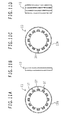
- Fig. 10 and Figs. 11A to 11D illustrate the electric water pump of an fourth embodiment.
- Fig. 10 is a sectional view of the axial side surface of the electric water pump of the fourth embodiment.
- Figs. 11A to 11D are views describing in detail the stator core as a core of the fourth embodiment.
- Fig. 11A is a front view of the stator core for one phase.
- Fig. 11B is a side view of the stator core for one phase.
- Fig. 11C is a rear view of the stator core for one phase.
- Fig. 11D illustrates the stator cores for three phases as they are positioned in the rotating direction and laminated together. It is to be notes that the same parts at those in the first embodiment are termed the same names and denoted by the same reference numerals.
- the fourth embodiment differs from the first embodiment in that the axial ends of the stator cores 13 are in close contact with the motor housing 12, and that a rotation stop mechanism is provided to restrict the relative rotation of the stator core 13 or the motor housing 12 adjacent to the axial end of each of the stator cores 13.
- the circular portion 13b on the side of the axial pump chamber 2 in the stator core 13 has recessed persons 37 which make up part of the rotation stop mechanism.
- the recessed portions 37 are provided as three grooves formed radially on both circumferential sides of each of the two adjacent claw base portions 13c. It is to be noted that the circumferential angle formed by the recessed portions 37 is such that the stator cores are spaced spart in the circumferential direction by an electrical angle of 120 degrees.
- a projected portion 38 which makes up the rotation step mechanism together with the recessed portions 37 is molded integrally on the circular portion 13b the side of the sealing plate 13b in the stator core 13.
- the projected portion 38 is located at the back of the recessed portion 37 in the middle of the three recessed portions 37 arranged in the circumferential direction.
- the projected portion 38 is provided engageably with the recessed potion 37 and has approximately the same shape as the same 37.
- the sealing plate 12b as the motor housing 12 has the recessed portion 37 which is provided engageably with the projected portion 38 of the stator core 13 at one circumferential location.
- a housing 3b which serves both as the motor and pump housings also has the projected portion 38 which is provided engageably with the recessed protion 37 of the stator core 13 at on circumferential location. It is to be noted that the recessed portions 37 and the projected portions 38 are formed almost in the same shape.
- the projected portion 38 of the of the stator cores 13 engages with the circumferentially outer one of the three recessed portions 37 of the adjacent stator core 13 as shown In Fig. 11D . Further, the recessed portion 37 of one of the stator cores 13 engages with the projected portion 38 of the housing 3b which serves both as the motor and pump housings. Still further, the projected portion 38 of one of the stator cores 13 engages with the recessed portion 37 of the sealing plate 12b.
- the stator cores for the plurality of phases are positioned in place by the rotation stop mechanism, thus permitting positive and easy positioning of the stator cores to a position corresponding to the desired electrical angle.
- the rotation stop mechanism includes the recessed and projected portions, providing increased contact area with the motor housing. This ensures heat removal from the motor housing which is cooled by the adjacent pump structural body, thus providing improved cooling effect.
- the recessed portions include grooves.
- the projected portions can be formed long in a rectangular shape, allowing for easier heat transfer.
- the plurality of recessed portions are provided on each of the stator cores. This allows for positioning of the stator cores to a circumferential position appropriate to the desired electrical angle, thus providing improved productivity.
- the rotation stop mechanism incudes the recessed and projected portions. Howler, separate members may be attached to the stator cores to stop the rotation.
- the recessed portions include grooves, and the projected portions rectangular protrusions.
- the recessed portions may include holes, and the projected portions circular protrusions. In this case, the area of the recessed and projected portions is smaller. However, this construction will reduce the impact on the magnetic circuit.
- stator cores have the same shape.
- stator cores may have the projected and recessed portions at different positions. This eliminates the need to provide the plurality of recessed portions. As a result, the impact on the magnetic circuit can be reduced if the projected and recessed portions are distributed in the circumferential direction.
- the motor housing 12 is provided.
- the motor housing can be omitted if the stator cores are clamped together axially by a fixing member such as bolts and a sealing member is provided for each of the stator cores to prevent cooling water leak. This permits parts count reduction, thus providing an inexpensive pump. It is to be noted that the number of sealing members can be reduced by increasing the number of areas integrally molded with resin.
Abstract
Description
- The present invention relates to an electric pump driven by an electric motor.
- Among measures to improve automobile fuel efficiency are firstly idling stop adapted to stop an engine when a vehicle stops, and secondly hybridization adapted to drive a vehicle using a rotary electric machine and an engine. These measures have already found commercial use. To use these systems, a drive source is additionally required for a pump in the case of an idling stop system the engine stops when the vehicle steps. In the case of hybrid vehicles, on the other hand, a water pump is required to cool the drive motor or starter-generator and its controller in addition to the idling stop system. As a result an electric pump using an electric motor is increasingly common as a drive source.
-
JP-A-2000-213490 - The electric motor adapted to drive the water pump described in
JP-A-2000-213490 - It is an object of the present invention to provide a compact electric pump with high mountability.
- The present invention is characterized in that a pump structural body is driven by an electric motor. The electric motor has a core with a plurality of first claw magnetic poles and a plurality of second claw magnetic poles, each extending from both axial ends of one member of the core toward the end of the other member of the core, The plurality of first claw magnetic poles and the plurality of second claw magnetic poles are formed alternatively in the circumferential direction of the core. A coli is wound around and along the core in a ring form.
- The present invention is further characterized in that a pump structural body is provided adjacent to at least one end of the stator core and a magnetic pole member to discharge a cooling medium.
- The present invention is still further characterized in that a pump structural body adapted to discharge a liquid is driven by an electric motor. The electric motor includes a molded portion, which is formed by molding of a non-magnetic material, at least on the inner periphery of the stator core which includes a comprised powder magnetic core,
- According to a first aspect of the present invention, an electric pump mounted in a vehicle comprises:
- an electric motor, said electric motor including
- a core having a plurality of first claw magnetic poles and a plurality of second claw magnetic poles, each extending from both axial ends of one member of said core toward the end of another member of said core, said plurality of first claw magnetic poles and said plurality of second claw magnetic poles formed alternatively in the circumferential direction;
- a coil wound around and along said core in a ring form, said coil generating different magnetic poles on said first and second claw magnetic poles as it is energized; and
- a magnetic pole member disposed to be opposed to said first and second claw magnetic poles and relatively rotatable with said core so that different magnetic poles are formed in the circumferential direction; and
- a pump structural body adapted to discharge a flowing medium as a rotational force is given to said pump structural body by said core or magnetic pole member.
- According to a second aspect of the present invention, the core is preferably formed to include a single phase, and magnetic field deviation portions are preferably provide on the first and second claw magnetic poles to deviate a magnetic field in one circumferential direction.
- According to a third aspect of the present invention, the magnetic field deviation portions are preferably provided so that one circumferential side of the first and second claw magnetic poles is farther from the magnetic pole member than the other circumferential side thereof.
- According to a fourth aspect of the present invention, the cores are formed to include a plurality of phases.
- According to a fifth aspect of the present invention, an electric pump which is adapted to discharge a cooling medium comprises:
- an electric motor, said electric motor including
- a coil wound in a ring form;
- a core formed along said coil in a tubular from so that different magnetic poles are formed alternately in the circumferential direction as said coil is energized; and
- a magnetic pole member disposed to be opposed to said magnetic pole forming portions of said core and relatively rotatable with said core so that different magnetic poles are formed in the circumferential direction; and
- a pump structural body disposed adjacent to at least one end of said core and magnetic pole member so that said pump structural body discharges a cooling medium as a rotational force is given to said pump structural body by said core or magnetic pole member.
- According to a sixth aspect of the present invention, the core and the magnetic pole member are preferably housed in a motor housing and one axial end of the motor housing preferably serves also as a pump housing adapted to house said pump structural body.
- According to a seventh aspect of the present invention, the side end portion of the pump structural body disposed along the inner periphery of the motor housing is in close contact with the core.
- According to an eighth aspect of the present invention, a rotation stop mechanism is preferably provided between the side end portion of the pump structural body disposed along the inner periphery of the motor housing and the core to restrict the relative rotation of the core.
- According to a ninth aspect of the present invention, the rotation stop mechanism preferably comprises a projected portion on one side and a recessed portion on the other side.
- According to a tenth aspect of the present invention, the cores are preferably formed to include a plurality of phases the rotation stop mechanism is preferably provided on said core for each phase.
- According to an eleventh aspect of the present invention, bearings for the magnetic pole member are preferably disposed along the inner periphery of the magnetic pole member.
- According to a twelfth aspect of the present invention, an electric pump which is adapted to discharge a liquid comprises:
- an electric motor, said electric motor including
- a coil wound in a ring form;
- a stator core formed along said coil in a tubular form and made from a compressed powder core so that different magnetic poles are formed alternately in the circumferential direction as said coil is energized, said core having a molded portion, formed by molding a non-magnetic material, at least on the inner periphery thereof; and
- a rotor disposed to be opposed to said magnetic pole forming portions of said stator core so that different magnetic poles are formed in the circumferential direction, said rotor rotating in a liquid: and
- a pump structural body adapted to discharge a liquid as a rotational force is given to said pump structural body by said rotor.
- According to a thriteenth aspect of the present invention, the non-magnetic material is preferably a resin material.
- According to a fourteenth aspect of the present invention, the molded portion is preferably provided over the entire inner periphery of said stator core.
- According to a fifteenth aspect of the present invention, the non-magnetic material and the magnetic pole are preferably formed alternately on the inner peripheral surface of said stator core.
- According to a sixteenth aspect of the present invention, the stator cores are preferably formed to include a plurality of phases and the molded portion is preferably formed on the core for each phase.
- According to a seventeenth aspect of the present invention, channels are preferably provided on said molded portion.
- According to an eighteenth aspect of the present invention, the channels are preferably formed radially.
- According to a nineteenth aspect of the present invention, the stator cores are preferably formed to include a plurality of phases, where in the molded portion is preferably formed on said core for each phase, and a channel is preferably provided between the phases.
- According to a twentieth aspect of the resent the channel is formed at the center of said magnetic pole.
- The present invention makes it possible to reduce the size of an electric motor as a whole because of absence of coil ends, thus providing significantly improved mountability.
-
-
Fig. 1 is a sectional view of the axial side surface of an electric water pump according to a first embodiment of the present invention; -
Figs. 2A to 2D are views describing in detail a stator core for one phase and a coil according the first embodiment of the present invention; -
Fig. 3 is a sectional view along line A-A of theFig. 1 ; -
Fig. 4 is an explanatory view of a vehicle with the electric pump; -
Figs. 5A to 5C illustrate the electric water pump of a second embodiment; -
Fig. 6 is a sectional view of the axial side surface of the electric water pump according to a third embodiment of the present invention; -
Figs. 7A and 7B are views describing in detail the stator core and the coil according to the third embodiment of the present invention; -
Fig. 8 is a diagram showing a control configuration according to the third embodiment of the present invention; -
Figs. 9A to 9G are graphs illustrating the operating principles of the third embodiment; -
Fig. 10 is a sectional view of the axial side surface of the electric water pump according to a fourth embodiment of the present invention; and -
Figs. 11A to 11D are views describing in detail the stator core of the fourth embodiment of the present invention. - Embodiments of an electric water pump of the present invention will be described with reference to the accompanying drawings;
-
Figs. 1 to 3 illustrate an electric motor of a first embodimentFig. 1 is a sectional view of the axial side surface of the electric water pump of the first embodiment.Figs. 2A to 2D are views describing in detail a stator core for one phase and a coil of the first embodiment.Fig. 2A is a perspective view of the partial section of the stator core and the coil.Fig. 2B is a front view of the stator core.Fig. 2C is a developed view, in the circumferential direction, of the inner periphery of the stator core as seen from the inside.Fig. 2D is a sectional view of the partial side of the stator core and the coil.Fig. 3 is a sectional view along line A-A ofFig. 1 . - The electric water pump is designed primarlly for use in hybrid vehicles driven by an engine and a drive electric motor in combination so as to cool the drive electric motor or the starter-generator and its controller and other devices.
- In
Fig. 1 , a water pump unit 1 as a pump structural body uses a centrifugal pump. The water pump unit 1 includes apump housing 3 with a pump chamber 2 and an impeller 4 rotatably housed in the pump chamber 2. - The
pump housing 3 is formed by die-casting with an aluminum alloy, a metallic material with high thermal conductivity. As shown inFig. 3 , the pump chamber 2 is formed inside thepump housing 3 so that the inner diameter thereof increases gradually depending on the circumferential position. As a result, thepump housing 3 is divided axially into two members or members 3A and 3B. The members 3A and 3B are combined into a single piece by bolts 6 after the insertion of the impeller 4 and adrive shaft 5. Further, as shown inFig. 1 , a tubular suction portion 7 is formed to project outward from the approximate center of the pump chamber in the axial direction. A tubular bearing support portion 8 is formed to project toward anelectric motor unit 11 from the approximate center of the pump chamber in the axial direction. Further, as shown inFig. 3 , a discharge portion 9 is formed near the position where the inner diameter of the pump chamber 2 is largest. It is to be noted that a flowing medium discharged from the discharge portion 9, or more specifically cooling water as a cooling medium, is a freeze-resistant liquid (antifreeze) prepared by adding ethylene glycol to water, with its anticorrosion effect also improved. This cooling water is supplied to the drive electric motor and its inverter of a hyb rid vehicle. - The impeller 4 in the pump chamber 2 includes an umbrella disk-shaped plate on the side of the suction portion 7, an umbrella disk-shaped plate on the side of the
electric motor unit 11, and a plurality of blades (eight blades in the present embodiment) arranged radially therebetween. The impeller 4 is integrally molded by injection molding with resin material. Ahole 10 is provided at the approximate center of the impeller 4, Themetal drive shaft 5 in a hollow cylindrical form is press-fitted into thehole 10 and secured in place so that thedrive shaft 5 and the impeller 4 rotate integrally. - With the water pump unit 1 thus constructed, the impeller 4 rotates as the
drive shaft 5 rotates, permitting cooling water scraped out by the blades to flow to the outer peripheral side by centrifugal force. Cooling water thus permitted to flow to the outer peripheral side is guided along the inner peripheral surface of the pump chamber 2 into the discharge portion by inertial force. It is to be noted that negative pressure is present in the proximity of the suction portion 7 because cooling water on the impeller 4 flows to the outer peripheral side. As a result, cooling water flows in through the suction portion 7. Therefore, the pump chamber 2 is filled with cooling water at least during the rotation of the impeller 4. - Next, a description will be made of the
electric motor unit 11 provided adjacent to the water pump unit 1 with reference toFig. 1 andFigs. 2A to 2D . - The
electric motor unit 11 includes amotor housing 12 having a housing portion therein andstator cores 13 as cores, housed in the motor housing and adapted to generate a magnetic field as they are energized. Theelectric motor unit 11 also includescoils 14 housed in thestator cores 13 and arotor 16 as a magnetic pole member havingpermanent magnets 21 arranged to be opposed to the stator. - The
motor housing 12 has a housing portion 12a in a hollow cylindrical form and asealing plate 12b adapted to seal one end of the housing portion 12a. The two portions are combined into one piece bybolts 15. Further, the opening at the other end of the housing portion 12a is sealed with thepump housing 3 by the bolts 6. As a result, part of thepump housing 3 also serves as themotor housing 12. It is to be noted that the housing portion 12a and the sealingplate 12b are formed by die-casting with aluminum alloy as with thepump housing 3. The sealingplate 12b has abearing support portion 17 in a hollow cylindrical form which projects toward the side of the water pump unit. Thebearing support portion 17 is integrally molded as with the bearing support portion 8 of thepump housing 3 so as to be opposed to the bearing support portion 8. - The inner periphery of the bearing support portion 8 of the
pump housing 3 and that of thebearing support portion 17 of the motor hosing 12 have each a large and small diameter portions formed axially in a stepped form.Resin bushings 18 as bearings, that is to say sliding bearings, are press-fitted into the large diameter portion. Thebushings 18 are axially positioned as they touch the small diameter portion. Further, thesebushings 18 have each a disk-shaped flange portion which is integrally molded at the end on the side where the two bushings face each other. - Next, the
stator core 13 and thecoil 14 will be described, In the present embodiment, a three-phase brushless motor is used which has thestator cores 13 for three phases and thecoils 14, Therefore, the threestator cores 13, each housing thecoil 14, are disposed in a laminated fashion and electrically insulated from one another in themotor housing 12 so as to be arranged side by side in the axial direction. - A description will be made of one of the three phases. The
stator core 13 includes a ring-shaped member divided into two members at the approximate center in the axial direction, One of the two ring-shaped members is in the form of a claw tooth (claw magnetic pole). More specifically, this member includes an outerperipheral portion 13a which extends axially on the outermost periphery and a hollow disk-shapedcircular portion 13b which is provided at the end of the outer peripheral portion. The member also includes a plurality ofclaw base portions 13c (12 portions in the present embodiment) which extend from the circular portion toward the inner periphery approximately at equal intervals therebetween and a plurality ofclaw portions 13d which extend axially from theclaw base portions 13c toward the counterpart ring-shaped member in a tapered shape, that is to say approximately in a trapezoidal shape. - As shown in
Figs. 2A and 2D , thestator core 13 is formed so that the cross section thereof is approximately in the shape of letter U. Theclaw portion 13d is longer than the outerperipheral portion 13a. Theclaw portions 13d and theclaw base portions 13c are connected continually on the inside in the shape of a circular arc. It is to be noted that the claw pole includes theclaw base portion 13c and theclaw portion 13d. - The two ring-shaped members of substantially the same shape thus constructed are combined into the
stator core 13 for one phase by molding. In the molding, the two members are arranged to be opposed to each other so that theclaw portions 13d of the two members are disposed alternately. Then the entire surface other than theclaw portions 13d is molded with anon-magnetic resin material 19. In this process, thecoil 14 is placed thereinside which is wound around the ring-shaped members in the shape of a circular are (in a toroidal shape). It is to be noted that thecoil 14 is insulation coated. It is also to be noted that the two ends thereof are drawn out from the opposed surfaces of the ring-shaped members for energization and connected to an inverter for current control. - In hybrid and other vehicles, a high supply voltage is used, making it necessary to dispose an insulator between the
coil 14 and thestator core 13. If a low supply voltage is used (as low as 12V in ordinary automobiles), however, thecoil 14 may be disposed directly on thestator core 13. - It is to be noted that since the present embodiment uses a three-phase motor, the
stator cores 13 of phases U, V and W are housed in themotor housing 12 by press-fitting and secured in place. In themotor housing 12, thestator cores 13 are arranged side by side in the axial direction so that theclaw portions 13d are shifted in the circumferential direction by an electrical angle of 120 degrees. Thecoils 14 are each connected to a three-phase inverter. On the other hand, since theclaw portions 13d are spaced apart in the circumferential direction by an electrical angle of 120 degrees, thecoils 14 of the three phases can be wound in the same direction. As a result, all thestator cores 13 can be constructed with completely identical components. It is to be noted that thestator cores 13 have each a resin material molded on the surface. Therefore, each thereof is attached in insulated fashion to themotor housing 12. However, a space is formed between thepump housing 3 and the sealingplate 12b of themotor housing 12. - The
aforementioned stator cores 13 are each made from a compressed powder core formed by compression molding of iron powder which is a magnetic powder coated with a non-magnetic substance. Higher strength can be achieved by causing a binding agent to reside between iron powder particles. - On the other hand, a space is provided between the claw magnetic poles of the two ring-shaped members of the
stator core 13 to reduce the inductance of thecoil 14, as shown inFig. 2C . Thenon-magnetic resin material 19 is also molded in the space between the claw magnetic poles. Theresin material 19 is not molded on the inner peripheral surface of theclaw portions 13d. As a result, theresin material 19 and theclaw portions 13d are arranged alternately on the inner peripheral surface of thestator core 13. - Next, the
rotor 16 as a magnetic member will be described. Therotor 16 includes thedrive shaft 5 secured to the impeller 4 so as to be integrally rotatable, arotator core 20 secured to thedrive shaft 5 andpermanent magnets 21 disposed on the outer periphery of therotator core 20 Therotator core 20 is formed by integral molding of a cylindrical magnet attachment portion 20a which is disposed on the outer periphery and a drive shaft attachment portion 20b using a magnetic steel material. The drive shaft attachment portion 20b is narrower than the magnet attachment portion 20a and disposed at the approximate center of the same 20a. In other words, the two portions are molded so that the axial cross-section is approximately in the shape of letter H. Further, a hole 20c is formed on the inner periphery of the drive shaft attachment portion 20b. As thedrive shaft 5 is press-fitted into the hole 20c, therotator core 20 and thedrive shaft 5 are secured together so as to be integrally rotatable. Still further, the plurality of rod-shapedpermanent magnets 21 extending in the axial direction are secured in the direction on the outer periphery of the magnet attachment portion 20a. Thepermanent magnets 21 are arranged so that the magnetic poles of every two adjacent magnets are different from each other. - The
rotor 16 thus consturcted is disposed so that the inner peripheries of thestator cores 13 and thepermanent magnets 21 are opposed to each other. Thedrive shaft 5 is rotatably supported by the twobushings 18. Thedrive shaft 5 is pervented from moving in the axial direction by flange portions of the twobushings 18. - Further, cooling water is introduced toward the
rotor 16. for example, through the gap between thedrive shaft 5 and thepump housing 3, along the inner periphery of thedrive shaft 5 and through the gap between the inner periphery of thebushings 18 and the outer periphery of thedrive shaft 5. As a result, therotor 16 rotates in cooling water. At this time, cooling water is constantly introduced between thebushings 18 and thedrive shaft 5, thus allowing to construct smooth sliding bearings. - Next, the operation of the
electric motor unit 11 thus constructed will be described below. - The
coils 14 are supplied with current from a power source such as battery via the three-phase inverter. As a result, different magnetic poles are generated on first and second claw magnetic poles, the first claw magnetic pole extending from one of the ring-shaped member of thestator core 13, the claw magnetic pole extending form the other ring-shaped member. For example, if N pole is generated on the first claw magnetic pole, S pole is generated on the second claw magnetic pole. In the present embodiment, thecoils 14 have the phases U, V and W. This makes it possible to regulate energization of each of the coils, thus switching the magnetic poles as if they rotate. As a result, thepermanent magnets 21 on therotor 16 which are opposed to the claw magnetic poles move in the rotational direction together with magnetic fields generated by the claw magnetic poles. This causes therotor 16 to rotate. It is to be noted that the rpm of thedrive shaft 5 can be controlled by controlling the energization of thecoils 14 of the phases U, V and W. - To control the rotation of the
rotor 16, detection of the position of the same 16 is normally required by a magnetic pole position detector. However, the present embodiment uses the induced voltage position detection method adapted to detect the magnetic pole position from the voltage induced in thecoil 14, thereby switching the energization of thecoils 14 of the three phases. That is to say, the present embodiment uses a sensorless method to defect the position of therotor 16. It is to be noted that the load change of the impeller 4 of the water pump unit is slow. As a result, the use of such a method is sufficiently possible. - Although the present embodiment has been described to cool the drive electric motor or the starter-generator and its controller in hybrid vehicles, the invention may be used as a pump to cool the engine or warm the cabin. Here, a vehicle with the electric pump will be described with reference to
Fig. 4 . A hybrid vehicle will be described as an example. - In
Fig. 4 , the engine room of avehicle 22 has anengine 23 coupled via a transmission (not shown) towheels 24 which drive the vehicle. Here, cooling water supplied by a firstelectric pump 25 removes heat from theengine 23 to cool theengine 23. Cooling water is cooled down as it releases heat removed from theengine 23 via athermostat 26 to aradiator 27 and returns to the firstelectric pump 25. On the other hand, cooling water supplied by a second electric pump 28 cools an inverter 29 and a travelingmotor 30. Then cooling water is cooled down by theradiator 27, shared by cooling water from the firstelectric pump 25, and returns to the second electric pump 28. Further, cooling water supplied by a third electric pump 31 is introduced into part of water circulated by the firstelectric pump 25 to release heat from theengine 23 into the cabin by a cabin heater 32 and returns to the riginal flow path. It is to be noted that abypass channel 33 is provided to allow the cooling medium to bypass theradiator 27 if thethermostat 26 determines that theengine 23 has not warmed up. - Next, the operation and effects of the present embodiment will be described.
- In the present embodiment, the coils are wound around and along the cores in a ring shape, thus eliminating coil ends which would otherwise not contribute to generation of a torque. This makes it possible to bring the cores and the pump structural body closer together to the extent possible, thus permitting size reduction and thereby providing improved mountability.
- It is to be noted that when these pumps are mounted in a vehicle, the engine room which will accommodate the pumps is a crowded space with a variety of parts housed therein. In particular, recent years have seen a drastic increase in the number of parts mounted in the engine room because, for example, of hybridization and functional improvement. As a result, there is a growing tendency to require the parts accommodated therein to be smaller and lighter than parts accommodated in other rooms. In light thereof, it is extremely beneficial to use pumps as those described above.
- Such electric pumps are finding wider use as shown in
Fig. 4 . These pumps have two advantages. One of the advantages is that the pumps occupy a smaller space in the engine room thanks to size reduction. The other advantage is that the inverter and the traveling motor of hybrid vehicles can be reduced in size because of higher power output of the electric pumps, thus contributing to improved layout flexibility and, in a broader sense, improved vehicle performance. Thus, these electric pumps are advantageous not only as pumps alone but also in terms of the vehicle as a whole. - In addition, the coils are easy to be manufactured. Besides, they are easier to be molded after being wound around the cores as compared to coils wound around laminated cores. This ensures a high proportion of space occupied by the coils in the coil housing space, thus reducing coil resistance and thereby providing a motor with high efficiency. Further, improved occupancy ratio ensures reduced thermal resistance between the coils and cores, thus rendering the drive motor capable of withstanding a large load. Conversely these advantages can be taken advantage of to reduce the size and weight of the motor. Still further, the length of one turn of coil can be reduced, thus providing reduced resistance and ensuring higher motor efficiency.
- In the present embodiment, multiphase cores are used, ensuring easy and positive control.
- In the present embodiment, the pump structural body is disposed adjacent to at least one end of the core and magnetic pole member so that the pump structural body discharges a cooling medium. This ensures effective cooling of the cores and magnetic member.
- In the present embodiment, no coil end is present, making it possible to provide a pump housing at one axial end of the motor housing. This improves the cooling effect. In this case, other effects can also be achieved, including reduction In parts, size reduction and weight reduction.
- In the present invention, the pump and motor housings are molded with the same material, thus ensuring efficient cooling. In particular, the use of aluminum alloy, a material with high thermal conductivity, provides added cooling effect.
- In the present embodiment, the bearings of the magnetic pole member are disposed along the inner periphery of the magnetic pole member. This provides a shorter axial length of the pump while securing appropriate bearing lengths, thus contributing to size and weight reduction. In particular, the rotor core as a magnetic member has a large enough margin in terms of magnetic flux produced. Therefore, it is possible to reduce the axial length of the pump and dispose ths sliding bearings inside the rotor.
- In the present embodiment, the cores are made of compressed powder cores, thus allowing easy manufacture of complicated three-dimensional shapes. Further, the compressed powder core is one piece as a whole in contrast to a conventional laminated core manufactured by punching out thin steel sheets. As a result, this core is structurally rigid and difficult to vibrate, thus keening noise low. When constructed in the aforementioned shape, the core can be made into a motor offering further reduced vibration and noise. Still further, the core can be molded with a necessary raw material, thus providing a material utilization ratio of 100% and keeping manufacturing cost low.
- In the present embodiment, the stator cores as cores are molded with a non-magnetic material, thus providing enhanced strength even if the stator cores are made from compressed powder cores. Further, the cores can be improved in durability so as to prevent corrosion of the coils as cooling water as liquid is introduced therein. Still further, the stator cores can be readily sealed so as to prevent external cooling water leakage. As a result, there is no need to provide a cooling medium shield separately between the stator cores and the rotor as is conventionally practiced. Instead, the stator cores can be formed directly on the stator surfaces facing the rotor. This reduces the magnetic gap, thus preventing a reduction of torque resulting from an increased gap length due to the presence of a shield, that is to say low efficiency and other problems. Therefore, not only size and weight reduction but also high efficiency can the achieve. In particular, the use of resin, a non-magnetic material, will prevent corrosion and other problems caused by cooling water.
- In the present embodiment, the inner peripheral surfaces of the stator cores are constructed so that the non-magnetic material and the magnetic poles are formed alternately in the circumferential direction. This allows the stator cores to be located on the stator surfaces facing the rotor, thus reducing the magnetic gap length and providing improved motor characteristics. Further, enhanced cooling effect of the stator cores will be achieved.
- In the present embodiment, cooling water as cooling liquid is introduces into the stator cores and the ends thereof. This ensures efficient cooling of not only the stator cores and coils but also the rotor with coling water. Such an effective removal of heat also allows for a compact, lightweight and highly efficient construction. Further, the rotor is supported by bearings in cooling water, allowing of smooth supporting of the rotor with inexpensive sliding bearings. In particular, the drive shaft is hollow so that cooling water is readily introduced into the two bearings, thus ensuring further smooth supporting of the rotor.
- In the present embodiment, the claw portions of the cores are inclined in a tapered shape. This reduces cogging torque of the motor and brings the waveform of the coil induced voltage closer to a sine wave. As a result, supplying a sine wave current produces a constant torque from the three phases with minimum pulsation in the rotational direction. This provides low motor noise.
- Thus, in the present embodiment, an electric water pump has been described as an example of electric pump. The present invention is also applicable, for example, to a power steering pump adapted to supply oil to a hydraulic power steering system, oil pumps such as lubricating pump adapted to supply lubricating oil to the engine, a compressor which uses a gas as its cooling medium and an electric oil pump which uses oil as its cooling medium. However, the present invention is more useful for use as a pump adapted to discharge a cooling medium as it is capable of efficiently cooling the electric motor unit. It is to be noted that the pump unit need not necessarily be a centrifugal pump. Instead, it may be a vane pump, gear pump, plunger pump, and so on.
- In the present embodiment, the pump and motor housings are formed with the same material. The two housings share a part thereof. However, the two housings may be formed with different materials and separately. This allows for selection of materials suited for application. The pump and motor housings need not necessarily be made of a metallic material. Selection of a resin material is also possible. A resin material with high thermal conductivity such as unsaturated polyester will provide effective cooing.
- In the present embodiment, an impeller made of a resin material is used. However, the impeller may also be formed by metal stamping, die-casting or casting of a metallic material. This will enhance the impeller strength,
- In the present invention, the impeller and the drive shaft are constructed with separate members. However, they may be integrally molded. This will reduce the parts count.
- In the present embodiment, metal bushings are used to support the drive shaft. However, resin bushings may also be used. Further, needle or ball bearings may also be used. It is to be noted that if needle or ball bearings are used, they should be kept away from cooling water to the extent possible. A seal is required to prevent cooling water from flowing back and forth between the pump unit and the electric motor unit. In this case, the rotor does not rotate in cooling water, but does in air. It is preferable that grease or other lubricating oil be applied to the bearings for lubrication.
- In the present embodiment, the cores remain stationary whereas the rotor with permanent magnets as magnetic members rotates. However, a so-called DC motor may also be used in which the sore rotates as the rotor as the coil is supplied with current from a brush whereas the permanent magnets regain stationary as the stator, Further, a so-called induction motor may also be used in which a separate core and coil are used in place of the permanent magnets.
- In the present embodiment, the stator cores are made from compressed powder cores, However, the stator cores may be formed by cutting or stamping The cores formed by such processes can be enhanced in strength as compared to composed powder cores.
- In the present embodiment, the non-magnetic material and the magnetic poles are formed alternately on the inner peripheries of the stator cores in the circumferential direction. However, the entire inner peripheries of the same may be molded. This will prevent corrosion of the stator cores caused by cooling water.
- In the present embodiment, the electric motor unit and the controller thereof such as inverter are provided separately. However, they may be formed integrally and disposed at the end of the motor housing on the side opposite to the pump housing. This will provide an electric motor of more compact construction.
- In the present embodiment, the induced voltage position detection method, a sensorless method, is used to detect the rotor position. However, the provision of a magneto pole position detector will provide a reduced startup time.
- In the present embodiment, the stator cores are molded phase by phase, after which they are scoured in the motor housing. However, the stator cores may be secured in the motor housing first and then molded together with the motor housing.
- In the present embodiment, a resin molded portion and a space are provided between the stator cores and the pump housing. However, if the pump housing is made of a non-magnetic material such as aluminum alloy, the stator cores and the pump housing may be directly in contact with each other. This allows heat from the coils to directly escape to the refrigerant via the pump housing, thus providing enhanced cooling effect and permitting size and weight reduction. Farther, the resin molded portion may be eliminated so that only a space is provided between the stator cores and the pump housing. If, as a result of this construction, the refrigerant can be brought in direct contact with the side surfaces of the stator cores, heat will be able to escape directly from the stator windings via the stator cores to the refrigerant, thus permitting further size reduction.
- In the present embodiment, the stator cores of the phases U, V and W are spaced apart in the circumferential direction by an electrical angle of 120 degrees. However, the stator cores may be spaced apart in the circumferential direction by an electrical angle of 60 degrees, In this case, the phase sequence is U, W and V. The coil of the phase W at the center must be wound in the reverse direction.
- In the present embodiment, the claw portions of the cores are inclined in a tapered shape. However, they may be parallel to each other in the axial direction.
-
Figs. 5A to 5C illustrate the electric water pump of a second embodiment.Fig. 5A is a sectional view of the axial side surface of the electric water pump as the second embodiment.Fig. 5B is a sectional view along line B-B ofFig. 5A. Fig. 5C is a side view of only the stator cores molded with a resin which is a non-magnetic material. It is to be noted that the same parts as those in the first embodiment are termed the same names and denoted by the same reference numerals. - The second embodiment differs from the first embodiment in that the molded
portion 19 of thestator cores 13 molded with a resin, a non-magnetio material, is provided withchannels 34 through which cooling water as a cooling medium can flow. - As shown in
Fig. 5B , thechannels 34 includechannels 34a, 34b and 34c. Thechannel 34a is an annular channel provided in an annular shape at the approximate center of the circular portion in the direction of radius on the axial end surface of thestator cores 13. The channels 34b are radial channels provided radially, each located at the center of one of the magnetic poles, that is to say at the approximate center of each of theclaw base portions 13c in the circumferential direction. The channels 34c are axial channels as shown inFig. 5C , each extending from each of the radial channels approximately in the axial direction on the axial side surfaces of thestator cores 13. Thechannels 34 are formed on the two end surfaces and the side surfaces of thestator cores 13 of the three phases. These channels are molded by the mold used for injection molding of resin. Each cf thestator cores 13 has the same channels as the other cores. As a result, when thestator cores 13 of the three phases are axially arranged side by side, the identically shaped annular andradial channels 34a and 34b of the adjacent cores are brought face to face. The channels 34c of the adjacent cores are also located at the same positions, permitting communication between the channels 34c. - As described above, in the present embodiment, the
channels 34 permit cooling water to fill into the inner peripheral sides of thestator cores 13, thus providing improved cooling effect. - In the present embodiment, some radial channels are provided, thus ensuring effective distribution of cooling water.
- In the present embodiment, some channels are provided between the stator cores, thus allowing for cooling of each of the cores.
- In the present embodiment, some channels are formed, each at the center of one of the magnetic poles, thus allowing for cooling of the locations most needed to be cooled.
- In the present embodiment, the molded portion of each of the stator cores has annular and axial channels. As a result, cooling can be accomplished between the stator cores, between the stator cores and the pump housing and between the stator cores and the motor housing. This permits distribution of the refrigerant all around the electric motor, thus providing further improved cooling effect and an even more compact motor.
- In the present embodiment, the rotor is rotatably disposed to face the inner peripheries of the stator cores. As a result, when the rotor rpm is high, cooling water flows into the areas of the inner peripheries of the stator cores opposed to the rotor. The pressure drops with increase in flow rate. This creates a pressure difference between the pump housing and motor housing sides of the stator cores not opposed to the rotor. As a result, cooling water circulates through the channels. This provides further improved cooling effect.
- In the present embodiment, the channels provided on all the molded portions of the stator cores are identically shaped. This permits molding of the channel with a single mold, thus providing an inexpensive pump.
- In the present embodiment described above, the channels are formed with a mold. However, the channels may be formed by cutting.
- In the present embodiment, annular channels are provided. However, if these channels are omitted, all the channels can be formed by molding the plurality of stator cores in a single step.
-
Fig. 6 andFigs, 7A and 7B illustrate the electric water pump of a third embodiment.Fig. 6 is a sectional view of the axial side surface of the electric water pump of the third embodiment.Figs. 7A and 7B are views describing in detail the stator core and coil of the third embodiment.Fig. 7A is a perspective view of the partial section of the stator core as a core and ths coil of the third embodiment.Fig. 7B is a front view of the stator core. It is to be noted that the same parts as those in the first embodiment are termed the same names and denoted by the same reference numerals. - The third embodiment differs from the first embodiment in that a single-phase motor is used which includes the single-
phase stator core 13. The third embodiment also differs in that a steppedportion 35 is provided on one circumferential side of each of theclaw portions 13d of the claw magnetic poles. The third embodiment also differs in that aposition detector 36 is provided to detect the rotor position. - The
stator core 13 is almost identical to one of thestator cores 13 extracted from the first embodiment. In theformer stator core 13, however, each of theclaw portions 13d of the claw magnetic poles extending from both ends of thestator core 13 has the steppedportion 35, as shown inFigs. 7A and 7B . The steppedportions 35 are provided as magnetic field deviation portîons to deviate a magnetic field in one circumferential direction. These portions are provided on the same side so that one circumferential side is farther from the rotor than the other circumferential side. The steppedportions 35 each have a step at the approximate center in the circumferential direction of the claw portion. - As shown in
Fig. 6 , theportion detector 36 is installed in a depressed portion which is provided on the inside at the end of themotor housing 12 on the side opposite to the pump. Theposition detector 36 detects leak magnetic flux of thepermanent magnet 21. on therotor 16, thus detecting the position of thepermanent magnet 21, that is to say the position of therotor 16. - Next, a description will be made of the control configuration of the single-phase motor of the third embodiment with reference to a control configuration diagram of
Fig. 8 . - In
Fig. 8 , the single-phase motor includes theelectric motor unit 11, a converter CONV adapted to supply AC power from a DC power supply Edc to theelectric motor unit 11, and a control circuit CONT adapted to control the converter CONV. - Here, the control circuit CONT includes an angle converter A which converts the output from the
position detector 36 into angle information, a speed control circuit B, and a converter output circuit C. In this configuration, the angle converter A receives information about leak magnetic flux of thepermanent magnet 21 from theposition detector 36 and outputs rotor position information based on the received information. Measuring the period of electric angle in a half cycle of the output signal from theposition detector 36 makes it possible to determine the rotor position information and the energization direction, that is to say whether to turn on positive or negative switching device of the converter CONV. The speed control circuit B calculates an error speed based on an externally given speed command Ns and the aforementioned speed information, The speed control circuit B submits the error to proportional-integral and other control before sending a control output to the converter output circuit C. This allows to control the converter CONV including an H bridge, thus controlling the speed to the target speed specified by the speed command Ns. - The above control is intended for fans and pumps. The response frequency for this control is extremely low or several hertz or less. As a result, the control is performed on a stable manner.
- Next, a description will be made of the operating principle and the operation at constant rotation speed of the single-phase motor of the third embodiment with reference to waveforms in
Figs. 9A to 9G . - In the waveforms of
Figs. 9A to 9G , the horizontal axis represents a position θ of therotor 16 in the range from 0 to 360 degrees in electrical angle.Fig. 9A illustrates an output signal of theposition detector 36.Fig. 9B illustrates a voltage Vt(θ) applied to thecoil 14 of the electric motor.Fig. 9C illustrates a voltage VO(θ) induced across thecoil 14 by the magnetic flux of thepermanent magnet 21.Fig. 9D illustrates a coil current iw (θ). The coil current iw (θ) is determined by the voltage Vt(θ) inFig. 9B , the induced voltage VO (θ) inFig, 9C , and a resistance r and an inductance L of thecoil 14 using the following formula:
where: ps is d/dt. -
Fig. 9E illustrates a cogging torque Tc (θ) generated between thestator core 13 and thepermanent magnet 21 when there is no current flow.Fig. 9F illustrates a torque, TOw (θ) generated by the induced voltage and the coil current. An output POw (θ) expressed by the product of the Induced voltage VO (θ) inFig. 9C and the current iw (θ) inFig. 9D represents the output produced by the magnetic flux of thepermanent magnet 21 and the coil current. If an angular velocity ω of therotor 16 is constant, the torque TOw (θ) is given by the following formula:
Fig. 9G illustrates a total torque T (θ) of the electric motor. This torque is the sum of the torque TOw (θ) generated by the induced voltage and the coil current and the cogging torque To (θ) and given by the following formula:
- If the angular velocity ω of the
rotor 16 is constant, the total torque will have the same waveform as the output torque. - The cogging torque of the single-phase motor exhibits a waveform as shown in
Fig. 9E relative to the rotating position because of the stepped portions intentionally provided only on one side of the surface of each of theclaw portions 13d of thestator core 13. Next, a description will be made of the torque TOw (θ) generated by the induced voltage and the coil current. The torque TOw (θ) makes up the main torque of the single-phase electric motor. First, the induced voltage generally exhibits a rectangular waveform as shown inFig. 9C . If the polarity of the applied voltage is switched at the zero-cross point at the output signal of a Hall device, as shewn inFig. 9A , which is disposed at a position slightly leading the induced voltage (the output signal of the Hall device is shaped into a sine wave by moving the Hall device away from the permanent magnet), the voltage as shown inFig. 9B is applied to thecoil 14. As a result, the current shown inFig. 9D flows, causing a torque to be generated by the current flowing into thecoil 14 and the voltage induced thereacross as shown inFig. 9F . This output exhibits the waveform as shown inFig. 9F as the induced voltage dips twice to near zero over a range of 360 degrees in electric angle. These voltage dips occur due to the operating principle of the single-phase drive motor. If these dips and the positive components of cogging torque are added together, a nearly uniform torque can be produced as a whole. - As described above, the motor of the present embodiment is a single-phase motor, allowing for significant reduction in parts count and thereby making the pump inexpensive. Further, although not producing a uniform torque as by a three-phase motor, the single-phase motor can be rendered capable of producing a comparably flat torque. This torque non-uniformity can be eased by changing the angle by which the applied voltage leads the induced voltage and by changing the applied voltage waveform. These changes can be accomplished by causing the applied voltage to increase smoothly at the leading edge and to decline gradually at the tralling edge. Another factor involved is conformity between the cogging torque waveform and that of the torque generated by the induced voltage and the coil current. The output torque can be made that relative to the rotor angle θ by generating the cogging torque optimally in the recessed position on the claw portion surface.
- In the present embodiment, an H-bridge control circuit can be used, thus reducing the number of switching devices to only two. This ensures simple circuit configuration includigng gate circuits, providing a controller configured at low cost.
- As described above, in the present embodiment, the stepped portions are provided on the claw portions as magnetic field deviation portions. However, these portions need not be stepped as long as one circumferential side thereof is farther from the rotor than the other circumferential side thereof. For example, one circumferential side of the claw portion may be smoothly thicker than the other circumferential side thereof. Further, the claw portion thickness In the circumerental direction may be the same. In this case, a material highly permeable to magnetic flux may be provided on one circumferential side of the claw portion, and a material not highly permeable on the other circumferential side thereof. Still further, the claw protion may be made of different materials in the circumferential direction so as to change the amout of passing magnetic flux in the circumferential direction. These constructions eliminate steps, ensuring lounger mold life.
-
Fig. 10 andFigs. 11A to 11D illustrate the electric water pump of an fourth embodiment.Fig. 10 is a sectional view of the axial side surface of the electric water pump of the fourth embodiment.Figs. 11A to 11D are views describing in detail the stator core as a core of the fourth embodiment.Fig. 11A is a front view of the stator core for one phase.Fig. 11B is a side view of the stator core for one phase.Fig. 11C is a rear view of the stator core for one phase.Fig. 11D illustrates the stator cores for three phases as they are positioned in the rotating direction and laminated together. It is to be notes that the same parts at those in the first embodiment are termed the same names and denoted by the same reference numerals. - The fourth embodiment differs from the first embodiment in that the axial ends of the
stator cores 13 are in close contact with themotor housing 12, and that a rotation stop mechanism is provided to restrict the relative rotation of thestator core 13 or themotor housing 12 adjacent to the axial end of each of thestator cores 13. - As shown in
Figs, 11A and 11B , thecircular portion 13b on the side of the axial pump chamber 2 in thestator core 13 has recessedpersons 37 which make up part of the rotation stop mechanism. The recessedportions 37 are provided as three grooves formed radially on both circumferential sides of each of the two adjacentclaw base portions 13c. It is to be noted that the circumferential angle formed by the recessedportions 37 is such that the stator cores are spaced spart in the circumferential direction by an electrical angle of 120 degrees. - As shown in
Figs. 11B and 11C , a projectedportion 38 which makes up the rotation step mechanism together with the recessedportions 37 is molded integrally on thecircular portion 13b the side of the sealingplate 13b in thestator core 13. The projectedportion 38 is located at the back of the recessedportion 37 in the middle of the three recessedportions 37 arranged in the circumferential direction. The projectedportion 38 is provided engageably with the recessedpotion 37 and has approximately the same shape as the same 37. - Further, as shown in
Fig. 10 , the sealingplate 12b as themotor housing 12 has the recessedportion 37 which is provided engageably with the projectedportion 38 of thestator core 13 at one circumferential location. Ahousing 3b which serves both as the motor and pump housings also has the projectedportion 38 which is provided engageably with the recessedprotion 37 of thestator core 13 at on circumferential location. It is to be noted that the recessedportions 37 and the projectedportions 38 are formed almost in the same shape. - In the engagement of the recessed
portions 37 with the projectedportions 38 thus provided, the projectedportion 38 of the of thestator cores 13 engages with the circumferentially outer one of the three recessedportions 37 of theadjacent stator core 13 as shown InFig. 11D . Further, the recessedportion 37 of one of thestator cores 13 engages with the projectedportion 38 of thehousing 3b which serves both as the motor and pump housings. Still further, the projectedportion 38 of one of thestator cores 13 engages with the recessedportion 37 of the sealingplate 12b. - As described above, in the present embodiment, the stator cores for the plurality of phases are positioned in place by the rotation stop mechanism, thus permitting positive and easy positioning of the stator cores to a position corresponding to the desired electrical angle.
- In the present embodiment the rotation stop mechanism includes the recessed and projected portions, providing increased contact area with the motor housing. This ensures heat removal from the motor housing which is cooled by the adjacent pump structural body, thus providing improved cooling effect. Particularly in the present embodiment, the recessed portions include grooves. As a result, the projected portions can be formed long in a rectangular shape, allowing for easier heat transfer.
- In the present embodiment, the plurality of recessed portions are provided on each of the stator cores. This allows for positioning of the stator cores to a circumferential position appropriate to the desired electrical angle, thus providing improved productivity.
- As described above, in the present embodiment the rotation stop mechanism incudes the recessed and projected portions. Howler, separate members may be attached to the stator cores to stop the rotation.
- In the present embodiment, the recessed portions include grooves, and the projected portions rectangular protrusions. However, the recessed portions may include holes, and the projected portions circular protrusions. In this case, the area of the recessed and projected portions is smaller. However, this construction will reduce the impact on the magnetic circuit.
- In the present embodiment the stator cores have the same shape. However, the stator cores may have the projected and recessed portions at different positions. This eliminates the need to provide the plurality of recessed portions. As a result, the impact on the magnetic circuit can be reduced if the projected and recessed portions are distributed in the circumferential direction.
- In the present embodiment, the
motor housing 12 is provided. However, the motor housing can be omitted if the stator cores are clamped together axially by a fixing member such as bolts and a sealing member is provided for each of the stator cores to prevent cooling water leak. This permits parts count reduction, thus providing an inexpensive pump. It is to be noted that the number of sealing members can be reduced by increasing the number of areas integrally molded with resin. - Next, the feature of the invention other than those described in the appended claims, which are understandable from the foregoing embodiments, will be described together with the effects thereof.
- (1) A feature of the invention is an electric pump adapted to discharge a liquid and driven by an electric motor. The electric pump includes a stator core having a coil wound therein and on which different magnetic poles are alternately formed on the inner periphery thereof as the coil is energized. The electric pump also includes a rotor adapted to rotate in a liquid and opposed to the magnetic pole forming portions of the stator core so that different magnetic poles are alternately formed in the circumferential direction. The electric pump also includes a pump structural body adapted to discharge a liquid as it is given a rotational force by the rotor. The electric pump also includes non-magnetic partitions provided between the stator core and the rotor and integrally formed on the inner periphery of the stator core. Such a construction allows to form partitions where necessary and as many of them as necessary between the stator core and the rotor, providing a solution to the problem of the conventional electric motor which requires separate partitions between the stator core and the rotor. This will permit size reduction.
- (2) Another feature of the invention is an electric pump adapted to discharge a cooling medium and driven by an electric motor. The electric pump includes a stator core having a coil wound therein and on which different magnetic poles are alternately formed on the inner periphery thereof as the coil is energized. The electric pump also includes a rotor adapted to rotate in a liquid and opposed to the magnetic pole forming portions of the stator core so that different magnetic poles are alternately formed in the circumferential direction. The electric pump also includes a pump structural body adapted to discharge a liquid as it is given a rotational force by the rotor. The electric pump also incudes channels, provided on the stator core, through which the cooling medium circulates in the stator core as the rotor rotates. Such a construction ensures sufficient cooling of the stator core irrespective of the electric motor construction, thus providing a solution to the problem of the prior art electric motor in which sufficient cooling of the stator core cannot be achieved.
- (3) Still another feature of the invention is an electric pump of
claim 5 having the motor and pump housings made of the same material. Such a construction ensures efficient heat transfer from the motor housing to the pump housing. - Features, components and specific details of the structures of the above-described embodiments may be exchanged or combined to form further embodiments optimized for the respective application. As far as those modifications are readily apparent for an expert skilled in the art they shall be disclosed implicitly by the above description without specifying explicitly every possible combination, for the sake of conciseness of the present description.
Claims (16)
- An electric pump adapted to discharge a liquid, the electric pump comprising:an electric motor, said electric motor includinga coil wound in a ring from;a stator core formed along said coil in a tubular form so that different magnetic poles are formed alternately in the circumferential direction as said coil is energized, said core having a molded portion, formed by molding a non-magnetic material, at least on the inner periphery thereof; anda rotor disposed to be opposed to said magnetic pole forming portions of said stator core so that different magnetic poles are formed in the circumferential direction, said rotor rotating in a liquid; anda pump structural body adapted to discharge a liquid as a rotational force is given to said pump structural body by said rotor;wherein said non-magnetic material and said magnetic pole are formed alternately on the inner peripheral surface of said stator core.
- The electric pump of claim 1, wherein said stator core is made from a compressed powder core.
- The electric pump of claim 1 or 2, wherein said non-magnetic material is a resin material.
- The electric pump of at least one of claims 1 to 3, wherein said stator core is formed to include a plurality of phases; and wherein said molded portion is formed on said core for each phase.
- The electric pump of at least one of claims 1 to 4, wherein channels are provided on said molded portion.
- The electric pump of claim 5, wherein said channels are formed radially.
- The electric pump of at least one of claims 1 to 6, wherein said stator core is formed to include a plurality of phases, wherein said molded portion is formed on said core for each phase, and wherein a channel is provided between said phases.
- The electric pump of at least one of claims 5 to 7, wherein said channel is formed at the center of said magnetic pole.
- The electric pump of at least one of claims 1 to 3, 5 and 6, wherein said stator core is formed to include a single phase, and wherein magnetic field deviation portions are provided on said magnetic poles to deviate a magnetic field in one circumferential direction.
- The electric pump of claim 9, wherein said magnetic field deviation portions are provided so that one circumferential side of said magnetic poles is farther from said rotor than the other circumferential side thereof.
- The electric pump of at least one of claims 1 to 10, wherein said stator core and said rotor are housed in a motor housing, and a rotation stop mechanism is provided between the side end portion of said pump structural body disposed along the inner periphery of said motor housing and said stator core to restrict the relative rotation of said stator core.
- The electric pump of claim 11, wherein one axial end of said motor housing serves also as a pump homing adapted to house said pump structural body.
- The electric pump of claim 11 or 12, wherein the side end portion of said pump structural body disposed along the inner periphery of said motor housing is in close contact with said stator core.
- The electric pump of at least one of claims 11 to 13, wherein said rotation stop mechanism comprise a projected portion on one side and a recessed portion on the other side.
- The electric pump of at least one of claim 11 to 14, wherein said stator core is formed to include a plurality of phases; and wherein said rotation stop mechanism is provided on said stator core for each phase.
- The electric pump of at least one of claims 1 to 14, wherein bearings for said rotor are disposed along the inner periphery of said rotor.
Applications Claiming Priority (2)
| Application Number | Priority Date | Filing Date | Title |
|---|---|---|---|
| JP2006198875A JP4293207B2 (en) | 2006-07-21 | 2006-07-21 | Electric pump |
| EP07014406.8A EP1881200B2 (en) | 2006-07-21 | 2007-07-23 | Electric pump |
Related Parent Applications (2)
| Application Number | Title | Priority Date | Filing Date |
|---|---|---|---|
| EP07014406.8 Division | 2007-07-23 | ||
| EP07014406.8A Division-Into EP1881200B2 (en) | 2006-07-21 | 2007-07-23 | Electric pump |
Publications (2)
| Publication Number | Publication Date |
|---|---|
| EP2166231A2 true EP2166231A2 (en) | 2010-03-24 |
| EP2166231A3 EP2166231A3 (en) | 2010-04-14 |
Family
ID=38596325
Family Applications (2)
| Application Number | Title | Priority Date | Filing Date |
|---|---|---|---|
| EP07014406.8A Active EP1881200B2 (en) | 2006-07-21 | 2007-07-23 | Electric pump |
| EP09177510A Withdrawn EP2166231A3 (en) | 2006-07-21 | 2007-07-23 | Electric pump |
Family Applications Before (1)
| Application Number | Title | Priority Date | Filing Date |
|---|---|---|---|
| EP07014406.8A Active EP1881200B2 (en) | 2006-07-21 | 2007-07-23 | Electric pump |
Country Status (5)
| Country | Link |
|---|---|
| US (2) | US7750529B2 (en) |
| EP (2) | EP1881200B2 (en) |
| JP (1) | JP4293207B2 (en) |
| CN (1) | CN101109389B (en) |
| DE (1) | DE602007004535D1 (en) |
Cited By (2)
| Publication number | Priority date | Publication date | Assignee | Title |
|---|---|---|---|---|
| CN103256242A (en) * | 2013-05-04 | 2013-08-21 | 东莞市深鹏电子有限公司 | Electronic water pump for automobile |
| CN111251881A (en) * | 2020-03-12 | 2020-06-09 | 奇瑞新能源汽车股份有限公司 | Electric automobile water pump driving structure and method and electric automobile |
Families Citing this family (47)
| Publication number | Priority date | Publication date | Assignee | Title |
|---|---|---|---|---|
| JP4293207B2 (en) * | 2006-07-21 | 2009-07-08 | 株式会社日立製作所 | Electric pump |
| JP2009074433A (en) * | 2007-09-20 | 2009-04-09 | Panasonic Electric Works Co Ltd | Pump |
| JP5171307B2 (en) * | 2008-02-22 | 2013-03-27 | パナソニック株式会社 | Claw pole type motor and pump equipped with the motor |
| GB2506280B (en) * | 2008-11-17 | 2014-07-30 | Salamander Pumped Shower Systems Ltd | Improvements in pumping apparatus |
| US9360017B2 (en) * | 2009-01-23 | 2016-06-07 | Grundfos Pumps Corporation | Pump assembly having an integrated user interface |
| US8556595B2 (en) * | 2009-04-18 | 2013-10-15 | Karl Armstrong | Pump assembly for evaporative cooler |
| JP5476816B2 (en) * | 2009-06-26 | 2014-04-23 | 株式会社Ihi | Centrifugal compressor and turbocharger |
| KR101117553B1 (en) * | 2009-08-17 | 2012-03-07 | 주식회사 아모텍 | Waterproof Water Pump Motor and Water Pump Using the Same |
| KR101490901B1 (en) * | 2009-11-19 | 2015-02-09 | 현대자동차 주식회사 | Electric water pump |
| KR101134968B1 (en) * | 2009-11-19 | 2012-04-09 | 현대자동차주식회사 | Electric water pump |
| KR101134969B1 (en) * | 2009-11-19 | 2012-04-09 | 현대자동차주식회사 | Method for manufacturing stator for electric water pump |
| KR101072327B1 (en) * | 2009-11-19 | 2011-10-11 | 현대자동차주식회사 | Electric water pump |
| KR101072328B1 (en) * | 2009-11-19 | 2011-10-11 | 현대자동차주식회사 | Electric water pump |
| KR101134970B1 (en) * | 2009-11-19 | 2012-04-09 | 현대자동차주식회사 | Electric water pump |
| JP5517634B2 (en) * | 2010-01-13 | 2014-06-11 | 株式会社日立産機システム | Electric motor |
| IL206839A (en) * | 2010-07-06 | 2016-02-29 | San Hitec Ltd | Hydraulic power system |
| WO2012047223A1 (en) * | 2010-10-07 | 2012-04-12 | Danotek Motion Technologies | Electric hydraulic power steering pump and method of making same |
| US8840380B2 (en) * | 2011-01-21 | 2014-09-23 | Toyota Motor Engineering & Manufacturing North America, Inc. | Temperature control ring for vehicle air pump |
| JP2012180828A (en) * | 2011-02-07 | 2012-09-20 | Aisan Industry Co Ltd | Electric pump |
| KR101242680B1 (en) * | 2011-05-18 | 2013-03-12 | 주식회사 아모텍 | Stator Having Waterproof Structure, Water Pump Motor and Water Pump Using the Same |
| JP5652359B2 (en) * | 2011-09-12 | 2015-01-14 | 株式会社豊田自動織機 | Electric compressor |
| JP5817983B2 (en) * | 2011-09-28 | 2015-11-18 | マツダ株式会社 | Liquid supply device |
| JP5817984B2 (en) * | 2011-09-28 | 2015-11-18 | マツダ株式会社 | Liquid supply device |
| DE102012021042A1 (en) * | 2011-10-31 | 2013-05-02 | Asmo Co., Ltd. | Rotor and motor |
| DE102012021041A1 (en) | 2011-10-31 | 2013-05-02 | Asmo Co., Ltd. | Rotor and motor |
| DE102012021049A1 (en) | 2011-10-31 | 2013-05-02 | Asmo Co., Ltd. | Rotor and motor |
| DE102012021048A1 (en) | 2011-10-31 | 2013-05-02 | Asmo Co., Ltd. | Rotor and motor |
| DE102012021109B4 (en) | 2011-10-31 | 2023-04-27 | Denso Corporation | rotor and engine |
| KR101250969B1 (en) | 2012-02-20 | 2013-04-05 | 캄텍주식회사 | Water pump for vehicle |
| WO2013130497A1 (en) * | 2012-02-27 | 2013-09-06 | Magna Powertrain Of America, Inc. | Electric motor -driven pump |
| US9360015B2 (en) * | 2012-07-16 | 2016-06-07 | Magna Powertrain Of America, Inc. | Submerged rotor electric water pump with structural wetsleeve |
| US9559559B2 (en) * | 2012-09-24 | 2017-01-31 | Eocycle Technologies Inc. | Transverse flux electrical machine stator with stator skew and assembly thereof |
| JP5800207B2 (en) * | 2013-05-10 | 2015-10-28 | 株式会社デンソー | Rotation position detector |
| CN103441611B (en) * | 2013-08-23 | 2015-08-26 | 北京航空航天大学 | A kind of permanent magnet axial direction plunger type electro-hydraulic pump with speed feedback |
| EP3195465B1 (en) * | 2014-09-19 | 2023-11-01 | Flow Control LLC. | Apparatus for controlling the operation of a motor and method for controlling the operation of a motor |
| JP6638202B2 (en) * | 2015-03-20 | 2020-01-29 | スズキ株式会社 | Axial gap type rotating electric machine |
| CN106487187B (en) * | 2015-08-28 | 2020-11-10 | 德昌电机(深圳)有限公司 | Single-phase permanent magnet motor and hair drier using same |
| CN106640679B (en) * | 2016-11-21 | 2018-11-23 | 广州汽车集团股份有限公司 | Electric engine water pump and vehicle with it |
| JP6950129B2 (en) * | 2017-03-03 | 2021-10-13 | アネスト岩田株式会社 | Electric pump |
| DE102017212817A1 (en) * | 2017-07-26 | 2019-01-31 | Robert Bosch Gmbh | Shaft, centrifugal compressor and method of manufacturing a centrifugal compressor |
| US11396867B2 (en) * | 2017-12-01 | 2022-07-26 | Rencool Pty Ltd | DC voltage air conditioning compressor drive unit |
| CN108005915B (en) * | 2018-01-15 | 2023-09-26 | 宁波拓尔电机有限公司 | Electric high-pressure pump |
| US11293444B2 (en) * | 2018-06-14 | 2022-04-05 | Regal Beloit America, Inc. | Pump assembly having an axial flux electric motor |
| EP3711784A1 (en) * | 2019-03-19 | 2020-09-23 | Abiomed Europe GmbH | Blood pump |
| JP7256453B2 (en) * | 2019-06-05 | 2023-04-12 | 株式会社デンソー | Rotating electric machine |
| JP6927343B1 (en) * | 2020-02-17 | 2021-08-25 | ダイキン工業株式会社 | Compressor |
| US11770041B2 (en) | 2020-12-30 | 2023-09-26 | Dana Heavy Vehicle Systems Group, Llc | Systems and method for an electric motor with molded coolant jacket and spray ring |
Citations (2)
| Publication number | Priority date | Publication date | Assignee | Title |
|---|---|---|---|---|
| DE19956380C1 (en) | 1999-11-24 | 2001-01-04 | Bosch Gmbh Robert | Fluid pump for vehicle cooling and heating systems has plastics motor housing with claw plates of claw pole stator formed as integral components thereof |
| DE19934382A1 (en) | 1999-07-22 | 2001-02-01 | Bosch Gmbh Robert | Liquid pump |
Family Cites Families (20)
| Publication number | Priority date | Publication date | Assignee | Title |
|---|---|---|---|---|
| JPS6070941A (en) * | 1983-09-28 | 1985-04-22 | Tokuzo Inariba | Pole teeth group structure for small-sized motor and manufacture thereof |
| CN2086016U (en) | 1991-04-19 | 1991-10-02 | 南京电扇厂 | Permasyn motor with non-symmetrical stator claw-poles |
| US5325003A (en) * | 1992-11-23 | 1994-06-28 | Ford Motor Company | Molded rotor assembly for an alternator and method for making the same |
| US5610462A (en) * | 1993-06-22 | 1997-03-11 | Nidec Corporation | Brushless motor |
| DE4427337A1 (en) | 1994-08-02 | 1996-02-08 | Ako Werke Gmbh & Co | Single-phase sync motor e.g. domestic washing machine, dryer of dish washer |
| JP3300200B2 (en) * | 1995-06-20 | 2002-07-08 | 株式会社日立製作所 | Rotating electric machines and electric vehicles |
| DE19545561A1 (en) * | 1995-12-07 | 1997-06-12 | Pierburg Ag | Pump motor unit |
| US5704717A (en) * | 1996-09-17 | 1998-01-06 | Franklin Electric Co., Inc. | Bearing support for rotary machine |
| US6153953A (en) * | 1997-08-05 | 2000-11-28 | Japan Servo Co., Ltd. | Multi-phase PM-type stepping motor |
| JP3461123B2 (en) | 1998-07-28 | 2003-10-27 | ミネベア株式会社 | Stator structure of Crop-pole type stepping motor |
| US6018208A (en) * | 1999-01-26 | 2000-01-25 | Nimbus, Inc. | Articulated motor stator assembly for a pump |
| JP2000213490A (en) | 1999-01-26 | 2000-08-02 | Aisin Seiki Co Ltd | Electrically-driven water pump |
| JP4113339B2 (en) | 2001-06-18 | 2008-07-09 | 日本サーボ株式会社 | Three-phase annular coil permanent magnet type rotating electrical machine |
| DE10140613A1 (en) * | 2001-08-18 | 2003-03-06 | Pierburg Gmbh | Naßläuferpumpe |
| JP2004248363A (en) * | 2003-02-12 | 2004-09-02 | Fuji Electric Fa Components & Systems Co Ltd | Claw pole motor |
| JP2005045890A (en) * | 2003-07-25 | 2005-02-17 | Tokushu Denso Kk | Rotating machine |
| US7242118B2 (en) | 2003-07-31 | 2007-07-10 | Japan Servo Co., Ltd. | Toroidal-coil linear stepping motor, toroidal-coil linear reciprocating motor, cylinder compressor and cylinder pump using these motors |
| JP2006014436A (en) * | 2004-06-23 | 2006-01-12 | Sumitomo Electric Ind Ltd | Motor |
| JP4293207B2 (en) * | 2006-07-21 | 2009-07-08 | 株式会社日立製作所 | Electric pump |
| JP5096705B2 (en) * | 2006-07-24 | 2012-12-12 | 株式会社日立産機システム | Crotice type synchronous machine |
-
2006
- 2006-07-21 JP JP2006198875A patent/JP4293207B2/en active Active
-
2007
- 2007-07-18 US US11/779,516 patent/US7750529B2/en active Active
- 2007-07-19 CN CN2007101370684A patent/CN101109389B/en active Active
- 2007-07-23 EP EP07014406.8A patent/EP1881200B2/en active Active
- 2007-07-23 DE DE602007004535T patent/DE602007004535D1/en active Active
- 2007-07-23 EP EP09177510A patent/EP2166231A3/en not_active Withdrawn
-
2010
- 2010-05-21 US US12/784,529 patent/US7956509B2/en active Active
Patent Citations (2)
| Publication number | Priority date | Publication date | Assignee | Title |
|---|---|---|---|---|
| DE19934382A1 (en) | 1999-07-22 | 2001-02-01 | Bosch Gmbh Robert | Liquid pump |
| DE19956380C1 (en) | 1999-11-24 | 2001-01-04 | Bosch Gmbh Robert | Fluid pump for vehicle cooling and heating systems has plastics motor housing with claw plates of claw pole stator formed as integral components thereof |
Cited By (2)
| Publication number | Priority date | Publication date | Assignee | Title |
|---|---|---|---|---|
| CN103256242A (en) * | 2013-05-04 | 2013-08-21 | 东莞市深鹏电子有限公司 | Electronic water pump for automobile |
| CN111251881A (en) * | 2020-03-12 | 2020-06-09 | 奇瑞新能源汽车股份有限公司 | Electric automobile water pump driving structure and method and electric automobile |
Also Published As
| Publication number | Publication date |
|---|---|
| EP2166231A3 (en) | 2010-04-14 |
| US7956509B2 (en) | 2011-06-07 |
| US7750529B2 (en) | 2010-07-06 |
| JP2008029113A (en) | 2008-02-07 |
| CN101109389B (en) | 2011-12-14 |
| US20100226803A1 (en) | 2010-09-09 |
| JP4293207B2 (en) | 2009-07-08 |
| DE602007004535D1 (en) | 2010-03-18 |
| EP1881200A1 (en) | 2008-01-23 |
| EP1881200B2 (en) | 2017-05-03 |
| EP1881200B1 (en) | 2010-01-27 |
| CN101109389A (en) | 2008-01-23 |
| US20080019850A1 (en) | 2008-01-24 |
Similar Documents
| Publication | Publication Date | Title |
|---|---|---|
| EP1881200B1 (en) | Electric pump | |
| US7649299B2 (en) | Rotating electrical machine and alternating-current generator | |
| JP3675322B2 (en) | Vehicle alternator | |
| US8749105B2 (en) | Magnetic inductor rotary machine and fluid transfer apparatus that uses the same | |
| US20070182259A1 (en) | Electric pump unit | |
| WO2012176052A2 (en) | Cooling structure of rotary electric machine | |
| JP2007205246A (en) | Water pump and hybrid vehicle | |
| US11788534B2 (en) | Automotive accessory using a magnetic field between circumferentially spaced teeth, a rotor body and a pulley to create a secondary torque path | |
| CN110311503B (en) | Motor and vehicle | |
| US7372182B2 (en) | Axial gap alternator associated with a flywheel | |
| RU2150609C1 (en) | Centrifugal compressor unit and electric motor | |
| JP2008025455A (en) | Motor pump | |
| FI119458B (en) | Arrangements for cooling an electric machine | |
| US20200321828A1 (en) | Pulley Assisted Electromagnetic Fluid Pump | |
| JP5304617B2 (en) | Motor cooling structure | |
| JPH10243617A (en) | Flat ac motor | |
| JP2011142787A (en) | Cooling structure for electric motor | |
| US20080067883A1 (en) | Generator and/or motor assembly | |
| US11637478B2 (en) | Pulley assisted electromagnetic water pump | |
| WO2018037596A1 (en) | Electric fluid pump | |
| CN110299784B (en) | Motor and vehicle | |
| JP2023504295A (en) | Permanent magnet rotor for ultra-flat actuators | |
| JP2008025454A (en) | Motor pump | |
| JP2021191100A (en) | Generator motor | |
| JP2012052507A (en) | Electric pump |
Legal Events
| Date | Code | Title | Description |
|---|---|---|---|
| PUAI | Public reference made under article 153(3) epc to a published international application that has entered the european phase |
Free format text: ORIGINAL CODE: 0009012 |
|
| PUAL | Search report despatched |
Free format text: ORIGINAL CODE: 0009013 |
|
| AC | Divisional application: reference to earlier application |
Ref document number: 1881200 Country of ref document: EP Kind code of ref document: P |
|
| AK | Designated contracting states |
Kind code of ref document: A2 Designated state(s): DE FR |
|
| AK | Designated contracting states |
Kind code of ref document: A3 Designated state(s): DE FR |
|
| 17P | Request for examination filed |
Effective date: 20100630 |
|
| 17Q | First examination report despatched |
Effective date: 20100728 |
|
| STAA | Information on the status of an ep patent application or granted ep patent |
Free format text: STATUS: THE APPLICATION IS DEEMED TO BE WITHDRAWN |
|
| 18D | Application deemed to be withdrawn |
Effective date: 20200103 |