EP2165769A2 - Dispositif de distribution - Google Patents
Dispositif de distribution Download PDFInfo
- Publication number
- EP2165769A2 EP2165769A2 EP09011454A EP09011454A EP2165769A2 EP 2165769 A2 EP2165769 A2 EP 2165769A2 EP 09011454 A EP09011454 A EP 09011454A EP 09011454 A EP09011454 A EP 09011454A EP 2165769 A2 EP2165769 A2 EP 2165769A2
- Authority
- EP
- European Patent Office
- Prior art keywords
- piston
- coil
- actuator
- discharge device
- discharge
- Prior art date
- Legal status (The legal status is an assumption and is not a legal conclusion. Google has not performed a legal analysis and makes no representation as to the accuracy of the status listed.)
- Withdrawn
Links
Images

Classifications
-
- B—PERFORMING OPERATIONS; TRANSPORTING
- B05—SPRAYING OR ATOMISING IN GENERAL; APPLYING FLUENT MATERIALS TO SURFACES, IN GENERAL
- B05B—SPRAYING APPARATUS; ATOMISING APPARATUS; NOZZLES
- B05B17/00—Apparatus for spraying or atomising liquids or other fluent materials, not covered by the preceding groups
- B05B17/04—Apparatus for spraying or atomising liquids or other fluent materials, not covered by the preceding groups operating with special methods
- B05B17/06—Apparatus for spraying or atomising liquids or other fluent materials, not covered by the preceding groups operating with special methods using ultrasonic or other kinds of vibrations
- B05B17/0607—Apparatus for spraying or atomising liquids or other fluent materials, not covered by the preceding groups operating with special methods using ultrasonic or other kinds of vibrations generated by electrical means, e.g. piezoelectric transducers
- B05B17/0638—Apparatus for spraying or atomising liquids or other fluent materials, not covered by the preceding groups operating with special methods using ultrasonic or other kinds of vibrations generated by electrical means, e.g. piezoelectric transducers spray being produced by discharging the liquid or other fluent material through a plate comprising a plurality of orifices
-
- A—HUMAN NECESSITIES
- A61—MEDICAL OR VETERINARY SCIENCE; HYGIENE
- A61M—DEVICES FOR INTRODUCING MEDIA INTO, OR ONTO, THE BODY; DEVICES FOR TRANSDUCING BODY MEDIA OR FOR TAKING MEDIA FROM THE BODY; DEVICES FOR PRODUCING OR ENDING SLEEP OR STUPOR
- A61M11/00—Sprayers or atomisers specially adapted for therapeutic purposes
- A61M11/005—Sprayers or atomisers specially adapted for therapeutic purposes using ultrasonics
-
- A—HUMAN NECESSITIES
- A61—MEDICAL OR VETERINARY SCIENCE; HYGIENE
- A61M—DEVICES FOR INTRODUCING MEDIA INTO, OR ONTO, THE BODY; DEVICES FOR TRANSDUCING BODY MEDIA OR FOR TAKING MEDIA FROM THE BODY; DEVICES FOR PRODUCING OR ENDING SLEEP OR STUPOR
- A61M11/00—Sprayers or atomisers specially adapted for therapeutic purposes
- A61M11/006—Sprayers or atomisers specially adapted for therapeutic purposes operated by applying mechanical pressure to the liquid to be sprayed or atomised
- A61M11/007—Syringe-type or piston-type sprayers or atomisers
-
- B—PERFORMING OPERATIONS; TRANSPORTING
- B05—SPRAYING OR ATOMISING IN GENERAL; APPLYING FLUENT MATERIALS TO SURFACES, IN GENERAL
- B05B—SPRAYING APPARATUS; ATOMISING APPARATUS; NOZZLES
- B05B1/00—Nozzles, spray heads or other outlets, with or without auxiliary devices such as valves, heating means
- B05B1/30—Nozzles, spray heads or other outlets, with or without auxiliary devices such as valves, heating means designed to control volume of flow, e.g. with adjustable passages
- B05B1/3033—Nozzles, spray heads or other outlets, with or without auxiliary devices such as valves, heating means designed to control volume of flow, e.g. with adjustable passages the control being effected by relative coaxial longitudinal movement of the controlling element and the spray head
- B05B1/304—Nozzles, spray heads or other outlets, with or without auxiliary devices such as valves, heating means designed to control volume of flow, e.g. with adjustable passages the control being effected by relative coaxial longitudinal movement of the controlling element and the spray head the controlling element being a lift valve
- B05B1/3046—Nozzles, spray heads or other outlets, with or without auxiliary devices such as valves, heating means designed to control volume of flow, e.g. with adjustable passages the control being effected by relative coaxial longitudinal movement of the controlling element and the spray head the controlling element being a lift valve the valve element, e.g. a needle, co-operating with a valve seat located downstream of the valve element and its actuating means, generally in the proximity of the outlet orifice
- B05B1/3053—Nozzles, spray heads or other outlets, with or without auxiliary devices such as valves, heating means designed to control volume of flow, e.g. with adjustable passages the control being effected by relative coaxial longitudinal movement of the controlling element and the spray head the controlling element being a lift valve the valve element, e.g. a needle, co-operating with a valve seat located downstream of the valve element and its actuating means, generally in the proximity of the outlet orifice the actuating means being a solenoid
-
- B—PERFORMING OPERATIONS; TRANSPORTING
- B05—SPRAYING OR ATOMISING IN GENERAL; APPLYING FLUENT MATERIALS TO SURFACES, IN GENERAL
- B05B—SPRAYING APPARATUS; ATOMISING APPARATUS; NOZZLES
- B05B9/00—Spraying apparatus for discharge of liquids or other fluent material, without essentially mixing with gas or vapour
- B05B9/03—Spraying apparatus for discharge of liquids or other fluent material, without essentially mixing with gas or vapour characterised by means for supplying liquid or other fluent material
- B05B9/04—Spraying apparatus for discharge of liquids or other fluent material, without essentially mixing with gas or vapour characterised by means for supplying liquid or other fluent material with pressurised or compressible container; with pump
- B05B9/0403—Spraying apparatus for discharge of liquids or other fluent material, without essentially mixing with gas or vapour characterised by means for supplying liquid or other fluent material with pressurised or compressible container; with pump with pumps for liquids or other fluent material
- B05B9/0413—Spraying apparatus for discharge of liquids or other fluent material, without essentially mixing with gas or vapour characterised by means for supplying liquid or other fluent material with pressurised or compressible container; with pump with pumps for liquids or other fluent material with reciprocating pumps, e.g. membrane pump, piston pump, bellow pump
-
- B—PERFORMING OPERATIONS; TRANSPORTING
- B05—SPRAYING OR ATOMISING IN GENERAL; APPLYING FLUENT MATERIALS TO SURFACES, IN GENERAL
- B05B—SPRAYING APPARATUS; ATOMISING APPARATUS; NOZZLES
- B05B9/00—Spraying apparatus for discharge of liquids or other fluent material, without essentially mixing with gas or vapour
- B05B9/03—Spraying apparatus for discharge of liquids or other fluent material, without essentially mixing with gas or vapour characterised by means for supplying liquid or other fluent material
- B05B9/04—Spraying apparatus for discharge of liquids or other fluent material, without essentially mixing with gas or vapour characterised by means for supplying liquid or other fluent material with pressurised or compressible container; with pump
- B05B9/08—Apparatus to be carried on or by a person, e.g. of knapsack type
- B05B9/085—Apparatus to be carried on or by a person, e.g. of knapsack type with a liquid pump
- B05B9/0877—Apparatus to be carried on or by a person, e.g. of knapsack type with a liquid pump the pump being of pressure-accumulation type or being connected to a pressure accumulation chamber
-
- A—HUMAN NECESSITIES
- A61—MEDICAL OR VETERINARY SCIENCE; HYGIENE
- A61M—DEVICES FOR INTRODUCING MEDIA INTO, OR ONTO, THE BODY; DEVICES FOR TRANSDUCING BODY MEDIA OR FOR TAKING MEDIA FROM THE BODY; DEVICES FOR PRODUCING OR ENDING SLEEP OR STUPOR
- A61M2205/00—General characteristics of the apparatus
- A61M2205/33—Controlling, regulating or measuring
- A61M2205/3375—Acoustical, e.g. ultrasonic, measuring means
Definitions
- the invention relates to a dispensing device for a liquid pharmaceutical medium having a reservoir for storing the medium, a pressure generating device for conveying the medium and at least one outlet opening for discharging the medium to an environment, wherein the pressurizing device comprises a pressure chamber, the content by means of a translationally movable piston is pressurizable.
- Generic discharge devices are known in many ways from the prior art. They are used for the delivery of pharmaceutical media, wherein pharmaceutical media in the context of this invention means substances that are applied for medical purposes in or on the body of a patient.
- the discharge can take place in droplet form, in the form of a jet, in a mist or the like.
- the reservoir is used in generic dispensing the storage of the medium before its discharge. For discharge, a portion of the medium, which was previously conveyed from the reservoir into the pressure chamber, pressurized to convey it to the outlet opening.
- the actuation of the pressure generating device preferably designed as a pumping device is carried out manually in most known from the prior art discharge devices, ie by a pressurization, in which the required energy is introduced by the operator in the system.
- the object of the invention is therefore to develop a generic discharge device to the effect that the disadvantages of the prior art are reduced or avoided.
- a generic discharge device having a Piezoaktuator issued or a Spulenaktuator issued, wherein the Piezoaktuator issued has a piezoelectric actuator, which is operatively coupled to the piston, or wherein the Spulenaktuator interests comprises an actuator coil and a Aktuatorspulenkern by energizing the actuator coil relative to the Aktuatorspule kraftbeetzschlagbar is, either the actuator coil or the Aktuatorspulenkern is stationary to the piston.
- a piston in the sense of this invention may also be the movable end face of a pump bellows of a bellows pump.
- the piezoelectric actuator which changes in at least one dimension by energizing its extension, is supported with one side on a fixed to a housing of the discharge surface, while the opposite side is movable by the length of the piezoelectric actuator and is indirectly or directly connected to the piston such that the movement of this opposite side causes movement of the piston.
- the piezoactuator is preferably designed as a piezo stack in order to achieve a comparatively large displacement of the movable side. Piezoactuators are due to the high achievable forces and the precise metering of the forces particularly well for applying force to the piston and allow the production of a defined pressure in the pressure chamber.
- the Piezoaktuator is operatively coupled via a converter with the piston, wherein the converter is adapted to displace the piston as a result of deformation of the piezo actuator by a path length L1 by a path L2, which is greater than the path length L1 is.
- the converter is therefore designed to extend the comparatively small deformation distance of the piezo actuator with a corresponding reduction of the forces. This makes it possible to achieve a large stroke of the piston.
- the converter can be designed as a mechanically acting transmission, which achieves a reaction, for example via a stationary mounted lever.
- the Aktuatorenspulenkern is preferably designed as a permanent magnet.
- the force acting on the actuator core depends on the current strength of the current flowing in the actuator coil.
- the described force can be used directly to displace the piston or to apply a force.
- Each movement and force application of the Aktuatorspulenkerns thus manifests itself in a corresponding movement or force application of the piston.
- This design is particularly simple, since only stationary components must be equipped with a power supply.
- Aktuatorspulenkern stationary to the pump housing and to arrange the actuator coil on the piston.
- This second embodiment which corresponds in terms of their construction in so far approximately a speaker, has the advantage in that the actuator coil, which is comparatively light in relation to the actuator coil core, is moved, so that the energy requirement is lower.
- a measuring device is provided, by means of which the deflection of the piston can be detected to a pump housing.
- the measuring device can be designed in the simplest case so that it only detects whether a piston movement is present. However, it can also be designed such that it can detect the position of the piston precisely. Among other things, the measuring device makes it possible to check whether the piston moves in response to an energization of the piezoactuator or of the actuator coil, before it is put into operation or in operation. In more complex embodiments, the measuring device allows, in addition to detect which other forces, such as frictional forces or spring forces acting on the piston. Such an analysis of the characteristic data of the specific discharge device makes it possible to produce a precisely defined pressure in the pressure chamber during operation, which offers many advantages depending on the field of application.
- the measuring device has a measuring coil, which is designed for detecting the position of a measuring coil core relative to the measuring coil.
- the effect is utilized that a movement of the permanent magnetic measuring coil core leads to the induction of a voltage in the measuring coil. This voltage is greater, the greater the speed of the measuring coil core relative to the measuring coil.
- This can be used to detect whether the measuring coil core is moving or how fast it is moving.
- the spool core moves, it allows to detect the frictional forces acting between the piston and the pump cylinder by the piston between a first and a second end position is moved while the time of movement is detected. This is greater, the greater the friction forces.
- the pressure generated in the pressure chamber can be used directly for the discharge of the medium through the outlet opening.
- the medium conveyed by means of the pumping device first to be conveyed into another chamber, from which it is discharged by means of a special discharge mechanism.
- an outlet chamber connected to the pressure chamber wherein the outlet chamber is connected to the environment by a plurality of outlet openings and wherein outlet chamber is bounded by a wall section which can be set into a vibration state by a vibration actuator.
- the actual discharge process is effected by the vibrating wall section, which leads to a high-frequency pulsating volume of the outlet chamber.
- This change in volume causes the medium present in the pressure chamber to exit through the outlet opening in the form of a mist with tiny droplets.
- the pressure generated by the pumping device serves only to supply the outlet chamber with medium.
- the use of a Piezoaktuator driven invention or a Spulenaktuator coupled invention is advantageous because they allow the provision of a precisely metered and only low pressure, which is such that the supply of the outlet chamber with medium is guaranteed, without that already occurs due to the pressure generated by the pumping device, an exit through the outlet openings.
- a control device which controls a force application of the piston by means of the piezoactuator device or the coil actuator device.
- the control takes place in the case of a piezo actuator device in that the control unit provides a defined voltage.
- a defined current is provided by the controller. The voltage or the current directly affect the application of force to the piston. Including the piston surface, a defined pressure in the pressure chamber can thereby be generated.
- control device is preferably additionally designed to detect frictional and / or spring forces acting on the piston by evaluating the values determined by the measuring device during a displacement of the piston.
- control unit can be designed to determine during commissioning of the discharge device by means of a measurement of the displacement of the piston, whether air is still trapped in a flow path between the pumping device and the discharge opening.
- the controller may also be used for a variety of other purposes, such as to count the number of dispensing operations or to prevent a dispensing event, if any since a previous one Discharge process has not passed a certain period of time.
- Fig. 1 shows a first embodiment of a discharge device according to the invention.
- This has a pump device 10 which is connected via a channel 40 with an outlet valve 70.
- a housing surrounding the discharge device is not shown with a medium reservoir.
- the Discharge device via a control unit, not shown, which is operable for example via a button and which is provided for controlling a discharge operation.
- the pumping device 10 has a pump cylinder 12 which defines a pressure chamber 16 together with a piston 14.
- the piston has a circumferential piston lip 14a, which rests liquid-tight on the pump cylinder. Due to the mobility of the piston 14, the volume of the pressure chamber is changeable 16 and in the pressure chamber 16 located liquid can be acted upon by a pressure.
- In the pressure chamber 16 open an inlet channel 18 and an outlet channel 20 which is connected via the connecting channel 40 with the outlet valve 70.
- the inlet channel 18 and the outlet channel 20 are arranged offset with respect to a direction of movement 2 of the piston 14, so that upon movement of the piston in the direction 2a initially the inlet channel 18, which leads to the medium reservoir, not shown, is separated from the pressure chamber.
- a Spulenaktuator On the left side, a Spulenaktuator adopted closes on the piston 14, which comprises an actuator 30 and a 30 surrounded by the Aktuatorspule Aktuatorspulenkern 32.
- the Aktuatorspulenkern 32 is fixedly connected by a plug connection with the piston 14, so that the Aktuatorspulenkern always moves together with the piston 14.
- the Aktuatorspulenkern 32 is surrounded by the measuring coil 34 which is parallel to the actuator 30.
- the pressure generation in the pressure chamber 16 is carried out as follows:
- a current is introduced into the actuator coil 30, which generates a magnetic field in the area of the Aktuatorspulenkerns 32 causes.
- the strength of this magnetic field is dependent on the current in the actuator coil 30.
- the magnetic field causes the Aktuatorspulenkern 32, which is formed at least partially permanent magnetic, with a force in the direction of 2a or 2b is applied.
- a force in the direction of 2a also pushes the piston 14 in the direction of 2a to the pressure chamber 16.
- This force leads to the generation of a pressure in the volume-reduced pressure chamber 16.
- This pressure also acts on the valve body 72 of the outlet valve 70, which is consequently displaced in the direction 4b and so on from the valve body 72 closed outlet opening 80 releases. This opening of the outlet opening 80 thus causes the discharge process.
- the discharge process ends when the application of force to the piston 14 is eliminated. This can be effected by switching off the energization of the actuator coil 30. Alternatively, it is also possible, by an additional coil means 74 on the outlet valve 70, the valve body 72 against the fluid pressure back into the closed position of Fig. 1 to press and thus end the discharge process.
- the actuator coil 30 is energized with a reversed current, whereby a Kraftbeetzung the Aktuatorspulenkerns 32 and the piston 14 in the direction 2b takes place. Since the outlet valve 70 is closed again at this point in time, the resulting enlargement of the pressure chamber 16 leads to a negative pressure which, after passing over the inlet channel 18 through the piston lip 14, causes a suction of medium from the medium reservoir.
- the described actuation of the actuator coil 30 is a force application of the piston 14 with a largely defined force and thus a pressure generation with largely defined pressure possible. If particularly high demands are made with regard to the maintenance of a desired pressure value at the pressure to be generated in the pressure chamber 16, it must be considered that frictional forces occur between the piston 14 and the cylinder wall 12 when the pressure is applied against the direction of movement of the piston 14 act. In order to detect these frictional forces with respect to their height, a measurement is carried out with the measuring coil 34 before the first filling of the pressure chamber 16. In this case, the piston 14 is moved by a defined current in the actuator coil 30 from its first end position to its second end position and detected simultaneously with the measuring coil 34, how long this process lasts. The higher the friction forces, the greater the time of movement.
- This detected period of time can then be used to compensate for the frictional forces and to produce the desired pressure conditions in the pressure chamber 16 by varying the current in the actuator coil 30 during the pressurization of the medium in the pressure chamber 16.
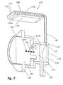
- the discharge device according to the Fig. 2 largely corresponds to the discharge of the Fig. 1 , With regard to the pumping device 110, there are no differences, so that the already to the embodiment of Fig. 1 said also applies for this. Notwithstanding the embodiment of the Fig. 1 instead, no outlet valve is provided, but instead a nebuliser 170 connected to the pressure chamber 116 via a conduit 140.
- This nebulizer consists of a housing 172 closed on its upper side by a perforated plate 174, the orifice plate 174 and the housing 172 coexisting with an outlet chamber 176 include.
- a vibration piezo 178 is provided on a vibration wall section 172a, which can generate a vibration of the vibration wall section 172a by high-frequency vibration.
- vibrations in the vibration wall portion 172a result in a high frequency volume change of the discharge chamber 176, through which the medium enclosed in the chamber 176 is forced through outlet openings 180 of the perforated plate 174 and escapes in the form of a mist.
- the presentation of the Fig. 2 is not to scale.
- the nebulizer 170 is shown significantly enlarged in relation to the pumping device 110.
- the volume of the pressure chamber 116 is therefore in reality many times greater than the volume of the outlet chamber 176, so that a long-lasting discharge process can be fed by the medium in the pressure chamber 116.
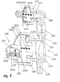
- Fig. 3 corresponds to the structure of the embodiment of the Fig. 1 with the exception that the piston 214 is not kraftbeaufschlagbar by a Spulenaktuator worn, but by a Piezoaktuator worn 230.
- This Piezoaktuator issued 230 includes a piezo-stack 232, which is adapted to increase its extension in the direction 206 when a voltage is applied.
- This direction 206 includes a right angle with the direction of movement 202 of the piston 214.
- a converter 236 is provided, which consists of two wedge elements 236a, 236b.
- the wedge member 236b is provided at the movable end 232 a of the piezo-stack 232.
- the other wedge element 236a is plugged onto the side of the piston 214 facing away from the pressure chamber 216.
- the wedge surfaces form an angle of about 15 ° with the direction of movement 202. This causes a displacement of the movable end 232a of the piezo-stack 232 to result in a significantly larger displacement of the piston 214. A comparatively small movement of the piezo stack 232 can thus cause a significantly larger piston stroke.
- the illustrated design thus allows the force generated by the piezo stack 232 to be used to generate pressure in the pressure chamber 216. Since the converter 236 is designed such that a force application of the piston 214 is only possible in the direction 202a, a return spring 238 is additionally provided which pushes the piston 214 back to its starting position when the force generated by the piezo stack 232 is eliminated.
Applications Claiming Priority (1)
| Application Number | Priority Date | Filing Date | Title |
|---|---|---|---|
| US12/284,244 US20100072302A1 (en) | 2008-09-19 | 2008-09-19 | Discharge device |
Publications (2)
| Publication Number | Publication Date |
|---|---|
| EP2165769A2 true EP2165769A2 (fr) | 2010-03-24 |
| EP2165769A3 EP2165769A3 (fr) | 2011-11-02 |
Family
ID=41268221
Family Applications (1)
| Application Number | Title | Priority Date | Filing Date |
|---|---|---|---|
| EP09011454A Withdrawn EP2165769A3 (fr) | 2008-09-19 | 2009-09-08 | Dispositif de distribution |
Country Status (4)
| Country | Link |
|---|---|
| US (1) | US20100072302A1 (fr) |
| EP (1) | EP2165769A3 (fr) |
| JP (1) | JP2010069480A (fr) |
| DE (1) | DE102008060813B3 (fr) |
Families Citing this family (9)
| Publication number | Priority date | Publication date | Assignee | Title |
|---|---|---|---|---|
| US20100076388A1 (en) * | 2008-09-19 | 2010-03-25 | Miro Cater | Discharge device for pharmaceutical media |
| CN107106325B (zh) | 2015-01-12 | 2021-05-25 | 科达莱昂治疗公司 | 微滴递送设备和方法 |
| JP5994881B2 (ja) * | 2015-02-20 | 2016-09-21 | セイコーエプソン株式会社 | 流体噴射装置 |
| CN109674576B (zh) * | 2017-10-19 | 2024-02-27 | 深圳市启明医药科技有限公司 | 流体供应单元及微液滴喷射驱动装置、发生装置 |
| US20190314195A1 (en) * | 2018-04-12 | 2019-10-17 | Kedalion Therapeutics, Inc. | Topical Ocular Delivery Methods and Devices for Use in the Same |
| US20210137732A1 (en) * | 2019-03-06 | 2021-05-13 | Kedalion Therapeutics, Inc. | Vented Multi-dose Ocular Fluid Delivery System |
| US11679028B2 (en) * | 2019-03-06 | 2023-06-20 | Novartis Ag | Multi-dose ocular fluid delivery system |
| IL297215A (en) | 2020-04-17 | 2022-12-01 | Kedallon Therapeutics Inc | A hydrodynamically activated preservative free distribution system |
| US11938057B2 (en) | 2020-04-17 | 2024-03-26 | Bausch + Lomb Ireland Limited | Hydrodynamically actuated preservative free dispensing system |
Citations (6)
| Publication number | Priority date | Publication date | Assignee | Title |
|---|---|---|---|---|
| NL6407541A (fr) * | 1964-07-02 | 1966-01-03 | ||
| DE6923398U (de) * | 1969-06-12 | 1969-12-04 | Karl-Heinz Schrupstock | Zerstaeuber fuer fluessige stoffe |
| EP0116869A2 (fr) * | 1983-02-18 | 1984-08-29 | J. Wagner GmbH | Moteur à armature oscillante pour l'entraînement des dispositifs électriques |
| EP0213234A1 (fr) * | 1985-09-06 | 1987-03-11 | Wagner International Ag | Pistolet de pulvérisation sans air |
| DE3838558A1 (de) * | 1988-11-14 | 1990-05-17 | Peter Kwasny | Einweg-airless-spruehdose mit elektrischem antrieb |
| EP1932597A2 (fr) * | 2006-12-15 | 2008-06-18 | Ing. Erich Pfeiffer GmbH | Dispositif de dosage |
Family Cites Families (4)
| Publication number | Priority date | Publication date | Assignee | Title |
|---|---|---|---|---|
| US3116879A (en) * | 1962-01-30 | 1964-01-07 | Charles S Tanner Company | Spray head for spray gun |
| US4261689A (en) * | 1979-02-08 | 1981-04-14 | Man Design Co., Ltd. | Electro-magnetic fluid pump |
| US6386842B1 (en) * | 2001-01-26 | 2002-05-14 | Delphi Technologies, Inc. | Low cost, single stroke, electromagnetic pre-charge pump for controlled brake systems |
| DE10122065B4 (de) * | 2001-05-07 | 2007-10-04 | Pari GmbH Spezialisten für effektive Inhalation | Vorrichtung zur Erzeugung von Flüssigkeitströpfchen mit einer in Schwingungen versetzten Membran |
-
2008
- 2008-09-19 US US12/284,244 patent/US20100072302A1/en not_active Abandoned
- 2008-12-01 DE DE102008060813A patent/DE102008060813B3/de not_active Expired - Fee Related
-
2009
- 2009-09-08 EP EP09011454A patent/EP2165769A3/fr not_active Withdrawn
- 2009-09-10 JP JP2009208928A patent/JP2010069480A/ja active Pending
Patent Citations (6)
| Publication number | Priority date | Publication date | Assignee | Title |
|---|---|---|---|---|
| NL6407541A (fr) * | 1964-07-02 | 1966-01-03 | ||
| DE6923398U (de) * | 1969-06-12 | 1969-12-04 | Karl-Heinz Schrupstock | Zerstaeuber fuer fluessige stoffe |
| EP0116869A2 (fr) * | 1983-02-18 | 1984-08-29 | J. Wagner GmbH | Moteur à armature oscillante pour l'entraînement des dispositifs électriques |
| EP0213234A1 (fr) * | 1985-09-06 | 1987-03-11 | Wagner International Ag | Pistolet de pulvérisation sans air |
| DE3838558A1 (de) * | 1988-11-14 | 1990-05-17 | Peter Kwasny | Einweg-airless-spruehdose mit elektrischem antrieb |
| EP1932597A2 (fr) * | 2006-12-15 | 2008-06-18 | Ing. Erich Pfeiffer GmbH | Dispositif de dosage |
Also Published As
| Publication number | Publication date |
|---|---|
| US20100072302A1 (en) | 2010-03-25 |
| DE102008060813B3 (de) | 2010-02-11 |
| EP2165769A3 (fr) | 2011-11-02 |
| JP2010069480A (ja) | 2010-04-02 |
Similar Documents
| Publication | Publication Date | Title |
|---|---|---|
| EP2165770B1 (fr) | Dispositif de sortie | |
| DE102008060813B3 (de) | Austragvorrichtung | |
| EP1654068B1 (fr) | Dispositif de microdosage et procede de delivrance dosee de liquides | |
| EP0556566B1 (fr) | Appareil pour la distribution dosée de réactifs | |
| EP2734371B3 (fr) | Tête d'impression pour imprimante à jet d'encre | |
| DE4241073C1 (de) | Apparat für die dosierte Abgabe von einem Fluid, insbesondere von einem Schmiermittelfluid | |
| WO2003099442A1 (fr) | Procede et dispositif pour doser de petits volumes de liquides | |
| DE102012209314A1 (de) | Vorrichtung und Verfahren zur Abgabe oder Aufnahme eines Flüssigkeitsvolumens | |
| EP3462140B1 (fr) | Procédé et dispositif de dosage pour une distribution de fluide dosée | |
| DE102018130159A1 (de) | Reinigungseinheit | |
| DE102007002402B4 (de) | Gaseinblasvorrichtung für einen Verbrennungsmotor | |
| DE102008046562A1 (de) | Hydraulischer Linearantrieb | |
| EP3687699B1 (fr) | Applicateur muni d'une membrane étanche | |
| EP1384901B1 (fr) | Procédé de régulation pour la mise en pression au moyen de multiplicateurs de pression, spécialement pour tester la compression de tubes | |
| WO1996035876A1 (fr) | Dispositif de refoulement | |
| WO2020120176A2 (fr) | Système de dosage et procédé pour commander un système de dosage | |
| EP2010784B1 (fr) | Élément de pompage et pompe comportant un tel élément de pompage | |
| DE102018203779A1 (de) | Magnetaktor für eine Vorrichtung zur Dosierung von flüssigen Medien und/oder Werkstoffen, Vorrichtung und Verfahren zur Dosierung von flüssigen Medien und/oder Werkstoffen | |
| EP2945754B1 (fr) | Dispositif de dosage | |
| EP2086689B1 (fr) | Unité soupape destinée à interrompre ou à libérer l'écoulement d'un fluide le long d'un conduit creux, son utilisation dans un système de dosage permettant un débit dosé dudit fluide, et procédé de mise en oeuvre associé | |
| DE19911456A1 (de) | Mehrkanal-Tropfengenerator | |
| EP2446910A1 (fr) | Pompe et procédé de transport d'un fluide et corps creux pour une pompe | |
| DE102005002768A1 (de) | Kraftstoffeinspritzvorrichtung für einen Verbrennungsmotor | |
| WO2011060855A2 (fr) | Actionneur électrohydraulique | |
| DE102008036976A1 (de) | Pumpeinrichtung sowie Verfahren zum Betreiben einer Pumpeinrichtung |
Legal Events
| Date | Code | Title | Description |
|---|---|---|---|
| PUAI | Public reference made under article 153(3) epc to a published international application that has entered the european phase |
Free format text: ORIGINAL CODE: 0009012 |
|
| AK | Designated contracting states |
Kind code of ref document: A2 Designated state(s): AT BE BG CH CY CZ DE DK EE ES FI FR GB GR HR HU IE IS IT LI LT LU LV MC MK MT NL NO PL PT RO SE SI SK SM TR |
|
| AX | Request for extension of the european patent |
Extension state: AL BA RS |
|
| PUAL | Search report despatched |
Free format text: ORIGINAL CODE: 0009013 |
|
| AK | Designated contracting states |
Kind code of ref document: A3 Designated state(s): AT BE BG CH CY CZ DE DK EE ES FI FR GB GR HR HU IE IS IT LI LT LU LV MC MK MT NL NO PL PT RO SE SI SK SM TR |
|
| AX | Request for extension of the european patent |
Extension state: AL BA RS |
|
| RIC1 | Information provided on ipc code assigned before grant |
Ipc: A61M 11/00 20060101ALI20110926BHEP Ipc: B05B 9/04 20060101ALI20110926BHEP Ipc: B05B 17/06 20060101ALI20110926BHEP Ipc: B05B 9/08 20060101ALI20110926BHEP Ipc: B05B 1/30 20060101AFI20110926BHEP |
|
| STAA | Information on the status of an ep patent application or granted ep patent |
Free format text: STATUS: THE APPLICATION IS DEEMED TO BE WITHDRAWN |
|
| 18D | Application deemed to be withdrawn |
Effective date: 20120503 |