EP2164709B1 - Light to heat conversion layer incorporating modified pigment - Google Patents
Light to heat conversion layer incorporating modified pigment Download PDFInfo
- Publication number
- EP2164709B1 EP2164709B1 EP08779788A EP08779788A EP2164709B1 EP 2164709 B1 EP2164709 B1 EP 2164709B1 EP 08779788 A EP08779788 A EP 08779788A EP 08779788 A EP08779788 A EP 08779788A EP 2164709 B1 EP2164709 B1 EP 2164709B1
- Authority
- EP
- European Patent Office
- Prior art keywords
- pigment
- layer
- modified pigment
- group
- modified
- Prior art date
- Legal status (The legal status is an assumption and is not a legal conclusion. Google has not performed a legal analysis and makes no representation as to the accuracy of the status listed.)
- Active
Links
- 239000000049 pigment Substances 0.000 title claims abstract description 231
- 238000006243 chemical reaction Methods 0.000 title claims description 10
- 238000012546 transfer Methods 0.000 claims abstract description 96
- 239000000203 mixture Substances 0.000 claims description 81
- 239000000463 material Substances 0.000 claims description 68
- 239000002270 dispersing agent Substances 0.000 claims description 52
- 239000006229 carbon black Substances 0.000 claims description 50
- 239000002904 solvent Substances 0.000 claims description 48
- 238000000034 method Methods 0.000 claims description 47
- 229920000642 polymer Polymers 0.000 claims description 39
- 239000000758 substrate Substances 0.000 claims description 28
- 239000011159 matrix material Substances 0.000 claims description 24
- 125000000962 organic group Chemical group 0.000 claims description 23
- 238000000576 coating method Methods 0.000 claims description 20
- 239000011248 coating agent Substances 0.000 claims description 17
- 229920005989 resin Polymers 0.000 claims description 17
- 239000011347 resin Substances 0.000 claims description 17
- 230000003746 surface roughness Effects 0.000 claims description 17
- 238000004519 manufacturing process Methods 0.000 claims description 14
- 150000003839 salts Chemical class 0.000 claims description 11
- 239000000178 monomer Substances 0.000 claims description 10
- 230000003287 optical effect Effects 0.000 claims description 9
- 239000013066 combination product Substances 0.000 claims description 8
- 229940127555 combination product Drugs 0.000 claims description 8
- 125000000542 sulfonic acid group Chemical group 0.000 claims description 8
- 239000004973 liquid crystal related substance Substances 0.000 claims description 7
- 239000011358 absorbing material Substances 0.000 claims description 6
- 239000011149 active material Substances 0.000 claims description 6
- 239000002243 precursor Substances 0.000 claims description 6
- 239000012141 concentrate Substances 0.000 claims description 5
- 238000004528 spin coating Methods 0.000 claims description 5
- 229910006069 SO3H Inorganic materials 0.000 claims description 4
- 125000003178 carboxy group Chemical group [H]OC(*)=O 0.000 claims description 4
- 125000002843 carboxylic acid group Chemical group 0.000 claims description 4
- 230000001678 irradiating effect Effects 0.000 claims description 4
- 238000003618 dip coating Methods 0.000 claims description 3
- 238000007646 gravure printing Methods 0.000 claims description 3
- 125000002887 hydroxy group Chemical group [H]O* 0.000 claims description 3
- 239000002318 adhesion promoter Substances 0.000 claims description 2
- 239000003999 initiator Substances 0.000 claims description 2
- 230000005855 radiation Effects 0.000 abstract description 11
- 239000010410 layer Substances 0.000 description 162
- 239000006185 dispersion Substances 0.000 description 99
- 235000019241 carbon black Nutrition 0.000 description 48
- OKTJSMMVPCPJKN-UHFFFAOYSA-N Carbon Chemical class [C] OKTJSMMVPCPJKN-UHFFFAOYSA-N 0.000 description 38
- 238000011068 loading method Methods 0.000 description 36
- ZWEHNKRNPOVVGH-UHFFFAOYSA-N 2-Butanone Chemical compound CCC(C)=O ZWEHNKRNPOVVGH-UHFFFAOYSA-N 0.000 description 24
- 239000002245 particle Substances 0.000 description 23
- 239000011521 glass Substances 0.000 description 19
- 239000011324 bead Substances 0.000 description 18
- -1 nitric acid Chemical class 0.000 description 17
- OKKJLVBELUTLKV-UHFFFAOYSA-N Methanol Chemical compound OC OKKJLVBELUTLKV-UHFFFAOYSA-N 0.000 description 15
- 239000011229 interlayer Substances 0.000 description 14
- LYCAIKOWRPUZTN-UHFFFAOYSA-N Ethylene glycol Chemical compound OCCO LYCAIKOWRPUZTN-UHFFFAOYSA-N 0.000 description 12
- 125000003010 ionic group Chemical group 0.000 description 12
- 125000000524 functional group Chemical group 0.000 description 11
- 238000002156 mixing Methods 0.000 description 11
- XLYOFNOQVPJJNP-UHFFFAOYSA-N water Substances O XLYOFNOQVPJJNP-UHFFFAOYSA-N 0.000 description 10
- 241000721047 Danaus plexippus Species 0.000 description 9
- ALYNCZNDIQEVRV-UHFFFAOYSA-N 4-aminobenzoic acid Chemical compound NC1=CC=C(C(O)=O)C=C1 ALYNCZNDIQEVRV-UHFFFAOYSA-N 0.000 description 8
- 150000001721 carbon Chemical class 0.000 description 8
- 239000003973 paint Substances 0.000 description 8
- 239000007787 solid Substances 0.000 description 8
- HVBSAKJJOYLTQU-UHFFFAOYSA-N 4-aminobenzenesulfonic acid Chemical group NC1=CC=C(S(O)(=O)=O)C=C1 HVBSAKJJOYLTQU-UHFFFAOYSA-N 0.000 description 7
- 230000032683 aging Effects 0.000 description 7
- 125000000129 anionic group Chemical group 0.000 description 7
- 238000002360 preparation method Methods 0.000 description 7
- 238000007639 printing Methods 0.000 description 7
- 230000035882 stress Effects 0.000 description 7
- 239000002253 acid Substances 0.000 description 6
- 125000000217 alkyl group Chemical group 0.000 description 6
- 238000001035 drying Methods 0.000 description 6
- 238000003384 imaging method Methods 0.000 description 6
- 239000011236 particulate material Substances 0.000 description 6
- 230000008569 process Effects 0.000 description 6
- 239000000047 product Substances 0.000 description 6
- IJGRMHOSHXDMSA-UHFFFAOYSA-N Atomic nitrogen Chemical compound N#N IJGRMHOSHXDMSA-UHFFFAOYSA-N 0.000 description 5
- 125000003118 aryl group Chemical group 0.000 description 5
- 125000002091 cationic group Chemical group 0.000 description 5
- 230000008859 change Effects 0.000 description 5
- 125000003636 chemical group Chemical group 0.000 description 5
- XCJYREBRNVKWGJ-UHFFFAOYSA-N copper(II) phthalocyanine Chemical class [Cu+2].C12=CC=CC=C2C(N=C2[N-]C(C3=CC=CC=C32)=N2)=NC1=NC([C]1C=CC=CC1=1)=NC=1N=C1[C]3C=CC=CC3=C2[N-]1 XCJYREBRNVKWGJ-UHFFFAOYSA-N 0.000 description 5
- 239000012954 diazonium Substances 0.000 description 5
- 239000010408 film Substances 0.000 description 5
- 229910052739 hydrogen Inorganic materials 0.000 description 5
- 239000001257 hydrogen Substances 0.000 description 5
- 230000006872 improvement Effects 0.000 description 5
- 239000007800 oxidant agent Substances 0.000 description 5
- 150000003141 primary amines Chemical group 0.000 description 5
- 239000004593 Epoxy Substances 0.000 description 4
- 239000000654 additive Substances 0.000 description 4
- 238000000149 argon plasma sintering Methods 0.000 description 4
- IISBACLAFKSPIT-UHFFFAOYSA-N bisphenol A Chemical compound C=1C=C(O)C=CC=1C(C)(C)C1=CC=C(O)C=C1 IISBACLAFKSPIT-UHFFFAOYSA-N 0.000 description 4
- 230000000903 blocking effect Effects 0.000 description 4
- 229910052799 carbon Inorganic materials 0.000 description 4
- 238000005342 ion exchange Methods 0.000 description 4
- 235000019592 roughness Nutrition 0.000 description 4
- 125000001424 substituent group Chemical group 0.000 description 4
- QTBSBXVTEAMEQO-UHFFFAOYSA-M Acetate Chemical compound CC([O-])=O QTBSBXVTEAMEQO-UHFFFAOYSA-M 0.000 description 3
- RTZKZFJDLAIYFH-UHFFFAOYSA-N Diethyl ether Chemical compound CCOCC RTZKZFJDLAIYFH-UHFFFAOYSA-N 0.000 description 3
- XEKOWRVHYACXOJ-UHFFFAOYSA-N Ethyl acetate Chemical compound CCOC(C)=O XEKOWRVHYACXOJ-UHFFFAOYSA-N 0.000 description 3
- ZMXDDKWLCZADIW-UHFFFAOYSA-N N,N-Dimethylformamide Chemical compound CN(C)C=O ZMXDDKWLCZADIW-UHFFFAOYSA-N 0.000 description 3
- 239000004721 Polyphenylene oxide Substances 0.000 description 3
- 238000010521 absorption reaction Methods 0.000 description 3
- 150000001450 anions Chemical class 0.000 description 3
- 239000003125 aqueous solvent Substances 0.000 description 3
- 230000015572 biosynthetic process Effects 0.000 description 3
- 239000008199 coating composition Substances 0.000 description 3
- 239000006184 cosolvent Substances 0.000 description 3
- 230000007547 defect Effects 0.000 description 3
- 238000000151 deposition Methods 0.000 description 3
- IJGRMHOSHXDMSA-UHFFFAOYSA-O diazynium Chemical compound [NH+]#N IJGRMHOSHXDMSA-UHFFFAOYSA-O 0.000 description 3
- DOIRQSBPFJWKBE-UHFFFAOYSA-N dibutyl phthalate Chemical compound CCCCOC(=O)C1=CC=CC=C1C(=O)OCCCC DOIRQSBPFJWKBE-UHFFFAOYSA-N 0.000 description 3
- MTHSVFCYNBDYFN-UHFFFAOYSA-N diethylene glycol Chemical compound OCCOCCO MTHSVFCYNBDYFN-UHFFFAOYSA-N 0.000 description 3
- 229940028356 diethylene glycol monobutyl ether Drugs 0.000 description 3
- 238000001914 filtration Methods 0.000 description 3
- 238000010438 heat treatment Methods 0.000 description 3
- 125000004435 hydrogen atom Chemical group [H]* 0.000 description 3
- 229910010272 inorganic material Inorganic materials 0.000 description 3
- 239000011147 inorganic material Substances 0.000 description 3
- 230000003993 interaction Effects 0.000 description 3
- 238000002032 lab-on-a-chip Methods 0.000 description 3
- 239000000693 micelle Substances 0.000 description 3
- JCGNDDUYTRNOFT-UHFFFAOYSA-N oxolane-2,4-dione Chemical compound O=C1COC(=O)C1 JCGNDDUYTRNOFT-UHFFFAOYSA-N 0.000 description 3
- 238000000059 patterning Methods 0.000 description 3
- 239000012071 phase Substances 0.000 description 3
- IEQIEDJGQAUEQZ-UHFFFAOYSA-N phthalocyanine Chemical compound N1C(N=C2C3=CC=CC=C3C(N=C3C4=CC=CC=C4C(=N4)N3)=N2)=C(C=CC=C2)C2=C1N=C1C2=CC=CC=C2C4=N1 IEQIEDJGQAUEQZ-UHFFFAOYSA-N 0.000 description 3
- 229920000728 polyester Polymers 0.000 description 3
- 229920000570 polyether Polymers 0.000 description 3
- LLHKCFNBLRBOGN-UHFFFAOYSA-N propylene glycol methyl ether acetate Chemical compound COCC(C)OC(C)=O LLHKCFNBLRBOGN-UHFFFAOYSA-N 0.000 description 3
- 238000001179 sorption measurement Methods 0.000 description 3
- 241000894007 species Species 0.000 description 3
- 238000003860 storage Methods 0.000 description 3
- 239000000126 substance Substances 0.000 description 3
- 229950000244 sulfanilic acid Drugs 0.000 description 3
- 239000004094 surface-active agent Substances 0.000 description 3
- 238000000108 ultra-filtration Methods 0.000 description 3
- LJRSZGKUUZPHEB-UHFFFAOYSA-N 2-[2-(2-prop-2-enoyloxypropoxy)propoxy]propyl prop-2-enoate Chemical compound C=CC(=O)OC(C)COC(C)COC(C)COC(=O)C=C LJRSZGKUUZPHEB-UHFFFAOYSA-N 0.000 description 2
- CSCPPACGZOOCGX-UHFFFAOYSA-N Acetone Chemical compound CC(C)=O CSCPPACGZOOCGX-UHFFFAOYSA-N 0.000 description 2
- BHPQYMZQTOCNFJ-UHFFFAOYSA-N Calcium cation Chemical compound [Ca+2] BHPQYMZQTOCNFJ-UHFFFAOYSA-N 0.000 description 2
- IAZDPXIOMUYVGZ-UHFFFAOYSA-N Dimethylsulphoxide Chemical compound CS(C)=O IAZDPXIOMUYVGZ-UHFFFAOYSA-N 0.000 description 2
- MHAJPDPJQMAIIY-UHFFFAOYSA-N Hydrogen peroxide Chemical compound OO MHAJPDPJQMAIIY-UHFFFAOYSA-N 0.000 description 2
- XEEYBQQBJWHFJM-UHFFFAOYSA-N Iron Chemical compound [Fe] XEEYBQQBJWHFJM-UHFFFAOYSA-N 0.000 description 2
- 229920005692 JONCRYL® Polymers 0.000 description 2
- 229910002651 NO3 Inorganic materials 0.000 description 2
- CBENFWSGALASAD-UHFFFAOYSA-N Ozone Chemical compound [O-][O+]=O CBENFWSGALASAD-UHFFFAOYSA-N 0.000 description 2
- 239000004952 Polyamide Substances 0.000 description 2
- WYURNTSHIVDZCO-UHFFFAOYSA-N Tetrahydrofuran Chemical compound C1CCOC1 WYURNTSHIVDZCO-UHFFFAOYSA-N 0.000 description 2
- XLOMVQKBTHCTTD-UHFFFAOYSA-N Zinc monoxide Chemical compound [Zn]=O XLOMVQKBTHCTTD-UHFFFAOYSA-N 0.000 description 2
- HVVWZTWDBSEWIH-UHFFFAOYSA-N [2-(hydroxymethyl)-3-prop-2-enoyloxy-2-(prop-2-enoyloxymethyl)propyl] prop-2-enoate Chemical compound C=CC(=O)OCC(CO)(COC(=O)C=C)COC(=O)C=C HVVWZTWDBSEWIH-UHFFFAOYSA-N 0.000 description 2
- 230000002378 acidificating effect Effects 0.000 description 2
- 238000005054 agglomeration Methods 0.000 description 2
- 230000002776 aggregation Effects 0.000 description 2
- 150000001298 alcohols Chemical class 0.000 description 2
- 150000001412 amines Chemical class 0.000 description 2
- 125000003277 amino group Chemical group 0.000 description 2
- QGZKDVFQNNGYKY-UHFFFAOYSA-O ammonium group Chemical group [NH4+] QGZKDVFQNNGYKY-UHFFFAOYSA-O 0.000 description 2
- QVGXLLKOCUKJST-UHFFFAOYSA-N atomic oxygen Chemical compound [O] QVGXLLKOCUKJST-UHFFFAOYSA-N 0.000 description 2
- 230000008901 benefit Effects 0.000 description 2
- 229940106691 bisphenol a Drugs 0.000 description 2
- 239000006227 byproduct Substances 0.000 description 2
- 229910001424 calcium ion Inorganic materials 0.000 description 2
- 150000001732 carboxylic acid derivatives Chemical class 0.000 description 2
- 150000001768 cations Chemical class 0.000 description 2
- 238000005119 centrifugation Methods 0.000 description 2
- XMPZTFVPEKAKFH-UHFFFAOYSA-P ceric ammonium nitrate Chemical compound [NH4+].[NH4+].[Ce+4].[O-][N+]([O-])=O.[O-][N+]([O-])=O.[O-][N+]([O-])=O.[O-][N+]([O-])=O.[O-][N+]([O-])=O.[O-][N+]([O-])=O XMPZTFVPEKAKFH-UHFFFAOYSA-P 0.000 description 2
- 230000000052 comparative effect Effects 0.000 description 2
- 150000001875 compounds Chemical class 0.000 description 2
- JHIVVAPYMSGYDF-UHFFFAOYSA-N cyclohexanone Chemical compound O=C1CCCCC1 JHIVVAPYMSGYDF-UHFFFAOYSA-N 0.000 description 2
- 230000003247 decreasing effect Effects 0.000 description 2
- 238000011026 diafiltration Methods 0.000 description 2
- 150000001989 diazonium salts Chemical class 0.000 description 2
- XXJWXESWEXIICW-UHFFFAOYSA-N diethylene glycol monoethyl ether Chemical compound CCOCCOCCO XXJWXESWEXIICW-UHFFFAOYSA-N 0.000 description 2
- 238000009792 diffusion process Methods 0.000 description 2
- 238000002296 dynamic light scattering Methods 0.000 description 2
- 238000001704 evaporation Methods 0.000 description 2
- 230000008020 evaporation Effects 0.000 description 2
- 238000005189 flocculation Methods 0.000 description 2
- 230000016615 flocculation Effects 0.000 description 2
- 239000012535 impurity Substances 0.000 description 2
- 239000000976 ink Substances 0.000 description 2
- 150000002500 ions Chemical class 0.000 description 2
- 239000007788 liquid Substances 0.000 description 2
- 229910044991 metal oxide Inorganic materials 0.000 description 2
- 150000004706 metal oxides Chemical class 0.000 description 2
- 229910052757 nitrogen Inorganic materials 0.000 description 2
- 229920003986 novolac Polymers 0.000 description 2
- 239000001301 oxygen Substances 0.000 description 2
- 229910052760 oxygen Inorganic materials 0.000 description 2
- 239000005022 packaging material Substances 0.000 description 2
- 229920000233 poly(alkylene oxides) Polymers 0.000 description 2
- 229920000058 polyacrylate Polymers 0.000 description 2
- 229920002647 polyamide Polymers 0.000 description 2
- 229920005862 polyol Polymers 0.000 description 2
- 150000003077 polyols Chemical class 0.000 description 2
- 125000001453 quaternary ammonium group Chemical group 0.000 description 2
- 239000001054 red pigment Substances 0.000 description 2
- 230000009467 reduction Effects 0.000 description 2
- 238000000518 rheometry Methods 0.000 description 2
- LPXPTNMVRIOKMN-UHFFFAOYSA-M sodium nitrite Chemical compound [Na+].[O-]N=O LPXPTNMVRIOKMN-UHFFFAOYSA-M 0.000 description 2
- 239000000243 solution Substances 0.000 description 2
- 238000001228 spectrum Methods 0.000 description 2
- 238000012360 testing method Methods 0.000 description 2
- 229920001169 thermoplastic Polymers 0.000 description 2
- 239000010409 thin film Substances 0.000 description 2
- ARXJGSRGQADJSQ-UHFFFAOYSA-N 1-methoxypropan-2-ol Chemical compound COCC(C)O ARXJGSRGQADJSQ-UHFFFAOYSA-N 0.000 description 1
- QQZOPKMRPOGIEB-UHFFFAOYSA-N 2-Oxohexane Chemical compound CCCCC(C)=O QQZOPKMRPOGIEB-UHFFFAOYSA-N 0.000 description 1
- POAOYUHQDCAZBD-UHFFFAOYSA-N 2-butoxyethanol Chemical compound CCCCOCCO POAOYUHQDCAZBD-UHFFFAOYSA-N 0.000 description 1
- NQBXSWAWVZHKBZ-UHFFFAOYSA-N 2-butoxyethyl acetate Chemical compound CCCCOCCOC(C)=O NQBXSWAWVZHKBZ-UHFFFAOYSA-N 0.000 description 1
- ZNQVEEAIQZEUHB-UHFFFAOYSA-N 2-ethoxyethanol Chemical compound CCOCCO ZNQVEEAIQZEUHB-UHFFFAOYSA-N 0.000 description 1
- SVONRAPFKPVNKG-UHFFFAOYSA-N 2-ethoxyethyl acetate Chemical compound CCOCCOC(C)=O SVONRAPFKPVNKG-UHFFFAOYSA-N 0.000 description 1
- XQGDNRFLRLSUFQ-UHFFFAOYSA-N 2H-pyranthren-1-one Chemical class C1=C(C2=C3C4=C56)C=CC3=CC5=C3C=CC=CC3=CC6=CC=C4C=C2C2=C1C(=O)CC=C2 XQGDNRFLRLSUFQ-UHFFFAOYSA-N 0.000 description 1
- 229920000178 Acrylic resin Polymers 0.000 description 1
- 239000004925 Acrylic resin Substances 0.000 description 1
- 102100030356 Arginase-2, mitochondrial Human genes 0.000 description 1
- LSNNMFCWUKXFEE-UHFFFAOYSA-M Bisulfite Chemical compound OS([O-])=O LSNNMFCWUKXFEE-UHFFFAOYSA-M 0.000 description 1
- DKPFZGUDAPQIHT-UHFFFAOYSA-N Butyl acetate Natural products CCCCOC(C)=O DKPFZGUDAPQIHT-UHFFFAOYSA-N 0.000 description 1
- 229920000049 Carbon (fiber) Polymers 0.000 description 1
- YZCKVEUIGOORGS-OUBTZVSYSA-N Deuterium Chemical compound [2H] YZCKVEUIGOORGS-OUBTZVSYSA-N 0.000 description 1
- MYMOFIZGZYHOMD-UHFFFAOYSA-N Dioxygen Chemical compound O=O MYMOFIZGZYHOMD-UHFFFAOYSA-N 0.000 description 1
- 206010073306 Exposure to radiation Diseases 0.000 description 1
- GYHNNYVSQQEPJS-UHFFFAOYSA-N Gallium Chemical compound [Ga] GYHNNYVSQQEPJS-UHFFFAOYSA-N 0.000 description 1
- 101000792835 Homo sapiens Arginase-2, mitochondrial Proteins 0.000 description 1
- UFHFLCQGNIYNRP-UHFFFAOYSA-N Hydrogen Chemical compound [H][H] UFHFLCQGNIYNRP-UHFFFAOYSA-N 0.000 description 1
- DGAQECJNVWCQMB-PUAWFVPOSA-M Ilexoside XXIX Chemical compound C[C@@H]1CC[C@@]2(CC[C@@]3(C(=CC[C@H]4[C@]3(CC[C@@H]5[C@@]4(CC[C@@H](C5(C)C)OS(=O)(=O)[O-])C)C)[C@@H]2[C@]1(C)O)C)C(=O)O[C@H]6[C@@H]([C@H]([C@@H]([C@H](O6)CO)O)O)O.[Na+] DGAQECJNVWCQMB-PUAWFVPOSA-M 0.000 description 1
- GRYLNZFGIOXLOG-UHFFFAOYSA-N Nitric acid Chemical compound O[N+]([O-])=O GRYLNZFGIOXLOG-UHFFFAOYSA-N 0.000 description 1
- IOVCWXUNBOPUCH-UHFFFAOYSA-M Nitrite anion Chemical compound [O-]N=O IOVCWXUNBOPUCH-UHFFFAOYSA-M 0.000 description 1
- 229920002292 Nylon 6 Polymers 0.000 description 1
- 229910018828 PO3H2 Inorganic materials 0.000 description 1
- ABLZXFCXXLZCGV-UHFFFAOYSA-N Phosphorous acid Chemical compound OP(O)=O ABLZXFCXXLZCGV-UHFFFAOYSA-N 0.000 description 1
- 229920003171 Poly (ethylene oxide) Polymers 0.000 description 1
- 239000004698 Polyethylene Substances 0.000 description 1
- 239000004642 Polyimide Substances 0.000 description 1
- 229920002396 Polyurea Polymers 0.000 description 1
- ZLMJMSJWJFRBEC-UHFFFAOYSA-N Potassium Chemical compound [K] ZLMJMSJWJFRBEC-UHFFFAOYSA-N 0.000 description 1
- 239000005708 Sodium hypochlorite Substances 0.000 description 1
- WGLPBDUCMAPZCE-UHFFFAOYSA-N Trioxochromium Chemical compound O=[Cr](=O)=O WGLPBDUCMAPZCE-UHFFFAOYSA-N 0.000 description 1
- 150000001242 acetic acid derivatives Chemical class 0.000 description 1
- 150000007513 acids Chemical class 0.000 description 1
- 150000001252 acrylic acid derivatives Chemical class 0.000 description 1
- 230000002411 adverse Effects 0.000 description 1
- 238000013019 agitation Methods 0.000 description 1
- 150000001336 alkenes Chemical group 0.000 description 1
- 125000003282 alkyl amino group Chemical group 0.000 description 1
- 125000005210 alkyl ammonium group Chemical group 0.000 description 1
- 229910052782 aluminium Inorganic materials 0.000 description 1
- XAGFODPZIPBFFR-UHFFFAOYSA-N aluminium Chemical compound [Al] XAGFODPZIPBFFR-UHFFFAOYSA-N 0.000 description 1
- 150000001408 amides Chemical class 0.000 description 1
- 238000005576 amination reaction Methods 0.000 description 1
- ROOXNKNUYICQNP-UHFFFAOYSA-N ammonium peroxydisulfate Substances [NH4+].[NH4+].[O-]S(=O)(=O)OOS([O-])(=O)=O ROOXNKNUYICQNP-UHFFFAOYSA-N 0.000 description 1
- VAZSKTXWXKYQJF-UHFFFAOYSA-N ammonium persulfate Chemical compound [NH4+].[NH4+].[O-]S(=O)OOS([O-])=O VAZSKTXWXKYQJF-UHFFFAOYSA-N 0.000 description 1
- 229910001870 ammonium persulfate Inorganic materials 0.000 description 1
- 150000004056 anthraquinones Chemical class 0.000 description 1
- 239000007864 aqueous solution Substances 0.000 description 1
- 150000004982 aromatic amines Chemical class 0.000 description 1
- IRERQBUNZFJFGC-UHFFFAOYSA-L azure blue Chemical compound [Na+].[Na+].[Na+].[Na+].[Na+].[Na+].[Na+].[Na+].[Al+3].[Al+3].[Al+3].[Al+3].[Al+3].[Al+3].[S-]S[S-].[O-][Si]([O-])([O-])[O-].[O-][Si]([O-])([O-])[O-].[O-][Si]([O-])([O-])[O-].[O-][Si]([O-])([O-])[O-].[O-][Si]([O-])([O-])[O-].[O-][Si]([O-])([O-])[O-] IRERQBUNZFJFGC-UHFFFAOYSA-L 0.000 description 1
- 238000000498 ball milling Methods 0.000 description 1
- 230000004888 barrier function Effects 0.000 description 1
- UJMDYLWCYJJYMO-UHFFFAOYSA-N benzene-1,2,3-tricarboxylic acid Chemical group OC(=O)C1=CC=CC(C(O)=O)=C1C(O)=O UJMDYLWCYJJYMO-UHFFFAOYSA-N 0.000 description 1
- SRSXLGNVWSONIS-UHFFFAOYSA-N benzenesulfonic acid Chemical group OS(=O)(=O)C1=CC=CC=C1 SRSXLGNVWSONIS-UHFFFAOYSA-N 0.000 description 1
- WPYMKLBDIGXBTP-UHFFFAOYSA-N benzoic acid Chemical group OC(=O)C1=CC=CC=C1 WPYMKLBDIGXBTP-UHFFFAOYSA-N 0.000 description 1
- 239000012620 biological material Substances 0.000 description 1
- 229910052797 bismuth Inorganic materials 0.000 description 1
- JCXGWMGPZLAOME-UHFFFAOYSA-N bismuth atom Chemical compound [Bi] JCXGWMGPZLAOME-UHFFFAOYSA-N 0.000 description 1
- 229920001400 block copolymer Polymers 0.000 description 1
- 239000001055 blue pigment Substances 0.000 description 1
- BTANRVKWQNVYAZ-UHFFFAOYSA-N butan-2-ol Chemical compound CCC(C)O BTANRVKWQNVYAZ-UHFFFAOYSA-N 0.000 description 1
- BTMVHUNTONAYDX-UHFFFAOYSA-N butyl propionate Chemical compound CCCCOC(=O)CC BTMVHUNTONAYDX-UHFFFAOYSA-N 0.000 description 1
- 239000001030 cadmium pigment Substances 0.000 description 1
- 239000004917 carbon fiber Substances 0.000 description 1
- 229910021393 carbon nanotube Inorganic materials 0.000 description 1
- 239000002041 carbon nanotube Substances 0.000 description 1
- 239000003575 carbonaceous material Substances 0.000 description 1
- 150000007942 carboxylates Chemical group 0.000 description 1
- 239000003153 chemical reaction reagent Substances 0.000 description 1
- 239000003795 chemical substances by application Substances 0.000 description 1
- 238000005229 chemical vapour deposition Methods 0.000 description 1
- 238000005660 chlorination reaction Methods 0.000 description 1
- ZCDOYSPFYFSLEW-UHFFFAOYSA-N chromate(2-) Chemical compound [O-][Cr]([O-])(=O)=O ZCDOYSPFYFSLEW-UHFFFAOYSA-N 0.000 description 1
- 229910000423 chromium oxide Inorganic materials 0.000 description 1
- UOUJSJZBMCDAEU-UHFFFAOYSA-N chromium(3+);oxygen(2-) Chemical class [O-2].[O-2].[O-2].[Cr+3].[Cr+3] UOUJSJZBMCDAEU-UHFFFAOYSA-N 0.000 description 1
- 239000002131 composite material Substances 0.000 description 1
- 238000006482 condensation reaction Methods 0.000 description 1
- 239000000356 contaminant Substances 0.000 description 1
- 238000012937 correction Methods 0.000 description 1
- 230000008878 coupling Effects 0.000 description 1
- 238000010168 coupling process Methods 0.000 description 1
- 238000005859 coupling reaction Methods 0.000 description 1
- 229920006037 cross link polymer Polymers 0.000 description 1
- 238000004925 denaturation Methods 0.000 description 1
- 230000036425 denaturation Effects 0.000 description 1
- 230000008021 deposition Effects 0.000 description 1
- 229910052805 deuterium Inorganic materials 0.000 description 1
- 150000004985 diamines Chemical group 0.000 description 1
- 229910003460 diamond Inorganic materials 0.000 description 1
- 239000010432 diamond Substances 0.000 description 1
- 125000000664 diazo group Chemical group [N-]=[N+]=[*] 0.000 description 1
- 229960002380 dibutyl phthalate Drugs 0.000 description 1
- 229960004132 diethyl ether Drugs 0.000 description 1
- 125000005442 diisocyanate group Chemical group 0.000 description 1
- 229910001873 dinitrogen Inorganic materials 0.000 description 1
- 150000002009 diols Chemical group 0.000 description 1
- 229910001882 dioxygen Inorganic materials 0.000 description 1
- 238000009826 distribution Methods 0.000 description 1
- 239000007772 electrode material Substances 0.000 description 1
- 238000000313 electron-beam-induced deposition Methods 0.000 description 1
- 150000002118 epoxides Chemical class 0.000 description 1
- 230000032050 esterification Effects 0.000 description 1
- 238000005886 esterification reaction Methods 0.000 description 1
- 150000002148 esters Chemical class 0.000 description 1
- 150000002170 ethers Chemical class 0.000 description 1
- 229940052303 ethers for general anesthesia Drugs 0.000 description 1
- 230000001747 exhibiting effect Effects 0.000 description 1
- 238000001125 extrusion Methods 0.000 description 1
- 238000007765 extrusion coating Methods 0.000 description 1
- 239000007888 film coating Substances 0.000 description 1
- 238000009501 film coating Methods 0.000 description 1
- 239000012467 final product Substances 0.000 description 1
- 239000012530 fluid Substances 0.000 description 1
- 229920002313 fluoropolymer Polymers 0.000 description 1
- 239000004811 fluoropolymer Substances 0.000 description 1
- 238000009472 formulation Methods 0.000 description 1
- 229910052733 gallium Inorganic materials 0.000 description 1
- 229910021397 glassy carbon Inorganic materials 0.000 description 1
- 150000002334 glycols Chemical class 0.000 description 1
- 229910002804 graphite Inorganic materials 0.000 description 1
- 239000010439 graphite Substances 0.000 description 1
- 238000007756 gravure coating Methods 0.000 description 1
- 235000021384 green leafy vegetables Nutrition 0.000 description 1
- RBTKNAXYKSUFRK-UHFFFAOYSA-N heliogen blue Chemical compound [Cu].[N-]1C2=C(C=CC=C3)C3=C1N=C([N-]1)C3=CC=CC=C3C1=NC([N-]1)=C(C=CC=C3)C3=C1N=C([N-]1)C3=CC=CC=C3C1=N2 RBTKNAXYKSUFRK-UHFFFAOYSA-N 0.000 description 1
- 125000000623 heterocyclic group Chemical group 0.000 description 1
- FUZZWVXGSFPDMH-UHFFFAOYSA-N hexanoic acid Chemical compound CCCCCC(O)=O FUZZWVXGSFPDMH-UHFFFAOYSA-N 0.000 description 1
- 229930195733 hydrocarbon Natural products 0.000 description 1
- 150000002430 hydrocarbons Chemical class 0.000 description 1
- 230000002209 hydrophobic effect Effects 0.000 description 1
- 238000011065 in-situ storage Methods 0.000 description 1
- 238000011534 incubation Methods 0.000 description 1
- 229910003437 indium oxide Inorganic materials 0.000 description 1
- PJXISJQVUVHSOJ-UHFFFAOYSA-N indium(iii) oxide Chemical compound [O-2].[O-2].[O-2].[In+3].[In+3] PJXISJQVUVHSOJ-UHFFFAOYSA-N 0.000 description 1
- AMGQUBHHOARCQH-UHFFFAOYSA-N indium;oxotin Chemical compound [In].[Sn]=O AMGQUBHHOARCQH-UHFFFAOYSA-N 0.000 description 1
- 238000007641 inkjet printing Methods 0.000 description 1
- 239000001023 inorganic pigment Substances 0.000 description 1
- 239000011810 insulating material Substances 0.000 description 1
- 229910000765 intermetallic Inorganic materials 0.000 description 1
- 229910052742 iron Inorganic materials 0.000 description 1
- 239000001034 iron oxide pigment Substances 0.000 description 1
- DCYOBGZUOMKFPA-UHFFFAOYSA-N iron(2+);iron(3+);octadecacyanide Chemical compound [Fe+2].[Fe+2].[Fe+2].[Fe+3].[Fe+3].[Fe+3].[Fe+3].N#[C-].N#[C-].N#[C-].N#[C-].N#[C-].N#[C-].N#[C-].N#[C-].N#[C-].N#[C-].N#[C-].N#[C-].N#[C-].N#[C-].N#[C-].N#[C-].N#[C-].N#[C-] DCYOBGZUOMKFPA-UHFFFAOYSA-N 0.000 description 1
- 238000010902 jet-milling Methods 0.000 description 1
- 150000002576 ketones Chemical class 0.000 description 1
- 150000003893 lactate salts Chemical class 0.000 description 1
- 239000007791 liquid phase Substances 0.000 description 1
- 238000001459 lithography Methods 0.000 description 1
- 239000002932 luster Substances 0.000 description 1
- 229920002521 macromolecule Polymers 0.000 description 1
- 238000005259 measurement Methods 0.000 description 1
- 238000002844 melting Methods 0.000 description 1
- 230000008018 melting Effects 0.000 description 1
- 239000012528 membrane Substances 0.000 description 1
- 150000002734 metacrylic acid derivatives Chemical class 0.000 description 1
- 229910052751 metal Inorganic materials 0.000 description 1
- 239000002184 metal Substances 0.000 description 1
- 229910052976 metal sulfide Inorganic materials 0.000 description 1
- 150000002739 metals Chemical class 0.000 description 1
- 125000005395 methacrylic acid group Chemical group 0.000 description 1
- 238000001471 micro-filtration Methods 0.000 description 1
- 238000003801 milling Methods 0.000 description 1
- 229910003455 mixed metal oxide Inorganic materials 0.000 description 1
- 230000004048 modification Effects 0.000 description 1
- 238000012986 modification Methods 0.000 description 1
- 238000002715 modification method Methods 0.000 description 1
- 238000006396 nitration reaction Methods 0.000 description 1
- 229910017604 nitric acid Inorganic materials 0.000 description 1
- 125000000449 nitro group Chemical group [O-][N+](*)=O 0.000 description 1
- 150000007523 nucleic acids Chemical class 0.000 description 1
- 102000039446 nucleic acids Human genes 0.000 description 1
- 108020004707 nucleic acids Proteins 0.000 description 1
- 239000001053 orange pigment Substances 0.000 description 1
- 239000011368 organic material Substances 0.000 description 1
- 125000002524 organometallic group Chemical group 0.000 description 1
- 239000012285 osmium tetroxide Substances 0.000 description 1
- 229910000489 osmium tetroxide Inorganic materials 0.000 description 1
- 230000003647 oxidation Effects 0.000 description 1
- 238000007254 oxidation reaction Methods 0.000 description 1
- 230000001590 oxidative effect Effects 0.000 description 1
- 150000002978 peroxides Chemical class 0.000 description 1
- JRKICGRDRMAZLK-UHFFFAOYSA-L persulfate group Chemical group S(=O)(=O)([O-])OOS(=O)(=O)[O-] JRKICGRDRMAZLK-UHFFFAOYSA-L 0.000 description 1
- 150000002979 perylenes Chemical class 0.000 description 1
- 238000005191 phase separation Methods 0.000 description 1
- 229920001568 phenolic resin Polymers 0.000 description 1
- 239000005011 phenolic resin Substances 0.000 description 1
- 125000005496 phosphonium group Chemical group 0.000 description 1
- XNGIFLGASWRNHJ-UHFFFAOYSA-N phthalic acid Chemical group OC(=O)C1=CC=CC=C1C(O)=O XNGIFLGASWRNHJ-UHFFFAOYSA-N 0.000 description 1
- 239000004014 plasticizer Substances 0.000 description 1
- 229920002037 poly(vinyl butyral) polymer Polymers 0.000 description 1
- 229920000768 polyamine Polymers 0.000 description 1
- 229920001610 polycaprolactone Polymers 0.000 description 1
- 239000004632 polycaprolactone Substances 0.000 description 1
- 239000004417 polycarbonate Substances 0.000 description 1
- 229920000515 polycarbonate Polymers 0.000 description 1
- 229920000573 polyethylene Polymers 0.000 description 1
- 229920000139 polyethylene terephthalate Polymers 0.000 description 1
- 239000005020 polyethylene terephthalate Substances 0.000 description 1
- 229920001721 polyimide Polymers 0.000 description 1
- 229920000098 polyolefin Polymers 0.000 description 1
- 229920005672 polyolefin resin Polymers 0.000 description 1
- 229920006324 polyoxymethylene Polymers 0.000 description 1
- 229920001451 polypropylene glycol Polymers 0.000 description 1
- 229920005990 polystyrene resin Polymers 0.000 description 1
- 229920002635 polyurethane Polymers 0.000 description 1
- 239000004814 polyurethane Substances 0.000 description 1
- 239000011591 potassium Substances 0.000 description 1
- 229910052939 potassium sulfate Inorganic materials 0.000 description 1
- 239000000843 powder Substances 0.000 description 1
- 239000002244 precipitate Substances 0.000 description 1
- 238000012545 processing Methods 0.000 description 1
- 102000004169 proteins and genes Human genes 0.000 description 1
- 108090000623 proteins and genes Proteins 0.000 description 1
- 229960003351 prussian blue Drugs 0.000 description 1
- 239000013225 prussian blue Substances 0.000 description 1
- 238000003908 quality control method Methods 0.000 description 1
- 150000003254 radicals Chemical class 0.000 description 1
- 239000002994 raw material Substances 0.000 description 1
- 230000001105 regulatory effect Effects 0.000 description 1
- 230000000717 retained effect Effects 0.000 description 1
- 230000000979 retarding effect Effects 0.000 description 1
- 238000001223 reverse osmosis Methods 0.000 description 1
- 238000004439 roughness measurement Methods 0.000 description 1
- 238000004062 sedimentation Methods 0.000 description 1
- 239000004065 semiconductor Substances 0.000 description 1
- 239000002109 single walled nanotube Substances 0.000 description 1
- 238000005549 size reduction Methods 0.000 description 1
- 239000011734 sodium Substances 0.000 description 1
- SUKJFIGYRHOWBL-UHFFFAOYSA-N sodium hypochlorite Chemical compound [Na+].Cl[O-] SUKJFIGYRHOWBL-UHFFFAOYSA-N 0.000 description 1
- 235000010288 sodium nitrite Nutrition 0.000 description 1
- 229910052938 sodium sulfate Inorganic materials 0.000 description 1
- 238000001694 spray drying Methods 0.000 description 1
- 238000005507 spraying Methods 0.000 description 1
- 238000004544 sputter deposition Methods 0.000 description 1
- 230000006641 stabilisation Effects 0.000 description 1
- 238000011105 stabilization Methods 0.000 description 1
- 229920005792 styrene-acrylic resin Polymers 0.000 description 1
- 238000000859 sublimation Methods 0.000 description 1
- 230000008022 sublimation Effects 0.000 description 1
- 125000000446 sulfanediyl group Chemical group *S* 0.000 description 1
- QAOWNCQODCNURD-UHFFFAOYSA-L sulfate group Chemical group S(=O)(=O)([O-])[O-] QAOWNCQODCNURD-UHFFFAOYSA-L 0.000 description 1
- 150000008054 sulfonate salts Chemical group 0.000 description 1
- 230000006103 sulfonylation Effects 0.000 description 1
- 238000005694 sulfonylation reaction Methods 0.000 description 1
- 150000003462 sulfoxides Chemical class 0.000 description 1
- 229920002994 synthetic fiber Polymers 0.000 description 1
- 238000010345 tape casting Methods 0.000 description 1
- 150000003512 tertiary amines Chemical class 0.000 description 1
- YLQBMQCUIZJEEH-UHFFFAOYSA-N tetrahydrofuran Natural products C=1C=COC=1 YLQBMQCUIZJEEH-UHFFFAOYSA-N 0.000 description 1
- 238000001931 thermography Methods 0.000 description 1
- 229920002803 thermoplastic polyurethane Polymers 0.000 description 1
- 229920005992 thermoplastic resin Polymers 0.000 description 1
- 229920001187 thermosetting polymer Polymers 0.000 description 1
- 239000004634 thermosetting polymer Substances 0.000 description 1
- 239000004416 thermosoftening plastic Substances 0.000 description 1
- XOLBLPGZBRYERU-UHFFFAOYSA-N tin dioxide Chemical compound O=[Sn]=O XOLBLPGZBRYERU-UHFFFAOYSA-N 0.000 description 1
- 229910001887 tin oxide Inorganic materials 0.000 description 1
- 229910052723 transition metal Inorganic materials 0.000 description 1
- 150000003624 transition metals Chemical class 0.000 description 1
- 238000005406 washing Methods 0.000 description 1
- 239000001052 yellow pigment Substances 0.000 description 1
- 239000011787 zinc oxide Substances 0.000 description 1
Images

Classifications
-
- B—PERFORMING OPERATIONS; TRANSPORTING
- B41—PRINTING; LINING MACHINES; TYPEWRITERS; STAMPS
- B41M—PRINTING, DUPLICATING, MARKING, OR COPYING PROCESSES; COLOUR PRINTING
- B41M5/00—Duplicating or marking methods; Sheet materials for use therein
- B41M5/26—Thermography ; Marking by high energetic means, e.g. laser otherwise than by burning, and characterised by the material used
- B41M5/40—Thermography ; Marking by high energetic means, e.g. laser otherwise than by burning, and characterised by the material used characterised by the base backcoat, intermediate, or covering layers, e.g. for thermal transfer dye-donor or dye-receiver sheets; Heat, radiation filtering or absorbing means or layers; combined with other image registration layers or compositions; Special originals for reproduction by thermography
- B41M5/46—Thermography ; Marking by high energetic means, e.g. laser otherwise than by burning, and characterised by the material used characterised by the base backcoat, intermediate, or covering layers, e.g. for thermal transfer dye-donor or dye-receiver sheets; Heat, radiation filtering or absorbing means or layers; combined with other image registration layers or compositions; Special originals for reproduction by thermography characterised by the light-to-heat converting means; characterised by the heat or radiation filtering or absorbing means or layers
- B41M5/465—Infra-red radiation-absorbing materials, e.g. dyes, metals, silicates, C black
-
- C—CHEMISTRY; METALLURGY
- C09—DYES; PAINTS; POLISHES; NATURAL RESINS; ADHESIVES; COMPOSITIONS NOT OTHERWISE PROVIDED FOR; APPLICATIONS OF MATERIALS NOT OTHERWISE PROVIDED FOR
- C09C—TREATMENT OF INORGANIC MATERIALS, OTHER THAN FIBROUS FILLERS, TO ENHANCE THEIR PIGMENTING OR FILLING PROPERTIES ; PREPARATION OF CARBON BLACK ; PREPARATION OF INORGANIC MATERIALS WHICH ARE NO SINGLE CHEMICAL COMPOUNDS AND WHICH ARE MAINLY USED AS PIGMENTS OR FILLERS
- C09C1/00—Treatment of specific inorganic materials other than fibrous fillers; Preparation of carbon black
- C09C1/44—Carbon
- C09C1/48—Carbon black
- C09C1/56—Treatment of carbon black ; Purification
-
- C—CHEMISTRY; METALLURGY
- C01—INORGANIC CHEMISTRY
- C01P—INDEXING SCHEME RELATING TO STRUCTURAL AND PHYSICAL ASPECTS OF SOLID INORGANIC COMPOUNDS
- C01P2006/00—Physical properties of inorganic compounds
- C01P2006/12—Surface area
-
- C—CHEMISTRY; METALLURGY
- C01—INORGANIC CHEMISTRY
- C01P—INDEXING SCHEME RELATING TO STRUCTURAL AND PHYSICAL ASPECTS OF SOLID INORGANIC COMPOUNDS
- C01P2006/00—Physical properties of inorganic compounds
- C01P2006/19—Oil-absorption capacity, e.g. DBP values
-
- C—CHEMISTRY; METALLURGY
- C01—INORGANIC CHEMISTRY
- C01P—INDEXING SCHEME RELATING TO STRUCTURAL AND PHYSICAL ASPECTS OF SOLID INORGANIC COMPOUNDS
- C01P2006/00—Physical properties of inorganic compounds
- C01P2006/22—Rheological behaviour as dispersion, e.g. viscosity, sedimentation stability
-
- Y—GENERAL TAGGING OF NEW TECHNOLOGICAL DEVELOPMENTS; GENERAL TAGGING OF CROSS-SECTIONAL TECHNOLOGIES SPANNING OVER SEVERAL SECTIONS OF THE IPC; TECHNICAL SUBJECTS COVERED BY FORMER USPC CROSS-REFERENCE ART COLLECTIONS [XRACs] AND DIGESTS
- Y10—TECHNICAL SUBJECTS COVERED BY FORMER USPC
- Y10S—TECHNICAL SUBJECTS COVERED BY FORMER USPC CROSS-REFERENCE ART COLLECTIONS [XRACs] AND DIGESTS
- Y10S430/00—Radiation imagery chemistry: process, composition, or product thereof
- Y10S430/145—Infrared
Definitions
- This invention relates to the exploitation of modified pigments for laser-induced thermal transfer.
- Thermal transfer processes such as, for example, dye sublimation, dye transfer, melt transfer, and ablative material transfer, are well known in applications such as color proofing and lithography. These processes often employ a donor element that includes a layer of material to be transferred (“transfer layer”), and a receiving element that includes a substrate for receiving the transferred material (a "receiving substrate”). The donor element and the receiving substrate are brought into close proximity or direct contact with each other, and portions of the donor element are heated to transfer the corresponding portions of the transfer layer to the receiving substrate. Heat may be generated using a heating element (e.g., a resistive heating element), converting radiation (e.g., light) to heat, and/or applying an electrical current to a layer of the thermal transfer element.
- a heating element e.g., a resistive heating element
- radiation e.g., light
- a digital transfer process the exposure to radiation takes place only in a small, selected region of the assembly of the donor element and receiving substrate at one time, so that transfer of material from the donor element to the receiving substrate occurs in a patterned manner.
- a non-patterned donor is in this manner selectively transferred to a receiving substrate in a patterned manner.
- Computer control facilitates high resolution and high speed transfer.
- the entire assembly may be irradiated and a mask may be used to selectively expose desired portions of the thermally imageable layer. See, for example, U.S. Pats. Nos. 5,857,709 and 5,937,272 .
- Patterning materials using thermal transfer processes is generally faster and less expensive and can provide greater resolution than patterning by using photolithographic processes.
- Thermal transfer using light can also provide better accuracy and quality control for very small devices, such as small optical and electronic devices, including, for example, transistors and other components of integrated circuits, as well as components for use in a display, such as electroluminescent lamps and control circuitry.
- the size and shape of the transferred pattern (e.g., a line, circle, square, or other shape) can be controlled by, for example, selecting the size of the light beam, the exposure pattern of the light beam, the duration of directed beam contact with the thermal transfer element, and the materials of the thermal transfer element.
- thermal transfer using light may, at least in some instances, provide for better registration when forming multiple devices over an area that is large compared to the device size.
- Methods and devices for performing light-induced thermal transfer are known to those of skill in the art and are described in U.S. Patents Nos. 6,194,119 ; 7,108,949 ; 6,921,614 ; 5,523,019 ; and 6,855,384 .
- Thermal transfer to pattern layers from donor elements can also be useful to de-couple layer coating steps from patterning steps, for example where such coupling can limit the types of layered structures, or the types of adjacent structures, that can be patterned. Because no solvent is required for thermal transfer, materials can be patterned that may be sensitive to the various solvents are employed in prior art lithographic methods. Conversely, materials may also be patterned without concern that solvents may adversely affect previously deposited materials. Biological materials especially may be patterned without risking denaturation of proteins or the interruption of hydrogen bonds between or within nucleic acid molecules.
- the heat generating layer may be a light to heat conversion (LTHC) layer incorporating a material that absorbs a desired wavelength of radiation and converts at least a portion of the incident radiation to heat.
- the heat from the LTHC layer heats the transfer layer, causing the material to be transferred to the receiving substrate.
- LTHC light to heat conversion
- LTHC layers have employed pigments such as carbon black in polymer compositions (see, for example, U.S. Patents Nos. 5,695,907 , 5,863,860 , 6,190,826 , and 6,194,119 ).
- pigments are finely divided, insoluble, solid particles which are, in general, not readily dispersible in liquid vehicles.
- Difficulties with dispersion of the pigment generates a number of disadvantages for the production of thermal transfer devices.
- the inability to incorporate sufficient amounts of pigment into the LTHC layer can reduce the optical density of the LTHC layer, increasing the amount of light required to accomplish thermal transfer.
- dispersants may be used to facilitate dispersion of the pigment, these can increase the viscosity of the dispersion.
- High viscosity dispersions increase the difficulty of manufacturing layers incorporating these dispersions.
- Known techniques for producing thin layers e.g., microgravure printing, may not be suitable for use with high viscosity media, and thicker layers may be required to avoid pinholes and other defects.
- US 2002/0020318 A1 relates to printing plates comprising a radiation absorptive layer having a thickness of 20 to 25 ⁇ m, wherein the radiation-absorptive layer comprises at least one modified pigment having attached at least one organic group and at least one amphiphilic counter ion.
- the radiation-absorptive layer comprises at least one modified pigment having attached at least one organic group and at least one amphiphilic counter ion.
- US 2005/0287315 A1 relates to a thermal transfer donor element comprising a support, a light-to-heat conversion (LTHC) layer, an interlayer and a thermal transfer layer, wherein the LTHC layer has a thickness of 0.001 to 20 ⁇ m and a surface roughness of less than 10%.
- LTHC light-to-heat conversion
- the LTHC layer has a thickness of 0.001 to 20 ⁇ m and a surface roughness of less than 10%.
- the invention includes a light to heat conversion (LTHC) layer comprising a light absorbing material and a matrix in which the light absorbing material is dispersed, the LTHC layer having a surface roughness of at most 7% and a thickness of at most 4 micrometers, wherein the light absorbing material is a) a combination product of a dispersant and a modified pigment, the modified pigment comprising i) a pigment having attached at least one organic group comprising an ionic or an ionizable group or ii) an oxidized carbon black or b) a modified pigment comprising a pigment having attached at least one polymer and, optionally, a dispersant.
- the matrix may include a polymer or a resin, or both.
- the LTHC layer may include from about 10% to about 55% of the modified pigment by weight.
- the pigment may be a carbonaceous pigment or a colored pigment, for example, a carbon black.
- the organic group may include at least one carboxylic acid group, at least one sulfonic acid group, a salt of either of the above, or at least one a hydroxyl group, for example, a C 6 H 4 -COOH group, a -C 6 H 4 -SO 3 H group, or a salt of either of the above.
- the LTHC layer may have an optical density from about 0.2 to about 3 at a predetermined wavelength, which may be in the infrared portion of the electromagnetic spectrum.
- the invention includes a thermal transfer donor element.
- the thermal transfer donor element includes the LTHC layer.
- the thermal transfer donor element may further include a substrate supporting the LTHC layer, an adhesion layer disposed between the substrate and the LTHC layer, a transfer layer, and/or an interlayer disposed between the transfer layer and the LTHC layer.
- the transfer layer may include a biologically active material, a material for a color filter, a material for a black matrix, a material for an organic light emitting diode, a material for an alignment layer for a liquid crystal display, or a material for a transparent electrode.
- the invention includes a method for producing a thermal transfer donor element or a LTHC layer, comprising: providing a substrate; combining a modified pigment concentrate, a solvent and a matrix precursor comprising one or more of at least one monomer, at least one oligomer, at least one polymer, and at least one resin to form a mixture, wherein the modified pigment concentrate comprises a) a combination product of a dispersant with a modified pigment comprising i) a pigment having attached at least one organic group comprising an ionic or an ionizable group or ii) an oxidized carbon black or b) a modified pigment comprising a pigment having attached at least one polymer and, optionally, a dispersant; disposing the mixture over the substrate; and removing the solvent from the disposed mixture to form a modified pigment-containing layer characterized by a thickness of at most 4 micrometers and a surface roughness of at most 7%.
- the method may further include curing the matrix precursor to form a matrix in which the combination product is dispersed, and curing may include irradiating the mixture at a predetermined wavelength or bringing the mixture to a temperature at which the monomer polymerizes.
- the method may further include disposing an adhesion layer over the substrate, wherein disposing the mixture includes disposing the mixture over the adhesion layer.
- the method may further include disposing a transfer layer over the modified pigment-containing layer and/or disposing an interlayer between the modified pigment-containing layer and the transfer layer.
- the mixture may further include an initiator, an adhesion promoter, or both and/or may have a viscosity less than 50 cP.
- Disposing the mixture may include using one or more of microgravure coating, spin coating, gravure printing, web coating, dip coating, slit coating, and slot coating.
- the invention includes a method of performing laser induced thermal transfer.
- the method includes providing a thermal transfer donor element including a substrate and the LTHC layer supported by the substrate, the thermal transfer donor element having a transfer layer disposed thereon; placing the thermal transfer donor element against a receiving substrate; and irradiating at least a portion of the thermal transfer donor element with sufficient energy in a predetermined pattern to transfer at least a portion of the transfer layer to the receiving substrate according to the predetermined pattern.
- the surface roughness of the LTHC layer is at most 7%.
- the transfer layer may include a polymer matrix.
- the transfer layer may include a biologically active material, a material for a color filter, a material for a black matrix, a material for an organic light emitting diode, a material for an alignment layer for a liquid crystal display, or a material for a transparent electrode.
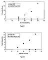
- Figure 1 is a graph showing the viscosity with respect to loading level for modified and unmodified Regal ® 250 carbon black in solvent.
- Figure 2 is a graph showing the yield stress with respect to loading level for modified and unmodified Regal ® 250 carbon black in solvent.
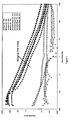
- Figure 3 is a graph showing the viscosity with respect to shear rate for various loading levels of modified and unmodified Regal ® 250 carbon black in solvent.
- Figure 4 is a graph showing the viscosity with respect to loading level for an oxidized and an unoxidized carbon black in solvent.
- Figure 5 is a graph showing the viscosity with respect to loading level for a modified and unmodified carbon black in solvent.
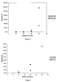
- Figure 6 is a graph showing the viscosity with respect to loading level for modified Pigment Blue 15:6 in solvent.
- Figure 7 is a graph showing the viscosity with respect to loading level for three modified pigments in solvent.
- modified pigments in LTHC layers enables the production of thinner layers exhibiting lower surface roughness than has been previously possible with the use of unmodified pigments.
- Such LTHC layers result in thermal transfer devices that can be used to produce higher resolution patterns with lower line edge roughnesses.
- modified pigments including modified colored pigments, that can be exploited to prepare dispersions that have not previously been used in thermal transfer applications.
- the modified pigment may be an oxidized carbon black.
- the modified pigment may include a pigment having attached at least one organic group.
- the modified pigment may be a pigment having attached at least one attached polymer.
- the modified pigment may be distributed in a matrix, for example, a cross-linked polymer matrix.
- the modified pigment employed in the LTHC layer may be organic, inorganic, or a combination of both.
- the modified pigment absorbs energy at an infrared wavelength, for example, 1064 or 808 nm, and relaxes by releasing thermal energy.
- coatings employed as a LTHC layer and containing modified pigments exhibit an optical density of about 0.2-3 at a desired wavelength, e.g., a wavelength employed to perform light induced thermal transfer.
- the pigment to be modified may be one conventionally used by those of skill in the art for inks, coatings, etc., such as carbonaceous pigments and colored pigments including pigments including a blue, black, brown, cyan, green, white, violet, magenta, red, orange, or yellow pigment. Mixtures of different pigments can also be used.
- suitable carbonaceous pigments include carbon products such as graphite, carbon black, vitreous carbon, carbon fibers, activated charcoal, activated carbon, and carbon nanotubes.
- the carbon may be of the crystalline or amorphous type. Finely divided forms of the above are preferred; also, it is possible to utilize mixtures of different carbons. Of these carbon products, carbon black is preferred.
- carbonaceous pigments include various carbon blacks such as channel blacks, furnace blacks and lamp blacks, and include, for example, carbon blacks sold under the Regal ® , Black Pearls ® , Elftex ® , Monarch ® , Mogul ® , and Vulcan ® trademarks available from Cabot Corporation.
- Suitable classes of colored pigments include, for example, anthraquinones, phthalocyanine blues, phthalocyanine greens, diazos, monoazos, pyranthrones, perylenes, heterocyclic yellows, quinolonoquinolones, quinacridones, and (thio)indigoids.
- Such pigments are commercially available in either powder or press cake form from a number of sources including, BASF Corporation, Engelhard Corporation, and Sun Chemical Corporation.
- colored pigments include, for example, iron oxide pigments (natural and synthetic), chromium oxide pigments, mixed metal oxide pigments, cadmium pigments, bismuth pigments, chromate pigments, ultramarine pigments, iron blue pigments, magnetic pigments, anticorrosive pigments, luster pigments, and luminescent pigments.
- Specific colored pigments include, for example, Prussian Blue (Pigment Blue 27), copper phthalocyanine (Pigment Blue 15) and many of its substituted derivatives, and phthalocyanine-based pigments such as those available from Yamamoto and Avecia. Examples of other suitable colored pigments are described in U.S. Patent Publication No. 20070082288 , the Colour Index, 3rd edition (The Society of Dyers and Colourists, 1982 ) and in Industrial Inorganic Pigments, 1st edition (VCH Publishers, Inc., New York, NY, 1993 ).
- the pigment to be modified may have a wide range of BET surface areas, as measured by nitrogen adsorption, depending on the desired properties of the dispersion. If a higher surface area pigment is not readily available for the desired application, it is also well recognized by those skilled in the art that the pigment may be subjected to conventional size reduction or comminution techniques, such as media, ball or jet milling, to reduce the material to a smaller particle size, if desired. Furthermore, the pigment may exhibit a wide range of structure or branching as measured by dibutylphthalate absorption (DBP) values for carbonaceous pigments or oil absorption values (as described in ISO 787 T5) for colored pigments.
- DBP dibutylphthalate absorption
- the pigment when it is a carbonaceous material such as carbon black, it may be modified by oxidation using an oxidizing agent in order to introduce hydroxyl or ionic and/or ionizable groups onto the surface. Any of the carbon blacks described above can be so oxidized. Oxidized carbonaceous pigments, such as oxidized carbon blacks, prepared in this way have been found to have a higher degree of oxygen-containing groups on the surface.
- Oxidizing agents include, but are not limited to, oxygen gas, ozone, peroxides such as hydrogen peroxide, persulfates, including sodium, potassium, or ammonium persulfate, hypohalites such a sodium hypochlorite, oxidizing acids such as nitric acid, and transition metal containing oxidants, such as permanganate salts, osmium tetroxide, chromium oxides, or ceric ammonium nitrate. Mixtures of oxidants may also be used, particularly mixtures of gaseous oxidants such as oxygen and ozone.
- carbonaceous pigments such as carbon black that are modified using other surface modification methods, such as chlorination and sulfonylation, to introduce ionic or ionizable groups onto a pigment surface, may also be used.
- the modified pigment may alternatively include a pigment having attached at least one organic group.
- the organic group includes at least one ionic group, at least one ionizable group, or a mixture thereof.
- the organic group is directly attached.
- a macromolecule, such as a polymer or oligomer is attached to the pigment.
- the pigment to be modified may be any of those described above.
- the modified pigments may be prepared using any method known to those skilled in the art such that organic chemical groups are attached to the pigment. For example, the modified pigments can be prepared using the methods described in U.S. Patents Nos.
- aqueous solution of a nitrite and an acid are then added separately or together to generate the diazonium reaction and form the diazonium salt, which reacts with the pigment.
- This generation of the diazonium salt is preferably accomplished in situ with the pigment.
- the primary amine group will react to form nitrogen gas or other by-products which will then permit the polymer molecule to attach onto the pigment.
- Such methods provide for a more stable attachment of the groups onto the pigment compared to dispersant type methods, which use, for example, polymers and/or surfactants.
- Other methods for preparing the modified pigments include reacting a pigment having available functional groups with a reagent including the organic group. Such modified pigments may also be prepared using the methods described in the references discussed above.
- modified carbon blacks containing specific functional groups may also be prepared by the methods described in U.S. Patents Nos. 6,831,194 and 6,660,075 , U.S. Patent Publications Nos. 2003-0101901 and 2001-0036994 , Canadian Patent No. 2,351,162 , European Patent No. 1 394 221 , and PCT Publication No. WO 04/63289 .
- the attached organic group may be chosen depending on a variety of factors, including the specific type of solvent, the desired dispersant, as well as the intended use of the dispersion. This allows for greater flexibility by tailoring properties of the modified pigment dispersion.
- the organic group includes at least one ionic group, at least one ionizable group, or a mixture of at least one ionic group and at least one ionizable group.
- An ionic group is either anionic or cationic and is associated with a counterion of the opposite charge including, for example, inorganic or organic counterions such as Na + , K + , Li + , NH 4 + , NR' 4 + , acetate, NO 3 - , SO 4 -2 , OH - , and Cl - , where R' represents hydrogen or an organic group such as a substituted or unsubstituted aryl and/or alkyl group.
- An ionizable group is one that is capable of forming an ionic group in water (not necessarily at pH 7) and is, to some extent, associated with its counterion in a medium of low polarity, unless additives are used to disassociate the counterion.
- Anionizable groups form anions and cationizable groups form cations. Such groups include those described in U. S. Patent No. 5,698,016 .
- the modified pigment includes a pigment having attached at least one chemical group including an anionic group, which is a negatively charged ionic group.
- Anionic groups may be generated from groups having ionizable substituents that can form anions, such as acidic substituents, or may be the anion in the salts of ionizable substituents.
- Representative examples of anionic groups include but are not limited to -COO - , -SO 3 - , -OSO 3 - , -HPO 3 - , -OPO 3 -2 , and -PO 3 -2 .
- anionizable groups include but are not limited to -COOH, -SO 3 H, -PO 3 H 2 , -R'SH, -R'OH, and -SO 2 NHCOR', where R' represents hydrogen or an organic group such as a substituted or unsubstituted aryl and/or alkyl group.
- the attached group includes a carboxylic acid group, a sulfonic acid group, a sulfate group, a carboxylate group, or salts thereof.
- the attached group may be an organic group such as a benzene carboxylic acid group, a benzene dicarboxylic acid group, a benzene tricarboxylic acid group, a benzene sulfonic acid group, or salts thereof.
- organic ionic groups include but are not limited to -C 6 H 4 -CO 2 H, -C 6 H 4 SO 3 H, and salts thereof.
- the attached organic group may also be a substituted derivative of any of these.
- the modified pigment includes a pigment having attached at least one chemical group including a cationic group, which is a positively charged organic ionic group that may be generated from ionizable substituents that can form cations (cationizable groups), such as protonated amines.
- a cationic group which is a positively charged organic ionic group that may be generated from ionizable substituents that can form cations (cationizable groups), such as protonated amines.
- alkyl or aryl amines may be protonated in acidic media to form ammonium groups -NR' 2 H + , where R' represent an organic group such as a substituted or unsubstituted aryl and/or alkyl group.
- Cationic groups may also be positively charged organic ionic groups.
- R' represents hydrogen or an organic group such as a substituted or unsubstituted aryl and/or alkyl group.
- the attached group includes an alkyl amine group or a salt thereof or an alkyl ammonium group.
- the LTHC layer includes a combination product of a modified pigment and a dispersant in a matrix.
- a combination product we mean the product that results from the combination of the modified pigment and the dispersant.
- Specific dispersants can be chosen based on the type of modified pigment and the desired overall properties of the dispersion. For example, if the pigment is a modified pigment having an attached organic group, the dispersant may include at least one functional group chosen based on the organic group attached to the pigment.
- the modified pigment includes a pigment having attached at least one anionic group, at least one anionizable group, or a mixture of these
- dispersants including at least one cationic functional group, at least one cationizable functional group, or a mixture of these can be used to produce dispersions.
- Specific combinations include modified pigments having attached at least one carboxylic acid group, sulfonic acid group, or salt thereof and dispersants including at least one amine group or ammonium group.
- this type of modified pigment to produce dispersions with a dispersant including at least one anionic functional group, at least one anionizable functional group, or a mixture of these.
- the modified pigment includes a pigment having attached at least one cationic group, at least one cationizable group, or a mixture of these
- dispersants including at least one anionic functional group, at least one anionizable functional group, or a mixture of these can be used to produce dispersions.
- dispersants including at least one nonionic functional group such as a polyether group
- Exemplary dispersants that may be employed include but are not limited to BYK108, BYK 115, BYK116, BYK161, BYK163, BYK 182 BYK 2150 and BYK2050, all available from BYK Chemie, Solsperse TM dispersants available from Noveon, including 27-000, 32-000, 32-500, 35-140, 38-500, and 39-000, and K-Sperse 504XD, from King Industries, Inc.
- the amount of dispersant can be varied depending on the type of modified pigment, the solvent, and the loading level of particulate material.
- the ratio of the amount of dispersant to the amount of modified pigment can be between about 0.01 to 1 up to about 2.5 to 1, for example, from about 0.1 to 1 up to about 1 to 1 or in any range defined by any two of the endpoints above.
- the modified pigment is a pigment having an attached polymer.
- an oxidized pigment or a pigment that has been modified to attach a particular chemical group e.g., a carboxylic acid or sulfanilic acid group
- a polymer for example, one of the dispersants described above, having a group that readily participates in a chemical reaction, e.g., a condensation reaction, with the chemical groups on the surface of the oxidized or chemically modified pigment.
- the polymer is directly attached to a pigment.
- a polymer including polymer dispersants described above, having a primary amine or that has been modified to include a primary amine is introduced to or contacted with the pigment. A sufficient amount of time is provided to adsorb the polymer onto the pigment. After adsorption occurs, a diazonium reaction can be conducted as described in U.S. Pat. Nos. 5,571,311 and 5,630,868 , as well as 5,554,739 and PCT Publication WO-96/18688 . Briefly, the polymer is added to the pigment.
- Polymers may be modified to include a primary amine using known techniques to those skilled in the art, such as esterification involving an aromatic or alkyl group and reduction of nitro groups to the corresponding primary amine groups. Nitration of the polymer followed by reduction, or amination of the polymer, are some other techniques that may be used. Modified pigments having attached polymers may also be combined with disperants in dispersions.
- the amount of attached groups, including polymers, on the modified pigments can be varied depending on the solvent and the desired properties of the dispersion.
- the amount of attached groups is from about 0.001 to about 10.0 micromoles of the group per square meter surface area of pigment (surface area as measured, for example, by nitrogen adsorption), for example, about 0.01 ⁇ mol/m 2 to about 8 ⁇ mol/m 2 , about 0.1 ⁇ mol/m 2 to about 7 ⁇ mol/m 2 , about 1 ⁇ mol/m 2 to about 5 ⁇ mol/m 2 , about 2 ⁇ mol/m 2 to about 9 ⁇ mol/m 2 , about 4 ⁇ mol/m 2 to about 6 ⁇ mol/m 2 , about 0.1 ⁇ mol/m 2 to about 4 ⁇ mol/m 2 , about 1 ⁇ mol/m 2 to about 3 ⁇ mol/m 2 , or an amount in any range defined by any two of these endpoints.
- the amount attached can also be varied depending on the characteristics of the specific attached group such as, for example, the size of the attached group or the functionality of the ionic group. Further, it is also within the scope of the present invention to have more than one type of attached group, such as a non-ionic or non-chargeable group, especially one capable of providing additional steric stabilization, on the modified pigment in order to provide for the best overall performance. In this case, the amount of the ionic or ionizable group is preferably greater than amount of the non-ionic group (on a molar basis).
- the modified pigment may be purified by washing, such as by filtration, centrifugation, or a combination of the two methods, to remove unreacted raw materials, byproduct salts, and other reaction impurities.
- the products may also be isolated, for example, by evaporation, including spray drying, or they may be recovered by filtration and drying using techniques known to those skilled in the art.
- the modified pigment can be purified to remove any undesired free species, such as unreacted treating agents used to prepare them. Known techniques of ultrafiltration/diafiltration using a membrane or ion exchange may be used to purify the particulate material and remove a substantial amount of free ionic and unwanted species, if present.
- counterions whereby the counterions that form a part of the modified can be exchanged or substituted with alternative counterions (including, e.g., amphiphilic ions) utilizing known ion exchange techniques such as ultrafiltration, reverse osmosis, ion exchange column, etc, may be employed.
- counterions that can be exchanged include, but are not limited to, Na + , K + , Li + , NH 4 + , Ca 2+ , Mg 2+ , Cl - , NO 3 - , NO 2 - , acetate, and Br - .
- Dispersions using modified pigments are employed to produce LTHC layers according to certain embodiments of the invention.
- “dispersion” we mean a two-phase system including finely divided particles homogeneously distributed throughout a liquid phase.
- the dispersions include a modified pigment, a solvent and an optional dispersant. The viscosity of the dispersion is low, notwithstanding the loading level of the pigment.
- the solvent utilized in the dispersion may have a dielectric constant of at most about 50. Suitable examples include alcohols (such as 1-methyl-2 propanol and methanol), glycols, ethers (such as tetrahydrofuran or diethylether), ketones (such as acetone, methylethyl ketone, or methylbutyl ketone), esters (such as n-butyl propionate), acetates (such as ethyl acetate), amides (such as dimethylformamide), sulfoxides (such as dimethylsulfoxide), hydrocarbons, and miscible mixtures thereof, such as ethylene glycol and methanol.
- the solvent may also include water.
- the solvent is not water alone nor is it a mixture including more than about 50% by weight water.
- the solvent may be a nonaqueous solvent and may further include less than about 50% by weight water, such as at most about 40%, at most about 30%, at most about 20%, or at most about 10% by weight water, or an amount in any range defined by any two of these endpoints.
- the amount of modified pigment present in the dispersion can be varied depending on, for example, the type of modified pigment and the type of solvent.
- the dispersions have a high loading of modified pigment.
- “high” we mean that the amount of modified pigment is at least about 10% by weight based on the total weight of the dispersion.
- the loading level of modified pigment may be at least about 10%, at least about 15%, at least about 20%, at least about 25, or at least about 30% by weight based on the total weight of the dispersion.
- the loading level of modified pigment may be from about 10% to about 55%, from about 15% to about 50%, or from about 30% to about 45%.
- the loading level of modified pigment is at most about 12%, at most about 10%, or at most about 8%.
- the loading level of modified pigment may also be in any range defined by any two of the endpoints described above.
- the dispersion may further include at least one dispersant which forms associative structures in the solvent.
- associative structures is meant an organized arrangement of dispersant molecules resulting from the interaction of groups of the dispersant, such as inverse micelles.
- suitable dispersants include, but are not limited to, polyalkylene oxides (such as polyethylene oxide or polypropylene oxide), polyesters (such as polycaprolactone, polyvalerolactone, poly(hydroxy stearic acid), or poly(hydroxyoleic acid), polyamides such as polycaprolactam, polyacrylates, and block copolymers having both a hydrophobic and a hydrophilic group.
- Additional examples include amine-functionalized derivatives (such as polyamine, tertiary amine, or quaternary ammonium functionalized derivatives) or acid functionalized derivatives (such as carboxylic acid or phosphonic acid functionalized derivatives) of these, such as amine-functionalized or amine-terminated polyalkylene oxides or acrylic polymers including amine or acid functional groups.
- amine-functionalized derivatives such as polyamine, tertiary amine, or quaternary ammonium functionalized derivatives
- acid functionalized derivatives such as carboxylic acid or phosphonic acid functionalized derivatives
- suitable dispersants will be known to one skilled in the art or could be identified by adding the dispersant to the solvent above its critical micelle concentration (CMC) and determining if associative structures, such as inverse micelles, have formed.
- CMC critical micelle concentration
- dispersants that not only form associative structures in the solvent but also form such structures in the dispersion itself - i.e., in the presence of the modified pigment.
- Formation of associative structures for example, by dispersants or polymer groups attached to a pigment, can impart improved properties, such as stability and low viscosity, to high loading dispersions, even when the level of dispersant (when used) is high.
- Techniques such as light scattering methods known to one skilled in the art can be used to detect the presence of such structures in either the solvent or in the dispersion.
- stable dispersions are formed.
- stable we mean that the dispersion properties do not change appreciably over time and/or with changes in a specific condition, for example, temperature.
- the dispersion of modified pigment remains a dispersion.
- the particle size of the modified pigment in the dispersion is at most about 500 nm, preferably at most about 300 nm, more preferably at most about 200 nm, for example, at most about 150 nm.
- Particle size may be measured by dynamic light scattering (DLS), using instruments known to those of skill in the art, for example, particle size analyzers available from Microtrac Inc. (Montgomeryville , PA) and Malvern Instruments Ltd. (Malvern, Worcestershire, UK). If the pigment is a carbon black based pigment, the particle size is the aggregate particle size.
- DLS dynamic light scattering
- the particle size does not change appreciably over time or with variations in temperature, such as elevated temperatures, including greater than about 70°C, greater than about 80°C, or greater than about 90°C.
- the change in average particle size is less than about 10% and more preferably less than about 5% over one week at temperatures greater than 70°C.
- the dispersion does not develop high levels of precipitate over time.
- the solids level of the dispersion remains essentially unchanged. In some embodiments, it has been found that the solids level does not change by more than about 10% and, in some preferred embodiments, by less than about 5% over four weeks at room temperature or two weeks at temperatures greater than 70°C.
- such dispersions can be formed having a viscosity that is at most about 50 cP, even when the modified pigment loading level is high, including more than about 10% by weight. In certain embodiments, the viscosity is at most about 40 cP, about 30 cP, about 20 cP, about 10 cP, or about 5 cP.
- the dispersions can be prepared using any method known in the art.
- the modified pigment and solvent may be combined with agitation to produce a stable dispersion, and, if used, a dispersant may be added.
- the aqueous solvent of this dispersion of the modified pigment may be exchanged for the solvent of the dispersion.
- Exemplary solvent exchange methods include diafiltration/ultrafiltration and addition of the solvent during evaporation of the aqueous solvent.
- a dispersant is used, this can be combined with the modified pigment, and the resulting combination can then be combined with the solvent.
- the modified pigment, optional dispersant, and solvent may be combined in any equipment known in the art, such as a media or ball mill, or other high shear mixing equipment. Various conventional milling media can be used. Other methods for forming the dispersion will be known to one skilled in the art.
- the dispersions may be further purified or classified to remove impurities and other undesirable free species which can co-exist in the dispersion as a result of the manufacturing process.
- the dispersions can be subjected to a classification step, such as filtration, microfiltration, or centrifugation, to substantially remove particles having a size above about 1.0 micron.
- the dispersion is used to prepare the LTHC layer of a donor element for laser-induced thermal imaging by combining the dispersion with other components to form an uncured LTHC layer composition.
- these components include a matrix precursor, such as a curable resin, a polymer, an oligomer, a monomer, or mixtures of any of these.
- a resin as used herein, is any of a class or solid or semi-solid organic products of natural or synthetic origin, generally of high or indefinite molecular weight with no definite melting point. Resins are generally polymeric. Oligomers are low molecular weight polymers at least one of whose chemical, mechanical or other properties exhibit a substantial change when an additional monomer is added to the polymer chain.
- the uncured LTHC layer composition may also include conventional cosolvents such as butyl acetate, ethylcellosolve, ethylcellosolve acetate, butylcellosolve, butylcellosolve acetate, ethylcarbitol, ethylcarbitol acetate, diethyleneglycol, cyclohexanone, propyleneglycol monomethylether, propyleneglycol monomethylether acetate, lactate esters, and mixtures thereof.
- Aqueous solvents may also be added, including, for example, water and water soluble alcohols, but the amount of water will be below 50% by weight.
- the matrix precursor may include any curable resin known in the art.
- exemplary cured resins include but are not limited to phenolic resins, e.g., epoxy bisphenol-A resin or epoxy novolac resin, acrylic resins, methacrylic resins, polystyrene resins, styrene-acrylic resins, poly vinyl butyral, urethane resins, or polyolefin resins.
- the curable resin is one that may be cured thermally or by any source of radiation such as, for example, ultraviolet radiation.
- polymers, oligomers, and monomers in the composition may be thermally or radiation polymerizable or cross-linkable.
- monomers or oligomers of these resins or other resins or polymers such as polyesters, acrylates, methacrylates, epoxides, terminal alkenes, diisocyanates, diols, diamines and styrenics, may be included in the uncured LTHC layer composition in addition to or as alternatives to the cured resins listed above.
- Prepolymers for polyurethanes and polyureas, such as hydroxyl-, amine-, or isocyanate-terminated oligomers may also be employed. In this way, the uncured LTHC layer composition may be photosensitive (i.e.
- the uncured LTHC layer composition may be cured by irradiation) or thermosensitive (i.e., may be cured by changing temperature, such as by heating).
- the uncured LTHC layer composition may further include a photoinitiator, which generates a radical on absorbing light.
- the curable resin, polymer, monomer, or oligomer may be chosen to be compatible (i.e., form a one-phase combination) with the other materials of the uncured LTHC layer composition.
- a solubility parameter can be used to indicate compatibility, as discussed in Polymer Handbook, J. Brandrup, ed., pp. VII 519-557 (1989 ).
- a thermoplastic resin may have a solubility parameter in the range of 9 to 13 (cal/cm 3 ) 1/2 , e.g., 9.5 to 12 (cal/cm 3 ) 1/2 .
- the solubility parameter may also be employed to optimize the choice of modification for the pigment, the solvents and optional dispersants employed in the uncured LTHC layer composition, or any other material used to form the LTHC layer.
- the uncured LTHC layer composition is cured by irradiation in the ultraviolet region of the spectrum (100-400 nm).
- the modified pigment preferably exhibits lower absorption in the ultraviolet than in the infrared (720-1100 nm).
- the LTHC layer can be formed with a minimum of additional components (additives and/or cosolvents) and processing steps.
- additives such as surfactants and cosolvents may also be included.
- a photosensitive resin such as epoxy bisphenol-A or epoxy novolak
- a photoinitiator can also be added.
- One or more monomers, oligomers, and polymers may also be employed.
- the uncured LTHC layer composition can be cured by exposure to UV light (e.g., from a hydrogen or deuterium source) for about 10-20 s at about 100°C.
- the LTHC layer is preferably stable with respect to an MEK rub.
- the uncured LTHC layer composition may also be stable with respect to storage.
- the particle size distribution and or the viscosity does not vary by more than about 10 % after accelerated aging by incubation at 70°C for seven days.
- the amount of solids in the composition does not vary by more than about 5% under similar conditions.
- the uncured LTHC layer composition has very low viscosity.
- the composition may be disposed on a substrate using microgravure printing, spin coating, gravure coating, web coating, dip coating, slit coating, slot coating, or and other techniques that spread a thin layer of fluid on a surface.
- the uncured LTHC layer composition is self leveling, which reduces the formation of irregularities in the final coating and increases smoothness.
- Self-leveling behavior describes a liquid film's ability to flow by maintaining low viscosity and yield stress (the stress beyond which a material is no longer in the linear elastic region of the stress strain curve) as the solid loading level increases during the drying process.
- Uncured LTHC layer compositions containing modified pigments maintain flow at increased solid loading levels, thus enabling self-correction of both imperfections and potential defects in the final film and resulting in smoother, more uniform coatings.
- the uncured LTHC layer composition maintains self-leveling behavior as solvent is removed until the matrix material begins to cure, e.g., at the point where the elastic modulus (G', also called the storage modulus) of the curable coating composition is greater than the loss modulus (G"), a measure of the energy lost by viscous dissipation in a material when mechanical work is applied.
- the proportion of modified pigment in the uncured LTHC layer composition can increase by 50% or more as the solvent is removed from the curable coating composition.
- the uncured LTHC layer composition retains the ability to flow, enabling surface roughness that develops during drying to smooth out.
- the use of a modified pigment provides at least a 10 percentage point improvement, for example, at least a 15 percentage point improvement or at least a 20 percentage point improvement, e.g., between a 10 and 20 or between a 13 and 17 point improvement, or an improvement in any range defined by any of the endpoints above, in the weight percent loading for which self-leveling behavior is observed with respect to the use of an unmodified pigment. That is, the viscosity of a composition including an unmodified pigment dramatically increases with respect to the proportion of carbon black at a loading level far less than the viscosity of an uncured LTHC layer composition according to preferred embodiments of the invention.
- Lower viscosity uncured LTHC layer compositions facilitate the production of thinner LTHC layers, which in turn facilitate the deposition of materials in higher resolution patterns. Even for lower resolution patterns, use of a thinner LTHC layer reduces the lateral diffusion of heat across the LTHC layer.
- materials may be deposited in patterns with sharper edges, e.g., lower line edge roughness.
- the line edge roughness of a transferred material may be from about 5 to about 8 micrometers or less.
- the uncured LTHC layer composition is cured to form the LTHC layer.
- the LTHC layer is at most 4 micrometers thick.
- the LTHC layer is from about 1 to about 4 micrometers thick or in any range defined by any two of these endpoints.
- the LTHC layer has a surface roughness of at most about 1%, at most about 2 %, at most about 5%, at most about 7%, for example, about 4%, as measured as the standard deviation from the median of a scan line taken over a portion of the surface by a profilometer.
- the loading level of the modified pigment in the LTHC layer may be from about 1 wt% to about 30 wt%, for example, from about 3 wt% to about 20 wt% or about 5 wt% to about 15 wt%, or in any range defined by any of these endpoints.
- the loading level is preferably high enough to achieve the desired optical density but low enough to minimize light scattering from the modified pigment during curing (for light-curable matrices) or during irradiation in the course of thermal transfer.
- agglomeration of the modified pigment particles for example, by flocculation, local phase separation, sedimentation, network formation, or creaming, will cause the aforementioned light scattering in the LTHC layer.
- the use of modified pigment reduces agglomeration as compared to unmodified pigments, resulting in decreased viscosity and improved flow behavior of the uncured LTHC layer composition.
- the LTHC layer may be a component of a donor element for laser-induced thermal transfer (LITT).
- exemplary substrate materials for use in a donor element include but are not limited to polyesters, e.g., polyethylene terephthalate and polyethylene naphthanate, polyamides, polycarbonates, fluoropolymers, polyacetals, and polyolefins.
- An adhesion layer may optionally be disposed on this to aid adhesion of the LTHC layer.
- the material for the LTHC layer may be deposited by any film coating method known to those of skill in the art, e.g., roll coating, gravure, extrusion, spin coating, or knife coating.
- the low viscosity of the materials used to produce the LTHC layer enables the use of microgravure printing for production of the LTHC layer.
- Microgravure printing enables the production of thinner films and facilitates the production of more flexible donor elements.
- a transfer layer may be deposited directly on the LTHC layer or over an interlayer disposed on the LTHC layer.
- the interlayer may absorb or reflect at least a portion of the imaging radiation to abate damage to the transfer layer or the receiving substrate that may result from exposure to the imaging radiation.
- the interlayer may also influence the adhesion of the transfer layer to the donor element.
- the interlayer may have high thermal resistance and may also resist thermal or light induced geometrical or chemical changes during imaging.
- the interlayer need not be transferred with the transfer layer and may act as a barrier to the transfer of materials between the transfer layer and the LTHC layer.
- Exemplary interlayer materials include but are not limited to polymers, inorganic materials, and polymer/inorganic composites.
- Inorganic materials may include but are not limited to metals, metal oxides, metal sulfides, and inorganic carbon. Manufacturing methods, materials, and additional description of interlayers for use in LITT are further described in U.S. Patent No. 6,190,826 . Both thermoplastic and thermosetting polymers are appropriate for use as an interlayer material. Additives such as photoinitiators, surfactants, pigments, plasticizers, and coating aids may also be included. The thickness of the interlayer may depend on a variety of factors, e.g., the interlayer material(s), the composition of the LTHC layer, the transfer layer material, the wavelength of the imaging radiation, and the energy of the irradiation (e.g., the intensity and length of the irradiation).
- a release layer may be further interposed between the LTHC layer or the interlayer and the transfer layer.
- Such a layer may facilitate release of the transfer layer from the donor element and, alternatively or in addition, may enhance adhesion of the transfer layer to the donor layer prior to imaging.
- Exemplary release layer materials include but are not limited to electrically conductive and non-conductive thermoplastic polymers, electrically conductive and non-conductive filled polymers, electrically conductive and non-conductive dispersions, and sublimable insulating and semiconducting materials.
- the release layer material may be retained on the donor element or transferred with the transfer layer. Sublimable materials are especially suited for transfer with the transfer layer.
- the transfer layer may include one or more layers to be transferred to the receiving substrate. Any of the layers within the transfer layer may be formed from organic, inorganic, organometallic, or other materials, or mixtures or blends of materials. It is not necessary that the layers of the transfer layer be discrete. There may be interfacial regions where materials from adjacent layers intermix or diffuse into one another, before, during, or after imaging. Indeed, some interfacial interactions may be desired, and the transfer layer may be fabricated to promote those interactions between layers.
- the transfer layer may include materials for a variety of applications, including displays (e.g., for electronic devices such as televisions, computers, personal digital assistants, etc.), "lab on a chip” devices, and electronics.
- the transfer layer may include materials for a color filter, organic light emitting diode (OLED), black matrix, or an alignment layer for a liquid crystal display.
- the transfer layer may include materials for use as sensors, analytes, etc., in lab on a chip devices.
- the transfer layer may include materials for a transparent cathode for electronic applications.
- the transfer layer includes materials for one or more active layers (i.e., a layer that acts as a conducting, semiconducting, electron blocking, hole blocking, light producing (e.g., luminescing, light emitting, fluorescing, or phosphorescing), electron producing, or hole producing layer) for an electronic device.
- the transfer layer may include materials for one or more operational layers (i.e., a layer that acts as an insulating, conducting, semiconducting, electron blocking, hole blocking, light producing, electron producing, hole producing, light absorbing, light reflecting, light diffracting, phase retarding, light scattering, light dispersing, or light diffusing layer) for an electronic device.
- the transfer layer may include materials for one or more non-operational layers (i.e., a layer that does not perform a function in the operation of an electronic device, but serves an alternative function, such as facilitating manufacture or regulating diffusion of materials among layers).
- non-operational layers i.e., a layer that does not perform a function in the operation of an electronic device, but serves an alternative function, such as facilitating manufacture or regulating diffusion of materials among layers.
- the transfer layer may include a biologically active material, e.g., compounds or entities that alter, inhibit, activate, or otherwise affect biological or biochemical events, including both naturally occurring and synthetic materials.
- a biologically active material e.g., compounds or entities that alter, inhibit, activate, or otherwise affect biological or biochemical events, including both naturally occurring and synthetic materials.
- biologically active materials may be used to prepare devices for "lab on a chip” applications, e.g., sensors and microreactors.
- the transfer layer may include a material used to produce one or more components of an LCD display, including for example, a color filter, a black matrix, an alignment layer, or a transparent electrode.
- a dye and/or pigment is present in the transfer layer as the imageable component.
- the imageable component(s) for color filter applications may be chosen such that optical densities on the receiving substrate in areas where material has been transferred are between 1.0 and 2.0 for red, blue and green, and between 3.0 and 4.0 for black.
- a black pigment such as a carbon black or a modified carbon black, may be present in the transfer layer.
- the alignment layer provides a well-defined alignment to the liquid crystals in a display.
- Alignment layers may be produced from organic or inorganic materials.
- the use of LITT to produce alignment layers may obviate rubbing or other manufacturing steps that can introduce particulates or other contaminants into a device.
- Exemplary materials for use in alignment layers include polyimides, among others.
- Transparent electrodes find utility in a wide variety of electronic applications in addition to LCDs and OLEDs.
- transparent electrodes are employed in energy saving windows and in solar panels.
- Exemplary transparent electrode materials include metal oxides such as aluminum or gallium doped zinc oxide, indium oxide, tin oxide, and combinations and compounds of these such as indium tin oxide (ITO), diamond thin films, single wall carbon nanotubes, and intermetallics such as TiW.
- ITO indium tin oxide
- diamond thin films single wall carbon nanotubes
- single wall carbon nanotubes single wall carbon nanotubes
- intermetallics such as TiW.
- the various layers may be added to the donor element using any deposition technique known to those of skill in the art.
- exemplary deposition techniques include but are not limited to printing techniques, e.g., gravure printing, spin coating, spray coating, sputter coating, evaporative coating, chemical vapor deposition, electron beam deposition, extrusion coating, sol-gel techniques, etc.
- a dispersion was prepared by mixing for two hours on a Skandex ® mixer.
- the glass beads were removed using a paint strainer.
- the viscosity of the dispersion (18% modified pigment loading) was measured using a Brookfield viscometer (spindle 18) and found to be 6.48 cP at 100 RPM.
- the mean volume particle size (mV) of the particulate material in the dispersion was measured using a Microtrac ® Particle Size Analyzer and found to be 0.074 ⁇ m.
- a modified pigment including a carbon black having attached sulfonic acid groups prepared according to the procedure in U.S. Patent No. 5,707,432 using 6 ⁇ mol/m 2 sulfanilic acid and Regal ® 330 carbon black and drying down the resulting aqueous dispersion
- 0.82 g Solsperse ® 20000 an amine-functionalized dispersant available from Noveon
- 40.84 g methanol and 49.5 g ethylene glycol as solvent were metered into a vessel.
- the mean volume particle size (mV) of the particulate material in this dispersion (9% modified pigment loading) was measured using a Microtrac ® Particle Size Analyzer and found to be 0.015 ⁇ m. The sample was subjected to accelerated heat aging at 50°C for 3 days, and the mean volume diameter particle size was found to be 0.15 ⁇ m. Similar properties resulted when the ethylene glycol solvent was excluded. Therefore, it would be expected that, if the amount of modified pigment was increased to 10% loading in this formulation, similar results would also be observed.
- Dispersions were prepared with the modified carbon black of Example 1 and Regal ® 250 carbon black in propylene glycol methyletheracetate (PGMEA). The ratio of dispersant (BYK ® 163) to pigment was 0.3 by weight. Dispersions containing 20, 30, 40, and 50% by weight of carbon black were mixed as described in Example 4. The viscosity of the dispersions was measured as described in Example 6. The dispersions were analyzed with a rheometer (ARG2, TA Instrument Ltd Rotational Rheometer) and its software interface (TA Rheology Advantage) to measure the storage and loss moduli, yield strength, and viscosity. Figures 1 and 2 show the viscosity and yield stress, respectively, for mixtures including the modified and unmodified pigment.
- ARG2 TA Instrument Ltd Rotational Rheometer
- TA Rheology Advantage software interface
- Figure 3 shows the variation of the dependence of viscosity on shear rate with loading for both modified and unmodified pigment.
- the advantage of the modified carbon black over the unmodified carbon black is clear. Mixtures with modified carbon blacks maintain low viscosity behavior ( ⁇ 1 Pa.s) and low yield stress behavior ( ⁇ 1 Pa) with upwards of 50 wt% modified pigment, while the mixture with unmodified pigment exhibits a dramatic increase in viscosity and yield stress at only 20 wt% carbon black.
- Dispersions were prepared with Regal ® 400 carbon black, an oxidized carbon black available from Cabot Corporation, and Regal ® 330 carbon black, an unoxidized carbon black available from Cabot Corporation and having a similar morphology, in methyl ethyl ketone (MEK).
- the ratio of dispersant (Solsperse ® 32000) to pigment was 1:2 by weight.
- Dispersions containing 10, 20, 30, and 40% by weight of carbon black were mixed as described in Example 4.
- the viscosity of the dispersions was measured as described in Example 6.
- Figure 4 shows that the viscosity of mixtures including the unoxidized carbon black increases much more quickly with the weight percent of pigment in the mixture than the viscosity of mixtures incorporating the oxidized carbon black.
- Dispersions were prepared with Cab-O-Jet ® 200 colored pigment dispersion, a modified pigment having attached sulfonic acid groups (available from Cabot Corporation, dried down for use herein), and Black Pearls ® 700 carbon black (available from Cabot Corporation) in MEK.
- the ratio of dispersant (Solsperse ® 32000) to pigment was 1:2 by weight.
- Dispersions containing 10, 20, 30, and 40% by weight of pigment were mixed as described in Example 4.
- the viscosity of the dispersions was measured as described in Example 6.
- Figure 5 shows that the viscosity of mixtures including the unmodified carbon black increases much more quickly with the weight percent of pigment in the mixture than the viscosity of mixtures incorporating the modified pigment.
- Dispersions were prepared with PABA (para-amino benzoic acid) - treated Pigment Blue 15:6 (available from DSK) (produced using 2 mmol/g of PABA and a stoichiometric amount of sodium nitrite, the final product was treated with acid to convert the modified pigment to acid form) in diethylene glycol monobutyl ether (DEGBE).
- the ratio of dispersant (BYK ® 2150) to pigment was 1:4 by weight.
- Dispersions containing 15, 20, 25, 30, and 35% by weight of pigment were mixed as described in Example 4. The viscosity of the dispersions was measured as described in Example 6.
- Figure 6 shows that the viscosity of mixtures including the modified pigment increases slowly until the pigment loading in the mixture reached about 25 wt %.
- Dispersions were prepared with Cab-O-Jet ® 554B colored pigment dispersion (dried down for use herein), a violet pigment having attached sulfonic acid groups, sulfonic acid-treated Pigment Red 254 (Ciba) (treated with 6 mmol/g sulfanilic acid, sonicated for four hours, centrifuged, followed by calcium ion exchange to prepare the sulfonate salt form of the modified pigment), and PABA-treated Pigment Blue 15:6 (prepared as in Example 12) in DEGBE.
- the ratio of dispersant (Disperbyk ® 2150) to Cab-O-Jet 554B was 1:1.7.
- the ratio of dispersant (Solsperse ® 32500) to modified Pigment Red 254 was 1:3.3.
- the dispersant and ratio with respect to modified pigment for the modified Pigment Blue 15:6 was as in Example 12.
- Dispersions containing 15, 20, and 25% by weight of pigment were mixed as described in Example 4. Rheological measurements were conducted as described for Example 9 and is shown in Figure 7 .
- the relative viscosity for mixtures incorporating modified pigments did not increase significantly until the pigment loading level reached about 25 wt%.
Abstract
Description
- This invention relates to the exploitation of modified pigments for laser-induced thermal transfer.
- Thermal transfer processes such as, for example, dye sublimation, dye transfer, melt transfer, and ablative material transfer, are well known in applications such as color proofing and lithography. These processes often employ a donor element that includes a layer of material to be transferred ("transfer layer"), and a receiving element that includes a substrate for receiving the transferred material (a "receiving substrate"). The donor element and the receiving substrate are brought into close proximity or direct contact with each other, and portions of the donor element are heated to transfer the corresponding portions of the transfer layer to the receiving substrate. Heat may be generated using a heating element (e.g., a resistive heating element), converting radiation (e.g., light) to heat, and/or applying an electrical current to a layer of the thermal transfer element.
- In a digital transfer process, the exposure to radiation takes place only in a small, selected region of the assembly of the donor element and receiving substrate at one time, so that transfer of material from the donor element to the receiving substrate occurs in a patterned manner. Thus, a non-patterned donor is in this manner selectively transferred to a receiving substrate in a patterned manner. Computer control facilitates high resolution and high speed transfer. Alternatively, in an analog process, the entire assembly may be irradiated and a mask may be used to selectively expose desired portions of the thermally imageable layer. See, for example,
U.S. Pats. Nos. 5,857,709 and 5,937,272 . - Patterning materials using thermal transfer processes is generally faster and less expensive and can provide greater resolution than patterning by using photolithographic processes. Thermal transfer using light can also provide better accuracy and quality control for very small devices, such as small optical and electronic devices, including, for example, transistors and other components of integrated circuits, as well as components for use in a display, such as electroluminescent lamps and control circuitry. The size and shape of the transferred pattern (e.g., a line, circle, square, or other shape) can be controlled by, for example, selecting the size of the light beam, the exposure pattern of the light beam, the duration of directed beam contact with the thermal transfer element, and the materials of the thermal transfer element. Moreover, thermal transfer using light may, at least in some instances, provide for better registration when forming multiple devices over an area that is large compared to the device size. Methods and devices for performing light-induced thermal transfer are known to those of skill in the art and are described in
U.S. Patents Nos. 6,194,119 ;7,108,949 ;6,921,614 ;5,523,019 ; and6,855,384 . - Thermal transfer to pattern layers from donor elements can also be useful to de-couple layer coating steps from patterning steps, for example where such coupling can limit the types of layered structures, or the types of adjacent structures, that can be patterned. Because no solvent is required for thermal transfer, materials can be patterned that may be sensitive to the various solvents are employed in prior art lithographic methods. Conversely, materials may also be patterned without concern that solvents may adversely affect previously deposited materials. Biological materials especially may be patterned without risking denaturation of proteins or the interruption of hydrogen bonds between or within nucleic acid molecules.
- In some donor elements, a separate heat generating layer is employed. The heat generating layer may be a light to heat conversion (LTHC) layer incorporating a material that absorbs a desired wavelength of radiation and converts at least a portion of the incident radiation to heat. The heat from the LTHC layer heats the transfer layer, causing the material to be transferred to the receiving substrate.
- LTHC layers have employed pigments such as carbon black in polymer compositions (see, for example,
U.S. Patents Nos. 5,695,907 ,5,863,860 ,6,190,826 , and6,194,119 ). Such pigments are finely divided, insoluble, solid particles which are, in general, not readily dispersible in liquid vehicles. - Difficulties with dispersion of the pigment generates a number of disadvantages for the production of thermal transfer devices. Where a separate LTHC layer is employed, the inability to incorporate sufficient amounts of pigment into the LTHC layer can reduce the optical density of the LTHC layer, increasing the amount of light required to accomplish thermal transfer. While dispersants may be used to facilitate dispersion of the pigment, these can increase the viscosity of the dispersion. High viscosity dispersions increase the difficulty of manufacturing layers incorporating these dispersions. Known techniques for producing thin layers, e.g., microgravure printing, may not be suitable for use with high viscosity media, and thicker layers may be required to avoid pinholes and other defects. However, thicker layers result in increased materials expenses during manufacturing and also increase the amount of light required to accomplish thermal transfer, as it will take longer to heat the thicker layer. Furthermore, because it takes longer to conduct heat across the thickness of a thicker LTHC layer, heat will convect laterally along the LTHC layer, further decreasing the resolution of the thermal transfer device.
US 2002/0020318 A1 relates to printing plates comprising a radiation absorptive layer having a thickness of 20 to 25 µm, wherein the radiation-absorptive layer comprises at least one modified pigment having attached at least one organic group and at least one amphiphilic counter ion. InUS 2002/0011185 A1 modified pigment products having attached at least one organic group are disclosed. These pigments can be used in several applications, such as printing plates, electrophoretic displays, liquid crystal displays and ink, coating, toner and polymer compositions.
US 2005/0287315 A1 relates to a thermal transfer donor element comprising a support, a light-to-heat conversion (LTHC) layer, an interlayer and a thermal transfer layer, wherein the LTHC layer has a thickness of 0.001 to 20 µm and a surface roughness of less than 10%.
Thus, it is desirable to have thinner, smoother LTHC layers without sacrificing optical density for use in light induced thermal transfer since they can be used to deliver images with higher resolution and lower line edge roughness at lower materials cost. - In one aspect, the invention includes a light to heat conversion (LTHC) layer comprising a light absorbing material and a matrix in which the light absorbing material is dispersed, the LTHC layer having a surface roughness of at most 7% and a thickness of at most 4 micrometers,
wherein the light absorbing material is a) a combination product of a dispersant and a modified pigment, the modified pigment comprising i) a pigment having attached at least one organic group comprising an ionic or an ionizable group or ii) an oxidized carbon black or b) a modified pigment comprising a pigment having attached at least one polymer and, optionally, a dispersant.
The matrix may include a polymer or a resin, or both. The LTHC layer may include from about 10% to about 55% of the modified pigment by weight. The pigment may be a carbonaceous pigment or a colored pigment, for example, a carbon black. The organic group may include at least one carboxylic acid group, at least one sulfonic acid group, a salt of either of the above, or at least one a hydroxyl group, for example, a C6H4-COOH group, a -C6H4-SO3H group, or a salt of either of the above. The LTHC layer may have an optical density from about 0.2 to about 3 at a predetermined wavelength, which may be in the infrared portion of the electromagnetic spectrum. - In another aspect, the invention includes a thermal transfer donor element. The thermal transfer donor element includes the LTHC layer. The thermal transfer donor element may further include a substrate supporting the LTHC layer, an adhesion layer disposed between the substrate and the LTHC layer, a transfer layer, and/or an interlayer disposed between the transfer layer and the LTHC layer. The transfer layer may include a biologically active material, a material for a color filter, a material for a black matrix, a material for an organic light emitting diode, a material for an alignment layer for a liquid crystal display, or a material for a transparent electrode.
- In another aspect, the invention includes a method for producing a thermal transfer donor element or a LTHC layer, comprising: providing a substrate;
combining a modified pigment concentrate, a solvent and a matrix precursor comprising one or more of at least one monomer, at least one oligomer, at least one polymer, and at least one resin to form a mixture, wherein the modified pigment concentrate comprises a) a combination product of a dispersant with a modified pigment comprising i) a pigment having attached at least one organic group comprising an ionic or an ionizable group or ii) an oxidized carbon black or b) a modified pigment comprising a pigment having attached at least one polymer and, optionally, a dispersant;
disposing the mixture over the substrate; and
removing the solvent from the disposed mixture to form a modified pigment-containing layer characterized by a thickness of at most 4 micrometers and a surface roughness of at most 7%. - The method may further include curing the matrix precursor to form a matrix in which the combination product is dispersed, and curing may include irradiating the mixture at a predetermined wavelength or bringing the mixture to a temperature at which the monomer polymerizes. The method may further include disposing an adhesion layer over the substrate, wherein disposing the mixture includes disposing the mixture over the adhesion layer. The method may further include disposing a transfer layer over the modified pigment-containing layer and/or disposing an interlayer between the modified pigment-containing layer and the transfer layer. The mixture may further include an initiator, an adhesion promoter, or both and/or may have a viscosity less than 50 cP. Disposing the mixture may include using one or more of microgravure coating, spin coating, gravure printing, web coating, dip coating, slit coating, and slot coating.
- In another aspect, the invention includes a method of performing laser induced thermal transfer. The method includes providing a thermal transfer donor element including a substrate and the LTHC layer supported by the substrate, the thermal transfer donor element having a transfer layer disposed thereon; placing the thermal transfer donor element against a receiving substrate; and irradiating at least a portion of the thermal transfer donor element with sufficient energy in a predetermined pattern to transfer at least a portion of the transfer layer to the receiving substrate according to the predetermined pattern.
- The surface roughness of the LTHC layer is at most 7%. The transfer layer may include a polymer matrix. The transfer layer may include a biologically active material, a material for a color filter, a material for a black matrix, a material for an organic light emitting diode, a material for an alignment layer for a liquid crystal display, or a material for a transparent electrode.
- It is to be understood that both the foregoing general description and the following detailed description are exemplary and explanatory only and are intended to provide further explanation of the present invention, as claimed.
- The invention is described with reference to the several figures of the drawing, in which,
-
Figure 1 is a graph showing the viscosity with respect to loading level for modified andunmodified Regal ® 250 carbon black in solvent. -
Figure 2 is a graph showing the yield stress with respect to loading level for modified andunmodified Regal ® 250 carbon black in solvent. -
Figure 3 is a graph showing the viscosity with respect to shear rate for various loading levels of modified andunmodified Regal ® 250 carbon black in solvent. -
Figure 4 is a graph showing the viscosity with respect to loading level for an oxidized and an unoxidized carbon black in solvent. -
Figure 5 is a graph showing the viscosity with respect to loading level for a modified and unmodified carbon black in solvent. -
Figure 6 is a graph showing the viscosity with respect to loading level for modified Pigment Blue 15:6 in solvent. -
Figure 7 is a graph showing the viscosity with respect to loading level for three modified pigments in solvent. - We have discovered that the use of modified pigments in LTHC layers enables the production of thinner layers exhibiting lower surface roughness than has been previously possible with the use of unmodified pigments. Such LTHC layers result in thermal transfer devices that can be used to produce higher resolution patterns with lower line edge roughnesses. We have developed modified pigments, including modified colored pigments, that can be exploited to prepare dispersions that have not previously been used in thermal transfer applications. The modified pigment may be an oxidized carbon black. Alternatively, the modified pigment may include a pigment having attached at least one organic group. In another embodiment, the modified pigment may be a pigment having attached at least one attached polymer. The modified pigment may be distributed in a matrix, for example, a cross-linked polymer matrix. The modified pigment employed in the LTHC layer may be organic, inorganic, or a combination of both. Preferably, the modified pigment absorbs energy at an infrared wavelength, for example, 1064 or 808 nm, and relaxes by releasing thermal energy. In preferred embodiments, coatings employed as a LTHC layer and containing modified pigments exhibit an optical density of about 0.2-3 at a desired wavelength, e.g., a wavelength employed to perform light induced thermal transfer.
- The pigment to be modified may be one conventionally used by those of skill in the art for inks, coatings, etc., such as carbonaceous pigments and colored pigments including pigments including a blue, black, brown, cyan, green, white, violet, magenta, red, orange, or yellow pigment. Mixtures of different pigments can also be used. Examples of suitable carbonaceous pigments include carbon products such as graphite, carbon black, vitreous carbon, carbon fibers, activated charcoal, activated carbon, and carbon nanotubes. The carbon may be of the crystalline or amorphous type. Finely divided forms of the above are preferred; also, it is possible to utilize mixtures of different carbons. Of these carbon products, carbon black is preferred.
- Representative examples of carbonaceous pigments include various carbon blacks such as channel blacks, furnace blacks and lamp blacks, and include, for example, carbon blacks sold under the Regal®, Black Pearls®, Elftex®, Monarch®, Mogul®, and Vulcan® trademarks available from Cabot Corporation. Examples of these include but are not limited to Black Pearls® 2000, Black Pearls® 1400, Black Pearls® 1300, Black Pearls® 1100,
Black Pearls ® 1000, Black Pearls® 900, Black Pearls® 880, Black Pearls® 800, Black Pearls® 700, Black Pearls® L,Elftex ® 8, Monarch® 1400, Monarch® 1300, Monarch® 1100,Monarch ® 1000, Monarch® 900, Monarch® 880, Monarch® 800, Monarch® 700, Mogul® L, Regal® 330, Regal® 400, and Vulcan® P. - Suitable classes of colored pigments include, for example, anthraquinones, phthalocyanine blues, phthalocyanine greens, diazos, monoazos, pyranthrones, perylenes, heterocyclic yellows, quinolonoquinolones, quinacridones, and (thio)indigoids. Such pigments are commercially available in either powder or press cake form from a number of sources including, BASF Corporation, Engelhard Corporation, and Sun Chemical Corporation. Additional classes of colored pigments include, for example, iron oxide pigments (natural and synthetic), chromium oxide pigments, mixed metal oxide pigments, cadmium pigments, bismuth pigments, chromate pigments, ultramarine pigments, iron blue pigments, magnetic pigments, anticorrosive pigments, luster pigments, and luminescent pigments. Specific colored pigments include, for example, Prussian Blue (Pigment Blue 27), copper phthalocyanine (Pigment Blue 15) and many of its substituted derivatives, and phthalocyanine-based pigments such as those available from Yamamoto and Avecia. Examples of other suitable colored pigments are described in
U.S. Patent Publication No. 20070082288 , the Colour Index, 3rd edition (The Society of Dyers and Colourists, 1982) and in Industrial Inorganic Pigments, 1st edition (VCH Publishers, Inc., New York, NY, 1993). - The pigment to be modified may have a wide range of BET surface areas, as measured by nitrogen adsorption, depending on the desired properties of the dispersion. If a higher surface area pigment is not readily available for the desired application, it is also well recognized by those skilled in the art that the pigment may be subjected to conventional size reduction or comminution techniques, such as media, ball or jet milling, to reduce the material to a smaller particle size, if desired. Furthermore, the pigment may exhibit a wide range of structure or branching as measured by dibutylphthalate absorption (DBP) values for carbonaceous pigments or oil absorption values (as described in ISO 787 T5) for colored pigments.
- When the pigment is a carbonaceous material such as carbon black, it may be modified by oxidation using an oxidizing agent in order to introduce hydroxyl or ionic and/or ionizable groups onto the surface. Any of the carbon blacks described above can be so oxidized. Oxidized carbonaceous pigments, such as oxidized carbon blacks, prepared in this way have been found to have a higher degree of oxygen-containing groups on the surface. Oxidizing agents include, but are not limited to, oxygen gas, ozone, peroxides such as hydrogen peroxide, persulfates, including sodium, potassium, or ammonium persulfate, hypohalites such a sodium hypochlorite, oxidizing acids such as nitric acid, and transition metal containing oxidants, such as permanganate salts, osmium tetroxide, chromium oxides, or ceric ammonium nitrate. Mixtures of oxidants may also be used, particularly mixtures of gaseous oxidants such as oxygen and ozone. In addition, carbonaceous pigments such as carbon black that are modified using other surface modification methods, such as chlorination and sulfonylation, to introduce ionic or ionizable groups onto a pigment surface, may also be used.
- The modified pigment may alternatively include a pigment having attached at least one organic group. Preferably, the organic group includes at least one ionic group, at least one ionizable group, or a mixture thereof. In some embodiments, the organic group is directly attached. In other embodiments, a macromolecule, such as a polymer or oligomer is attached to the pigment. The pigment to be modified may be any of those described above. The modified pigments may be prepared using any method known to those skilled in the art such that organic chemical groups are attached to the pigment. For example, the modified pigments can be prepared using the methods described in
U.S. Patents Nos. 5,554,739 ,5,707,432 ,5,837,045 ,5,851,280 ,5,885,335 ,5,895,522 ,5,900,029 ,5,922,118 ,6,042,643 ,6,664,312 ,6,551,393 ,6,372,820 ,6,368,239 ,6,350,519 ,6,337,358 , and6,102,380 ,PCT Publication WO 99/23174 U.S. Patent Publication No. 20060211791 . Briefly, the material being attached to the pigment and the pigment are combined. An aqueous solution of a nitrite and an acid are then added separately or together to generate the diazonium reaction and form the diazonium salt, which reacts with the pigment. This generation of the diazonium salt is preferably accomplished in situ with the pigment. In the diazonium reaction, the primary amine group will react to form nitrogen gas or other by-products which will then permit the polymer molecule to attach onto the pigment. Such methods provide for a more stable attachment of the groups onto the pigment compared to dispersant type methods, which use, for example, polymers and/or surfactants. Other methods for preparing the modified pigments include reacting a pigment having available functional groups with a reagent including the organic group. Such modified pigments may also be prepared using the methods described in the references discussed above. In addition, modified carbon blacks containing specific functional groups may also be prepared by the methods described inU.S. Patents Nos. 6,831,194 and6,660,075 ,U.S. Patent Publications Nos. 2003-0101901 and2001-0036994 , Canadian Patent No.2,351,162 , European Patent No.1 394 221 , andPCT Publication No. WO 04/63289 - The attached organic group may be chosen depending on a variety of factors, including the specific type of solvent, the desired dispersant, as well as the intended use of the dispersion. This allows for greater flexibility by tailoring properties of the modified pigment dispersion. In a preferred embodiment, the organic group includes at least one ionic group, at least one ionizable group, or a mixture of at least one ionic group and at least one ionizable group. An ionic group is either anionic or cationic and is associated with a counterion of the opposite charge including, for example, inorganic or organic counterions such as Na+, K+, Li+, NH4 +, NR'4 +, acetate, NO3 -, SO4 -2, OH-, and Cl-, where R' represents hydrogen or an organic group such as a substituted or unsubstituted aryl and/or alkyl group. An ionizable group is one that is capable of forming an ionic group in water (not necessarily at pH 7) and is, to some extent, associated with its counterion in a medium of low polarity, unless additives are used to disassociate the counterion. Anionizable groups form anions and cationizable groups form cations. Such groups include those described in
U. S. Patent No. 5,698,016 . - In certain embodiments, the modified pigment includes a pigment having attached at least one chemical group including an anionic group, which is a negatively charged ionic group. Anionic groups may be generated from groups having ionizable substituents that can form anions, such as acidic substituents, or may be the anion in the salts of ionizable substituents. Representative examples of anionic groups include but are not limited to -COO-, -SO3 -, -OSO3 -, -HPO3 -, -OPO3 -2, and -PO3 -2. Representative examples of anionizable groups include but are not limited to -COOH, -SO3H, -PO3H2, -R'SH, -R'OH, and -SO2NHCOR', where R' represents hydrogen or an organic group such as a substituted or unsubstituted aryl and/or alkyl group. Preferably, the attached group includes a carboxylic acid group, a sulfonic acid group, a sulfate group, a carboxylate group, or salts thereof. For example, the attached group may be an organic group such as a benzene carboxylic acid group, a benzene dicarboxylic acid group, a benzene tricarboxylic acid group, a benzene sulfonic acid group, or salts thereof. Specific organic ionic groups include but are not limited to -C6H4-CO2H, -C6H4SO3H, and salts thereof. The attached organic group may also be a substituted derivative of any of these.
- In certain embodiments, the modified pigment includes a pigment having attached at least one chemical group including a cationic group, which is a positively charged organic ionic group that may be generated from ionizable substituents that can form cations (cationizable groups), such as protonated amines. For example, alkyl or aryl amines may be protonated in acidic media to form ammonium groups -NR'2H +, where R' represent an organic group such as a substituted or unsubstituted aryl and/or alkyl group. Cationic groups may also be positively charged organic ionic groups. Examples include but are not limited to quaternary ammonium groups (-NR'3 +) and quaternary phosphonium groups (-PR'3 +). Here, R' represents hydrogen or an organic group such as a substituted or unsubstituted aryl and/or alkyl group. Preferably, the attached group includes an alkyl amine group or a salt thereof or an alkyl ammonium group.
- In certain embodiments, the LTHC layer includes a combination product of a modified pigment and a dispersant in a matrix. By "combination product", we mean the product that results from the combination of the modified pigment and the dispersant. Specific dispersants can be chosen based on the type of modified pigment and the desired overall properties of the dispersion. For example, if the pigment is a modified pigment having an attached organic group, the dispersant may include at least one functional group chosen based on the organic group attached to the pigment. For example, if the modified pigment includes a pigment having attached at least one anionic group, at least one anionizable group, or a mixture of these, it has been found that dispersants including at least one cationic functional group, at least one cationizable functional group, or a mixture of these can be used to produce dispersions. Specific combinations include modified pigments having attached at least one carboxylic acid group, sulfonic acid group, or salt thereof and dispersants including at least one amine group or ammonium group. However, it is also possible, for this type of modified pigment, to produce dispersions with a dispersant including at least one anionic functional group, at least one anionizable functional group, or a mixture of these. Furthermore, if the modified pigment includes a pigment having attached at least one cationic group, at least one cationizable group, or a mixture of these, it has been found that dispersants including at least one anionic functional group, at least one anionizable functional group, or a mixture of these can be used to produce dispersions. Finally, it has also been found that dispersants including at least one nonionic functional group (such as a polyether group) can be used to produce dispersions if the modified pigment includes a pigment having attached at least one ionic group, at least one ionizable group, or a mixture of these.
- Exemplary dispersants that may be employed include but are not limited to BYK108,
BYK 115, BYK116, BYK161, BYK163, BYK 182 BYK 2150 and BYK2050, all available from BYK Chemie, Solsperse™ dispersants available from Noveon, including 27-000, 32-000, 32-500, 35-140, 38-500, and 39-000, and K-Sperse 504XD, from King Industries, Inc. - The amount of dispersant can be varied depending on the type of modified pigment, the solvent, and the loading level of particulate material. In general, the ratio of the amount of dispersant to the amount of modified pigment can be between about 0.01 to 1 up to about 2.5 to 1, for example, from about 0.1 to 1 up to about 1 to 1 or in any range defined by any two of the endpoints above.
- In certain embodiments, the modified pigment is a pigment having an attached polymer. In one embodiment, an oxidized pigment or a pigment that has been modified to attach a particular chemical group, e.g., a carboxylic acid or sulfanilic acid group, is reacted with a polymer, for example, one of the dispersants described above, having a group that readily participates in a chemical reaction, e.g., a condensation reaction, with the chemical groups on the surface of the oxidized or chemically modified pigment.
- In another embodiment, the polymer is directly attached to a pigment. For example, a polymer, including polymer dispersants described above, having a primary amine or that has been modified to include a primary amine is introduced to or contacted with the pigment. A sufficient amount of time is provided to adsorb the polymer onto the pigment. After adsorption occurs, a diazonium reaction can be conducted as described in
U.S. Pat. Nos. 5,571,311 and5,630,868 , as well as5,554,739 andPCT Publication WO-96/18688 - The amount of attached groups, including polymers, on the modified pigments can be varied depending on the solvent and the desired properties of the dispersion. In certain embodiments, the amount of attached groups is from about 0.001 to about 10.0 micromoles of the group per square meter surface area of pigment (surface area as measured, for example, by nitrogen adsorption), for example, about 0.01 µmol/m2 to about 8 µmol/m2, about 0.1 µmol/m2 to about 7 µmol/m2, about 1 µmol/m2 to about 5 µmol/m2, about 2 µmol/m2 to about 9 µmol/m2, about 4 µmol/m2 to about 6 µmol/m2, about 0.1 µmol/m2 to about 4 µmol/m2, about 1 µmol/m2 to about 3 µmol/m2, or an amount in any range defined by any two of these endpoints. The amount attached can also be varied depending on the characteristics of the specific attached group such as, for example, the size of the attached group or the functionality of the ionic group. Further, it is also within the scope of the present invention to have more than one type of attached group, such as a non-ionic or non-chargeable group, especially one capable of providing additional steric stabilization, on the modified pigment in order to provide for the best overall performance. In this case, the amount of the ionic or ionizable group is preferably greater than amount of the non-ionic group (on a molar basis).
- The modified pigment may be purified by washing, such as by filtration, centrifugation, or a combination of the two methods, to remove unreacted raw materials, byproduct salts, and other reaction impurities. The products may also be isolated, for example, by evaporation, including spray drying, or they may be recovered by filtration and drying using techniques known to those skilled in the art. In addition, the modified pigment can be purified to remove any undesired free species, such as unreacted treating agents used to prepare them. Known techniques of ultrafiltration/diafiltration using a membrane or ion exchange may be used to purify the particulate material and remove a substantial amount of free ionic and unwanted species, if present. Also, an optional exchange of counterions whereby the counterions that form a part of the modified can be exchanged or substituted with alternative counterions (including, e.g., amphiphilic ions) utilizing known ion exchange techniques such as ultrafiltration, reverse osmosis, ion exchange column, etc, may be employed. Particular examples of counterions that can be exchanged include, but are not limited to, Na+, K+, Li+, NH4 +, Ca2+, Mg2+, Cl-, NO3 -, NO2 -, acetate, and Br-.
- Dispersions using modified pigments are employed to produce LTHC layers according to certain embodiments of the invention. By "dispersion", we mean a two-phase system including finely divided particles homogeneously distributed throughout a liquid phase. The dispersions include a modified pigment, a solvent and an optional dispersant. The viscosity of the dispersion is low, notwithstanding the loading level of the pigment.
- The solvent utilized in the dispersion may have a dielectric constant of at most about 50. Suitable examples include alcohols (such as 1-methyl-2 propanol and methanol), glycols, ethers (such as tetrahydrofuran or diethylether), ketones (such as acetone, methylethyl ketone, or methylbutyl ketone), esters (such as n-butyl propionate), acetates (such as ethyl acetate), amides (such as dimethylformamide), sulfoxides (such as dimethylsulfoxide), hydrocarbons, and miscible mixtures thereof, such as ethylene glycol and methanol. The solvent may also include water. In some embodiments, the solvent is not water alone nor is it a mixture including more than about 50% by weight water. For example, the solvent may be a nonaqueous solvent and may further include less than about 50% by weight water, such as at most about 40%, at most about 30%, at most about 20%, or at most about 10% by weight water, or an amount in any range defined by any two of these endpoints.
- The amount of modified pigment present in the dispersion can be varied depending on, for example, the type of modified pigment and the type of solvent. In some embodiments, the dispersions have a high loading of modified pigment. By "high", we mean that the amount of modified pigment is at least about 10% by weight based on the total weight of the dispersion. For example, the loading level of modified pigment may be at least about 10%, at least about 15%, at least about 20%, at least about 25, or at least about 30% by weight based on the total weight of the dispersion. For example, the loading level of modified pigment may be from about 10% to about 55%, from about 15% to about 50%, or from about 30% to about 45%. In alternative embodiments, the loading level of modified pigment is at most about 12%, at most about 10%, or at most about 8%. The loading level of modified pigment may also be in any range defined by any two of the endpoints described above.
- The dispersion may further include at least one dispersant which forms associative structures in the solvent. By "associative structures" is meant an organized arrangement of dispersant molecules resulting from the interaction of groups of the dispersant, such as inverse micelles. Examples of suitable dispersants include, but are not limited to, polyalkylene oxides (such as polyethylene oxide or polypropylene oxide), polyesters (such as polycaprolactone, polyvalerolactone, poly(hydroxy stearic acid), or poly(hydroxyoleic acid), polyamides such as polycaprolactam, polyacrylates, and block copolymers having both a hydrophobic and a hydrophilic group. Additional examples include amine-functionalized derivatives (such as polyamine, tertiary amine, or quaternary ammonium functionalized derivatives) or acid functionalized derivatives (such as carboxylic acid or phosphonic acid functionalized derivatives) of these, such as amine-functionalized or amine-terminated polyalkylene oxides or acrylic polymers including amine or acid functional groups. Other suitable dispersants will be known to one skilled in the art or could be identified by adding the dispersant to the solvent above its critical micelle concentration (CMC) and determining if associative structures, such as inverse micelles, have formed. Particularly preferred are those dispersants that not only form associative structures in the solvent but also form such structures in the dispersion itself - i.e., in the presence of the modified pigment. Formation of associative structures, for example, by dispersants or polymer groups attached to a pigment, can impart improved properties, such as stability and low viscosity, to high loading dispersions, even when the level of dispersant (when used) is high. Techniques such as light scattering methods known to one skilled in the art can be used to detect the presence of such structures in either the solvent or in the dispersion.
- In certain preferred embodiments, stable dispersions are formed. By "stable", we mean that the dispersion properties do not change appreciably over time and/or with changes in a specific condition, for example, temperature. The dispersion of modified pigment remains a dispersion.
- In some embodiments, the particle size of the modified pigment in the dispersion is at most about 500 nm, preferably at most about 300 nm, more preferably at most about 200 nm, for example, at most about 150 nm. Particle size may be measured by dynamic light scattering (DLS), using instruments known to those of skill in the art, for example, particle size analyzers available from Microtrac Inc. (Montgomeryville , PA) and Malvern Instruments Ltd. (Malvern, Worcestershire, UK). If the pigment is a carbon black based pigment, the particle size is the aggregate particle size. Preferably, the particle size does not change appreciably over time or with variations in temperature, such as elevated temperatures, including greater than about 70°C, greater than about 80°C, or greater than about 90°C. Preferably, the change in average particle size is less than about 10% and more preferably less than about 5% over one week at temperatures greater than 70°C. We have found that dispersions according to various embodiments exhibit these characteristics even at the high particulate material loading levels described above.
- Alternatively or in addition, the dispersion does not develop high levels of precipitate over time. Thus, the solids level of the dispersion remains essentially unchanged. In some embodiments, it has been found that the solids level does not change by more than about 10% and, in some preferred embodiments, by less than about 5% over four weeks at room temperature or two weeks at temperatures greater than 70°C.
- It has further been found that such dispersions can be formed having a viscosity that is at most about 50 cP, even when the modified pigment loading level is high, including more than about 10% by weight. In certain embodiments, the viscosity is at most about 40 cP, about 30 cP, about 20 cP, about 10 cP, or about 5 cP.
- The dispersions can be prepared using any method known in the art. For example, the modified pigment and solvent may be combined with agitation to produce a stable dispersion, and, if used, a dispersant may be added. Also, if the modified pigment is dispersible in water, the aqueous solvent of this dispersion of the modified pigment may be exchanged for the solvent of the dispersion. Exemplary solvent exchange methods include diafiltration/ultrafiltration and addition of the solvent during evaporation of the aqueous solvent. Alternatively, if a dispersant is used, this can be combined with the modified pigment, and the resulting combination can then be combined with the solvent. The modified pigment, optional dispersant, and solvent may be combined in any equipment known in the art, such as a media or ball mill, or other high shear mixing equipment. Various conventional milling media can be used. Other methods for forming the dispersion will be known to one skilled in the art.
- The dispersions may be further purified or classified to remove impurities and other undesirable free species which can co-exist in the dispersion as a result of the manufacturing process. For example, the dispersions can be subjected to a classification step, such as filtration, microfiltration, or centrifugation, to substantially remove particles having a size above about 1.0 micron.
- The dispersion is used to prepare the LTHC layer of a donor element for laser-induced thermal imaging by combining the dispersion with other components to form an uncured LTHC layer composition. These components include a matrix precursor, such as a curable resin, a polymer, an oligomer, a monomer, or mixtures of any of these.
- A resin, as used herein, is any of a class or solid or semi-solid organic products of natural or synthetic origin, generally of high or indefinite molecular weight with no definite melting point. Resins are generally polymeric. Oligomers are low molecular weight polymers at least one of whose chemical, mechanical or other properties exhibit a substantial change when an additional monomer is added to the polymer chain.
- The uncured LTHC layer composition may also include conventional cosolvents such as butyl acetate, ethylcellosolve, ethylcellosolve acetate, butylcellosolve, butylcellosolve acetate, ethylcarbitol, ethylcarbitol acetate, diethyleneglycol, cyclohexanone, propyleneglycol monomethylether, propyleneglycol monomethylether acetate, lactate esters, and mixtures thereof. Aqueous solvents may also be added, including, for example, water and water soluble alcohols, but the amount of water will be below 50% by weight.
- The matrix precursor may include any curable resin known in the art. Exemplary cured resins include but are not limited to phenolic resins, e.g., epoxy bisphenol-A resin or epoxy novolac resin, acrylic resins, methacrylic resins, polystyrene resins, styrene-acrylic resins, poly vinyl butyral, urethane resins, or polyolefin resins. The curable resin is one that may be cured thermally or by any source of radiation such as, for example, ultraviolet radiation. Likewise, polymers, oligomers, and monomers in the composition may be thermally or radiation polymerizable or cross-linkable. For example, monomers or oligomers of these resins or other resins or polymers, such as polyesters, acrylates, methacrylates, epoxides, terminal alkenes, diisocyanates, diols, diamines and styrenics, may be included in the uncured LTHC layer composition in addition to or as alternatives to the cured resins listed above. Prepolymers for polyurethanes and polyureas, such as hydroxyl-, amine-, or isocyanate-terminated oligomers, may also be employed. In this way, the uncured LTHC layer composition may be photosensitive (i.e. may be cured by irradiation) or thermosensitive (i.e., may be cured by changing temperature, such as by heating). When the components of the uncured LTHC layer composition are curable by irradiation, the uncured LTHC layer composition may further include a photoinitiator, which generates a radical on absorbing light.
- The curable resin, polymer, monomer, or oligomer may be chosen to be compatible (i.e., form a one-phase combination) with the other materials of the uncured LTHC layer composition. A solubility parameter can be used to indicate compatibility, as discussed in Polymer Handbook, J. Brandrup, ed., pp. VII 519-557 (1989). In some embodiments, a thermoplastic resin may have a solubility parameter in the range of 9 to 13 (cal/cm3)1/2, e.g., 9.5 to 12 (cal/cm3)1/2. The solubility parameter may also be employed to optimize the choice of modification for the pigment, the solvents and optional dispersants employed in the uncured LTHC layer composition, or any other material used to form the LTHC layer.
- In certain preferred embodiments, the uncured LTHC layer composition is cured by irradiation in the ultraviolet region of the spectrum (100-400 nm). In these embodiments, the modified pigment preferably exhibits lower absorption in the ultraviolet than in the infrared (720-1100 nm).
- The LTHC layer can be formed with a minimum of additional components (additives and/or cosolvents) and processing steps. However, additives such as surfactants and cosolvents may also be included. For example, when a photosensitive resin is used, such as epoxy bisphenol-A or epoxy novolak, a photoinitiator can also be added. One or more monomers, oligomers, and polymers may also be employed. In certain preferred embodiments, the uncured LTHC layer composition can be cured by exposure to UV light (e.g., from a hydrogen or deuterium source) for about 10-20 s at about 100°C. The LTHC layer is preferably stable with respect to an MEK rub.
- The uncured LTHC layer composition may also be stable with respect to storage. In certain embodiments, the particle size distribution and or the viscosity does not vary by more than about 10 % after accelerated aging by incubation at 70°C for seven days. Alternatively or in addition, the amount of solids in the composition does not vary by more than about 5% under similar conditions.
- In certain embodiments, the uncured LTHC layer composition has very low viscosity. As a result, the composition may be disposed on a substrate using microgravure printing, spin coating, gravure coating, web coating, dip coating, slit coating, slot coating, or and other techniques that spread a thin layer of fluid on a surface. In preferred embodiments, the uncured LTHC layer composition is self leveling, which reduces the formation of irregularities in the final coating and increases smoothness. Self-leveling behavior describes a liquid film's ability to flow by maintaining low viscosity and yield stress (the stress beyond which a material is no longer in the linear elastic region of the stress strain curve) as the solid loading level increases during the drying process. Uncured LTHC layer compositions containing modified pigments maintain flow at increased solid loading levels, thus enabling self-correction of both imperfections and potential defects in the final film and resulting in smoother, more uniform coatings.
- Preferably, the uncured LTHC layer composition maintains self-leveling behavior as solvent is removed until the matrix material begins to cure, e.g., at the point where the elastic modulus (G', also called the storage modulus) of the curable coating composition is greater than the loss modulus (G"), a measure of the energy lost by viscous dissipation in a material when mechanical work is applied. The proportion of modified pigment in the uncured LTHC layer composition can increase by 50% or more as the solvent is removed from the curable coating composition. Preferably, the uncured LTHC layer composition retains the ability to flow, enabling surface roughness that develops during drying to smooth out. In contrast, the yield strength of dispersions containing unmodified pigments is much higher, accelerating the point during drying at which the uncured coating composition is unable to flow to correct any surface roughness or other defects that may develop (see, for example,
Figures 1 and 2 ). In certain embodiments, the use of a modified pigment provides at least a 10 percentage point improvement, for example, at least a 15 percentage point improvement or at least a 20 percentage point improvement, e.g., between a 10 and 20 or between a 13 and 17 point improvement, or an improvement in any range defined by any of the endpoints above, in the weight percent loading for which self-leveling behavior is observed with respect to the use of an unmodified pigment. That is, the viscosity of a composition including an unmodified pigment dramatically increases with respect to the proportion of carbon black at a loading level far less than the viscosity of an uncured LTHC layer composition according to preferred embodiments of the invention. - Lower viscosity uncured LTHC layer compositions facilitate the production of thinner LTHC layers, which in turn facilitate the deposition of materials in higher resolution patterns. Even for lower resolution patterns, use of a thinner LTHC layer reduces the lateral diffusion of heat across the LTHC layer. Thus, in certain embodiments, materials may be deposited in patterns with sharper edges, e.g., lower line edge roughness. For example, the line edge roughness of a transferred material may be from about 5 to about 8 micrometers or less.
- The uncured LTHC layer composition is cured to form the LTHC layer. The LTHC layer is at most 4 micrometers thick. Preferably, the LTHC layer is from about 1 to about 4 micrometers thick or in any range defined by any two of these endpoints. In preferred embodiments, the LTHC layer has a surface roughness of at most about 1%, at most about 2 %, at most about 5%, at most about 7%, for example, about 4%, as measured as the standard deviation from the median of a scan line taken over a portion of the surface by a profilometer.
- The loading level of the modified pigment in the LTHC layer may be from about 1 wt% to about 30 wt%, for example, from about 3 wt% to about 20 wt% or about 5 wt% to about 15 wt%, or in any range defined by any of these endpoints. The loading level is preferably high enough to achieve the desired optical density but low enough to minimize light scattering from the modified pigment during curing (for light-curable matrices) or during irradiation in the course of thermal transfer. Without being bound by any particular theory, it is believed that agglomeration of the modified pigment particles, for example, by flocculation, local phase separation, sedimentation, network formation, or creaming, will cause the aforementioned light scattering in the LTHC layer. Again without wishing to be bound by any particular theory, it is further believed the use of modified pigment reduces agglomeration as compared to unmodified pigments, resulting in decreased viscosity and improved flow behavior of the uncured LTHC layer composition.
- As discussed above, the LTHC layer may be a component of a donor element for laser-induced thermal transfer (LITT). Exemplary substrate materials for use in a donor element include but are not limited to polyesters, e.g., polyethylene terephthalate and polyethylene naphthanate, polyamides, polycarbonates, fluoropolymers, polyacetals, and polyolefins. An adhesion layer may optionally be disposed on this to aid adhesion of the LTHC layer. The material for the LTHC layer may be deposited by any film coating method known to those of skill in the art, e.g., roll coating, gravure, extrusion, spin coating, or knife coating. The low viscosity of the materials used to produce the LTHC layer according to certain embodiments of the present invention enables the use of microgravure printing for production of the LTHC layer. Microgravure printing enables the production of thinner films and facilitates the production of more flexible donor elements.
- A transfer layer may be deposited directly on the LTHC layer or over an interlayer disposed on the LTHC layer. In some embodiments, the interlayer may absorb or reflect at least a portion of the imaging radiation to abate damage to the transfer layer or the receiving substrate that may result from exposure to the imaging radiation. The interlayer may also influence the adhesion of the transfer layer to the donor element. The interlayer may have high thermal resistance and may also resist thermal or light induced geometrical or chemical changes during imaging. The interlayer need not be transferred with the transfer layer and may act as a barrier to the transfer of materials between the transfer layer and the LTHC layer. Exemplary interlayer materials include but are not limited to polymers, inorganic materials, and polymer/inorganic composites. Inorganic materials may include but are not limited to metals, metal oxides, metal sulfides, and inorganic carbon. Manufacturing methods, materials, and additional description of interlayers for use in LITT are further described in
U.S. Patent No. 6,190,826 . Both thermoplastic and thermosetting polymers are appropriate for use as an interlayer material. Additives such as photoinitiators, surfactants, pigments, plasticizers, and coating aids may also be included. The thickness of the interlayer may depend on a variety of factors, e.g., the interlayer material(s), the composition of the LTHC layer, the transfer layer material, the wavelength of the imaging radiation, and the energy of the irradiation (e.g., the intensity and length of the irradiation). - A release layer may be further interposed between the LTHC layer or the interlayer and the transfer layer. Such a layer may facilitate release of the transfer layer from the donor element and, alternatively or in addition, may enhance adhesion of the transfer layer to the donor layer prior to imaging. Exemplary release layer materials include but are not limited to electrically conductive and non-conductive thermoplastic polymers, electrically conductive and non-conductive filled polymers, electrically conductive and non-conductive dispersions, and sublimable insulating and semiconducting materials. The release layer material may be retained on the donor element or transferred with the transfer layer. Sublimable materials are especially suited for transfer with the transfer layer.
- The transfer layer may include one or more layers to be transferred to the receiving substrate. Any of the layers within the transfer layer may be formed from organic, inorganic, organometallic, or other materials, or mixtures or blends of materials. It is not necessary that the layers of the transfer layer be discrete. There may be interfacial regions where materials from adjacent layers intermix or diffuse into one another, before, during, or after imaging. Indeed, some interfacial interactions may be desired, and the transfer layer may be fabricated to promote those interactions between layers.
- The transfer layer may include materials for a variety of applications, including displays (e.g., for electronic devices such as televisions, computers, personal digital assistants, etc.), "lab on a chip" devices, and electronics. For example, the transfer layer may include materials for a color filter, organic light emitting diode (OLED), black matrix, or an alignment layer for a liquid crystal display. The transfer layer may include materials for use as sensors, analytes, etc., in lab on a chip devices. In another embodiment, the transfer layer may include materials for a transparent cathode for electronic applications.
- In some embodiments, the transfer layer includes materials for one or more active layers (i.e., a layer that acts as a conducting, semiconducting, electron blocking, hole blocking, light producing (e.g., luminescing, light emitting, fluorescing, or phosphorescing), electron producing, or hole producing layer) for an electronic device. Alternatively or in addition, the transfer layer may include materials for one or more operational layers (i.e., a layer that acts as an insulating, conducting, semiconducting, electron blocking, hole blocking, light producing, electron producing, hole producing, light absorbing, light reflecting, light diffracting, phase retarding, light scattering, light dispersing, or light diffusing layer) for an electronic device. Alternatively or in addition, the transfer layer may include materials for one or more non-operational layers (i.e., a layer that does not perform a function in the operation of an electronic device, but serves an alternative function, such as facilitating manufacture or regulating diffusion of materials among layers).
- In another embodiment, the transfer layer may include a biologically active material, e.g., compounds or entities that alter, inhibit, activate, or otherwise affect biological or biochemical events, including both naturally occurring and synthetic materials. Such biologically active materials may be used to prepare devices for "lab on a chip" applications, e.g., sensors and microreactors.
- The transfer layer may include a material used to produce one or more components of an LCD display, including for example, a color filter, a black matrix, an alignment layer, or a transparent electrode. For color filter applications, a dye and/or pigment is present in the transfer layer as the imageable component. The imageable component(s) for color filter applications may be chosen such that optical densities on the receiving substrate in areas where material has been transferred are between 1.0 and 2.0 for red, blue and green, and between 3.0 and 4.0 for black. To produce a black matrix, a black pigment, such as a carbon black or a modified carbon black, may be present in the transfer layer.
- The alignment layer provides a well-defined alignment to the liquid crystals in a display. Alignment layers may be produced from organic or inorganic materials. The use of LITT to produce alignment layers may obviate rubbing or other manufacturing steps that can introduce particulates or other contaminants into a device. Exemplary materials for use in alignment layers include polyimides, among others.
- Transparent electrodes find utility in a wide variety of electronic applications in addition to LCDs and OLEDs. For example, transparent electrodes are employed in energy saving windows and in solar panels. Exemplary transparent electrode materials include metal oxides such as aluminum or gallium doped zinc oxide, indium oxide, tin oxide, and combinations and compounds of these such as indium tin oxide (ITO), diamond thin films, single wall carbon nanotubes, and intermetallics such as TiW.
- The various layers may be added to the donor element using any deposition technique known to those of skill in the art. Exemplary deposition techniques include but are not limited to printing techniques, e.g., gravure printing, spin coating, spray coating, sputter coating, evaporative coating, chemical vapor deposition, electron beam deposition, extrusion coating, sol-gel techniques, etc.
- The present invention will be further clarified by the following examples which are intended to be only exemplary in nature.
- 28.8 g of a modified pigment including a carbon black having attached sulfonic acid groups (prepared according to the procedure in
U.S. Patent No. 5,707,432 using 6 µmol/m2 sulfanilic acid andRegal ® 250 carbon black, available from Cabot Corporation, and drying down the resulting aqueous dispersion), 15.0 g Solsperse® 32500 (an amine-functionalized dispersant available from Noveon), 94 g Dowanol® PM (available from Dow) as solvent, 7.5g tri(propylene glycol) diacrylate, and 15 g pentaerythritol triacrylate were metered into a vessel. To this was added 2 mm glass beads, and a dispersion was prepared by mixing for two hours on a Skandex® mixer. The glass beads were removed using a paint strainer. The viscosity of the dispersion (18% modified pigment loading) was measured using a Brookfield viscometer (spindle 18) and found to be 6.48 cP at 100 RPM. The mean volume particle size (mV) of the particulate material in the dispersion was measured using a Microtrac® Particle Size Analyzer and found to be 0.074 µm. - 8.8 g of the modified pigment employed in Example 1, 4.5 g Solsperse® 32500 (an amine-functionalized dispersant available from Noveon), 28.9 g Dowanol® PM (available from Dow) as solvent, 2.3 g tri(propylene glycol) diacrylate, and 4.5 g pentaerythritol triacrylate were metered into a vessel. To this was added 2 mm glass beads, and a dispersion was prepared by mixing for two hours on a Skandex® mixer. The glass beads were removed using a paint strainer. The viscosity of the dispersion (18% modified pigment loading) was measured using a Brookfield viscometer (spindle 18) and found to be 6.48 cP at 100 RPM. The mean volume particle size (mV) of the particulate material in the dispersion was measured using a Microtrac® Particle Size Analyzer and found to be 0.074 µm.
- 20 g of the modified pigment employed in Example 1, 4 g Solsperse® 20000 (an amine-functionalized dispersant available from Noveon), and 100 g methanol as solvent were metered into a vessel. To this was added 2 mm glass beads, and a dispersion was prepared by mixing for six hours on a Skandex™ mixer. The glass beads were removed using a paint strainer. The viscosity of the dispersion (16% modified pigment loading) was measured using a Brookfield viscometer (spindle S00) and found to be 18.0 cP at 100 RPM. The sample was subjected to accelerated aging at 50°C for 36 hours, and the viscosity after accelerated aging was found to be 19.0 cP.
- 24.14 g of the modified pigment employed in Example 1, 11.9778 g Disperbyk® 163, and 43.9915 g methyl ethyl ketone as solvent were metered into a vessel. To this was added 2 mm glass beads, and a dispersion was prepared by mixing for two hours on a Skandex® mixer. The glass beads were removed using a paint strainer. The viscosity of the dispersion (30% modified pigment loading) was measured using a Brookfield viscometer (spindle S18) and found to be 4.5 cP at 100 RPM. The volume average diameter of the particles were measured on a Microtrac® and found to be 0.1795 µm. 10 g of the modified pigment concentrate was let down with 10 g of CD501, a triacrylate available from Sartomer. No flocculation was observed.
- 25.0 g the modified pigment employed in Example 1, 12.5 g Disperbyk® 163, and 62.5 g Dowanol® PMA as solvent were metered into a vessel. To this was added 2 mm glass beads, and a dispersion was prepared by mixing for two hours on a Skandex® mixer. The glass beads were removed using a paint strainer. The viscosity of the dispersion (25% modified pigment loading) was measured using a Brookfield viscometer (spindle S18) and found to be 7.8 cP at 100 RPM. The volume average diameter of the particles were measured on a Microtra® and found to be 0.165 µm. The sample was subjected to accelerated heat aging. The viscosity was measured using a Brookfield viscometer (spindle S18) and found to be 6.0 cP at 100 RPM. The volume average diameter of the particles was measured on a Microtrac® and found to be 0.146 µm.
- 9.98 g of the modified pigment employed in Example 1, 2.12 g Tergitol® L-61 (a non-ionic polyether polyol dispersant available from Noveon), and 100 g methanol as solvent were metered into a vessel. To this was added 2 mm glass beads, and a dispersion was prepared by mixing one hour on a Skandex® mixer. The glass beads were removed using a paint strainer. The viscosity of the dispersion (9% modified pigment loading) was measured using a Brookfield viscometer (spindle S00) and found to be 2.5 cP at 100 RPM.
- 8.88 g of a modified pigment including a carbon black having attached sulfonic acid groups (prepared according to the procedure in
U.S. Patent No. 5,707,432 using 6 µmol/m2 sulfanilic acid and Regal® 330 carbon black and drying down the resulting aqueous dispersion), 0.82 g Solsperse® 20000 (an amine-functionalized dispersant available from Noveon), and 40.84 g methanol and 49.5 g ethylene glycol as solvent were metered into a vessel. To this was added 2 mm glass beads, and a dispersion was prepared by mixing two hours on a Skandex® mixer. The glass beads were removed using a paint strainer. The mean volume particle size (mV) of the particulate material in this dispersion (9% modified pigment loading) was measured using a Microtrac® Particle Size Analyzer and found to be 0.015 µm. The sample was subjected to accelerated heat aging at 50°C for 3 days, and the mean volume diameter particle size was found to be 0.15 µm. Similar properties resulted when the ethylene glycol solvent was excluded. Therefore, it would be expected that, if the amount of modified pigment was increased to 10% loading in this formulation, similar results would also be observed. - 26.99 g of the modified pigment employed in Example 1, 13.49 g Disperbyk® 163 and 49.29 g methyl ethyl ketone as a solvent were metered into a vessel. To this was added 2 mm glass beads, and a dispersion was prepared by mixing four hours on a Skandex® mixer. The glass beads were removed using a paint strainer. 10 g of this dispersion was let down with 16.2 g of Joncryl® 611 (available from BASF). The let down dispersion was solution spun onto a glass wafer. Surface roughness measurements were performed using a KLA Tencor Alpha Step 500 surface profilometer. Approximately 6 mg of force was applied to a thin film which had been intentionally scratched with a razor to uncover the base substrate. The profilometer then tracked the surface roughness over 2 mm, at a rate of 200 µm/s. Three measurements taken from three separate scratches at different points on the film were averaged to yield a surface roughness for the film (4% surface roughness).
- Dispersions were prepared with the modified carbon black of Example 1 and
Regal ® 250 carbon black in propylene glycol methyletheracetate (PGMEA). The ratio of dispersant (BYK® 163) to pigment was 0.3 by weight. Dispersions containing 20, 30, 40, and 50% by weight of carbon black were mixed as described in Example 4. The viscosity of the dispersions was measured as described in Example 6. The dispersions were analyzed with a rheometer (ARG2, TA Instrument Ltd Rotational Rheometer) and its software interface (TA Rheology Advantage) to measure the storage and loss moduli, yield strength, and viscosity.Figures 1 and 2 show the viscosity and yield stress, respectively, for mixtures including the modified and unmodified pigment.Figure 3 shows the variation of the dependence of viscosity on shear rate with loading for both modified and unmodified pigment. The advantage of the modified carbon black over the unmodified carbon black is clear. Mixtures with modified carbon blacks maintain low viscosity behavior (< 1 Pa.s) and low yield stress behavior (< 1 Pa) with upwards of 50 wt% modified pigment, while the mixture with unmodified pigment exhibits a dramatic increase in viscosity and yield stress at only 20 wt% carbon black. - Dispersions were prepared with Regal® 400 carbon black, an oxidized carbon black available from Cabot Corporation, and Regal® 330 carbon black, an unoxidized carbon black available from Cabot Corporation and having a similar morphology, in methyl ethyl ketone (MEK). The ratio of dispersant (Solsperse® 32000) to pigment was 1:2 by weight. Dispersions containing 10, 20, 30, and 40% by weight of carbon black were mixed as described in Example 4. The viscosity of the dispersions was measured as described in Example 6.
Figure 4 shows that the viscosity of mixtures including the unoxidized carbon black increases much more quickly with the weight percent of pigment in the mixture than the viscosity of mixtures incorporating the oxidized carbon black. - Dispersions were prepared with Cab-O-
Jet ® 200 colored pigment dispersion, a modified pigment having attached sulfonic acid groups (available from Cabot Corporation, dried down for use herein), and Black Pearls® 700 carbon black (available from Cabot Corporation) in MEK. The ratio of dispersant (Solsperse® 32000) to pigment was 1:2 by weight. Dispersions containing 10, 20, 30, and 40% by weight of pigment were mixed as described in Example 4. The viscosity of the dispersions was measured as described in Example 6.Figure 5 shows that the viscosity of mixtures including the unmodified carbon black increases much more quickly with the weight percent of pigment in the mixture than the viscosity of mixtures incorporating the modified pigment. - Dispersions were prepared with PABA (para-amino benzoic acid) - treated Pigment Blue 15:6 (available from DSK) (produced using 2 mmol/g of PABA and a stoichiometric amount of sodium nitrite, the final product was treated with acid to convert the modified pigment to acid form) in diethylene glycol monobutyl ether (DEGBE). The ratio of dispersant (BYK® 2150) to pigment was 1:4 by weight. Dispersions containing 15, 20, 25, 30, and 35% by weight of pigment were mixed as described in Example 4. The viscosity of the dispersions was measured as described in Example 6.
Figure 6 shows that the viscosity of mixtures including the modified pigment increases slowly until the pigment loading in the mixture reached about 25 wt %. - Dispersions were prepared with Cab-O-Jet® 554B colored pigment dispersion (dried down for use herein), a violet pigment having attached sulfonic acid groups, sulfonic acid-treated Pigment Red 254 (Ciba) (treated with 6 mmol/g sulfanilic acid, sonicated for four hours, centrifuged, followed by calcium ion exchange to prepare the sulfonate salt form of the modified pigment), and PABA-treated Pigment Blue 15:6 (prepared as in Example 12) in DEGBE. The ratio of dispersant (Disperbyk® 2150) to Cab-O-Jet 554B was 1:1.7. The ratio of dispersant (Solsperse® 32500) to modified Pigment Red 254 was 1:3.3. The dispersant and ratio with respect to modified pigment for the modified Pigment Blue 15:6 was as in Example 12. Dispersions containing 15, 20, and 25% by weight of pigment were mixed as described in Example 4. Rheological measurements were conducted as described for Example 9 and is shown in
Figure 7 . The relative viscosity for mixtures incorporating modified pigments did not increase significantly until the pigment loading level reached about 25 wt%. In contrast, mixtures incorporating unmodified red pigments exhibit dramatic increases in viscosity at about 13 wt% pigment (Compagnon, Maxime (2006). Ink-Jet Printing of Color Optical Filters for LCD Applications. http://urn.kb.se/resolve?urn=urn:nbn:se:du-2244, 2008-6-24, page 37). - 17
g Regal ® 250 carbon black (commercially available from Cabot Corporation), 3.06g Tergitol® L-61 (a non-ionic polyether polyol available from Noveon), and 100g ethylene glycol as solvent were metered into a vessel. To this was added 2 mm glass beads, and, upon mixing, a paste was formed. Thus, while the loading level was similar to that of Examples 1-12 (14% pigment loading), no dispersion having low viscosity resulted. - 26.87
g Regal ® 250 carbon black (commercially available from Cabot Corporation), 13.44 g Disperbyk® 163, and 49.27 g methyl ethyl ketone as solvent were metered into a vessel. To this was added 2 mm glass beads, and a dispersion was prepared by mixing four hours on a Skandex® mixer. 10 g of this dispersion was let down with 16.2 g of Joncryl® 611. The let down dispersion was solution spun onto a wafer and the surface roughness was measured using a profiliometer (10% surface roughness).
Claims (17)
- A light to heat conversion (LTHC) layer comprising a light absorbing material and a matrix in which the light absorbing material is dispersed, the LTHC layer having a surface roughness of at most 7% and a thickness of at most 4 micrometers,
wherein the light absorbing material is a) a combination product of a dispersant and a modified pigment, the modified pigment comprising i) a pigment having attached at least one organic group comprising an ionic or an ionizable group or ii) an oxidized carbon black or b) a modified pigment comprising a pigment having attached at least one polymer and, optionally, a dispersant. - The LTHC layer of claim 1, wherein the matrix comprises a polymer or a resin, or both.
- The LTHC layer of claim 1, wherein the LTHC layer comprises from 10% to 55% of the modified pigment by weight.
- The LTHC layer of claim 1, wherein the pigment is a carbonaceous pigment or a colored pigment.
- The LTHC layer of claim 1, wherein the organic group comprises at least one carboxylic acid group, optionally a -C6H4-COOH group, at least one sulfonic acid group, optionally a -C6H4-SO3H group, a salt of any of the above, or at least one hydroxyl group.
- The LTHC layer of claim 1, wherein the LTHC layer is characterized by an optical density from 0.2 to 3 at a predetermined wavelength.
- A thermal transfer donor element comprising the LTHC layer of claim 1.
- The thermal transfer donor element of claim 7, further comprising a substrate supporting the LTHC layer.
- The thermal transfer donor element of claim 7, further comprising a transfer layer, the transfer layer comprising a biologically active material, a material for a color filter, a material for a black matrix, a material for an organic light emitting diode, a material for an alignment layer for a liquid crystal display, or a material for a transparent electrode.
- A method for producing a thermal transfer donor element or a LTHC layer, comprising:providing a substrate;combining a modified pigment concentrate, a solvent and a matrix precursor comprising one or more of at least one monomer, at least one oligomer, at least one polymer, and at least one resin to form a mixture, wherein the modified pigment concentrate comprises a) a combination product of a dispersant with a modified pigment comprising i) a pigment having attached at least one organic group comprising an ionic or an ionizable group or ii) an oxidized carbon black or b) a modified pigment comprising a pigment having attached at least one polymer and, optionally, a dispersant;disposing the mixture over the substrate; andremoving the solvent from the disposed mixture to form a modified pigment-containing layer characterized by a thickness of at most 4 micrometers and a surface roughness of at most 7%.
- The method of claim 10, wherein the method further comprises curing the matrix precursor to form a matrix in which the combination product is dispersed.
- The method of claim 11, wherein curing comprises irradiating the mixture at a predetermined wavelength or bringing the mixture to a temperature at which the monomer polymerizes.
- The method of claim 10, wherein the mixture further comprises an initiator, an adhesion promoter, or both.
- The method of claim 10, wherein the mixture has a viscosity of less than 50 cP.
- The method of claim 10, wherein disposing comprises using one or more of microgravure coating, spin coating, gravure printing, web coating, dip coating, slit coating, and slot coating.
- A method of performing laser induced thermal transfer, comprising:providing a thermal transfer donor element according to claim 8, the thermal transfer donor element having a transfer layer disposed thereon;placing the thermal transfer donor element against a receiving substrate; andirradiating at least a portion of the thermal transfer donor element with sufficient energy in a predetermined pattern to transfer at least a portion of the transfer layer to the receiving substrate according to the predetermined pattern.
- The method of claim 16, wherein the transfer layer comprises a biologically active material, a material for a color filter, a material for a black matrix, a material for an organic light emitting diode, a material for an alignment layer for a liquid crystal display, or a material for a transparent electrode.
Applications Claiming Priority (2)
| Application Number | Priority Date | Filing Date | Title |
|---|---|---|---|
| US93748507P | 2007-06-28 | 2007-06-28 | |
| PCT/US2008/007950 WO2009002530A1 (en) | 2007-06-28 | 2008-06-26 | Light to heat conversion layer incorporating modified pigment |
Publications (2)
| Publication Number | Publication Date |
|---|---|
| EP2164709A1 EP2164709A1 (en) | 2010-03-24 |
| EP2164709B1 true EP2164709B1 (en) | 2012-03-28 |
Family
ID=39720504
Family Applications (1)
| Application Number | Title | Priority Date | Filing Date |
|---|---|---|---|
| EP08779788A Active EP2164709B1 (en) | 2007-06-28 | 2008-06-26 | Light to heat conversion layer incorporating modified pigment |
Country Status (9)
| Country | Link |
|---|---|
| US (1) | US8203125B2 (en) |
| EP (1) | EP2164709B1 (en) |
| JP (2) | JP2010531758A (en) |
| KR (1) | KR101501793B1 (en) |
| CN (1) | CN101790462B (en) |
| AT (1) | ATE551203T1 (en) |
| BR (1) | BRPI0813650A2 (en) |
| TW (1) | TWI483854B (en) |
| WO (1) | WO2009002530A1 (en) |
Cited By (1)
| Publication number | Priority date | Publication date | Assignee | Title |
|---|---|---|---|---|
| EP3882562A1 (en) | 2020-03-19 | 2021-09-22 | Rheinmetall Air Defence AG | Laser weapon system |
Families Citing this family (11)
| Publication number | Priority date | Publication date | Assignee | Title |
|---|---|---|---|---|
| KR101459131B1 (en) * | 2011-12-30 | 2014-11-10 | 제일모직주식회사 | Thermal transfer film |
| EP2687380A3 (en) | 2012-07-20 | 2017-10-11 | Cheil Industries Inc. | Thermal transfer film and organic electroluminescent device |
| US9532174B2 (en) * | 2012-12-03 | 2016-12-27 | X Development Llc | Method for ensuring data localization on an ad hoc moving data network |
| KR101582370B1 (en) * | 2012-12-28 | 2016-01-04 | 제일모직주식회사 | Thermal transfer film and organic light emitting diode device prepared from the same |
| KR20140088007A (en) * | 2012-12-31 | 2014-07-09 | 제일모직주식회사 | Thermal transfer film, method for preparing the same and electroluminescence display device prepared using the same |
| JP6303703B2 (en) * | 2013-03-29 | 2018-04-04 | 大日本印刷株式会社 | Thermal transfer sheet, coating material for forming color material layer, method for producing thermal transfer sheet, and image forming method |
| US9764580B2 (en) | 2013-03-29 | 2017-09-19 | Dai Nippon Printing Co., Ltd. | Thermal transfer sheet, coating liquid for colorant layer, method for manufacturing thermal transfer sheet, and image forming method |
| JP6387766B2 (en) * | 2014-09-26 | 2018-09-12 | 大日本印刷株式会社 | Thermal transfer sheet, cyan color material layer coating solution, thermal transfer sheet manufacturing method, image forming method |
| JP6458430B2 (en) * | 2014-09-30 | 2019-01-30 | 大日本印刷株式会社 | Sublimation type thermal transfer sheet |
| CN111092171B (en) * | 2018-10-23 | 2022-08-16 | 宸鸿光电科技股份有限公司 | Method for forming organic light-emitting diode structure |
| CN113999515B (en) * | 2021-12-10 | 2023-04-07 | 南京经略复合材料有限公司 | Glass fiber reinforced polyurethane material, supporting beam and preparation process of supporting beam |
Citations (1)
| Publication number | Priority date | Publication date | Assignee | Title |
|---|---|---|---|---|
| US20050287315A1 (en) * | 1996-04-15 | 2005-12-29 | 3M Innovative Properties Company | Texture control of thin film layers prepared via laser induced thermal imaging |
Family Cites Families (37)
| Publication number | Priority date | Publication date | Assignee | Title |
|---|---|---|---|---|
| JPH0558045A (en) * | 1991-08-29 | 1993-03-09 | I C I Japan Kk | Hot-melt transfer color ink sheet |
| DE69500683T2 (en) * | 1994-06-30 | 1998-02-19 | Du Pont | Donor element for thermal transfer by laser |
| US5563019A (en) * | 1994-06-30 | 1996-10-08 | E. I. Du Pont De Nemours And Company | Donor element for laser-induced thermal transfer |
| US5521035A (en) * | 1994-07-11 | 1996-05-28 | Minnesota Mining And Manufacturing Company | Methods for preparing color filter elements using laser induced transfer of colorants with associated liquid crystal display device |
| US5863860A (en) | 1995-01-26 | 1999-01-26 | Minnesota Mining And Manufacturing Company | Thermal transfer imaging |
| US5695907A (en) | 1996-03-14 | 1997-12-09 | Minnesota Mining And Manufacturing Company | Laser addressable thermal transfer imaging element and method |
| US5725989A (en) * | 1996-04-15 | 1998-03-10 | Chang; Jeffrey C. | Laser addressable thermal transfer imaging element with an interlayer |
| US5707432A (en) | 1996-06-14 | 1998-01-13 | Cabot Corporation | Modified carbon products and inks and coatings containing modified carbon products |
| US5837045A (en) * | 1996-06-17 | 1998-11-17 | Cabot Corporation | Colored pigment and aqueous compositions containing same |
| JP3787897B2 (en) * | 1996-07-04 | 2006-06-21 | コニカミノルタホールディングス株式会社 | Photothermal conversion type recording material, photothermal conversion type image forming material, and image forming method |
| JPH10246811A (en) * | 1997-03-04 | 1998-09-14 | Sumitomo Rubber Ind Ltd | Ink position for light-shielding layer of color filter |
| US6114088A (en) * | 1999-01-15 | 2000-09-05 | 3M Innovative Properties Company | Thermal transfer element for forming multilayer devices |
| JP3877460B2 (en) * | 1999-03-02 | 2007-02-07 | 株式会社リコー | Image recording medium |
| JP4590663B2 (en) * | 1999-10-29 | 2010-12-01 | セイコーエプソン株式会社 | Manufacturing method of color filter |
| US6660075B2 (en) | 2000-03-16 | 2003-12-09 | Degussa Ag | Carbon black |
| DE10012784A1 (en) | 2000-03-16 | 2001-09-27 | Degussa | soot |
| JP2001301330A (en) * | 2000-04-25 | 2001-10-31 | Konica Corp | Laser heat transfer recording method, laser heat transfer film and image receptor film |
| CA2351162A1 (en) | 2000-06-22 | 2001-12-22 | Degussa Ag | Printed media coating |
| US7258956B2 (en) | 2000-07-06 | 2007-08-21 | Cabot Corporation | Printing plates comprising modified pigment products |
| ATE421558T1 (en) | 2000-07-06 | 2009-02-15 | Cabot Corp | MODIFIED PIGMENTS, THEIR DISPERSIONS AND COMPOSITIONS THAT CONTAIN THEM |
| JP2002038061A (en) * | 2000-07-21 | 2002-02-06 | Seiko Epson Corp | Ink composition for ink jet recording and image recording method using the same, and recorded material |
| US6855384B1 (en) * | 2000-09-15 | 2005-02-15 | 3M Innovative Properties Company | Selective thermal transfer of light emitting polymer blends |
| US6921614B2 (en) | 2001-05-11 | 2005-07-26 | E. I. Du Pont De Nemours And Company | High resolution laserable assemblages for laser-induced thermal image transfer |
| US6758891B2 (en) | 2001-10-09 | 2004-07-06 | Degussa Ag | Carbon-containing material |
| DE10238149A1 (en) | 2002-08-15 | 2004-02-26 | Degussa Ag | Modified carbon material, used as filler, UV stabilizer or conductive pigment in e.g. rubber, plastics, ink, toner, coating, paper, bitumen, concrete or tire mix, or as reducing agent in metallurgy, is modified with diarylazo compound |
| US6831194B2 (en) | 2002-08-28 | 2004-12-14 | Columbian Chemicals Company | Surface modification of carbonaceous materials by introduction of gamma keto carboxyl containing functional groups |
| US20040138503A1 (en) | 2003-01-13 | 2004-07-15 | Bollepalli Srinivas | Surface modification of carbonaceous materials with TRI substituted aminoalkyl substituents |
| JP4360842B2 (en) * | 2003-06-13 | 2009-11-11 | 株式会社Adeka | Rhodamine compound, film containing the same, optical filter for image display, color conversion layer, color conversion filter and color conversion light-emitting device using the same |
| JP2005096361A (en) * | 2003-09-26 | 2005-04-14 | Fuji Photo Film Co Ltd | Laser heat transfer recording material |
| JP4538784B2 (en) * | 2003-10-07 | 2010-09-08 | 富士電機ホールディングス株式会社 | Method and apparatus for manufacturing color conversion filter |
| US7495042B2 (en) * | 2003-10-28 | 2009-02-24 | Cabot Corporation | Non-aqueous coating compositions |
| JP2005231233A (en) * | 2004-02-20 | 2005-09-02 | Konica Minolta Medical & Graphic Inc | Image receiving sheet and image forming method |
| JP2005349679A (en) * | 2004-06-10 | 2005-12-22 | Konica Minolta Medical & Graphic Inc | Image receiving sheet for thermal transfer and image forming method |
| KR100611767B1 (en) * | 2004-08-30 | 2006-08-10 | 삼성에스디아이 주식회사 | donor substrate for laser induced thermal imaging and method of fabricating electroluminescence display device using the same substrate |
| JP2007070513A (en) * | 2005-09-08 | 2007-03-22 | Ricoh Co Ltd | Aqueous ink composition for inkjet recording |
| US7396631B2 (en) * | 2005-10-07 | 2008-07-08 | 3M Innovative Properties Company | Radiation curable thermal transfer elements |
| US8585816B2 (en) * | 2006-05-16 | 2013-11-19 | Cabot Corporation | Low viscosity, high particulate loading dispersions |
-
2008
- 2008-06-26 CN CN200880104893.7A patent/CN101790462B/en active Active
- 2008-06-26 WO PCT/US2008/007950 patent/WO2009002530A1/en active Application Filing
- 2008-06-26 BR BRPI0813650-5A2A patent/BRPI0813650A2/en not_active IP Right Cessation
- 2008-06-26 US US12/215,230 patent/US8203125B2/en active Active
- 2008-06-26 AT AT08779788T patent/ATE551203T1/en active
- 2008-06-26 KR KR1020107001870A patent/KR101501793B1/en active IP Right Grant
- 2008-06-26 JP JP2010514812A patent/JP2010531758A/en active Pending
- 2008-06-26 EP EP08779788A patent/EP2164709B1/en active Active
- 2008-06-27 TW TW097124464A patent/TWI483854B/en active
-
2013
- 2013-12-06 JP JP2013253288A patent/JP2014062266A/en active Pending
Patent Citations (1)
| Publication number | Priority date | Publication date | Assignee | Title |
|---|---|---|---|---|
| US20050287315A1 (en) * | 1996-04-15 | 2005-12-29 | 3M Innovative Properties Company | Texture control of thin film layers prepared via laser induced thermal imaging |
Cited By (2)
| Publication number | Priority date | Publication date | Assignee | Title |
|---|---|---|---|---|
| EP3882562A1 (en) | 2020-03-19 | 2021-09-22 | Rheinmetall Air Defence AG | Laser weapon system |
| DE102020107650A1 (en) | 2020-03-19 | 2021-09-23 | Rheinmetall Air Defence Ag | Laser weapon system |
Also Published As
| Publication number | Publication date |
|---|---|
| US20090008576A1 (en) | 2009-01-08 |
| TWI483854B (en) | 2015-05-11 |
| JP2010531758A (en) | 2010-09-30 |
| CN101790462A (en) | 2010-07-28 |
| KR20100028652A (en) | 2010-03-12 |
| KR101501793B1 (en) | 2015-03-18 |
| EP2164709A1 (en) | 2010-03-24 |
| US8203125B2 (en) | 2012-06-19 |
| JP2014062266A (en) | 2014-04-10 |
| TW200906643A (en) | 2009-02-16 |
| CN101790462B (en) | 2012-10-03 |
| BRPI0813650A2 (en) | 2014-12-30 |
| WO2009002530A1 (en) | 2008-12-31 |
| ATE551203T1 (en) | 2012-04-15 |
Similar Documents
| Publication | Publication Date | Title |
|---|---|---|
| EP2164709B1 (en) | Light to heat conversion layer incorporating modified pigment | |
| EP2024446B1 (en) | Low viscosity, high particulate loading dispersions | |
| EP1961789B1 (en) | Modified pigment products, dispersions thereof, and compositions comprising the same | |
| EP1917314B1 (en) | Method of preparing pigment compositions | |
| CN100430445C (en) | Preparation process of sulfonated solid particle | |
| JP4115547B2 (en) | Method for internally coloring polymeric organic materials using soluble phthalocyanine precursors | |
| US20150079514A1 (en) | Surface Modification of Pigments and Compositions Comprising the Same | |
| US8728223B2 (en) | Low viscosity, high particulate loading dispersions | |
| JP2505285B2 (en) | Electrodeposition coating composition |
Legal Events
| Date | Code | Title | Description |
|---|---|---|---|
| PUAI | Public reference made under article 153(3) epc to a published international application that has entered the european phase |
Free format text: ORIGINAL CODE: 0009012 |
|
| 17P | Request for examination filed |
Effective date: 20100127 |
|
| AK | Designated contracting states |
Kind code of ref document: A1 Designated state(s): AT BE BG CH CY CZ DE DK EE ES FI FR GB GR HR HU IE IS IT LI LT LU LV MC MT NL NO PL PT RO SE SI SK TR |
|
| AX | Request for extension of the european patent |
Extension state: AL BA MK RS |
|
| RIN1 | Information on inventor provided before grant (corrected) |
Inventor name: CARROLL, JOSEPH, B. Inventor name: SHIM, ANNE, K. |
|
| 17Q | First examination report despatched |
Effective date: 20100503 |
|
| DAX | Request for extension of the european patent (deleted) | ||
| GRAP | Despatch of communication of intention to grant a patent |
Free format text: ORIGINAL CODE: EPIDOSNIGR1 |
|
| RIC1 | Information provided on ipc code assigned before grant |
Ipc: C09B 67/00 20060101ALI20111013BHEP Ipc: C09C 1/56 20060101ALI20111013BHEP Ipc: B41M 5/46 20060101AFI20111013BHEP |
|
| GRAS | Grant fee paid |
Free format text: ORIGINAL CODE: EPIDOSNIGR3 |
|
| GRAA | (expected) grant |
Free format text: ORIGINAL CODE: 0009210 |
|
| AK | Designated contracting states |
Kind code of ref document: B1 Designated state(s): AT BE BG CH CY CZ DE DK EE ES FI FR GB GR HR HU IE IS IT LI LT LU LV MC MT NL NO PL PT RO SE SI SK TR |
|
| REG | Reference to a national code |
Ref country code: GB Ref legal event code: FG4D |
|
| REG | Reference to a national code |
Ref country code: CH Ref legal event code: EP |
|
| REG | Reference to a national code |
Ref country code: AT Ref legal event code: REF Ref document number: 551203 Country of ref document: AT Kind code of ref document: T Effective date: 20120415 |
|
| REG | Reference to a national code |
Ref country code: IE Ref legal event code: FG4D |
|
| REG | Reference to a national code |
Ref country code: DE Ref legal event code: R096 Ref document number: 602008014479 Country of ref document: DE Effective date: 20120524 |
|
| REG | Reference to a national code |
Ref country code: NL Ref legal event code: VDEP Effective date: 20120328 |
|
| PG25 | Lapsed in a contracting state [announced via postgrant information from national office to epo] |
Ref country code: HR Free format text: LAPSE BECAUSE OF FAILURE TO SUBMIT A TRANSLATION OF THE DESCRIPTION OR TO PAY THE FEE WITHIN THE PRESCRIBED TIME-LIMIT Effective date: 20120328 Ref country code: NO Free format text: LAPSE BECAUSE OF FAILURE TO SUBMIT A TRANSLATION OF THE DESCRIPTION OR TO PAY THE FEE WITHIN THE PRESCRIBED TIME-LIMIT Effective date: 20120628 Ref country code: LT Free format text: LAPSE BECAUSE OF FAILURE TO SUBMIT A TRANSLATION OF THE DESCRIPTION OR TO PAY THE FEE WITHIN THE PRESCRIBED TIME-LIMIT Effective date: 20120328 |
|
| LTIE | Lt: invalidation of european patent or patent extension |
Effective date: 20120328 |
|
| PG25 | Lapsed in a contracting state [announced via postgrant information from national office to epo] |
Ref country code: LV Free format text: LAPSE BECAUSE OF FAILURE TO SUBMIT A TRANSLATION OF THE DESCRIPTION OR TO PAY THE FEE WITHIN THE PRESCRIBED TIME-LIMIT Effective date: 20120328 Ref country code: GR Free format text: LAPSE BECAUSE OF FAILURE TO SUBMIT A TRANSLATION OF THE DESCRIPTION OR TO PAY THE FEE WITHIN THE PRESCRIBED TIME-LIMIT Effective date: 20120629 Ref country code: FI Free format text: LAPSE BECAUSE OF FAILURE TO SUBMIT A TRANSLATION OF THE DESCRIPTION OR TO PAY THE FEE WITHIN THE PRESCRIBED TIME-LIMIT Effective date: 20120328 |
|
| REG | Reference to a national code |
Ref country code: AT Ref legal event code: MK05 Ref document number: 551203 Country of ref document: AT Kind code of ref document: T Effective date: 20120328 |
|
| PG25 | Lapsed in a contracting state [announced via postgrant information from national office to epo] |
Ref country code: CY Free format text: LAPSE BECAUSE OF FAILURE TO SUBMIT A TRANSLATION OF THE DESCRIPTION OR TO PAY THE FEE WITHIN THE PRESCRIBED TIME-LIMIT Effective date: 20120328 |
|
| PG25 | Lapsed in a contracting state [announced via postgrant information from national office to epo] |
Ref country code: SE Free format text: LAPSE BECAUSE OF FAILURE TO SUBMIT A TRANSLATION OF THE DESCRIPTION OR TO PAY THE FEE WITHIN THE PRESCRIBED TIME-LIMIT Effective date: 20120328 Ref country code: SI Free format text: LAPSE BECAUSE OF FAILURE TO SUBMIT A TRANSLATION OF THE DESCRIPTION OR TO PAY THE FEE WITHIN THE PRESCRIBED TIME-LIMIT Effective date: 20120328 Ref country code: EE Free format text: LAPSE BECAUSE OF FAILURE TO SUBMIT A TRANSLATION OF THE DESCRIPTION OR TO PAY THE FEE WITHIN THE PRESCRIBED TIME-LIMIT Effective date: 20120328 Ref country code: RO Free format text: LAPSE BECAUSE OF FAILURE TO SUBMIT A TRANSLATION OF THE DESCRIPTION OR TO PAY THE FEE WITHIN THE PRESCRIBED TIME-LIMIT Effective date: 20120328 Ref country code: IS Free format text: LAPSE BECAUSE OF FAILURE TO SUBMIT A TRANSLATION OF THE DESCRIPTION OR TO PAY THE FEE WITHIN THE PRESCRIBED TIME-LIMIT Effective date: 20120728 Ref country code: BE Free format text: LAPSE BECAUSE OF FAILURE TO SUBMIT A TRANSLATION OF THE DESCRIPTION OR TO PAY THE FEE WITHIN THE PRESCRIBED TIME-LIMIT Effective date: 20120328 Ref country code: CZ Free format text: LAPSE BECAUSE OF FAILURE TO SUBMIT A TRANSLATION OF THE DESCRIPTION OR TO PAY THE FEE WITHIN THE PRESCRIBED TIME-LIMIT Effective date: 20120328 Ref country code: PL Free format text: LAPSE BECAUSE OF FAILURE TO SUBMIT A TRANSLATION OF THE DESCRIPTION OR TO PAY THE FEE WITHIN THE PRESCRIBED TIME-LIMIT Effective date: 20120328 |
|
| PG25 | Lapsed in a contracting state [announced via postgrant information from national office to epo] |
Ref country code: SK Free format text: LAPSE BECAUSE OF FAILURE TO SUBMIT A TRANSLATION OF THE DESCRIPTION OR TO PAY THE FEE WITHIN THE PRESCRIBED TIME-LIMIT Effective date: 20120328 Ref country code: PT Free format text: LAPSE BECAUSE OF FAILURE TO SUBMIT A TRANSLATION OF THE DESCRIPTION OR TO PAY THE FEE WITHIN THE PRESCRIBED TIME-LIMIT Effective date: 20120730 |
|
| PG25 | Lapsed in a contracting state [announced via postgrant information from national office to epo] |
Ref country code: AT Free format text: LAPSE BECAUSE OF FAILURE TO SUBMIT A TRANSLATION OF THE DESCRIPTION OR TO PAY THE FEE WITHIN THE PRESCRIBED TIME-LIMIT Effective date: 20120328 Ref country code: DK Free format text: LAPSE BECAUSE OF FAILURE TO SUBMIT A TRANSLATION OF THE DESCRIPTION OR TO PAY THE FEE WITHIN THE PRESCRIBED TIME-LIMIT Effective date: 20120328 Ref country code: MC Free format text: LAPSE BECAUSE OF NON-PAYMENT OF DUE FEES Effective date: 20120630 Ref country code: NL Free format text: LAPSE BECAUSE OF FAILURE TO SUBMIT A TRANSLATION OF THE DESCRIPTION OR TO PAY THE FEE WITHIN THE PRESCRIBED TIME-LIMIT Effective date: 20120328 |
|
| REG | Reference to a national code |
Ref country code: CH Ref legal event code: PL |
|
| PLBE | No opposition filed within time limit |
Free format text: ORIGINAL CODE: 0009261 |
|
| STAA | Information on the status of an ep patent application or granted ep patent |
Free format text: STATUS: NO OPPOSITION FILED WITHIN TIME LIMIT |
|
| REG | Reference to a national code |
Ref country code: CH Ref legal event code: PL |
|
| 26N | No opposition filed |
Effective date: 20130103 |
|
| REG | Reference to a national code |
Ref country code: IE Ref legal event code: MM4A |
|
| REG | Reference to a national code |
Ref country code: DE Ref legal event code: R097 Ref document number: 602008014479 Country of ref document: DE Effective date: 20130103 |
|
| PG25 | Lapsed in a contracting state [announced via postgrant information from national office to epo] |
Ref country code: CH Free format text: LAPSE BECAUSE OF NON-PAYMENT OF DUE FEES Effective date: 20120630 Ref country code: IE Free format text: LAPSE BECAUSE OF NON-PAYMENT OF DUE FEES Effective date: 20120626 Ref country code: LI Free format text: LAPSE BECAUSE OF NON-PAYMENT OF DUE FEES Effective date: 20120630 Ref country code: ES Free format text: LAPSE BECAUSE OF FAILURE TO SUBMIT A TRANSLATION OF THE DESCRIPTION OR TO PAY THE FEE WITHIN THE PRESCRIBED TIME-LIMIT Effective date: 20120709 |
|
| PG25 | Lapsed in a contracting state [announced via postgrant information from national office to epo] |
Ref country code: MT Free format text: LAPSE BECAUSE OF FAILURE TO SUBMIT A TRANSLATION OF THE DESCRIPTION OR TO PAY THE FEE WITHIN THE PRESCRIBED TIME-LIMIT Effective date: 20120328 Ref country code: BG Free format text: LAPSE BECAUSE OF FAILURE TO SUBMIT A TRANSLATION OF THE DESCRIPTION OR TO PAY THE FEE WITHIN THE PRESCRIBED TIME-LIMIT Effective date: 20120628 |
|
| PG25 | Lapsed in a contracting state [announced via postgrant information from national office to epo] |
Ref country code: TR Free format text: LAPSE BECAUSE OF FAILURE TO SUBMIT A TRANSLATION OF THE DESCRIPTION OR TO PAY THE FEE WITHIN THE PRESCRIBED TIME-LIMIT Effective date: 20120328 |
|
| PG25 | Lapsed in a contracting state [announced via postgrant information from national office to epo] |
Ref country code: LU Free format text: LAPSE BECAUSE OF NON-PAYMENT OF DUE FEES Effective date: 20120626 |
|
| PG25 | Lapsed in a contracting state [announced via postgrant information from national office to epo] |
Ref country code: HU Free format text: LAPSE BECAUSE OF FAILURE TO SUBMIT A TRANSLATION OF THE DESCRIPTION OR TO PAY THE FEE WITHIN THE PRESCRIBED TIME-LIMIT Effective date: 20080626 |
|
| REG | Reference to a national code |
Ref country code: FR Ref legal event code: PLFP Year of fee payment: 8 |
|
| PGFP | Annual fee paid to national office [announced via postgrant information from national office to epo] |
Ref country code: GB Payment date: 20150526 Year of fee payment: 8 |
|
| PGFP | Annual fee paid to national office [announced via postgrant information from national office to epo] |
Ref country code: FR Payment date: 20150528 Year of fee payment: 8 Ref country code: IT Payment date: 20150611 Year of fee payment: 8 |
|
| GBPC | Gb: european patent ceased through non-payment of renewal fee |
Effective date: 20160626 |
|
| REG | Reference to a national code |
Ref country code: FR Ref legal event code: ST Effective date: 20170228 |
|
| PG25 | Lapsed in a contracting state [announced via postgrant information from national office to epo] |
Ref country code: FR Free format text: LAPSE BECAUSE OF NON-PAYMENT OF DUE FEES Effective date: 20160630 |
|
| PG25 | Lapsed in a contracting state [announced via postgrant information from national office to epo] |
Ref country code: GB Free format text: LAPSE BECAUSE OF NON-PAYMENT OF DUE FEES Effective date: 20160626 |
|
| PG25 | Lapsed in a contracting state [announced via postgrant information from national office to epo] |
Ref country code: IT Free format text: LAPSE BECAUSE OF NON-PAYMENT OF DUE FEES Effective date: 20160626 |
|
| P01 | Opt-out of the competence of the unified patent court (upc) registered |
Effective date: 20230530 |
|
| PGFP | Annual fee paid to national office [announced via postgrant information from national office to epo] |
Ref country code: DE Payment date: 20230509 Year of fee payment: 16 |