EP2164172B1 - Vorrichtung und Verfahren zur Verzerrungskompensation - Google Patents
Vorrichtung und Verfahren zur Verzerrungskompensation Download PDFInfo
- Publication number
- EP2164172B1 EP2164172B1 EP09169620A EP09169620A EP2164172B1 EP 2164172 B1 EP2164172 B1 EP 2164172B1 EP 09169620 A EP09169620 A EP 09169620A EP 09169620 A EP09169620 A EP 09169620A EP 2164172 B1 EP2164172 B1 EP 2164172B1
- Authority
- EP
- European Patent Office
- Prior art keywords
- series operation
- power
- transmission signal
- signal
- operation coefficient
- Prior art date
- Legal status (The legal status is an assumption and is not a legal conclusion. Google has not performed a legal analysis and makes no representation as to the accuracy of the status listed.)
- Not-in-force
Links
Images


Classifications
-
- H—ELECTRICITY
- H03—ELECTRONIC CIRCUITRY
- H03F—AMPLIFIERS
- H03F1/00—Details of amplifiers with only discharge tubes, only semiconductor devices or only unspecified devices as amplifying elements
- H03F1/32—Modifications of amplifiers to reduce non-linear distortion
- H03F1/3241—Modifications of amplifiers to reduce non-linear distortion using predistortion circuits
- H03F1/3258—Modifications of amplifiers to reduce non-linear distortion using predistortion circuits based on polynomial terms
Definitions
- Embodiments of the present invention relate to a pre-distortion (hereinafter, simply referred to as PD)-type distortion compensating scheme in digital wireless communication that digitally processes a signal before it is input to a transmission amplifier, thereby suppressing nonlinear distortion of an output from the transmission amplifier.
- PD pre-distortion
- high-efficiency transmission amplifiers used in a wireless communication apparatus such as a mobile object base station
- a wireless communication apparatus such as a mobile object base station
- nonlinear distortion in the transmission amplifier generates out-of-band radiant power in a transmission modulation signal and affects an adjacent transmission channel.
- a pre-distortion scheme As a scheme for suppressing the out-of-band radiant power by the transmission amplifier, a pre-distortion scheme has been known, in which a distortion signal having the opposite characteristic to the nonlinear distortion characteristic of a transmission amplifier is added to an input signal and the input signal is input to the transmission amplifier, thereby compensating for nonlinear distortion in the transmission amplifier.
- an adaptive pre-distortion scheme where an output of a transmission amplifier is fed back to the input side and distortion compensation is adaptively performed may greatly suppress the out-of-band radiant power.
- FIG. 11 is a diagram illustrating a principle of a pre-distortion scheme.
- the output becomes saturated as input power increases, and a linear signal may not be output with respect to an input signal (refer to reference numeral 1101 of FIG. 11 ).
- the nonlinear characteristic of the amplifier causes the following problems.
- FIG. 12 is a diagram illustrating the case where a spectrum characteristic is deteriorated due to a nonlinear characteristic of a transmission amplifier.
- an unnecessary spectrum 1203 is radiated, in addition to a signal band 1202.
- the out-of-band radiant power deteriorates a characteristic of another system using an output-of-band frequency.
- an opposite (inverse) characteristic to that of an amplifier characteristic is applied to an input signal of the transmission amplifier using a pre-distortion technique (refer to reference numeral 1102 of FIG. 11 ).
- a compensated linear characteristic may be obtained at the output of the transmission amplifier, as illustrated by reference numeral 1103 of FIG. 11 .
- a pre-distortion scheme using a power series has been suggested.
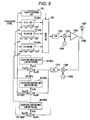
- a compensation operation in a pre-distortion unit 1301 at a previous stage of the transmission amplifier is performed by a power series operation with respect to an input signal x.
- the pre-distortion unit 1301 executes the power series operation with respect to the input signal x, thereby compensating for distortion of a transmission amplifier 1305.
- An output of the pre-distortion unit 1301 is converted into an analog signal in a D/A converter 1302. Further, the output is orthogonally modulated by a signal oscillated by a local oscillator 1304 according to a transmission base station, in an orthogonal modulator 1303.
- the modulated transmission analog signal is power amplified in the transmission amplifier 1305, and an output thereof is supplied to a transmission antenna 1307 through a coupler 1306 and is then transmitted from the transmission antenna.
- the output of the transmission amplifier 1305 is fed back from the coupler 1306 to the input side.
- an output of the coupler 1306 is down converted according to the signal oscillated from the local oscillator 1309 according to the transmission base station, in a down converter 1308. After the output becomes a digital signal by an A/D converter 1310, the output becomes a base band signal in a demodulator.
- an error signal e(n) with a transmission signal Sref(n) that is delayed in a delay circuit is calculated by a subtractor 1311.
- power series operation coefficients a, b, c, and d that are supplied to the pre-distortion unit 1301 are updated by a coefficient updating unit 1312, such that the error signal e(n) is minimized on the basis of a least mean square (LMS) operation.
- LMS least mean square
- the power series operation coefficients are gradually converged to a predetermined value, and a power series operation is performed with respect to the input signal x by the pre-distortion unit 1301 using the power series operation coefficients converged to the predetermined value.
- a nonlinear distortion characteristic of an analog circuit unit is suppressed with high precision while high power efficiency is maintained.
- a variation amount of an analog gain is detected by the feedback signal Sfb(n), and values of the power series operation coefficients are updated by the coefficient updating unit 1312 to compensate for the variation amount. As a result, it is possible to dynamically compensate for the variation in characteristic.
- the above configuration actually has the configuration with respect to a complex signal.
- the nonlinear distortion in the transmission amplifier 1305 may be modeled by a power series, which is composed of only odd-ordered power terms.
- a power series that is operated by the pre-distortion unit 1301 is generally composed of only odd-ordered power terms.
- a distortion compensating apparatus includes a processing circuit that calculates each of a plurality of series operation coefficient pairs based on a transmission signal and a feedback signal of an output from an amplifying circuit performing power amplification of the transmission signal, executes a series operation process with respect to the transmission signal based on the plurality of the series operation coefficient pairs as a distortion compensation of the transmission signal, and inputs a result of the series operation process to the amplifying circuit performing the power amplification, and a selecting unit that, on the basis of power of the transmission signal, selects the series operation process to be executed corresponding to one of the plurality of series operation coefficient pairs, or selects one of the plurality of series operation coefficient pairs to be used in the series operation process to be executed.
- FIG. 1 is a diagram illustrating the configuration of a first embodiment
- FIG. 2 is an operation flowchart illustrating a selection operation of a power series using a selector
- FIG. 3 is a conceptual diagram illustrating a distortion compensation using a plurality of power series (diagram illustrating an example of an amplifier reverse characteristic (gain characteristic) with respect to input power);
- FIG. 4 is a diagram illustrating the configuration of a second embodiment
- FIG. 5 is an operation flowchart of an algorithm of a threshold value determining process that sequentially calculates a threshold value while observing a signal quality
- FIG. 6 is a conceptual diagram illustrating the case where an optimal threshold value is calculated
- FIG. 7 is a diagram illustrating the configuration of a distortion compensating apparatus according to a fourth embodiment.
- FIG. 8 is a diagram illustrating the configuration of a distortion compensating apparatus according to a fifth embodiment
- FIG. 9 is a diagram illustrating the configuration of a distortion compensating apparatus according to a sixth embodiment.
- FIG. 10 is a diagram illustrating an example of a relationship between a frequency distribution and a convergence coefficient of a transmission signal in the case where three power series operation coefficient pairs are used;
- FIG. 11 is a diagram illustrating a principle of a pre-distortion scheme
- FIG. 12 is a diagram illustrating the case where a spectrum characteristic is deteriorated due to a nonlinear characteristic of a transmission amplifier.
- FIG. 13 is a diagram illustrating the configuration of a distortion compensating apparatus according to the related art.
- FIG. 1 is a diagram illustrating the configuration of a first embodiment.
- An aspect of a distortion compensating apparatus according to the first embodiment has the following configuration.
- a series operation processing unit 101 executes a series operation process corresponding to each of a plurality of series operation coefficient pairs with respect to a transmission signal.
- a selector 102 selects one of the plurality of series operation processes in the series operation processing unit on the basis of power of the transmission signal, and inputs the operation result to a circuit performing power amplification.
- a plurality of pre-distortion units (PD units) 101 that perform a power series operation are prepared.
- Each of the PD units 101 executes a different power series operation on the basis of a different power series operation coefficient pair.
- the selector 102 holds (N - 1) power threshold values, sequentially (Step S203 of FIG. 2 ) converts power of a transmission signal by a power converting unit 103 from a minimum threshold value Th(1) (Step S201 of FIG. 2 ) to a maximum threshold value Th(N - 1) (Step S204 of FIG. 2 ), compares (Step S202 of FIG. 2 ) the obtained power signal values with the threshold values Th(i) (1 ⁇ i ⁇ N - 1), and selects the PD unit 101 of #i at a point in time when it is determined that a power signal value is smaller than the threshold values Th(i).
- the PD unit 101 of #N is selected (Step S204 of FIG. 2 ⁇ S206).
- the selector 102 outputs an output of the selected PD unit 101 to a D/A converter at a subsequent stage.
- the configuration of a D/A converter, an orthogonal modulator, a transmission amplifier, and a coupler of a subsequent stage portion of a forward system, and a down converter and an A/D converter of a feedback system are the same as the configuration illustrated in FIG. 13 .
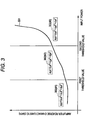
- FIG. 3 is a conceptual diagram illustrating a distortion compensation using a plurality of power series, which illustrates an example of an amplifier reverse characteristic (gain characteristic) with respect to input power.
- An amplifier reverse characteristic 301 that is simulated using a power series illustrates a significantly complex curve in an actual transmission amplifier.
- an error is increased.
- one or more threshold values such as 1 and 2 are set in a (converted) power value of a transmission signal.
- a distortion compensation operation is executed using a different power series 302, such as #1, #2 or #3.
- FIG. 4 is a diagram illustrating the configuration of a second embodiment.
- An aspect of a distortion compensating apparatus according to the second embodiment has the following configuration.
- a series operation coefficient pair storage unit 401 stores each of a plurality of series operation coefficient pairs.
- a selector 402 selects one of the plurality of series operation coefficient pairs from the series operation coefficient pair storage unit on the basis of power of a transmission signal, and executes a series operation process according to the selected series operation coefficient pair.
- the basic operation principle is the same as that of the first embodiment illustrated in FIG. 1 .
- only one pre-distortion unit (PD unit) 404 that performs a power series operation is prepared. Instead, a plurality of coefficient memory units 401 (#1 to #N) that store power series operation coefficient pairs are prepared.
- the PD unit 404 executes a power series operation using a power series operation coefficient pair that is output from the coefficient memory unit 401 selected by the selector 402.
- the selector 402 compares transmission signal power values output from the power converting unit 403 of FIG. 4 with (N - 1) power threshold values Th(i) (1 ⁇ i ⁇ N - 1), selects one of the plurality of coefficient memory units 401 (#1 to #N), and supplies a power series operation coefficient pair, which is output from the selected coefficient memory unit 401, to the PD unit 404.
- the PD unit 404 executes a power series operation using the power series operation coefficient pair that is supplied from the selector 402, and an output thereof is output to a D/A converter at a subsequent stage.
- the configuration of a D/A converter, an orthogonal modulator, a transmission amplifier, and a coupler of a subsequent stage portion of a forward system, and a down converter and an A/D converter of a feedback system are the same as the configuration illustrated in FIG. 13 .
- This embodiment relates to a selection algorithm of a threshold value used when the power series operation is selected (the case of FIG. 1 ) or when the series operation coefficient pair is selected (the case of FIG. 2 ).
- the (N - 1) threshold values Th(i) (1 ⁇ i ⁇ N - 1) that are used when selecting the power series directly affects distortion compensation performance of a pre-distortion process using a power series operation. Accordingly, it is effective to observe various signal qualities and determine the threshold values such that the signal qualities are optimized.
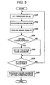
- FIG. 5 An operation flowchart of an algorithm of a threshold value determining process that sequentially calculates threshold values while observing signal qualities is illustrated in FIG. 5 , and a conceptual diagram of the case where an optimal threshold value is calculated is illustrated in FIG. 6 .
- Step S501 After the threshold value is set (Step S501), a waiting state is maintained until the power series operation coefficient pair is converged by an adaptive algorithm and a distortion compensation operation is properly made (Step S502), and a signal quality in the threshold value is obtained (Step S503).
- Step S503 it is determined whether the signal quality that is obtained in Step S503 is an optimal characteristic (Step S504).
- Step S504 ⁇ S506 ⁇ S501.
- Step S501 When the signal quality is the optimal characteristic, the threshold value that is set in Step S501 is set as a threshold value candidate (Step S504 ⁇ S505), and a next threshold value is tried (Step S506 ⁇ S501).
- the currently selected threshold value candidate is output as the optimal threshold value, and the threshold value determining process is completed (Step S506 ⁇ S507).
- the optimal threshold value that is determined in the above way becomes a threshold value that has an optimal signal quality, as illustrated in FIG. 6 .
- This embodiment is a realization example of a scheme that evaluates the signal quality in the third embodiment according to whether the out-of-band distortion is minimized.
- FIG. 7 is a diagram illustrating the configuration of a distortion compensating apparatus according to the fourth embodiment.
- FIG. 7 the portions that are denoted by the same reference numerals as those in the first embodiment of FIG. 1 have the same functions as the portions of FIG. 1 , and the portions that are denoted by the same reference numerals as those in the related art of FIG. 13 have the same functions as the portions of FIG. 13 .
- the distortion compensating apparatus further includes a threshold determining unit (e.g., Optimal Threshold Value Calculating Unit) 702 that determines a threshold value of power in a selecting process, which is executed by the selecting unit on the basis of the power of a transmission signal, on the basis of a signal quality corresponding to at least one of the transmission signal and the feedback signal.
- the distortion compensating apparatus further includes a frequency characteristic (e.g., spectrum) measuring unit 701 that measures a frequency characteristic of the demodulation signal.
- the threshold value determining unit 702 determines a threshold value on the basis of the measurement result of the frequency characteristic measuring unit.
- threshold value determining units 801 or 802 may determine a threshold value on the basis of an error between the demodulation signal and a transmission signal at a previous stage of a circuit performing power amplification, as illustrated in Fig. 8 .
- the spectrum measuring unit 701 acquires a spectrum characteristic of a feedback demodulation signal that is output from an A/D converter 1310, and measures out-of-band distortion power.
- the optimal threshold value calculating unit 702 executes a threshold value determining process on the basis of the operation flowchart of FIG. 5 in the above-described third embodiment.
- the optimal threshold value calculating unit 702 acquires the out-of-band distortion power measured by the spectrum measuring unit 701 as the signal quality.
- the optimal threshold value calculating unit 702 determines whether the out-of-band distortion power is minimized and determines whether the signal quality is an optimal characteristic.
- the optimal threshold value calculating unit 702 sets the threshold value, which is determined by the above process, as a threshold value used to select each of the PD units 101 of #1 to #N. This threshold value is referred to from the selector 102 when the selecting process is executed on the basis of the operation flowchart illustrated in FIG. 2 .
- the out-of-band distortion may be calculated by acquiring the spectrum characteristic.
- the optimal threshold value may be calculated by using the algorithm of FIG. 5 .
- the configuration of the fourth embodiment illustrated in FIG. 7 is based on the configuration of the first embodiment illustrated in FIG. 1 . However, even if the configuration of the fourth embodiment were based on the configuration of the second embodiment illustrated in FIG. 4 , the same effect may be obtained.
- This embodiment is a realization example of a scheme that evaluates the signal quality in the third embodiment according to whether the distortion is totally minimized, as described above.
- FIG. 8 is a diagram illustrating the configuration of a distortion compensating apparatus according to a fifth embodiment.
- FIG. 8 the portions that are denoted by the same reference numerals as those in the first embodiment of FIG. 1 have the same functions as the portions of FIG. 1 , and the portions that are denoted by the same reference numerals as those in the related art of FIG. 13 have the same functions as the portions of FIG. 13 .
- the distortion compensating apparatus further includes a threshold value determining unit (e.g., Optimal Threshold Value Calculating Unit) 802 that determines a threshold value of power in a selecting process, which is executed by the selecting unit on the basis of the power of a transmission signal, on the basis of a signal quality corresponding to at least one of the transmission signal and the feedback signal.
- a threshold value determining unit 801 or 802 determines a threshold value on the basis of an error between the demodulation signal and a transmission signal at a previous stage of a circuit performing power amplification.
- an error signal e(n) that is obtained by subtracting a feedback signal Sfb(n) from a delay transmission signal Sref(n) by a subtractor 1311 may be used as an index.
- the error averaging unit 801 calculates an average value with respect to the error signal e(n) that is obtained by subtracting the feedback signal Sfb(n) from the delay transmission signal Sref(n) by the subtractor 1311, for each predetermined interval.
- the optimal threshold value calculating unit 802 executes the threshold value determining process on the basis of the operation flowchart of FIG. 5 in the above-described third embodiment.
- the optimal threshold value calculating unit 802 acquires the error average value calculated by the error averaging unit 801 as the signal quality.
- the optimal threshold value calculating unit 802 determines whether the error average value is minimized and determines whether the signal quality is an optimal characteristic.
- the optimal threshold value calculating unit 802 sets the threshold value, which is determined by the above process, as a threshold value used to select each of the PD units 101 of #1 to #N. This threshold value is referred to from the selector 102 when the selecting process is executed on the basis of the operation flowchart illustrated in FIG. 2 .
- the error signal e(n) may be replaced by a characteristic called modulation precision or EVM (Error Vector Magnitude).
- EVM Error Vector Magnitude
- EVM % ⁇ i
- the configuration of the fifth embodiment illustrated in FIG. 8 is based on the configuration of the first embodiment illustrated in FIG. 1 . However, even if the configuration of the fifth embodiment were based on the configuration of the second embodiment illustrated in FIG. 4 , the same effect can be obtained.
- This embodiment relates to an adaptive update algorithm of a power series operation coefficient pair.
- FIG. 9 is a diagram illustrating the configuration of a distortion compensating apparatus according to a sixth embodiment.
- FIG. 9 the portions that are denoted by the same reference numerals as those in the first embodiment of FIG. 1 have the same functions as the portions of FIG. 1 , and the portions that are denoted by the same reference numerals as those in the related art of FIG. 13 have the same functions as the portions of FIG. 13 .
- the distortion compensating apparatus further includes a series operation coefficient pair updating unit 901 that converges each of a plurality of series operation coefficient pairs using an adaptive algorithm such that an error between a demodulation signal and a transmission signal at a previous stage of a circuit performing power amplification is minimized.
- the series operation coefficient pair updating unit 901 determines a convergence coefficient in the adaptive algorithm with respect to each of the plurality of series operation coefficient pairs in accordance with a signal frequency distribution for every power range to which each pair corresponds.
- the series operation coefficient pair updating unit 901 may determine a convergence coefficient in the adaptive algorithm with respect to each of the plurality of series operation coefficient pairs in accordance with signal power for every power range to which each pair corresponds.
- the coefficient updating units 901 of #1 to #N in order to adaptively associate the individual distortion compensation characteristics of the PD units 101 of #1 to #N with a variation in amplification characteristic due to an individual difference of the transmission amplifier 1305 and a variation in amplification characteristic due to a secular change and a temperature change, in the coefficient updating units 901 of #1 to #N, the power series operation coefficient pairs of #1 to #N are updated on the basis of the error signal e(n) output from corresponding subtractors 1311 of #1 to #N, such that each error signal e(n) is minimized on the basis of a least mean square operation.
- an adaptive algorithm that has a small operation amount and that easily adjusts to a temporal variation is generally used.
- the plurality of power series operation coefficient pairs are used, it is effective to properly apply the adaptive algorithm with respect to each of the plurality of power series operation coefficient pairs and converge the coefficient pairs.
- the plurality of power series operation coefficient pairs are used.
- a convergence speed and stability of each power series operation coefficient pair are varied and optimized, thereby optimizing the stability and the convergence speed of the distortion compensation performance. Accordingly, it is effective to vary the convergence coefficient for each power series operation coefficient pair.
- a scheme where the convergence coefficient is determined in accordance with a frequency distribution of a signal for every power range corresponding to each power series is considered.
- An example of a relationship between a convergence coefficient and a frequency distribution of a transmission signal in the case where three power series operation coefficient pairs are used is illustrated in FIG. 10 .
- the convergence coefficient that corresponds to each power series operation coefficient pair is determined to be in inverse proportion to a signal frequency of a range of each power series. In order to achieve sufficient distortion compensation performance, all of the power series operation coefficient pairs need to be converged.
- ⁇ having a large value is used. As a result, a convergence speed of the corresponding portion is increased, and a convergence time may be shortened.
- Equation 3 a smaller ⁇ is used for a larger power portion, and the coefficient updating portion of Equation 3 may be constantly approximated. In this way, the convergence performance and the stability performance of the three power series may be achieved, and superior distortion compensation performance may be obtained.
- the threshold value is set to the transmission power and the pre-distortion is performed using the plurality of power series. Therefore, superior distortion compensation performance may be obtained as compared with the case of using a single power series.
- first to sixth embodiments have been described on the basis of the power series model, but the present invention is not limited thereto.
- the first to sixth embodiments may be applied to various series models.
Landscapes
- Physics & Mathematics (AREA)
- Nonlinear Science (AREA)
- Engineering & Computer Science (AREA)
- Power Engineering (AREA)
- Algebra (AREA)
- General Physics & Mathematics (AREA)
- Mathematical Analysis (AREA)
- Mathematical Optimization (AREA)
- Pure & Applied Mathematics (AREA)
- Amplifiers (AREA)
- Transmitters (AREA)
Claims (15)
- Verzerrungskompensationsvorrichtung, umfassend:eine Verarbeitungsschaltung (702, 802), die angeordnet ist, um jedes von einer Vielzahl von Serienoperationskoeffizientenpaaren basierend auf einem Sendesignal und einem Rückführungssignal einer Ausgabe von einer Verstärkungsschaltung zu berechnen, die eine Leistungsverstärkung des Sendesignals ausführt, einen Serienoperationsprozess bezüglich des Sendesignals basierend auf der Vielzahl der Serienoperationskoeffizientenpaare als Verzerrungskompensation des Sendesignals durchzuführen und ein Resultat des Serienoperationsprozesses der Verstärkungsschaltung einzugeben, die die Leistungsverstärkung ausführt; undeine Selektionseinheit (102, 402), die angeordnet ist, um auf der Basis der Leistung des Sendesignals den durchzuführenden Serienoperationsprozess (101) zu selektieren, der einem von der Vielzahl von Serienoperationskoeffizientenpaaren entspricht, oder eines von der Vielzahl von Serienoperationskoeffizientenpaaren (401) zu selektieren, das bei dem durchzuführenden Serienoperationsprozess zu verwenden ist.
- Verzerrungskompensationsvorrichtung nach Anspruch 1, bei der
die Verarbeitungseinheit eine Vielzahl von Serienoperationsverarbeitungseinheiten (101) umfasst, von denen jede angeordnet ist, um den Serienoperationsprozess entsprechend jedem von der Vielzahl von Serienoperationskoeffizientenpaaren bezüglich des Sendesignals durchzuführen, und
die Selektionseinheit (102) angeordnet ist, um als durchzuführenden Serienoperationsprozess den Serienoperationsprozess in einer von der Vielzahl der Serienoperationsverarbeitungseinheiten entsprechend dem einen von der Vielzahl von Serienoperationskoeffizientenpaaren zu selektieren. - Verzerrungskompensationsvorrichtung nach Anspruch 1, bei der
die Verarbeitungseinheit einen Serienoperationskoeffizientenpaarspeicher (401) zum Speichern eines jeden von der Vielzahl von Serienoperationskoeffizientenpaaren umfasst und
die Selektionseinheit (402) angeordnet ist, um das eine von der Vielzahl von Serienoperationskoeffizientenpaaren von dem Serienoperationskoeffizientenpaarspeicher zu selektieren, das bei dem durchzuführenden Serienoperationsprozess zu verwenden ist. - Verzerrungskompensationsvorrichtung nach einem der Ansprüche 1 bis 3, ferner umfassend:eine Schwellenwertbestimmungseinheit, die angeordnet ist, um einen Schwellenwert der Leistung bei dem Selektionsprozess, der durch die Selektionseinheit basierend auf der Leistung des Sendesignals durchzuführen ist, auf der Basis einer Signalgüte entsprechend wenigstens einem von dem Sendesignal und dem Rückführungssignal zu bestimmen.
- Verzerrungskompensationsvorrichtung nach Anspruch 4, ferner umfassend:eine Frequenzcharakteristikmesseinheit, die angeordnet ist, um eine Frequenzcharakteristik des Rückführungssignals zu messen,bei der die Schwellenwertbestimmungseinheit angeordnet ist, um den Schwellenwert auf der Basis des Messresultates der Frequenzcharakteristikmesseinheit zu bestimmen.
- Verzerrungskompensationsvorrichtung nach Anspruch 4,
bei der die Schwellenwertbestimmungseinheit angeordnet ist, um den Schwellenwert auf der Basis eines Fehlers zwischen dem Rückführungssignal und dem Sendesignal zu bestimmen. - Verzerrungskompensationsvorrichtung nach einem der Ansprüche 1 bis 6, ferner umfassend:eine Serienoperationskoeffizientenpaaraktualisierungseinheit (1312) zum Konvergieren jedes von der Vielzahl von Serienoperationskoeffizientenpaaren unter Verwendung eines adaptiven Algorithmus, so dass ein Fehler zwischen dem Rückführungssignal und dem Sendesignal einer gegebenen Bedingung genügt.
- Verzerrungskompensationsvorrichtung nach Anspruch 7,
bei der die Serienoperationskoeffizientenpaaraktualisierungseinheit angeordnet ist, um einen Konvergenzkoeffizienten bei dem adaptiven Algorithmus gemäß einer Signalfrequenzverteilung für jeden Leistungsbereich entsprechend jedem von der Vielzahl von Serienoperationskoeffizientenpaaren bezüglich jedes Paares zu bestimmen. - Verzerrungskompensationsvorrichtung nach Anspruch 7,
bei der die Serienoperationskoeffizientenpaaraktualisierungseinheit angeordnet ist, um einen Konvergenzkoeffizienten bei dem adaptiven Algorithmus gemäß der Signalleistung für jeden Leistungsbereich entsprechend jedem von der Vielzahl von Serienoperationskoeffizientenpaaren bezüglich jedes Paares zu bestimmen. - Verzerrungskompensationsvorrichtung nach einem der Ansprüche 1 bis 9,
bei der der Serienoperationsprozess ein Leistungsserienoperationsprozess ist. - Verzerrungskompensationsverfahren, umfassend:Berechnen eines jeden von einer Vielzahl von Serienoperationskoeffizientenpaaren basierend auf einem Sendesignal und einem Rückführungssignal einer Ausgabe von einer Schaltung, die eine Leistungsverstärkung des Sendesignals ausführt;Durchführen eines Serienoperationsprozesses bezüglich des Sendesignals basierend auf der Vielzahl von Serienoperationskoeffizientenpaaren als Verzerrungskompensation des Sendesignals;Eingeben des Serienoperationsresultates in die Schaltung, die die Leistungsverstärkung ausführt; undSelektieren, auf der Basis der Leistung des Sendesignals, des durchzuführenden Serienoperationsprozesses, der einem von der Vielzahl von Serienoperationskoeffizientenpaaren entspricht, oder eines von der Vielzahl von Serienoperationskoeffizientenpaaren, das bei dem durchzuführenden Serienoperationsprozess zu verwenden ist.
- Verzerrungskompensationsverfahren nach Anspruch 11, bei dem
das Durchführen die Durchführung eines jeden von einer Vielzahl von Serienoperationsprozessen entsprechend einem von der Vielzahl von Serienoperationskoeffizientenpaaren bezüglich des Sendesignals enthält; und
das Selektieren die Selektion eines von der Vielzahl von Serienoperationsprozessen als durchzuführenden Serienoperationsprozess enthält, der dem einen von der Vielzahl der Serienoperationskoeffizientenpaare entspricht. - Verzerrungskompensationsverfahren nach Anspruch 11, bei dem
das Durchführen das Speichern eines jeden von der Vielzahl von Serienoperationskoeffizientenpaaren in einem Serienoperationskoeffizientenpaarspeicher enthält und
die Selektionseinheit das eine von der Vielzahl von Serienoperationskoeffizientenpaaren von dem Serienoperationskoeffizientenpaarspeicher selektiert, um bei dem durchzuführenden Serienoperationsprozess verwendet zu werden. - Verzerrungskompensationsverfahren nach einem der Ansprüche 11 bis 13,
bei dem ein Schwellenwert der Sendeleistung, der bei der Selektion basierend auf der Leistung des Sendesignals verwendet wird, auf der Basis einer Signalgüte entsprechend wenigstens einem von dem Sendesignal und dem Rückführungssignal bestimmt wird. - Verzerrungskompensationsverfahren nach einem der Ansprüche 11 bis 14,
bei dem jedes von der Vielzahl von Serienoperationskoeffizientenpaaren unter Verwendung eines adaptiven Algorithmus konvergiert wird, so dass ein Fehler zwischen dem Rückführungssignal und dem Sendesignal einer gegebenen Bedingung genügt, und jedes von der Vielzahl von Serienoperationskoeffizientenpaaren aktualisiert wird.
Applications Claiming Priority (1)
| Application Number | Priority Date | Filing Date | Title |
|---|---|---|---|
| JP2008232294A JP5228723B2 (ja) | 2008-09-10 | 2008-09-10 | 歪補償装置及び方法 |
Publications (2)
| Publication Number | Publication Date |
|---|---|
| EP2164172A1 EP2164172A1 (de) | 2010-03-17 |
| EP2164172B1 true EP2164172B1 (de) | 2012-11-28 |
Family
ID=41412440
Family Applications (1)
| Application Number | Title | Priority Date | Filing Date |
|---|---|---|---|
| EP09169620A Not-in-force EP2164172B1 (de) | 2008-09-10 | 2009-09-07 | Vorrichtung und Verfahren zur Verzerrungskompensation |
Country Status (3)
| Country | Link |
|---|---|
| US (1) | US8270530B2 (de) |
| EP (1) | EP2164172B1 (de) |
| JP (1) | JP5228723B2 (de) |
Families Citing this family (4)
| Publication number | Priority date | Publication date | Assignee | Title |
|---|---|---|---|---|
| JP5071370B2 (ja) * | 2008-12-26 | 2012-11-14 | 富士通株式会社 | 歪補償装置及び方法 |
| US8565343B1 (en) * | 2010-06-29 | 2013-10-22 | Qualcomm Incorporated | Transmit power control utilizing loopback error vector magnitude thresholds |
| JP5753272B2 (ja) * | 2010-11-16 | 2015-07-22 | テレフオンアクチーボラゲット エル エム エリクソン(パブル) | タップ出力の正規化を伴う非線形モデル |
| US10985951B2 (en) | 2019-03-15 | 2021-04-20 | The Research Foundation for the State University | Integrating Volterra series model and deep neural networks to equalize nonlinear power amplifiers |
Family Cites Families (14)
| Publication number | Priority date | Publication date | Assignee | Title |
|---|---|---|---|---|
| JP3323715B2 (ja) * | 1995-11-30 | 2002-09-09 | 富士通株式会社 | 無線装置 |
| JP3171157B2 (ja) * | 1997-12-10 | 2001-05-28 | 松下電器産業株式会社 | 非線形歪補償装置 |
| WO2000074232A1 (en) * | 1999-05-28 | 2000-12-07 | Fujitsu Limited | Predistortion type distortion compensation amplifier |
| US6356146B1 (en) * | 1999-07-13 | 2002-03-12 | Pmc-Sierra, Inc. | Amplifier measurement and modeling processes for use in generating predistortion parameters |
| JP4183364B2 (ja) * | 1999-12-28 | 2008-11-19 | 富士通株式会社 | 歪補償装置 |
| JP2001268150A (ja) | 2000-03-21 | 2001-09-28 | Hitachi Kokusai Electric Inc | リニアライザ |
| JP4281260B2 (ja) | 2001-05-07 | 2009-06-17 | 三菱電機株式会社 | Fm復調器および受信機 |
| US7030693B2 (en) * | 2003-04-30 | 2006-04-18 | Lucent Technologies Inc. | Enhanced predistortion method and apparatus |
| JP4255849B2 (ja) * | 2004-01-29 | 2009-04-15 | 株式会社エヌ・ティ・ティ・ドコモ | べき級数型ディジタルプリディストータ |
| JP4576221B2 (ja) | 2004-02-03 | 2010-11-04 | 株式会社エヌ・ティ・ティ・ドコモ | 多周波帯用べき級数型プリディストータ |
| US7170344B2 (en) * | 2004-02-03 | 2007-01-30 | Ntt Docomo, Inc. | Multi-band predistorter using power series representation |
| US7551686B1 (en) * | 2004-06-23 | 2009-06-23 | Rf Micro Devices, Inc. | Multiple polynomial digital predistortion |
| US7514996B2 (en) * | 2004-09-21 | 2009-04-07 | Hitachi Kokusai Electric Inc. | Distortion compensation amplifying apparatus |
| US7288988B2 (en) * | 2005-04-13 | 2007-10-30 | Powerwave Technologies, Inc. | Adaptive predistortion linearized amplifier system employing selective sampling |
-
2008
- 2008-09-10 JP JP2008232294A patent/JP5228723B2/ja not_active Expired - Fee Related
-
2009
- 2009-09-07 EP EP09169620A patent/EP2164172B1/de not_active Not-in-force
- 2009-09-08 US US12/555,314 patent/US8270530B2/en not_active Expired - Fee Related
Also Published As
| Publication number | Publication date |
|---|---|
| US20100060355A1 (en) | 2010-03-11 |
| US8270530B2 (en) | 2012-09-18 |
| JP2010068217A (ja) | 2010-03-25 |
| JP5228723B2 (ja) | 2013-07-03 |
| EP2164172A1 (de) | 2010-03-17 |
Similar Documents
| Publication | Publication Date | Title |
|---|---|---|
| KR101067099B1 (ko) | 왜곡 보상 장치 및 방법 | |
| US7418056B2 (en) | Digital predistorter using power series model | |
| US20150214904A1 (en) | Distortion compensation apparatus and distortion compensation method | |
| US8737937B2 (en) | Distortion compensation apparatus, transmitter, and distortion compensation method | |
| US10797737B2 (en) | Distortion compensation device and distortion compensation method | |
| EP2202878A1 (de) | Verzerrungsausgleichsverfahren und -vorrichtung | |
| US9444412B2 (en) | Distortion compensation apparatus and method therefor | |
| US20110187455A1 (en) | Adaptive Digital Predistortion Device and Method | |
| EP2164172B1 (de) | Vorrichtung und Verfahren zur Verzerrungskompensation | |
| US8712345B2 (en) | Distortion compensation device, distortion compensation method, and radio transmitter | |
| JP5593724B2 (ja) | 増幅装置とこれを備えた無線送信装置、及び、増幅装置の利得調整方法 | |
| KR101129143B1 (ko) | 왜곡 보상 장치 및 방법 | |
| US20180013456A1 (en) | Distortion compensation device and distortion compensation method | |
| JP5316325B2 (ja) | 歪補償回路、及びこれを用いた無線送信装置、歪補償方法 | |
| US9590827B2 (en) | Distortion compensation apparatus, wireless communication system, and distortion compensation method | |
| US9270260B2 (en) | Distortion compensation device | |
| KR101683457B1 (ko) | 포화 영역을 고려하는 디지털 전치왜곡 전력 증폭 장치 및 방법 | |
| WO2011058803A1 (ja) | 歪補償回路 |
Legal Events
| Date | Code | Title | Description |
|---|---|---|---|
| PUAI | Public reference made under article 153(3) epc to a published international application that has entered the european phase |
Free format text: ORIGINAL CODE: 0009012 |
|
| AK | Designated contracting states |
Kind code of ref document: A1 Designated state(s): AT BE BG CH CY CZ DE DK EE ES FI FR GB GR HR HU IE IS IT LI LT LU LV MC MK MT NL NO PL PT RO SE SI SK SM TR |
|
| AX | Request for extension of the european patent |
Extension state: AL BA RS |
|
| 17P | Request for examination filed |
Effective date: 20100913 |
|
| GRAP | Despatch of communication of intention to grant a patent |
Free format text: ORIGINAL CODE: EPIDOSNIGR1 |
|
| GRAS | Grant fee paid |
Free format text: ORIGINAL CODE: EPIDOSNIGR3 |
|
| GRAA | (expected) grant |
Free format text: ORIGINAL CODE: 0009210 |
|
| AK | Designated contracting states |
Kind code of ref document: B1 Designated state(s): AT BE BG CH CY CZ DE DK EE ES FI FR GB GR HR HU IE IS IT LI LT LU LV MC MK MT NL NO PL PT RO SE SI SK SM TR |
|
| REG | Reference to a national code |
Ref country code: GB Ref legal event code: FG4D |
|
| REG | Reference to a national code |
Ref country code: CH Ref legal event code: EP |
|
| REG | Reference to a national code |
Ref country code: AT Ref legal event code: REF Ref document number: 586614 Country of ref document: AT Kind code of ref document: T Effective date: 20121215 |
|
| REG | Reference to a national code |
Ref country code: IE Ref legal event code: FG4D |
|
| REG | Reference to a national code |
Ref country code: DE Ref legal event code: R096 Ref document number: 602009011490 Country of ref document: DE Effective date: 20130124 |
|
| REG | Reference to a national code |
Ref country code: AT Ref legal event code: MK05 Ref document number: 586614 Country of ref document: AT Kind code of ref document: T Effective date: 20121128 |
|
| REG | Reference to a national code |
Ref country code: NL Ref legal event code: VDEP Effective date: 20121128 |
|
| REG | Reference to a national code |
Ref country code: LT Ref legal event code: MG4D |
|
| PG25 | Lapsed in a contracting state [announced via postgrant information from national office to epo] |
Ref country code: LT Free format text: LAPSE BECAUSE OF FAILURE TO SUBMIT A TRANSLATION OF THE DESCRIPTION OR TO PAY THE FEE WITHIN THE PRESCRIBED TIME-LIMIT Effective date: 20121128 Ref country code: NO Free format text: LAPSE BECAUSE OF FAILURE TO SUBMIT A TRANSLATION OF THE DESCRIPTION OR TO PAY THE FEE WITHIN THE PRESCRIBED TIME-LIMIT Effective date: 20130228 Ref country code: HR Free format text: LAPSE BECAUSE OF FAILURE TO SUBMIT A TRANSLATION OF THE DESCRIPTION OR TO PAY THE FEE WITHIN THE PRESCRIBED TIME-LIMIT Effective date: 20121128 Ref country code: FI Free format text: LAPSE BECAUSE OF FAILURE TO SUBMIT A TRANSLATION OF THE DESCRIPTION OR TO PAY THE FEE WITHIN THE PRESCRIBED TIME-LIMIT Effective date: 20121128 Ref country code: SE Free format text: LAPSE BECAUSE OF FAILURE TO SUBMIT A TRANSLATION OF THE DESCRIPTION OR TO PAY THE FEE WITHIN THE PRESCRIBED TIME-LIMIT Effective date: 20121128 Ref country code: ES Free format text: LAPSE BECAUSE OF FAILURE TO SUBMIT A TRANSLATION OF THE DESCRIPTION OR TO PAY THE FEE WITHIN THE PRESCRIBED TIME-LIMIT Effective date: 20130311 |
|
| PG25 | Lapsed in a contracting state [announced via postgrant information from national office to epo] |
Ref country code: PL Free format text: LAPSE BECAUSE OF FAILURE TO SUBMIT A TRANSLATION OF THE DESCRIPTION OR TO PAY THE FEE WITHIN THE PRESCRIBED TIME-LIMIT Effective date: 20121128 Ref country code: PT Free format text: LAPSE BECAUSE OF FAILURE TO SUBMIT A TRANSLATION OF THE DESCRIPTION OR TO PAY THE FEE WITHIN THE PRESCRIBED TIME-LIMIT Effective date: 20130328 Ref country code: LV Free format text: LAPSE BECAUSE OF FAILURE TO SUBMIT A TRANSLATION OF THE DESCRIPTION OR TO PAY THE FEE WITHIN THE PRESCRIBED TIME-LIMIT Effective date: 20121128 Ref country code: SI Free format text: LAPSE BECAUSE OF FAILURE TO SUBMIT A TRANSLATION OF THE DESCRIPTION OR TO PAY THE FEE WITHIN THE PRESCRIBED TIME-LIMIT Effective date: 20121128 Ref country code: GR Free format text: LAPSE BECAUSE OF FAILURE TO SUBMIT A TRANSLATION OF THE DESCRIPTION OR TO PAY THE FEE WITHIN THE PRESCRIBED TIME-LIMIT Effective date: 20130301 Ref country code: BE Free format text: LAPSE BECAUSE OF FAILURE TO SUBMIT A TRANSLATION OF THE DESCRIPTION OR TO PAY THE FEE WITHIN THE PRESCRIBED TIME-LIMIT Effective date: 20121128 |
|
| PG25 | Lapsed in a contracting state [announced via postgrant information from national office to epo] |
Ref country code: AT Free format text: LAPSE BECAUSE OF FAILURE TO SUBMIT A TRANSLATION OF THE DESCRIPTION OR TO PAY THE FEE WITHIN THE PRESCRIBED TIME-LIMIT Effective date: 20121128 |
|
| PG25 | Lapsed in a contracting state [announced via postgrant information from national office to epo] |
Ref country code: CZ Free format text: LAPSE BECAUSE OF FAILURE TO SUBMIT A TRANSLATION OF THE DESCRIPTION OR TO PAY THE FEE WITHIN THE PRESCRIBED TIME-LIMIT Effective date: 20121128 Ref country code: SK Free format text: LAPSE BECAUSE OF FAILURE TO SUBMIT A TRANSLATION OF THE DESCRIPTION OR TO PAY THE FEE WITHIN THE PRESCRIBED TIME-LIMIT Effective date: 20121128 Ref country code: BG Free format text: LAPSE BECAUSE OF FAILURE TO SUBMIT A TRANSLATION OF THE DESCRIPTION OR TO PAY THE FEE WITHIN THE PRESCRIBED TIME-LIMIT Effective date: 20130228 Ref country code: EE Free format text: LAPSE BECAUSE OF FAILURE TO SUBMIT A TRANSLATION OF THE DESCRIPTION OR TO PAY THE FEE WITHIN THE PRESCRIBED TIME-LIMIT Effective date: 20121128 Ref country code: DK Free format text: LAPSE BECAUSE OF FAILURE TO SUBMIT A TRANSLATION OF THE DESCRIPTION OR TO PAY THE FEE WITHIN THE PRESCRIBED TIME-LIMIT Effective date: 20121128 |
|
| PG25 | Lapsed in a contracting state [announced via postgrant information from national office to epo] |
Ref country code: RO Free format text: LAPSE BECAUSE OF FAILURE TO SUBMIT A TRANSLATION OF THE DESCRIPTION OR TO PAY THE FEE WITHIN THE PRESCRIBED TIME-LIMIT Effective date: 20121128 Ref country code: NL Free format text: LAPSE BECAUSE OF FAILURE TO SUBMIT A TRANSLATION OF THE DESCRIPTION OR TO PAY THE FEE WITHIN THE PRESCRIBED TIME-LIMIT Effective date: 20121128 Ref country code: IT Free format text: LAPSE BECAUSE OF FAILURE TO SUBMIT A TRANSLATION OF THE DESCRIPTION OR TO PAY THE FEE WITHIN THE PRESCRIBED TIME-LIMIT Effective date: 20121128 |
|
| PLBE | No opposition filed within time limit |
Free format text: ORIGINAL CODE: 0009261 |
|
| STAA | Information on the status of an ep patent application or granted ep patent |
Free format text: STATUS: NO OPPOSITION FILED WITHIN TIME LIMIT |
|
| 26N | No opposition filed |
Effective date: 20130829 |
|
| PG25 | Lapsed in a contracting state [announced via postgrant information from national office to epo] |
Ref country code: CY Free format text: LAPSE BECAUSE OF FAILURE TO SUBMIT A TRANSLATION OF THE DESCRIPTION OR TO PAY THE FEE WITHIN THE PRESCRIBED TIME-LIMIT Effective date: 20121128 |
|
| REG | Reference to a national code |
Ref country code: DE Ref legal event code: R097 Ref document number: 602009011490 Country of ref document: DE Effective date: 20130829 |
|
| PG25 | Lapsed in a contracting state [announced via postgrant information from national office to epo] |
Ref country code: MC Free format text: LAPSE BECAUSE OF FAILURE TO SUBMIT A TRANSLATION OF THE DESCRIPTION OR TO PAY THE FEE WITHIN THE PRESCRIBED TIME-LIMIT Effective date: 20121128 |
|
| REG | Reference to a national code |
Ref country code: CH Ref legal event code: PL |
|
| REG | Reference to a national code |
Ref country code: IE Ref legal event code: MM4A |
|
| PG25 | Lapsed in a contracting state [announced via postgrant information from national office to epo] |
Ref country code: CH Free format text: LAPSE BECAUSE OF NON-PAYMENT OF DUE FEES Effective date: 20130930 Ref country code: LI Free format text: LAPSE BECAUSE OF NON-PAYMENT OF DUE FEES Effective date: 20130930 Ref country code: IE Free format text: LAPSE BECAUSE OF NON-PAYMENT OF DUE FEES Effective date: 20130907 |
|
| PG25 | Lapsed in a contracting state [announced via postgrant information from national office to epo] |
Ref country code: SM Free format text: LAPSE BECAUSE OF FAILURE TO SUBMIT A TRANSLATION OF THE DESCRIPTION OR TO PAY THE FEE WITHIN THE PRESCRIBED TIME-LIMIT Effective date: 20121128 |
|
| PG25 | Lapsed in a contracting state [announced via postgrant information from national office to epo] |
Ref country code: MT Free format text: LAPSE BECAUSE OF FAILURE TO SUBMIT A TRANSLATION OF THE DESCRIPTION OR TO PAY THE FEE WITHIN THE PRESCRIBED TIME-LIMIT Effective date: 20121128 Ref country code: TR Free format text: LAPSE BECAUSE OF FAILURE TO SUBMIT A TRANSLATION OF THE DESCRIPTION OR TO PAY THE FEE WITHIN THE PRESCRIBED TIME-LIMIT Effective date: 20121128 |
|
| PG25 | Lapsed in a contracting state [announced via postgrant information from national office to epo] |
Ref country code: HU Free format text: LAPSE BECAUSE OF FAILURE TO SUBMIT A TRANSLATION OF THE DESCRIPTION OR TO PAY THE FEE WITHIN THE PRESCRIBED TIME-LIMIT; INVALID AB INITIO Effective date: 20090907 Ref country code: MK Free format text: LAPSE BECAUSE OF FAILURE TO SUBMIT A TRANSLATION OF THE DESCRIPTION OR TO PAY THE FEE WITHIN THE PRESCRIBED TIME-LIMIT Effective date: 20121128 Ref country code: LU Free format text: LAPSE BECAUSE OF NON-PAYMENT OF DUE FEES Effective date: 20130907 |
|
| PG25 | Lapsed in a contracting state [announced via postgrant information from national office to epo] |
Ref country code: IS Free format text: LAPSE BECAUSE OF FAILURE TO SUBMIT A TRANSLATION OF THE DESCRIPTION OR TO PAY THE FEE WITHIN THE PRESCRIBED TIME-LIMIT Effective date: 20121128 |
|
| REG | Reference to a national code |
Ref country code: FR Ref legal event code: PLFP Year of fee payment: 8 |
|
| REG | Reference to a national code |
Ref country code: FR Ref legal event code: PLFP Year of fee payment: 9 |
|
| PGFP | Annual fee paid to national office [announced via postgrant information from national office to epo] |
Ref country code: GB Payment date: 20170906 Year of fee payment: 9 Ref country code: FR Payment date: 20170810 Year of fee payment: 9 Ref country code: DE Payment date: 20170830 Year of fee payment: 9 |
|
| REG | Reference to a national code |
Ref country code: DE Ref legal event code: R119 Ref document number: 602009011490 Country of ref document: DE |
|
| GBPC | Gb: european patent ceased through non-payment of renewal fee |
Effective date: 20180907 |
|
| PG25 | Lapsed in a contracting state [announced via postgrant information from national office to epo] |
Ref country code: DE Free format text: LAPSE BECAUSE OF NON-PAYMENT OF DUE FEES Effective date: 20190402 |
|
| PG25 | Lapsed in a contracting state [announced via postgrant information from national office to epo] |
Ref country code: FR Free format text: LAPSE BECAUSE OF NON-PAYMENT OF DUE FEES Effective date: 20180930 |
|
| PG25 | Lapsed in a contracting state [announced via postgrant information from national office to epo] |
Ref country code: GB Free format text: LAPSE BECAUSE OF NON-PAYMENT OF DUE FEES Effective date: 20180907 |