EP2163781A1 - Federanordnung - Google Patents
Federanordnung Download PDFInfo
- Publication number
- EP2163781A1 EP2163781A1 EP09009593A EP09009593A EP2163781A1 EP 2163781 A1 EP2163781 A1 EP 2163781A1 EP 09009593 A EP09009593 A EP 09009593A EP 09009593 A EP09009593 A EP 09009593A EP 2163781 A1 EP2163781 A1 EP 2163781A1
- Authority
- EP
- European Patent Office
- Prior art keywords
- spring element
- spring
- arrangement according
- spring arrangement
- adjusting device
- Prior art date
- Legal status (The legal status is an assumption and is not a legal conclusion. Google has not performed a legal analysis and makes no representation as to the accuracy of the status listed.)
- Granted
Links
- 230000004323 axial length Effects 0.000 claims abstract description 7
- 239000012530 fluid Substances 0.000 claims description 5
- 239000007788 liquid Substances 0.000 claims description 3
- 239000013536 elastomeric material Substances 0.000 claims description 2
- 230000036316 preload Effects 0.000 description 2
- 230000000750 progressive effect Effects 0.000 description 2
- 238000005299 abrasion Methods 0.000 description 1
- 230000001133 acceleration Effects 0.000 description 1
- 230000000712 assembly Effects 0.000 description 1
- 238000000429 assembly Methods 0.000 description 1
- 230000005540 biological transmission Effects 0.000 description 1
- 230000006835 compression Effects 0.000 description 1
- 238000007906 compression Methods 0.000 description 1
- 230000001419 dependent effect Effects 0.000 description 1
- 229920001971 elastomer Polymers 0.000 description 1
- 239000000806 elastomer Substances 0.000 description 1
- 210000003746 feather Anatomy 0.000 description 1
- 230000035939 shock Effects 0.000 description 1
- 239000000725 suspension Substances 0.000 description 1
Images
Classifications
-
- F—MECHANICAL ENGINEERING; LIGHTING; HEATING; WEAPONS; BLASTING
- F16—ENGINEERING ELEMENTS AND UNITS; GENERAL MEASURES FOR PRODUCING AND MAINTAINING EFFECTIVE FUNCTIONING OF MACHINES OR INSTALLATIONS; THERMAL INSULATION IN GENERAL
- F16F—SPRINGS; SHOCK-ABSORBERS; MEANS FOR DAMPING VIBRATION
- F16F1/00—Springs
- F16F1/36—Springs made of rubber or other material having high internal friction, e.g. thermoplastic elastomers
- F16F1/3615—Springs made of rubber or other material having high internal friction, e.g. thermoplastic elastomers with means for modifying the spring characteristic
Definitions
- the invention relates to a spring arrangement according to claim 1.
- Feathers are known to be characterized by their spring constant and their characteristic. A distinction is made between tension, compression and torsion springs with linear, progressive and degressive spring characteristics.
- Spring assemblies are often used in chassis of vehicles, including in industrial trucks to mitigate the transmission of shock to the wheels on the chassis and / or to ensure good lateral stability when cornering. It is known to bias the suspension springs depending on operating parameters. If above and below of operating parameters is mentioned, in addition to the load, for example, steering angle, acceleration / deceleration, inclination angle, load height, vehicle side inclination, etc. meant. The working area thus shifts along the spring characteristic. In linear springs, the spring characteristic remains constant in each work area, with progressive and degressive springs, however, the spring characteristic changes depending on the position of the work area on the spring characteristic and thus the dependence of the spring preload introduced. In a chassis with support rollers (truck) means an increase the support roller load a reduction of the drive wheel load, which is undesirable.
- the object of the invention is to provide a spring arrangement in which, depending on an operating parameter, the spring characteristic can be changed, in particular without varying the spring biasing force.
- means are associated with the spring element which, when an axial force is applied to the spring element, limit its radial extent over at least part of the axial length of the spring element. Alternatively, the radial expansion is resisted.
- an adjusting device is coupled to the means for generating a resistor or a limitation for the spring element. This in turn can be controlled by an operating parameter.
- the control device and spring arrangement according to the invention therefore, the spring behavior of the spring element can be varied within limits, for example, to adapt to the load of an industrial truck.
- the means comprise at least two surface elements which extend on opposite sides of the spring element approximately parallel to this over at least a portion of its axial length, wherein the spring elements of the adjusting device are operable so that their radial distance is changed to the spring element.
- the spring element is at an expansion under load over a certain degree prevented and can deform, for example, only in the axial direction.
- the invention provides that the surface elements have two half-shells, which are hinged together at one end and connected to the other ends with the adjusting device, whereby the distance between the other ends is adjustable. This also makes it possible to variably limit the extent of the spring element in the radial direction.
- the means comprise a jacket which surrounds the spring element at least over part of its axial length and with the adjusting device, the relative axial position of the shell and spring element is variable. With the help of the shell, the area that can be expanded radially under a load of the spring element change.
- the means comprise a housing which receives the spring element approximately sealed and the interior of which is connected to a fluid source under pressure, wherein with the adjusting the pressure in Housing is adjustable.
- the fluid may be a gas or a liquid.
- the spring arrangement according to the invention can be used in particular for a wheel of an industrial truck, in particular for a support wheel, wherein with the aid of the adjusting device the spring behavior on the support wheel can be influenced as a function of one or more operating parameters.
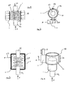
- a cylindrical spring element 1 is shown, which is made for example of a suitable elastomer.
- the spring element 1 is connected on the opposite sides with a connecting piece 10 or 12 (see FIGS. 1 to 3 ).
- the nozzle 10 is connected, for example, to the chassis of a chassis, for example an industrial truck, while the nozzle (12) is connected, for example, to a wheel, in particular a support wheel of the vehicle.
- the forces acting on the spring element 1 are designated by F.
- a radial extension of the spring element results, as indicated by dashed lines at 14 ( FIG. 1 ).
- surface elements 4 are arranged, which have a distance S1 to the spring element.
- the surface elements 16 can be adjusted radially to the spring element 1 to or from this fort to increase the gap width S1 or reduce. Accordingly, the surface elements 4 form a boundary for the radial extent of the spring element 1. Such a limitation leads to a Change in the spring characteristic of the spring element 1 regardless of a spring preload.
- An adjusting device with which the surface elements 4 can be adjusted, is not shown. This can be formed, for example, by an adjusting cylinder which is operated hydraulically, pneumatically or electromechanically. The adjusting device is controlled for example by the load, which is transported by the vehicle, for example industrial truck, or by other operating parameters such as steering angle, etc.
- FIG. 2 will be the spring element that is different than in FIG. 1 Is shown from above, surrounded by two half-shells 4a, which are articulated at one end at 18 to each other and at the other end with an adjusting cylinder 5 in connection. One end is connected to the cylinder of the adjusting cylinder 5 and the other end to the piston of the adjusting cylinder 5.
- the half shells 4a can be opened more or less correspondingly to the double arrows 20 in order to change the variable gap S1 to the spring element 1 in its size.
- FIG. 3 a completed housing 2 is shown, in which the spring element 1 is arranged.
- the nozzles 10, 12 are pistons which extend sealingly out of the housing 2.
- the arrangement of the spring member 1 is the same as that of the embodiments described above.
- Via a pressure connection 22, a liquid or gaseous fluid 24 in the housing 2 can be placed under a corresponding pressure.
- the spring constant of the spring element 1 changes, so that the spring characteristic of the spring element 1 can be adjusted as a function of pressure and thus in turn as a function of the load.
- FIG. 4 is around the upper portion of the spring element 1, an annular body 4b placed around (the upper nozzle 10 is not shown in this drawing).
- the annular body 4b is connected to a cylinder 5 or an electromechanical actuator whose piston rod 6 is supported on an abutment, not shown.
- the ring body 4b can therefore be provided axially displaced relative to the spring element 1, as indicated by double arrow 26.
- the actuation of the adjusting cylinder 5 again takes place, for example, as a function of an operating parameter of a vehicle, in particular, for example, of its load.
Landscapes
- Engineering & Computer Science (AREA)
- General Engineering & Computer Science (AREA)
- Mechanical Engineering (AREA)
- Springs (AREA)
- Vehicle Body Suspensions (AREA)
Abstract
Description
- Die Erfindung bezieht sich auf eine Federanordnung nach Patentanspruch 1.
- Federn zeichnen sich bekanntlich durch ihre Federkonstante bzw. ihre Kennlinie aus. Man unterscheidet zwischen Zug-, Druck- und Drehfedern mit linearer, progressiver und degressiver Federcharakteristik.
- Federanordnungen werden häufig bei Fahrwerken von Fahrzeugen eingesetzt, unter anderem auch bei Flurförderzeugen, um die Übertragung von Stößen an den Rädern auf das Chassis abzumildern und/oder bei Kurvenfahrt gute Seitenstabilität zu gewährleisten. Es ist bekannt, die Fahrwerksfedern abhängig von Betriebsparametern vorzuspannen. Wenn vor- und nachstehend von Betriebsparametern die Rede ist, sind neben der Last z.B. Lenkwinkel, Beschleunigung/Verzögerung, Neigungswinkel, Lasthöhe, Fahrzeugseitenneigung usw. gemeint. Der Arbeits-bereich verschiebt sich somit entlang der Federkennlinie. Bei linearen Federn bleibt die Federcharakteristik in jedem Arbeitsbereich konstant, bei progressiven und degressiven Federn ändert sich jedoch die Federcharakteristik je nach Lage des Arbeitsbereiches auf der Federkennlinie und somit die Abhängigkeit der eingeleiteten Federvorspannung. Bei einem Fahrwerk mit Stützrollen (Flurförderzeug) bedeutet einer Erhöhung der Stützrollenlast eine Verminderung der Antriebsradlast, was unerwünscht ist.
- Häufig besteht aber der Wunsch, die Federkennlinie von Betriebsparametern abhängig zu machen, beispielsweise von der Last auf einem Flurförderzeug.
- Daher liegt der Erfmdung die Aufgabe zu Grunde, eine Federanordnung zu schaffen, bei der abhängig von einem Betriebsparameter die Federcharakteristik geändert werden kann, insbesondere ohne dabei die Federvorspannkraft zu variieren.
- Diese Aufgabe wird durch die Merkmale des Patentanspruchs 1 gelöst.
- Bei der erfindungsgemäßen Federanordnung sind dem Federelement Mittel zugeordnet, die beim Aufbringen einer Axialkraft auf das Federelement zumindest über einen Teil der axialen Länge des Federelements seine radiale Ausdehnung begrenzen. Alternativ wird der radialen Ausdehnung ein Widerstand entgegengesetzt.
- Wird zum Beispiel ein Federelement aus einem elastomeren Material in seiner radialen Ausdehnung begrenzt, kann eine weitere Ausdehnung des Federelements nur noch in axiale Richtung stattfinden. Auf diese Weise wird die Federkennlinie des Elements geändert.
- Nach einer Ausgestaltung der Erfindung ist mit den Mitteln zur Erzeugung eines Widerstandes oder einer Begrenzung für das Federelement eine Verstelleinrichtung gekoppelt. Diese kann ihrerseits von einem Betriebsparameter gesteuert werden. Mit Hilfe der Steuereinrichtung und erfindungsgemäßen Federanordnung lässt sich daher das Federverhalten des Federelements in Grenzen variieren, beispielsweise an die Last eines Flurförderzeugs anzupassen.
- Es sind verschiedene konstruktive Möglichkeiten denkbar, das Federelement in seiner Federcharakteristik zu beeinflussen. Eine Ausgestaltung der Erfindung sieht hierzu vor, dass die Mittel mindestens zwei Flächenelemente aufweisen, die sich auf gegenüberliegenden Seiten des Federelements annähernd parallel zu diesem über mindestens einen Teil seiner axialen Länge erstrecken, wobei die Federelemente von der Verstelleinrichtung so betätigbar sind, dass ihr radialer Abstand zum Federelement verändert wird. Das Federelement ist dabei an einer Ausdehnung bei Belastung über ein bestimmtes Maß hinaus gehindert und kann sich zum Beispiel nur in axialer Richtung verformen.
- Nach einer weiteren Ausgestaltung hierzu ist erfindungsgemäß vorgesehen, dass die Flächenelemente zwei Halbschalen aufweisen, die an einem Ende aneinander angelenkt und mit den anderen Enden mit der Verstellvorrichtung verbunden sind, wodurch der Abstand der anderen Enden voneinander einstellbar ist. Auch hierdurch kann die Ausdehnung des Federelements in radialer Richtung variabel begrenzt werden.
- In einer anderen Ausgestaltung der Erfindung ist vorgesehen, dass die Mittel einen Mantel aufweisen, der das Federelement zumindest über einen Teil seiner axialen Länge umgibt und mit der Verstelleinrichtung die relative axiale Lage von Mantel und Federelement veränderbar ist. Mit Hilfe des Mantels lässt sich der Bereich, der bei einer Belastung des Federelements radial ausgedehnt werden kann, verändern.
- In einer dritten Ausgestaltung der Erfindung ist vorgesehen, dass die Mittel ein Gehäuse aufweisen, das das Federelement annähernd abgedichtet aufnimmt und dessen Inneres mit einer Fluidquelle unter Druck verbunden ist, wobei mit der Verstelleinrichtung der Druck im Gehäuse einstellbar ist. Das Fluid kann ein Gas oder eine Flüssigkeit sein. Bei dieser Ausgestaltung wird der Vorteil erhalten, dass ein reibungsloses Medium das Federelement umgibt, wodurch ein Abrieb des Federelements verhindert wird.
- Die erfindungsgemäße Federanordnung ist insbesondere für ein Rad eines Flurförderzeugs verwendbar, insbesondere für ein Stützrad, wobei mit Hilfe der Verstelleinrichtung das Federverhalten am Stützrad abhängig von einem oder mehreren Betriebsparametern beeinflussbar ist.
- Die Erfindung wird nachfolgend anhand von Zeichnungen näher erläutert.
- Figur 1
- zeigt eine erste Ausführungsform der erfindungsgemäßen Federanordnung.
- Figur 2
- zeigt eine zweite Ausführungsform einer erfmdungsgemäßen Federanordnung.
- Figur 3
- zeigt eine dritte Ausführungsgemäßen einer erfindungsgemäßen Federanordnung.
- Figur 4
- zeigt eine vierte Ausführungsform einer erfindungsgemäßen Federanordnung.
- In den
Figuren 1 bis 4 ist ein zylindrisches Federelement 1 dargestellt, das zum Beispiel aus einem geeigneten Elastomer gefertigt ist. Das Federelement 1 ist an den entgegengesetzten Seiten mit einem Stutzen 10 bzw. 12 verbunden (sieheFiguren 1 bis 3 ). Der Stutzen 10 ist zum Beispiel mit dem Chassis eines Fahrwerks, beispielsweise eines Flurförderzeugs verbunden, während der Stutzen (12) zum Beispiel mit einem Rad, insbesondere einem Stützrad des Fahrzeugs verbunden ist. Die auf das Federelement 1 einwirkenden Kräfte sind mit F bezeichnet. Bei einer axialen Beaufschlagung ergibt sich eine radiale Ausdehnung des Federelements, wie gestrichelt bei 14 gezeichnet (Figur 1 ). Auf gegenüberliegenden Seiten des Federelements 1 sind Flächenelemente 4 angeordnet, die einen Abstand S1 zum Federelement aufweisen. Sie erstrecken sich annähernd über die Höhe des Federelements 1. Wie durch die Pfeile 16 angedeutet, können die Flächenelemente 16 radial auf das Federelement 1 zu oder von diesem fort eingestellt werden, um die Spaltbreite S1 zu erhöhen oder zu verringern. Entsprechend bilden die Flächenelemente 4 eine Begrenzung für die radiale Ausdehnung des Federelements 1. Eine derartige Begrenzung führt zu einer Veränderung der Federcharakteristik des Federelements 1 unabhängig von einer Federvorspannung. - Eine Verstelleinrichtung, mit welcher die Flächenelemente 4 verstellt werden können, ist nicht dargestellt. Diese kann zum Beispiel von einem Verstellzylinder, der hydraulisch, pneumatisch oder elektromechanisch betrieben ist, gebildet sein. Die Verstelleinrichtung wird zum Beispiel durch die Last gesteuert, welche vom Fahrzeug, zum Beispiel Flurförderzeug, transportiert wird oder auch von anderen Betriebsparametern wie Lenkwinkel etc.
- In
Figur 2 wird das Federelement, das anders als inFigur 1 von oben gezeigt ist, von zwei Halbschalen 4a umgeben, die an einem Ende bei 18 aneinander angelenkt und am anderen Ende mit einem Verstellzylinder 5 in Verbindung sind. Das eine Ende ist mit dem Zylinder des Verstellzylinders 5 und das andere Ende mit dem Kolben des Verstellzylinders 5 verbunden. Dadurch können die Halbschalen 4a entsprechend den Doppelpfeilen 20 mehr oder weniger geöffnet werden, um den hier variablen Spalt S1 zum Federelement 1 in seiner Größe zu verändern. Die Betätigung des Verstellzylinders 5, der mit dem Druck P beaufschlagt wird, ist wiederum abhängig von einer Steuervorrichtung, die hier nicht gezeigt ist und die die Last am Fahrzeug in ein entsprechendes Drucksignal umwandelt, um eine lastabhängige Beeinflussung der Federcharakteristik des Federelements 1 zu erzielen. - In
Figur 3 ist ein abgeschlossenes Gehäuse 2 dargestellt, in welchem das Federelement 1 angeordnet ist. Die Stutzen 10, 12 sind Kolben, die sich dichtend aus dem Gehäuse 2 heraus erstrecken. Die Anordnung des Federelements 1 ist im Übrigen die gleiche wie zu den weiter oben beschriebenen Ausfiihrungsformen. Über einen Druckanschluss 22 kann ein flüssiges oder gasförmiges Fluid 24 im Gehäuse 2 unter einen entsprechenden Druck gesetzt werden. In Abhängigkeit von diesem Druck ändert sich die Federkonstante des Federelements 1, sodass druckabhängig und somit wiederum lastabhängig die Federcharakteristik des Federelements 1 eingestellt werden kann. - In
Figur 4 ist um den oberen Bereich des Federelements 1 ein Ringkörper 4b herum gelegt (der obere Stutzen 10 ist in dieser Zeichnung nicht dargestellt). Der Ringkörper 4b ist mit einem Zylinder 5 oder einem elektromechanischem Stellorgan verbunden, dessen Kolbenstange 6 an einem nicht gezeigten Widerlager abgestützt ist. Durch die Zuführung von Druckmitteln mit dem Druck P über den Anschluss 8 des Verstellzylinders 5 kann mithin der Ringkörper 4b axial relativ zum Federelement 1 vertellt werden, wie durch Doppelpfeil 26 angedeutet. Mit Hilfe dieser Vorkehrung lässt sich daher ebenfalls das Federverhalten des Federelements 1 abhängig von der axialen Position des Ringkörpers 4b einstellen. Die Betätigung des Verstellzylinders 5 erfolgt wiederum zum Beispiel in Abhängigkeit von einem Betriebsparameter eines Fahrzeugs, insbesondere zum Beispiel von seiner Last.
Claims (9)
- Federanordnung, bei der ein Federelement von einer variablen axialen Kraft beaufschlagt und sowohl in radialer als auch in axialer Richtung dehnbar ausgebildet ist, dadurch gekennzeichnet, dass dem Federelement (1) Mittel zugeordnet sind, die beim Aufbringen einer Axialkraft zumindest über einen Teil der axialen Länge dem Federelement (1) seiner radialen Ausdehnung einen Widerstand entgegensetzen oder das Federelement (1) in seiner radialen Ausdehnung begrenzen.
- Federanordnung nach Anspruch 1, dadurch gekennzeichnet, dass das Federelement (1) ein Körper aus elastomerem Material ist.
- Federanordnung nach Anspruch 1 oder 2, dadurch gekennzeichnet, dass die Mittel mindestens zwei Flächenelemente (4) aufweisen, die sich auf gegenüberliegenden Seiten des Federelements 1 annähernd parallel zu diesen über mindestens einen Teil seiner axialen Länge erstrecken und die Flächenelemente (4) von der Verstelleinrichtung so betätigbar sind, dass ihr radialer Abstand S1 zum Federelement (1) verändert wird.
- Federanordnung nach einem der Ansprüche 1 bis 3, dadurch gekennzeichnet, dass die den Widerstand oder die Begrenzung erzeugenden Mittel veränderbar und von einer Verstelleinrichtung einstellbar sind.
- Federanordnung nach Anspruch 3, dadurch gekennzeichnet, dass die Flächenelemente zwei Halbschalen (4a) aufweisen, die an einem Ende aneinander angelenkt sind und mit den anderen Enden mit der Verstelleinrichtung verbunden sind, wodurch der Abstand der anderen Enden voneinander einstellbar ist.
- Federanordnung nach einem der Ansprüche 1 bis 3, dadurch gekennzeichnet, dass die Mittel einen Mantel (4b) aufweisen, der das Federelement (1) zumindest über einen Teil seiner axialen Länge umgibt und mit der Verstelleinrichtung die relative axiale Lage von Mantel (4b) und Federelement (1) veränderbar ist.
- Federanordnung nach einem der Ansprüche 1 bis 3, dadurch gekennzeichnet, dass die Mittel ein Gehäuse (2) aufweisen, die das Federelement (1) annähernd abgedichtet aufnimmt, das Innere des Gehäuses (2) mit einer Fluidquelle unter Druck verbindbar ist und mit der Verstelleinrichtung der Druck im Gehäuse (2) einstellbar ist.
- Federanordnung nach Anspruch 7, dadurch gekennzeichnet, dass das Fluid ein Gas oder eine Flüssigkeit ist.
- Federanordnung nach einem der Ansprüche 1 bis 8, dadurch gekennzeichnet, dass sie ein Rad eines Flurförderzeugs, insbesondere ein Stützrad, gegenüber dem Chassis des Flurförderzeugs abstützt und die Verstelleinrichtung von der Last bzw. dem Gewicht des Flurförderzeugs oder einem anderen Betriebsparameter gesteuert ist.
Applications Claiming Priority (1)
| Application Number | Priority Date | Filing Date | Title |
|---|---|---|---|
| DE200810047023 DE102008047023A1 (de) | 2008-09-13 | 2008-09-13 | Federanordnung |
Publications (2)
| Publication Number | Publication Date |
|---|---|
| EP2163781A1 true EP2163781A1 (de) | 2010-03-17 |
| EP2163781B1 EP2163781B1 (de) | 2013-04-24 |
Family
ID=41346044
Family Applications (1)
| Application Number | Title | Priority Date | Filing Date |
|---|---|---|---|
| EP09009593.6A Not-in-force EP2163781B1 (de) | 2008-09-13 | 2009-07-24 | Federanordnung |
Country Status (2)
| Country | Link |
|---|---|
| EP (1) | EP2163781B1 (de) |
| DE (1) | DE102008047023A1 (de) |
Families Citing this family (3)
| Publication number | Priority date | Publication date | Assignee | Title |
|---|---|---|---|---|
| DE102008057577B4 (de) * | 2008-11-15 | 2017-01-05 | Bayerische Motoren Werke Aktiengesellschaft | Elastomer-Lager und Verfahren zur Variation seiner Federsteifigkeit |
| DE102014200118B4 (de) * | 2013-01-17 | 2017-11-09 | Ford Global Technologies, Llc | Feder- und Dämpfungsvorrichtung mit einem Schraubenfederelement und einem Gummifederelement |
| DE102024138846B3 (de) | 2024-12-19 | 2026-05-21 | Otto Bock Healthcare Products Gmbh | Orthopädietechnische Einrichtung |
Citations (5)
| Publication number | Priority date | Publication date | Assignee | Title |
|---|---|---|---|---|
| BE683075A (de) * | 1965-06-25 | 1966-12-01 | ||
| JPS5643029A (en) * | 1979-09-19 | 1981-04-21 | Nissan Motor Co Ltd | Engine supporting device |
| JPS59140935A (ja) * | 1983-01-31 | 1984-08-13 | Hino Motors Ltd | ラバ−マウンテイング |
| JPS60201132A (ja) * | 1984-03-26 | 1985-10-11 | Hino Motors Ltd | マウントラバ−の構造 |
| EP0919404A2 (de) | 1997-11-28 | 1999-06-02 | BT Industries Aktiebolag | Radaufhängungseinrichtung eines Hubwagens |
-
2008
- 2008-09-13 DE DE200810047023 patent/DE102008047023A1/de not_active Withdrawn
-
2009
- 2009-07-24 EP EP09009593.6A patent/EP2163781B1/de not_active Not-in-force
Patent Citations (5)
| Publication number | Priority date | Publication date | Assignee | Title |
|---|---|---|---|---|
| BE683075A (de) * | 1965-06-25 | 1966-12-01 | ||
| JPS5643029A (en) * | 1979-09-19 | 1981-04-21 | Nissan Motor Co Ltd | Engine supporting device |
| JPS59140935A (ja) * | 1983-01-31 | 1984-08-13 | Hino Motors Ltd | ラバ−マウンテイング |
| JPS60201132A (ja) * | 1984-03-26 | 1985-10-11 | Hino Motors Ltd | マウントラバ−の構造 |
| EP0919404A2 (de) | 1997-11-28 | 1999-06-02 | BT Industries Aktiebolag | Radaufhängungseinrichtung eines Hubwagens |
Also Published As
| Publication number | Publication date |
|---|---|
| DE102008047023A1 (de) | 2010-03-18 |
| EP2163781B1 (de) | 2013-04-24 |
Similar Documents
| Publication | Publication Date | Title |
|---|---|---|
| DE102018125965B4 (de) | Nichtlineares steifheits-stellglied für eine fahrzeugaufhängung | |
| DE102011107143B4 (de) | Steifigkeitssteuerung unter Verwendung von intelligenten Aktuatoren | |
| EP2550168B1 (de) | Luftfederanordnung mit integriertem steuerventil | |
| DE112013004595B4 (de) | Aufhängungsvorrichtung | |
| EP1862337B1 (de) | Verfahren zur Niveauregulierung bei einem Kraftfahrzeug | |
| WO2000071371A1 (de) | Stabilisator für ein kraftfahrzeug | |
| DE2239444A1 (de) | Radaufhaengung fuer zweiradfahrzeuge | |
| DE3512047A1 (de) | Radaufhaengungs-system fuer fahrzeuge | |
| DE1505522B1 (de) | Hydropneumatischer Einrohr-Teleskopstossdaempfer mit davon unabhaengiger,parallel geschalteter Gasfeder und selbsttaetig steuerbarem Daempfungsgrad,insbesondere fuer Kraftfahrzeuge | |
| EP1935680A1 (de) | Radaufhängung für ein Kraftfahrzeug | |
| DE4135900A1 (de) | Luftfeder, insbesondere fuer kraftfahrzeuge | |
| DE19753412C2 (de) | Gabelhubwagen mit verstellbarer Stützrolle | |
| DE2811034A1 (de) | Befestigungsauge, insbesondere fuer stossdaempfer | |
| EP4185760B1 (de) | Antriebsanordnung für eine klappe eines kraftfahrzeugs | |
| DE10301546B3 (de) | Federbein mit höhenverstellbarem Federteller | |
| EP2163781B1 (de) | Federanordnung | |
| DE3809995A1 (de) | Hintere aufhaengungseinrichtung fuer motorfahrzeuge | |
| DE3942654C2 (de) | Einrichtung zur Wankstabilisierung eines Fahrzeugs | |
| DE69225225T2 (de) | Fahrzeugaufhängung | |
| DE102014114861A1 (de) | Fahrzeug-Aufhängungsvorrichtung mit einer Stange und einer Karosserie-Lastreaktionskomponente zum Regeln der Bodenfreiheit | |
| DE102008007566B4 (de) | Schwingungsfluiddämpfung- und/oder -federung | |
| DE69404276T2 (de) | Servolenkungssystem | |
| DE2322997C2 (de) | Dämpfungsvorrichtung für hydropneumatische Fahrzeugfedern | |
| DE602005005009T2 (de) | Stoßdämpfer | |
| DE10336155B3 (de) | Federbein |
Legal Events
| Date | Code | Title | Description |
|---|---|---|---|
| PUAI | Public reference made under article 153(3) epc to a published international application that has entered the european phase |
Free format text: ORIGINAL CODE: 0009012 |
|
| AK | Designated contracting states |
Kind code of ref document: A1 Designated state(s): AT BE BG CH CY CZ DE DK EE ES FI FR GB GR HR HU IE IS IT LI LT LU LV MC MK MT NL NO PL PT RO SE SI SK SM TR |
|
| AX | Request for extension of the european patent |
Extension state: AL BA RS |
|
| 17P | Request for examination filed |
Effective date: 20100909 |
|
| 17Q | First examination report despatched |
Effective date: 20120906 |
|
| GRAP | Despatch of communication of intention to grant a patent |
Free format text: ORIGINAL CODE: EPIDOSNIGR1 |
|
| GRAS | Grant fee paid |
Free format text: ORIGINAL CODE: EPIDOSNIGR3 |
|
| GRAA | (expected) grant |
Free format text: ORIGINAL CODE: 0009210 |
|
| AK | Designated contracting states |
Kind code of ref document: B1 Designated state(s): AT BE BG CH CY CZ DE DK EE ES FI FR GB GR HR HU IE IS IT LI LT LU LV MC MK MT NL NO PL PT RO SE SI SK SM TR |
|
| REG | Reference to a national code |
Ref country code: GB Ref legal event code: FG4D Free format text: NOT ENGLISH |
|
| REG | Reference to a national code |
Ref country code: CH Ref legal event code: EP |
|
| REG | Reference to a national code |
Ref country code: AT Ref legal event code: REF Ref document number: 608802 Country of ref document: AT Kind code of ref document: T Effective date: 20130515 |
|
| REG | Reference to a national code |
Ref country code: IE Ref legal event code: FG4D Free format text: LANGUAGE OF EP DOCUMENT: GERMAN |
|
| REG | Reference to a national code |
Ref country code: DE Ref legal event code: R096 Ref document number: 502009006914 Country of ref document: DE Effective date: 20130620 |
|
| REG | Reference to a national code |
Ref country code: LT Ref legal event code: MG4D |
|
| REG | Reference to a national code |
Ref country code: NL Ref legal event code: VDEP Effective date: 20130424 |
|
| PG25 | Lapsed in a contracting state [announced via postgrant information from national office to epo] |
Ref country code: SE Free format text: LAPSE BECAUSE OF FAILURE TO SUBMIT A TRANSLATION OF THE DESCRIPTION OR TO PAY THE FEE WITHIN THE PRESCRIBED TIME-LIMIT Effective date: 20130424 Ref country code: ES Free format text: LAPSE BECAUSE OF FAILURE TO SUBMIT A TRANSLATION OF THE DESCRIPTION OR TO PAY THE FEE WITHIN THE PRESCRIBED TIME-LIMIT Effective date: 20130804 Ref country code: NO Free format text: LAPSE BECAUSE OF FAILURE TO SUBMIT A TRANSLATION OF THE DESCRIPTION OR TO PAY THE FEE WITHIN THE PRESCRIBED TIME-LIMIT Effective date: 20130724 Ref country code: GR Free format text: LAPSE BECAUSE OF FAILURE TO SUBMIT A TRANSLATION OF THE DESCRIPTION OR TO PAY THE FEE WITHIN THE PRESCRIBED TIME-LIMIT Effective date: 20130725 Ref country code: FI Free format text: LAPSE BECAUSE OF FAILURE TO SUBMIT A TRANSLATION OF THE DESCRIPTION OR TO PAY THE FEE WITHIN THE PRESCRIBED TIME-LIMIT Effective date: 20130424 Ref country code: PT Free format text: LAPSE BECAUSE OF FAILURE TO SUBMIT A TRANSLATION OF THE DESCRIPTION OR TO PAY THE FEE WITHIN THE PRESCRIBED TIME-LIMIT Effective date: 20130826 Ref country code: SI Free format text: LAPSE BECAUSE OF FAILURE TO SUBMIT A TRANSLATION OF THE DESCRIPTION OR TO PAY THE FEE WITHIN THE PRESCRIBED TIME-LIMIT Effective date: 20130424 Ref country code: LT Free format text: LAPSE BECAUSE OF FAILURE TO SUBMIT A TRANSLATION OF THE DESCRIPTION OR TO PAY THE FEE WITHIN THE PRESCRIBED TIME-LIMIT Effective date: 20130424 Ref country code: IS Free format text: LAPSE BECAUSE OF FAILURE TO SUBMIT A TRANSLATION OF THE DESCRIPTION OR TO PAY THE FEE WITHIN THE PRESCRIBED TIME-LIMIT Effective date: 20130824 |
|
| PG25 | Lapsed in a contracting state [announced via postgrant information from national office to epo] |
Ref country code: BG Free format text: LAPSE BECAUSE OF FAILURE TO SUBMIT A TRANSLATION OF THE DESCRIPTION OR TO PAY THE FEE WITHIN THE PRESCRIBED TIME-LIMIT Effective date: 20130724 Ref country code: PL Free format text: LAPSE BECAUSE OF FAILURE TO SUBMIT A TRANSLATION OF THE DESCRIPTION OR TO PAY THE FEE WITHIN THE PRESCRIBED TIME-LIMIT Effective date: 20130424 Ref country code: CY Free format text: LAPSE BECAUSE OF FAILURE TO SUBMIT A TRANSLATION OF THE DESCRIPTION OR TO PAY THE FEE WITHIN THE PRESCRIBED TIME-LIMIT Effective date: 20130424 Ref country code: HR Free format text: LAPSE BECAUSE OF FAILURE TO SUBMIT A TRANSLATION OF THE DESCRIPTION OR TO PAY THE FEE WITHIN THE PRESCRIBED TIME-LIMIT Effective date: 20130424 Ref country code: LV Free format text: LAPSE BECAUSE OF FAILURE TO SUBMIT A TRANSLATION OF THE DESCRIPTION OR TO PAY THE FEE WITHIN THE PRESCRIBED TIME-LIMIT Effective date: 20130424 |
|
| BERE | Be: lapsed |
Owner name: JUNGHEINRICH A.G. Effective date: 20130731 |
|
| PG25 | Lapsed in a contracting state [announced via postgrant information from national office to epo] |
Ref country code: EE Free format text: LAPSE BECAUSE OF FAILURE TO SUBMIT A TRANSLATION OF THE DESCRIPTION OR TO PAY THE FEE WITHIN THE PRESCRIBED TIME-LIMIT Effective date: 20130424 Ref country code: DK Free format text: LAPSE BECAUSE OF FAILURE TO SUBMIT A TRANSLATION OF THE DESCRIPTION OR TO PAY THE FEE WITHIN THE PRESCRIBED TIME-LIMIT Effective date: 20130424 Ref country code: SK Free format text: LAPSE BECAUSE OF FAILURE TO SUBMIT A TRANSLATION OF THE DESCRIPTION OR TO PAY THE FEE WITHIN THE PRESCRIBED TIME-LIMIT Effective date: 20130424 Ref country code: CZ Free format text: LAPSE BECAUSE OF FAILURE TO SUBMIT A TRANSLATION OF THE DESCRIPTION OR TO PAY THE FEE WITHIN THE PRESCRIBED TIME-LIMIT Effective date: 20130424 |
|
| PG25 | Lapsed in a contracting state [announced via postgrant information from national office to epo] |
Ref country code: IT Free format text: LAPSE BECAUSE OF FAILURE TO SUBMIT A TRANSLATION OF THE DESCRIPTION OR TO PAY THE FEE WITHIN THE PRESCRIBED TIME-LIMIT Effective date: 20130424 Ref country code: RO Free format text: LAPSE BECAUSE OF FAILURE TO SUBMIT A TRANSLATION OF THE DESCRIPTION OR TO PAY THE FEE WITHIN THE PRESCRIBED TIME-LIMIT Effective date: 20130424 Ref country code: MC Free format text: LAPSE BECAUSE OF FAILURE TO SUBMIT A TRANSLATION OF THE DESCRIPTION OR TO PAY THE FEE WITHIN THE PRESCRIBED TIME-LIMIT Effective date: 20130424 Ref country code: NL Free format text: LAPSE BECAUSE OF FAILURE TO SUBMIT A TRANSLATION OF THE DESCRIPTION OR TO PAY THE FEE WITHIN THE PRESCRIBED TIME-LIMIT Effective date: 20130424 |
|
| PLBE | No opposition filed within time limit |
Free format text: ORIGINAL CODE: 0009261 |
|
| REG | Reference to a national code |
Ref country code: CH Ref legal event code: PL |
|
| STAA | Information on the status of an ep patent application or granted ep patent |
Free format text: STATUS: NO OPPOSITION FILED WITHIN TIME LIMIT |
|
| 26N | No opposition filed |
Effective date: 20140127 |
|
| REG | Reference to a national code |
Ref country code: IE Ref legal event code: MM4A |
|
| PG25 | Lapsed in a contracting state [announced via postgrant information from national office to epo] |
Ref country code: BE Free format text: LAPSE BECAUSE OF NON-PAYMENT OF DUE FEES Effective date: 20130731 Ref country code: LI Free format text: LAPSE BECAUSE OF NON-PAYMENT OF DUE FEES Effective date: 20130731 Ref country code: CH Free format text: LAPSE BECAUSE OF NON-PAYMENT OF DUE FEES Effective date: 20130731 |
|
| REG | Reference to a national code |
Ref country code: DE Ref legal event code: R097 Ref document number: 502009006914 Country of ref document: DE Effective date: 20140127 |
|
| PG25 | Lapsed in a contracting state [announced via postgrant information from national office to epo] |
Ref country code: IE Free format text: LAPSE BECAUSE OF NON-PAYMENT OF DUE FEES Effective date: 20130724 |
|
| PG25 | Lapsed in a contracting state [announced via postgrant information from national office to epo] |
Ref country code: SM Free format text: LAPSE BECAUSE OF FAILURE TO SUBMIT A TRANSLATION OF THE DESCRIPTION OR TO PAY THE FEE WITHIN THE PRESCRIBED TIME-LIMIT Effective date: 20130424 |
|
| PG25 | Lapsed in a contracting state [announced via postgrant information from national office to epo] |
Ref country code: MT Free format text: LAPSE BECAUSE OF FAILURE TO SUBMIT A TRANSLATION OF THE DESCRIPTION OR TO PAY THE FEE WITHIN THE PRESCRIBED TIME-LIMIT Effective date: 20130424 Ref country code: TR Free format text: LAPSE BECAUSE OF FAILURE TO SUBMIT A TRANSLATION OF THE DESCRIPTION OR TO PAY THE FEE WITHIN THE PRESCRIBED TIME-LIMIT Effective date: 20130424 |
|
| PG25 | Lapsed in a contracting state [announced via postgrant information from national office to epo] |
Ref country code: LU Free format text: LAPSE BECAUSE OF NON-PAYMENT OF DUE FEES Effective date: 20130724 Ref country code: HU Free format text: LAPSE BECAUSE OF FAILURE TO SUBMIT A TRANSLATION OF THE DESCRIPTION OR TO PAY THE FEE WITHIN THE PRESCRIBED TIME-LIMIT; INVALID AB INITIO Effective date: 20090724 Ref country code: MK Free format text: LAPSE BECAUSE OF FAILURE TO SUBMIT A TRANSLATION OF THE DESCRIPTION OR TO PAY THE FEE WITHIN THE PRESCRIBED TIME-LIMIT Effective date: 20130424 |
|
| REG | Reference to a national code |
Ref country code: AT Ref legal event code: MM01 Ref document number: 608802 Country of ref document: AT Kind code of ref document: T Effective date: 20140724 |
|
| PG25 | Lapsed in a contracting state [announced via postgrant information from national office to epo] |
Ref country code: AT Free format text: LAPSE BECAUSE OF NON-PAYMENT OF DUE FEES Effective date: 20140724 |
|
| REG | Reference to a national code |
Ref country code: FR Ref legal event code: PLFP Year of fee payment: 8 |
|
| REG | Reference to a national code |
Ref country code: FR Ref legal event code: PLFP Year of fee payment: 9 |
|
| REG | Reference to a national code |
Ref country code: FR Ref legal event code: PLFP Year of fee payment: 10 |
|
| PGFP | Annual fee paid to national office [announced via postgrant information from national office to epo] |
Ref country code: GB Payment date: 20200724 Year of fee payment: 12 |
|
| GBPC | Gb: european patent ceased through non-payment of renewal fee |
Effective date: 20210724 |
|
| PG25 | Lapsed in a contracting state [announced via postgrant information from national office to epo] |
Ref country code: GB Free format text: LAPSE BECAUSE OF NON-PAYMENT OF DUE FEES Effective date: 20210724 |
|
| PGFP | Annual fee paid to national office [announced via postgrant information from national office to epo] |
Ref country code: DE Payment date: 20220628 Year of fee payment: 14 |
|
| PGFP | Annual fee paid to national office [announced via postgrant information from national office to epo] |
Ref country code: FR Payment date: 20220725 Year of fee payment: 14 |
|
| REG | Reference to a national code |
Ref country code: DE Ref legal event code: R119 Ref document number: 502009006914 Country of ref document: DE |
|
| PG25 | Lapsed in a contracting state [announced via postgrant information from national office to epo] |
Ref country code: DE Free format text: LAPSE BECAUSE OF NON-PAYMENT OF DUE FEES Effective date: 20240201 |
|
| PG25 | Lapsed in a contracting state [announced via postgrant information from national office to epo] |
Ref country code: FR Free format text: LAPSE BECAUSE OF NON-PAYMENT OF DUE FEES Effective date: 20230731 |