EP2163697A2 - Nivellierungs- und Stützsystem - Google Patents
Nivellierungs- und Stützsystem Download PDFInfo
- Publication number
- EP2163697A2 EP2163697A2 EP09252180A EP09252180A EP2163697A2 EP 2163697 A2 EP2163697 A2 EP 2163697A2 EP 09252180 A EP09252180 A EP 09252180A EP 09252180 A EP09252180 A EP 09252180A EP 2163697 A2 EP2163697 A2 EP 2163697A2
- Authority
- EP
- European Patent Office
- Prior art keywords
- base plate
- levelling
- packer element
- panel
- wall
- Prior art date
- Legal status (The legal status is an assumption and is not a legal conclusion. Google has not performed a legal analysis and makes no representation as to the accuracy of the status listed.)
- Withdrawn
Links
Images


Classifications
-
- E—FIXED CONSTRUCTIONS
- E04—BUILDING
- E04B—GENERAL BUILDING CONSTRUCTIONS; WALLS, e.g. PARTITIONS; ROOFS; FLOORS; CEILINGS; INSULATION OR OTHER PROTECTION OF BUILDINGS
- E04B2/00—Walls, e.g. partitions, for buildings; Wall construction with regard to insulation; Connections specially adapted to walls
- E04B2/72—Non-load-bearing walls of elements of relatively thin form with respect to the thickness of the wall
-
- E—FIXED CONSTRUCTIONS
- E04—BUILDING
- E04B—GENERAL BUILDING CONSTRUCTIONS; WALLS, e.g. PARTITIONS; ROOFS; FLOORS; CEILINGS; INSULATION OR OTHER PROTECTION OF BUILDINGS
- E04B1/00—Constructions in general; Structures which are not restricted either to walls, e.g. partitions, or floors or ceilings or roofs
- E04B1/18—Structures comprising elongated load-supporting parts, e.g. columns, girders, skeletons
- E04B1/26—Structures comprising elongated load-supporting parts, e.g. columns, girders, skeletons the supporting parts consisting of wood
- E04B1/2604—Connections specially adapted therefor
- E04B1/2608—Connectors made from folded sheet metal
-
- E—FIXED CONSTRUCTIONS
- E04—BUILDING
- E04B—GENERAL BUILDING CONSTRUCTIONS; WALLS, e.g. PARTITIONS; ROOFS; FLOORS; CEILINGS; INSULATION OR OTHER PROTECTION OF BUILDINGS
- E04B2/00—Walls, e.g. partitions, for buildings; Wall construction with regard to insulation; Connections specially adapted to walls
- E04B2/72—Non-load-bearing walls of elements of relatively thin form with respect to the thickness of the wall
- E04B2/721—Non-load-bearing walls of elements of relatively thin form with respect to the thickness of the wall connections specially adapted therefor
-
- E—FIXED CONSTRUCTIONS
- E04—BUILDING
- E04B—GENERAL BUILDING CONSTRUCTIONS; WALLS, e.g. PARTITIONS; ROOFS; FLOORS; CEILINGS; INSULATION OR OTHER PROTECTION OF BUILDINGS
- E04B2/00—Walls, e.g. partitions, for buildings; Wall construction with regard to insulation; Connections specially adapted to walls
- E04B2/74—Removable non-load-bearing partitions; Partitions with a free upper edge
- E04B2/82—Removable non-load-bearing partitions; Partitions with a free upper edge characterised by the manner in which edges are connected to the building; Means therefor; Special details of easily-removable partitions as far as related to the connection with other parts of the building
- E04B2/825—Removable non-load-bearing partitions; Partitions with a free upper edge characterised by the manner in which edges are connected to the building; Means therefor; Special details of easily-removable partitions as far as related to the connection with other parts of the building the connection between the floor and the ceiling being achieved without any restraining forces acting in the plane of the partition
-
- E—FIXED CONSTRUCTIONS
- E04—BUILDING
- E04B—GENERAL BUILDING CONSTRUCTIONS; WALLS, e.g. PARTITIONS; ROOFS; FLOORS; CEILINGS; INSULATION OR OTHER PROTECTION OF BUILDINGS
- E04B1/00—Constructions in general; Structures which are not restricted either to walls, e.g. partitions, or floors or ceilings or roofs
- E04B1/18—Structures comprising elongated load-supporting parts, e.g. columns, girders, skeletons
- E04B1/26—Structures comprising elongated load-supporting parts, e.g. columns, girders, skeletons the supporting parts consisting of wood
- E04B1/2604—Connections specially adapted therefor
- E04B2001/268—Connection to foundations
-
- E—FIXED CONSTRUCTIONS
- E04—BUILDING
- E04B—GENERAL BUILDING CONSTRUCTIONS; WALLS, e.g. PARTITIONS; ROOFS; FLOORS; CEILINGS; INSULATION OR OTHER PROTECTION OF BUILDINGS
- E04B1/00—Constructions in general; Structures which are not restricted either to walls, e.g. partitions, or floors or ceilings or roofs
- E04B1/38—Connections for building structures in general
- E04B1/388—Separate connecting elements
- E04B2001/389—Brackets
Definitions
- the present invention relates to a levelling and support system and, in particular, to a levelling and support system for use in the construction/installation of walls and/or panels in buildings and other structures.
- the present invention has particular utility in the construction/installation of timber framed walls, or of other modular walls or panels used in the construction of a building or other structure.
- the walls and/or panels are typically built or installed on a foundation, substructure or other supporting surface/member.
- An example of the latter scenario is in multiple storey construction, and storey to storey connection in particular. It is important that loads from such walls and/or panels (comprising both horizontal and vertical loads) are properly transferred to the foundation, substructure or other supporting surface/member on which they are mounted or supported. It is also preferable that the walls and/or panels are mounted or supported in a substantially level orientation.
- any foundation, substructure or other supporting surface/member is provided in a reasonably level form to support the wall or panel.
- required tolerances are not always met and that gaps exist between the foundation, substructure or other supporting surface/member and a required level, requiring structural packing of up to 20mm or more thickness in certain circumstances.
- the lower sole plate is fixed to follow the contours of the supporting structure.
- the upper sole plate is fixed on top and levelled with temporary packers inserted between the sole plates. Permanent packers are to be inserted under each load point once the first lift construction has been erected.
- the present invention addresses this issue. Furthermore, the present invention addresses the problem of enabling a sole plate to be installed economically onto an uneven substructure, and of enabling an open panel timber frame wall section or other wall, panel or constructional element to be installed economically onto an uneven substructure.
- the present invention also addresses the problem of providing a system for quick and easy levelling of a timber or other sole plate (or other constructional element), and of providing a means of transferring vertical and horizontal loads from the sole plate or other constructional element to the substructure.
- the present invention also provides a means of aiding the accurate setting out of sole plates or other constructional elements.
- the present invention provides for levelling, support and anchoring of constructional elements against lateral and uplift forces.
- the present invention provides, in a first aspect, a levelling and support system comprising:
- the present invention provides a method of levelling and supporting a wall or panel or other structure comprising the steps of:
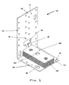
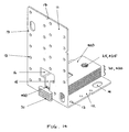
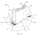
- a foundation, substructure or other supporting surface/member 101 provides support for a timber sole plate 40 of a wall or panel structure which further comprises a vertical timber stud member 42, a timber bottom rail 44 and a sheathing 46, typically plasterboard.
- the vertical timber stud 42 rests on or is connected to the timber sole plate 40 via a timber bottom rail 44, and the sheathing 46 provides a surface to the wall or panel, supported by the vertical stud member 42 and the sole plate 40.
- the sheathing 46 may extend to the foundation, substructure or other supporting surface/member 101, as shown, or may stop short.
- a skirting board (not shown) may be provided.
- gaps 50 may exist between the foundation, substructure or other supporting surface/member 101 and a required level (indicated by the level of the sole plate 40), resulting in the need for structural packing to fill the gaps 50.
- the levelling and support system bridges gaps 50 and comprises at least a base plate 10 and as many packer elements 20 as are required to fill the gap 50.
- the base plate 10 is first located in position and may be mechanically fixed to the foundation, substructure or other supporting surface/member 101 using one or more fasteners or anchors 30.
- Each packer element 20 is connected to the base plate 10 by means of a locking interaction of a T-shaped protrusion provided on the packer element 20 which can be inserted through a slot provided in the base plate 10 when the packer element 20 is in a first "insertion" position or configuration and which is restrained by the slot in the base plate 10 when the packer element 20 is in a second "in-use" position or configuration.
- the base plate 10 and packer element(s) 20 provide firstly the levelling means and secondly the vertical load transfer.
- the sole plate 40 may then be mechanically fixed to the base plate 10 of the levelling and support system using fasteners (not shown) to provide horizontal (lateral) load transfer and to prevent uplift in the vertical direction.
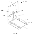
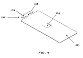
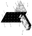
- the base plate 10 can be seen (see Figure 5 in particular) to comprise a vertical leg 11 and a horizontal leg 12 arranged substantially perpendicular to one another.
- Each leg 11, 12 is provided with a plurality of fixing holes 13 for flexibility and ease of installation, some of which may be elongate 14 to allow for extra flexibility of installation (i.e. to provide for installation tolerances).
- a slot 15 is provided in the base plate which extends at least partially along the centre of each leg 11, 12. At each end of the slot 15 is provided an aperture 16 for receiving a protrusion of a packer element 20.
- the provision of a slot 15 and aperture 16 in each leg 11, 12 provides for flexibility of installation as the base plate 10 may be used in more than one orientation.
- Each leg 11, 12 is also provided with a plurality of notches 17 to allow for the attachment of a string line(s) for flexibility and ease of installation.
- Each packer element 20 is substantially planar, of a prescribed thickness and comprises a T-shaped protrusion 21 (see Figure 6 in particular).
- the T-shaped protrusion comprising a head portion 22 and a leg portion 23, is provided for insertion through the aperture 16 of the base plate 10 when in a first "insertion" position or configuration.
- the leg portion 23 of the T-shape is then received in the slot 15 as the packer element 20 is slid down into the slot 15 provided in the base plate 10 until it rests on the leg 11, 12 of the base plate 10 (in the case that no other packer elements 20 have been employed) or on another packer element 20 (in the case that one or more other packer elements 20 have been employed).
- the head portion 22 of the T-shape is retained behind the leg 11, 12 by the slot 15 in the base plate 10 when the packer element 20 is in this second "in-use" position or configuration.
- the packer element 20 may avoid having to use the aperture 16 in the base plate 10 by being first orientated such that the planar body is vertical or almost vertical (i.e. rotated by up to 90 degrees along its longitudinal axis). This enables the head portion 22 of the T-shaped protrusion 21 to be inserted direct into the slot 15 of the base plate 10 when in a first "insertion” position or configuration.
- the packer element can then be orientated such that the planar body is horizontal or almost horizontal (i.e. rotated back by up to 90 degrees along its longitudinal axis).
- Each packer element 20 is also provided with a locking tab 24 integrally formed in the centre of the planar body. At least a portion of the locking tab 24 extends out of the plane of the packer element 20 and, in use, interacts with the aperture 16 of the leg 11, 12 of the base plate to aid in positioning and/or locking the packer element 20 in place. In the case that a packer element 20 is already in place, the locking tab 24 of the further packer element 20 interacts with the corresponding aperture formed by the locking tab 24 of the in-situ packer element 20 to aid in positioning and/or locking the packer element 20 in place. The locking tab 24 thus assists the T-shaped protrusion 21 in resisting lateral (horizontal) forces and movement.
- Each packer element 20 is also provided with fastener holes 25. These fastener holes 25 allow a mechanical fastener to pass through the packer element 20 and although not generally used, they may be used in certain installations where extreme lateral (horizontal) forces and movement could be encountered or where the packer element 20 is used independently of the base plate.
- FIG. 7 and 8 there are shown schematic front perspective views of alternative embodiments of base plate 110, 210 according to the present invention.
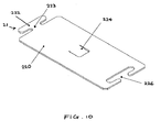
- FIG 7 there is shown a base plate 110 of more basic form than the base plate 10 of Figure 5 .
- the base plate 110 is suitable for use in only one orientation as the horizontal leg 112 does not comprise a slot 115 or aperture 116 for receiving the T-shaped protrusion 21 of a packer element 20.
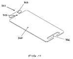
- a base plate 210 also of more basic form than the base plate 10 of Figure 5 .
- the base plate 210 is likewise suitable for use in only one orientation as the horizontal leg 212 does not comprise a slot 215 or aperture 16.
- the vertical leg 211 of base plate 210 does not comprise an aperture 16. Accordingly, when using a packer element 20, the head portion 22 of the T-shaped protrusion 21 must be inserted direct into the slot 215 of the vertical leg 211 of the base plate 210 in a first "insertion" position or configuration. This is achieved by first orientating the packer element 20 such that the planar body is vertical or almost vertical (i.e. rotated by up to 90 degrees along its longitudinal axis).
- the head portion 22 of the T-shaped protrusion 21 to be inserted direct into the slot 215 of the vertical leg 211 of the base plate 210 when in a first "insertion" position or configuration.
- the packer element 20 must then be orientated such that the planar body is horizontal or almost horizontal (i.e. rotated back by up to 90 degrees along its longitudinal axis).
- the horizontal leg 212 of base plate 210 comprises a raised guide potion 218 to aid screed levelling in an installation.
- one or more elongate slots 219 are provided in vertical leg 211 to allow the vertical leg to be easily bent over the top of the supported timber.
- base plate and respective slot and/or aperture configurations are possible, and that these may take any suitable form, e.g. no aperture 16, as illustrated in Figure 8 , or alternative shapes and configurations of slot and aperture, as illustrated in Figures 17 amd 18.
- the shape and form of the base plate can be varied as appropriate.
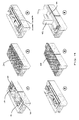
- FIG. 9 to 12 and Figure 14 there are shown schematic perspective illustrations of alternative embodiments of packer element 120, 220, 320, 420, 520 according to the present invention.
- the packer element 120 is identical to the packer element 20 described above in all respects apart from not being provided with the optional fastener holes 25.
- the packer element 220 is similar to the packer element 120, but is additionally provided with a female aperture 226 shaped so as to receive a T-shaped protrusion 21, 121, 221 of another packer element 20, 120, 220.
- This provides extra functionality (a modular system) as it permits respective packer elements to be connected together along their longitudinal axes, extending the length over which the support span can be provided (for use in the present system or where the packer elements are used independently of the base plate, or for use with an alternative form of base plate, e.g. one having one or more elongate legs upon which the extra length of packer element can rest).
- the packer element 320 is identical to the packer element 220 described above in all respects apart from not being provided with the optional locking tab 224.
- the packer element 420 is identical to the packer element 20 described above in all respects apart from not being provided with the T-shaped protrusion 21, 121, 221, 321. Instead, the packer element 420 is used in conjunction with other packer elements 20, 120, 220 provided with a T-shaped protrusion 21, 121, 221, 321, locking tab 24, 124, 224 and/or fastener holes 25, 225.
- packer element 20, 120, 220 In the case that a packer element 20, 120, 220 is already in place, or will be used in addition, the locking tab 24, 124, 224 or fastener holes 25, 225 of the or these other packer elements 20, 120, 220 interact(s) with the corresponding locking tab 424 and/or fastener holes 425 of packer element 420 to aid in positioning and/or locking the packer element 420 in place, thus assisting in resisting lateral (horizontal) forces and movement.
- packer elements 20, 120, 220 provided with the T-shaped protrusion 21, 121, 221, 321 are used alternately with packer elements 420 without a T-shaped protrusion 21, 121, 221, 321.
- these different packer elements 20, 120, 220, 420 need not be simply alternated; any suitable configuration may be adopted.
- the packer element 620 is identical to the packer element 20 described above in all respects apart from being provided with an additional locking tab 624. This aids in positioning and/or locking the packer element 620 in place.
- the locking tabs 624 may be provided in any suitable position or orientation. Indeed, more than two locking tabs 624 may be provided.
- FIG 15 there is schematically illustrated in perspective view a series of packer elements 520 of different thickness according to the present invention. Whilst the packer elements 520 can be seen to comprise only T-shaped protrusions 521, any feature or features of the alternative embodiments of packer elements 20, 120, 220, 320, 420 described above may be added, deleted or implemented in any configuration.
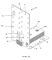
- a foundation, substructure or other supporting surface/member 201 provides support for a bottom plate 240 of a wall or panel structure which wall or panel structure further comprises a vertical stud member 242, insulation 244 and sheathing 246.
- Fasteners 248 connect together the bottom plate 240, vertical stud member 242 and sheathing 246.
- the sheathing 246 may extend to the foundation, substructure or other supporting surface/member 201, or stop short (as shown).
- a skirting board (not shown) may be provided.
- gaps 50 may exist between the foundation, substructure or other supporting surface/member 201 and a required level (indicated by the level of the bottom plate 240), resulting in the need for structural packing to fill the gaps 50.
- the levelling and support system bridges gaps 50 and comprises at least a base plate 10, 110, 210 and as many packer elements 20, 120, 220, 320, 420, 520, 620 as are required to fill the gap 50.
- the base plate 10, 110, 210 is first located in position and may be mechanically fixed to the foundation, substructure or other supporting surface/member 201 using one or more fasteners or anchors 30.
- Each packer element 20, 120, 220, 320, 420, 520, 620 is connected to the base plate 10, 110, 210 by means of its locking interaction (a T-shaped protrusion 21, 121, 221, 321, 521, 621 and/or locking tab 24, 124, 224 as described above).
- the base plate 10 and packer element(s) 20 provide firstly the levelling means and secondly the vertical load transfer.
- the bottom plate 240 and/or other one or more of any of the vertical stud member 242 and sheathing 246 may then be mechanically fixed to the base plate 10 of the levelling and support system using fasteners (not shown) to provide horizontal load transfer.
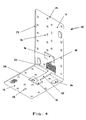
- the base plate 10 can be seen (see Figure 17 in particular) to comprise a vertical leg 11 and a horizontal leg 12 arranged substantially perpendicular to one another.
- Each leg 11, 12 is provided with a plurality of fixing holes 13 for flexibility and ease of installation.
- a slot 15 is provided in the base plate which extends at least partially along the centre of each leg 11, 12.
- At each end of the slot 15 is provided an off-set aperture 16 for receiving a protrusion of a packer element 20.
- the provision of a slot 15 and aperture 16 in each leg 11, 12 provides for flexibility of installation as the base plate 10 may be used in more than one orientation.
- Each packer element 20 is substantially planar, of a prescribed thickness and comprises a T-shaped protrusion 21 (see Figure 17 in particular).
- the T-shaped protrusion comprising a head portion 22 and a leg portion 23, is provided for insertion through the aperture 16 of the base plate 10 when in a first "insertion" position or configuration.
- the difference in this embodiment is that the packer element(s) 20 is/are inserted from, and in use positioned on, the other side of the "upstanding" leg 11, 12 of the base plate 10.
- the leg portion 23 of the T-shape of each packer element 20 is then received in the slot 15 as it is slid down into the slot 15 provided in the base plate 10 until it rests on the foundation, substructure or other supporting surface/member rather than the leg 11, 12 of the base plate 10 (in the case that no other packer elements 20 have been employed) or on another packer element 20 (in the case that one or more other packer elements 20 have been employed).
- the head portion 22 of the T-shape is retained behind the leg 11, 12 by the slot 15 in the base plate 10 when the packer element 20 is in this second "in-use" position or configuration.
- the packer element 20 may avoid having to use the aperture 16 in the base plate 10 by being first orientated such that the planar body is vertical or almost vertical (i.e. rotated by up to 90 degrees along its longitudinal axis). This enables the head portion 22 of the T-shaped protrusion 21 to be inserted direct into the slot 15 of the base plate 10 when in a first "insertion" position or configuration. The packer element can then be orientated such that the planar body is horizontal or almost horizontal (i.e. rotated back by up to 90 degrees along its longitudinal axis).
- any one or more feature may be removed, substituted and/or added to any of the feature combinations described, illustrated and/or claimed.
- any one or more of the features of any embodiment may be combined and/or used separately in a different embodiment with any other feature or features from any of the embodiments.
- the true scope of the invention is that as set out in the appended claims.
- the installation may take many different forms.
- the number of base plates and/or packer elements used in an installation may be increased/reduced, and their relative positions and numbers varied. Indeed, each base plate and/or packer element may be offset vertically or horizontally with respect to one or more others. Centre line notches and stamps on both legs of the base plate may be provided to aid alignment of the levelling and support system during installation.
- Packer elements can be combined and, in some instances, interlocked to give different depths of packing. Packer elements can be added in any combination of thicknesses to achieve the desired levels. During levelling of the sole plates and/or bottom plates, packer elements can be added, or removed, without the need to remove the sole plates and/or bottom plates. Packer elements may be formed from either metal, rigid plastics material or any other suitable material. Each packer element is substantially rectangular and planar, but could adopt other suitable profiles. Locking tabs are substantially rectangular, but may be other profiles.
Landscapes
- Engineering & Computer Science (AREA)
- Architecture (AREA)
- Physics & Mathematics (AREA)
- Electromagnetism (AREA)
- Civil Engineering (AREA)
- Structural Engineering (AREA)
- Finishing Walls (AREA)
- Joining Of Building Structures In Genera (AREA)
Applications Claiming Priority (1)
| Application Number | Priority Date | Filing Date | Title |
|---|---|---|---|
| GB0816765.2A GB2463319B (en) | 2008-09-12 | 2008-09-12 | Levelling and support system |
Publications (2)
| Publication Number | Publication Date |
|---|---|
| EP2163697A2 true EP2163697A2 (de) | 2010-03-17 |
| EP2163697A3 EP2163697A3 (de) | 2012-11-07 |
Family
ID=39930107
Family Applications (1)
| Application Number | Title | Priority Date | Filing Date |
|---|---|---|---|
| EP09252180A Withdrawn EP2163697A3 (de) | 2008-09-12 | 2009-09-14 | Nivellierungs- und Stützsystem |
Country Status (2)
| Country | Link |
|---|---|
| EP (1) | EP2163697A3 (de) |
| GB (1) | GB2463319B (de) |
Cited By (2)
| Publication number | Priority date | Publication date | Assignee | Title |
|---|---|---|---|---|
| TWI644005B (zh) * | 2017-04-27 | 2018-12-11 | 裕在有限公司 | Method for connecting wall of wooden building to foundation |
| WO2022067379A1 (en) | 2020-09-30 | 2022-04-07 | Mcarthur Jacob Wajsman | Construction packer |
Families Citing this family (2)
| Publication number | Priority date | Publication date | Assignee | Title |
|---|---|---|---|---|
| US10017934B2 (en) | 2016-10-04 | 2018-07-10 | Jeffrey Getz | Systems and methods for bracket configurations of a framing assembly |
| AU2018241059B2 (en) * | 2017-10-09 | 2024-10-10 | Centurion Framing Systems Pty Ltd | Wall assembly fixing member |
Family Cites Families (7)
| Publication number | Priority date | Publication date | Assignee | Title |
|---|---|---|---|---|
| US4076202A (en) * | 1977-03-25 | 1978-02-28 | Interlake, Inc. | Shim for rack column |
| DE19504349C2 (de) * | 1995-02-10 | 1999-02-25 | Mero Werke Kg | Tragelement, insbesondere für einen Doppel- oder Hohlraumboden |
| GB2314351B (en) * | 1996-05-15 | 2000-12-13 | Instafibre Ltd | Supports for floor, wall or ceiling claddings |
| FR2800405B1 (fr) * | 1999-11-02 | 2001-12-28 | Philippe Michel Marie Chaix | Cloison a double paroi modulaire transparente |
| US7533508B1 (en) * | 2002-03-12 | 2009-05-19 | The Steel Network, Inc. | Connector for connecting building components |
| GB0426651D0 (en) * | 2004-12-04 | 2005-01-05 | Danskin Flooring Systems Ltd | Improved building component |
| US7386955B1 (en) * | 2006-11-13 | 2008-06-17 | John Repasky | Stackable pedestal for supporting decking elements |
-
2008
- 2008-09-12 GB GB0816765.2A patent/GB2463319B/en not_active Expired - Fee Related
-
2009
- 2009-09-14 EP EP09252180A patent/EP2163697A3/de not_active Withdrawn
Cited By (4)
| Publication number | Priority date | Publication date | Assignee | Title |
|---|---|---|---|---|
| TWI644005B (zh) * | 2017-04-27 | 2018-12-11 | 裕在有限公司 | Method for connecting wall of wooden building to foundation |
| WO2022067379A1 (en) | 2020-09-30 | 2022-04-07 | Mcarthur Jacob Wajsman | Construction packer |
| EP4222328A4 (de) * | 2020-09-30 | 2024-11-06 | Jacob Wajsman McArthur | Baupacker |
| US12540477B2 (en) | 2020-09-30 | 2026-02-03 | Jacob Wajsman McArthur | Construction packer |
Also Published As
| Publication number | Publication date |
|---|---|
| GB2463319B (en) | 2012-08-22 |
| GB0816765D0 (en) | 2008-10-22 |
| GB2463319A (en) | 2010-03-17 |
| EP2163697A3 (de) | 2012-11-07 |
Similar Documents
| Publication | Publication Date | Title |
|---|---|---|
| US10294676B2 (en) | Support bracket assembly and method | |
| US11041315B2 (en) | Support bracket apparatus | |
| US8769898B2 (en) | Structural infill wall panel module | |
| US9447585B2 (en) | Support bracket apparatus | |
| US3487598A (en) | Modular building construction and method | |
| US9091055B2 (en) | Wall assembly method | |
| PL179062B1 (pl) | Wiezowiec PL PL PL PL PL PL | |
| US20170175383A1 (en) | Wall tie apparatus and method | |
| US20100269439A1 (en) | Insulated panel and system for construction of a modular building and method of fabrication thereof | |
| US8286398B2 (en) | Monopour form | |
| EP2163697A2 (de) | Nivellierungs- und Stützsystem | |
| CA2888404C (en) | Support bracket apparatus | |
| CA2872780A1 (en) | Support bracket apparatus | |
| US20240110389A1 (en) | Interlockable modular floor tile and method of assembling same | |
| CA2872778C (en) | Support bracket assembly and method | |
| JP4976938B2 (ja) | 耐震補強構造 | |
| US20110078967A1 (en) | Rim board attachment, and related assemblies and methods | |
| JP5548724B2 (ja) | 太陽電池パネルの設置構造 | |
| CN110593418A (zh) | 装配式剪力墙体及其安装方法 | |
| WO2022150931A1 (en) | Brackets for insulated concrete forms and methods of manufacturing and installation thereof | |
| AU2008331422B2 (en) | Wall construction methods | |
| JP7719281B1 (ja) | 仮覆工構造及び仮覆工方法 | |
| JP5433035B2 (ja) | 耐震補強構造 | |
| JP3320927B2 (ja) | Pc段床据付工法 | |
| US20230392364A1 (en) | A wall joint, method and system to form the wall joint with a mechanical connector |
Legal Events
| Date | Code | Title | Description |
|---|---|---|---|
| PUAI | Public reference made under article 153(3) epc to a published international application that has entered the european phase |
Free format text: ORIGINAL CODE: 0009012 |
|
| AK | Designated contracting states |
Kind code of ref document: A2 Designated state(s): AT BE BG CH CY CZ DE DK EE ES FI FR GB GR HR HU IE IS IT LI LT LU LV MC MK MT NL NO PL PT RO SE SI SK SM TR |
|
| AX | Request for extension of the european patent |
Extension state: AL BA RS |
|
| PUAL | Search report despatched |
Free format text: ORIGINAL CODE: 0009013 |
|
| AK | Designated contracting states |
Kind code of ref document: A3 Designated state(s): AT BE BG CH CY CZ DE DK EE ES FI FR GB GR HR HU IE IS IT LI LT LU LV MC MK MT NL NO PL PT RO SE SI SK SM TR |
|
| AX | Request for extension of the european patent |
Extension state: AL BA RS |
|
| RIC1 | Information provided on ipc code assigned before grant |
Ipc: E04B 1/26 20060101AFI20121001BHEP |
|
| 17P | Request for examination filed |
Effective date: 20130507 |
|
| 17Q | First examination report despatched |
Effective date: 20160129 |
|
| STAA | Information on the status of an ep patent application or granted ep patent |
Free format text: STATUS: THE APPLICATION IS DEEMED TO BE WITHDRAWN |
|
| 18D | Application deemed to be withdrawn |
Effective date: 20160809 |