EP2163086B1 - Verfahren und vorrichtung zur verbesserung des dynamikumfangs eines bildes - Google Patents
Verfahren und vorrichtung zur verbesserung des dynamikumfangs eines bildes Download PDFInfo
- Publication number
- EP2163086B1 EP2163086B1 EP08712300.6A EP08712300A EP2163086B1 EP 2163086 B1 EP2163086 B1 EP 2163086B1 EP 08712300 A EP08712300 A EP 08712300A EP 2163086 B1 EP2163086 B1 EP 2163086B1
- Authority
- EP
- European Patent Office
- Prior art keywords
- image
- lines
- dynamic range
- integration times
- input image
- Prior art date
- Legal status (The legal status is an assumption and is not a legal conclusion. Google has not performed a legal analysis and makes no representation as to the accuracy of the status listed.)
- Not-in-force
Links
Images




Classifications
-
- H—ELECTRICITY
- H04—ELECTRIC COMMUNICATION TECHNIQUE
- H04N—PICTORIAL COMMUNICATION, e.g. TELEVISION
- H04N23/00—Cameras or camera modules comprising electronic image sensors; Control thereof
- H04N23/70—Circuitry for compensating brightness variation in the scene
- H04N23/72—Combination of two or more compensation controls
-
- H—ELECTRICITY
- H04—ELECTRIC COMMUNICATION TECHNIQUE
- H04N—PICTORIAL COMMUNICATION, e.g. TELEVISION
- H04N23/00—Cameras or camera modules comprising electronic image sensors; Control thereof
- H04N23/70—Circuitry for compensating brightness variation in the scene
- H04N23/741—Circuitry for compensating brightness variation in the scene by increasing the dynamic range of the image compared to the dynamic range of the electronic image sensors
-
- H—ELECTRICITY
- H04—ELECTRIC COMMUNICATION TECHNIQUE
- H04N—PICTORIAL COMMUNICATION, e.g. TELEVISION
- H04N23/00—Cameras or camera modules comprising electronic image sensors; Control thereof
- H04N23/80—Camera processing pipelines; Components thereof
-
- H—ELECTRICITY
- H04—ELECTRIC COMMUNICATION TECHNIQUE
- H04N—PICTORIAL COMMUNICATION, e.g. TELEVISION
- H04N25/00—Circuitry of solid-state image sensors [SSIS]; Control thereof
- H04N25/50—Control of the SSIS exposure
- H04N25/53—Control of the integration time
- H04N25/533—Control of the integration time by using differing integration times for different sensor regions
Definitions
- Methods and apparatuses consistent with the present invention relate to improvirtg a dynamic range of an image, and more particularly, to improving a dynamic range of an image of a digital image capture device using a sensor by individually adjusting a duration of an integration time on a line by line basis and applying interpolation filtering in consideration of correlation between a current line and neighboring lines.
- Image capture devices have limited dynamic range and hence are not able to capture an entire illumination range present in a natural scene.
- pixels of the image may be placed at either a dark or light side of a histogram of the image.
- a darker area of the image may have a narrow dynamic range, or the light may saturate in a lighter area so that an object in the image is hard to recognize.
- the object cannot be seen due to the limited dynamic range.
- US 2005/0151866 A1 discloses a method and apparatus which allow for wide dynamic range operations of CMOS Active Pixel Sensors.
- first charge is accumulated in a first subset of pixel cells during a first integration period and second charge is accumulated in a second subset of pixel cells during a second integration period.
- a length of the first integration period is different than a length of the second integration period, and the first and second charge are accumulated during a same frame and are read out.
- US 2006/0181625 A1 discloses a CMOS image sensor for broadening a dynamic range by controlling an integration time for each pixel to thereby obtain a high quality image with a low noise.
- the CMOS image sensor includes plural pixels, each for storing an integration time of a present frame, and control means for controlling the integration time of a next frame base on the stored integration time.
- US 2007/0035630 A1 discloses an electronic image stabilizer in a digital camera compensating for camera motion-induced blurriness by segmenting exposure times into multiple shorter exposure times and summing the individual pixels from successive frames after applying an appropriate motion correction.
- a digital image capture device obtains an image by converting the light collected by a sensor unit into electronic signals.
- the digital image capture device generally captures an image in a natural scene intact, and can also obtain a darker or lighter image than the actual image according to the duration of an integration time for which the light is collected. In other words, the digital image capture device can obtain a lighter image as the device collects the light for a longer period of time. Therefore, it can be assumed that the darker area has a shorter integration time and the lighter area has a longer integration time.
- FIG. 1 shows an actual dynamic range 102 of a natural scene to be captured and a dynamic range 112 of an image capture device.
- the dynamic range 102 is an actual dynamic range of the natural scene to be captured
- the dynamic range 112 is a dynamic range of the image capture device.
- the image capture device has a limited dynamic range which cannot include the entire actual dynamic range of the natural scene. Especially, since in a digital image, which is an 8-bit image, brightness levels are represented by only 0 to 255, the dynamic range of the digital device is not sufficient to represent the natural scene intact.
- a range 104 between X and X' corresponds to a dark range of the natural scene
- a range 106 between Y' and Y corresponds to a light range of the natural scene.
- the range 104 is represented as X which indicates a darkest value of the dynamic range 112, and thus objects in the natural scene within this range are recognized as having the same brightness so that it is difficult to identify the object clearly.
- the range 106 is represented by Y which indicates the lightest value of the dynamic range 112 of the image capture device, and thus light saturates an image within this range so that it is impossible to recognize objects in the image.
- histogram stretching is generally used to improve the brightness contrast of an image.
- Exemplary embodiments of the present invention overcome the above disadvantages and other disadvantages not described above. Also, the present invention is not required to overcome the disadvantages described above, and an exemplary embodiment of the present invention may not overcome any of the problems described above.
- the present invention provides a method and apparatus for improving a dynamic range of an image by controlling the dynamic range using interpolation filtering which uses correlation between lines having different integration times set individually based on characteristics of an image.
- the present invention also provides a method of enhancing an image, such as improving image detail and reducing noise and movement blurring, by improving a dynamic range of the image by means of image processing using interpolation filtering.
- a method and apparatus for improving a dynamic range of an image can produce a wider dynamic range by performing interpolation filtering using a correlation between lines having different integration times which are set individually.
- a sensor unit can have different integration times for individual lines, and for example, the integration times for odd numbered lines and for even numbered lines can be differently set.
- the integration times are determined in consideration of a dynamic range, a noise level, and movement blurring of an image.
- the interpolation filtering is performed in consideration of image characteristics such as a dynamic range and the integration times of the sensor unit, as well as the correlation between lines.
- Image processing using the interpolation filtering can achieve reduction of noise and movement blurring in the image as well as improvement of details of the image.
- FIG. 1 shows an actual dynamic range of a natural scene to be captured and a dynamic range of an image capture device
- FIG. 2A is a block diagram of an apparatus for improving a dynamic range of an image, according to an exemplary embodiment of the present invention
- FIG. 2B is a block diagram of an apparatus for improving a dynamic range of an image, According to another exemplary embodiment of the present invention.
- FIG. 2C is a block diagram of an apparatus for improving a dynamic range of an image, according to another exemplary embodiment of the present invention.
- FIG. 3A shows an actual dynamic range of an object to be captured and a dynamic range of an image capture device
- FIG. 3B shows a dynamic range of an image capture device when it has a longer integration time
- FIG. 3C shows a dynamic range of the image capture device when it has a short integration time
- FIG. 3D shows a dynamic range of the image capture device when interpolation filtering is performed using short and long lines, according to an exemplary embodiment of the present invention
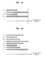
- FIG 4A shows examples for explaining how a sensor unit in FIGS. 2A to 2C controls the integration time for each line
- FIG. 4B shows an example for explaining how the sensor unit in FIGS. 2A to 2C controls the integration time for each line
- FIG. 5A shows an image which has a narrow dynamic range in a dark area
- FIG. 5B shows an image which has a narrow dynamic range in a light area
- FIG. 6 shows an image which has different integration times for individual lines
- FIG. 7 shows an image obtained after an interpolation filtering is applied, according to an exemplary embodiment of the present invention.
- FIG. 8A is a flowchart illustrating a method of improving a dynannc range of an image, according to an exemplary embodiment of the present invention.
- FIG. 8B is a flowchart illustrating a method of improving a dynamic range of an image, according to another exemplary embodiment of the present invention.
- a dynamic range of an image is a luminance level of an image ranging from a light area to a dark area, which the image display device can represent.
- the dynamic range is adjusted by changing pixel values which indicate lightness (such as luminance) of an image.
- An image display device with a wider dynamic range can have more tonal variations.
- the present invention is for solving problems cased by a limited dynamic range of an image capture device which is not sufficient to fully represent a natural scene.
- a dynamic range is enhanced by adjusting the duration of integration time in a sensor unit to achieve different dynamic ranges.
- FIG. 2A is a block diagram of an apparatus 200 for improving a dynamic range of an image, according to an exemplary embodiment of the present invention.
- the apparatus 200 includes an input image creating unit 210, and an image processing unit 220.
- the input image creating unit 210 includes a lens 212, and a sensor unit 214.
- the input image creating unit 210 creates an input image using a sensor that has different durations of integration time for individual lines when light is incident to the sensor, and outputs the created image to the image processing unit 220.
- the lens 212 focuses the light passing through the lens 212 in the direction of the sensor unit 214 which senses the light.
- the sensor unit 214 senses the light focused on it by the lens 212, converts the light into electronic signals to create an input image, and outputs the image to the image processing unit 220.
- the sensor unit 214 includes a charge-coupled device (CCD) sensor or a complementary metal-oxide-semiconductor (CMOS) sensor which is composed of n x M pixels, collects the light that is incident to the pixels, and converts the light into the electronic signals. Individual information obtained by each pixel of the sensor unit 214 corresponds to individual pixel of the image.
- the sensor unit 214 can control the duration of integration time on the basis of a line of the pixel to control the duration of integration time for each line of the image.
- the durations of integration time for lines of the sensor unit 214 are previously set to differ from each other. Since an image capture device which is placed in a fixed location or constant environment has a certain optimum duration of integration time, a sensor unit with a fixed duration of integration time for each line is used for such an image capture device.
- the image processing unit 220 processes the input image created by the input image creating unit 210 and outputs an interpolated image. According to the present exemplary embodiment, the image processing unit 220 processes the input image by applying interpolation filtering to the image in consideration of correlation between a current line and neighboring lines which have different durations of integration time so that the apparatus 200 can improve the limited dynamic range to a wider dynamic range by using the information including a different dynamic range.
- FIG. 2B is a block diagram of an apparatus 200 for improving a dynamic range of an image, according to another exemplary embodiment of the present invention.
- the apparatus 200 includes an input image creating unit 230, and an image processing unit 220.
- the input image creating unit 230 includes a lens 212, a sensor unit 234, and an integration time controlling unit 236.
- the structures and functions of the lens 212 and the image processing unit 220 are the same as those of the lens 212 and the image processing unit 220 in FIG. 2A .
- the input image processing unit 230 sets the optimum duration of integration time using characteristics of an input image so as to set the durations of integration time for individual lines, creates an input image, and outputs the image to the image processing unit 220.
- the sensor unit 234 converts the light incident from the lens 212 into electronic signals, and outputs the signals to the integration time controlling unit 234 and the image processing unit 220. Although the function of the sensor unit 234 is similar to the sensor unit 214 in FIG. 2A , the durations of integration time of the sensor unit 234 can be variably controlled. The image initially obtained by the sensor unit 234 is used to calculate the optimum duration of integration time.
- the integration time controlling unit 236 calculates the duration of integration time of the sensor unit 234 which senses the light, and outputs the calculated duration of integration time to the sensor unit 234 and the image processing unit 220. Since the duration of integration time has to be set for each line, the integration time controlling unit 236 needs to determine the duration of integration time for each line.
- the characteristics of the initial image obtained by the sensor unit 234 are analyzed and the durations of integration time are controlled based on the characteristics. Since the characteristics of the initial image have to be analyzed based on the dynamic range when the duration of integration time of the sensor unit 234 is constant, the initial image which is obtained before the duration of integration time for each line of the sensor unit 234 is set should be used.
- FIG. 2C is a block diagram of an apparatus 200 for improving a dynamic range of an image, according to another exemplary embodiment of the present invention.
- the apparatus 200 includes an input image creating unit 240, and an image processing unit 250.
- the input image creating unit 230 includes a lens 212, a sensor unit 234, and an integration time controlling unit 246.
- the structures and functions of the lens 212 and the sensor unit 234 are the same as those of the lens 212 and the sensor unit 234 in FIG. 2B .
- the input image creating unit 240 creates an initial image and outputs it to the image processing unit 250, and creates an input image and outputs it to the image processing unit 250.
- the input image has a differently set integration time for each line which is received from the image processing unit 250.
- the integration time controlling unit 246 receives the integration time, which is differently controlled for individual lines, from the image processing unit 250 and controls the integration time of each line of the sensor unit 234.
- the image processing unit 250 calculates the optimal duration of integration time for each line using the initial image obtained by the sensor unit 234, and outputs the optimal duration of integration time to the integration time controlling unit 246 of the input image creating unit 240. Additionally, the image processing unit 250 processes the input image created by the input image creating unit 210 and outputs an interpolated image, like the image processing unit 220 in FIGS. 2A or 2B .
- the integration time controlling unit 236 determines the duration of integration time for each line of the sensor unit 234, and controls the integration time for the sensor unit 234.
- the image processing unit 250 determines the duration of integration time for each line of the sensor unit 234, and the integration time controlling unit 246 controls the integration time for the sensor unit 234 based on the integration time determined by the image processing unit 250.
- the amount of light incident to a sensor is proportional to the duration of integration time.
- the amount of light incident to the sensor can be increased so that a dynamic range of a dark area of an image can be enhanced.
- the shorter integration time results in a lesser amount of the light incident to the sensor, which improves the dynamic range of a bright area of an image so that the image with more details in the bright part can be obtained.
- the dynamic range of a dark area decreases, which causes less subtle tonal graduations.
- the duration of integration time needs to be shortened, and when the image is too dark, the duration of integration time is controlled to be increased so as to collect sufficient light.
- FIG. 3A shows an actual dynamic range 102 of an object to be captured and a dynamic range 112 of an image capture device.
- the actual dynamic range 102 of the object present in a natural scene ranges from X to Y
- the dynamic range 112 of the image capture device varies from X' to Y'.
- the object to be captured has significant information only about its bright and dark ranges, not about the mid-tone range. Since the dynamic range 112 of the image capture device cannot cover all the dynamic range 102 of the object, the image capture device cannot fully represent the object and consequently has limited tonal graduations.
- FIG. 3B shows a dynamic range of an image capture device when it has a longer integration time.
- the image capture device can have the dynamic range varying from X", which is close to X of the dynamic range 102 of the object, by increasing the integration time. Hence, the entire information of the light range 332 which cannot be obtained in FIG. 3A can be achieved.
- the dynamic range 112 of the image capture device is fixed, Y' is accordingly moved to Y" and the distance between Y' and Y" is the same as the distance between X' and X".
- the light area is saturated in proportion to the amount of the incident light, and thus more specified information of the light area can be obtained.
- FIG. 3C shows a dynamic range 112 of the image capture device when it has a short integration time.
- the image capture device can obtain the information about the dark range up to Y"' which is close to Y of the dynamic range of the object. Therefore, the entire information of the dark area 332 can be obtained, while it cannot be obtained in FIG. 3A . Since the dynamic range 112 of the image capture device is fixed, X is moved to X"' the same distance as Y is moved to Y"'. Thus, less light is incident, and consequently specified information of the darker area can be achieved.
- FIG. 3D shows a dynamic range of the image capture device when interpolation filtering is performed using short and long lines, according to an exemplary embodiment of the present invention.
- the insufficient dynamic range of each case can be compensated for, and thus the details of dark and light areas can be represented.
- the dynamic range 112 of the image capture device is fixed, the information of the light and dark areas can be displayed using the pieces of information 322 and 332 which are obtained when the integration time is long and when it is short.
- luminance values of the information 322 and 332 of the light and dark areas are placed closer to each other in the middle luminance range, compared to the luminance values of the actual object to be captured, it is efficient to represent the image having more details in the dark and light areas when the image does not have significant information in the mid-tone range.
- the dark area of the object present in a natural scene with a wider dynamic range which the conventional image capture device cannot represent can be represented in detail, and an excessively light image which is difficult to be recognized can be prevented.
- the integration time is not set for the entire image, but is set for individual lines, and correlation between a current line and neighboring lines and such differently set integration times are used to obtain a wider dynamic range.
- the integration time controlling unit 236 or the image processing unit 250 determines the integration time for each line using the characteristics of the initial image.
- the usable characteristics of the initial image may include grayscale distribution, the amount of noise, and the intensity of movement of an object to be captured.
- the duration of integration time for each line, and how many lines will have different lengths may be determined.
- FIG. 4A shows examples for explaining how the sensor unit 214 or 234 in FIGS. 2A to 2C controls the integration time for each line.
- the odd numbered and even numbered lines of the sensor unit 214 or 234 have different integration times. Since the odd numbered lines have shorter integration times than the even numbered lines, the image is darker than when the integration time is longer, and since the even numbered lines have longer integration times than the odd numbered lines, the image is lighter than when the integration time is shorter. Thus, the odd numbered lines are effective when too much light is incident to the sensor unit 214 or 234 and the image is excessively light, and the even numbered lines are effective when it is too dark to recognize the object.
- the lines having different integration time are at least one.
- the integration times can be set individually for the odd numbered lines and the even numbered lines, or, for example, the only one line of an image may have an integration time different from the other lines.
- FIG. 4B shows an example for explaining how the sensor unit 214 or 234 in FIGS. 2A to 2C controls the integration time for each line.
- FIG. 4B different integration times are set for every four neighboring lines repeatedly.
- image processing can be performed by applying interpolation filtering using different characteristics of dynamic ranges of the lines even when a plurality of lines have different integration times.
- the image processing unit 220 and 250 performs interpolation filtering on lines using correlation between the lines with different integration times.
- the correlation between ines is defined based on the characteristics and integration time of the input image.
- the interpolation filtering using the lines is performed using a vertical interpolation filter.
- a coefficient of the interpolation filter is decided based on the correlation between lines.
- the correlation between lines and the coefficient of the interpolation filter may be determined in consideration of characteristics of the input image, for example, the characteristics of dynamic range of the input image, whether noise is present in the input image, and whether a moving object is present in the input image.
- characteristics of the input image for example, the characteristics of dynamic range of the input image, whether noise is present in the input image, and whether a moving object is present in the input image.
- the coefficient of the interpolation fiter needs to be determined so that the resulting image after interpolation filtering is performed can be reasonably bright.
- the lines with a shorter integration time are more advantageous for presentation of details in a light area of an image, and the lines with a longer integration time are more beneficial to presentation of details in a dark area.
- the odd numbered lines have a shorter integration time and the even numbered lines have a longer integration time.
- the image processing units 220 and 250 enhance the details of both the light and dark areas by performing interpolation filtering based on correlation between the odd numbered lines and the even numbered lines.
- an even numbered line which has a wider dynamic range of a dark area is used for the interpolation filtering.
- the dynamic range of the dark area of the odd numbered line can be compensated for by using information about the dark area of the even numbered line.
- the odd numbered line which has a wider dynamic range of a light area is used for the interpolation filtering. That is, the dynamic range of the light area of the even numbered line can be compensated for by using information about the light area of the odd numbered line.
- the interpolation filtering is performed by adding a value obtained by multiplying the current pixel on the nth line by a certain weight and a value obtained by multiplying at least one of neighboring pixels which have a different integration time than the current pixel by a certain weight.
- a value of the current pixel on the nth line is x
- a value of a neighboring pixel on an (n+1)th line is y
- a value of a neighboring pixel on an (n-1)th line is z
- coefficients for the neighboring lines are set based on the integration time and a dynamic range of an image, and these are applied as weights to the pixel values used for interpolation filtering.
- FIG. 5A shows an image which has a narrow dynamic range in a dark area.
- FIG. 5B shows an image which has a narrow dynamic range in a light area.
- FIG. 6 shows an image which has different integration times for individual lines.
- the image is produced by an image dynamic range improving apparatus which includes sensors having odd numbered lines with a longer integration time and even numbered lines with a shorter integration time, and image processing has not yet been performed on the image.
- the image in FIG. 6 is created by capturing the same image as shown in FIG. 5A or 5B using individual lines that have different integration times. Therefore, the odd numbered lines have a shorter integration time so that details in the light area of an image can be fully shown, and the even numbered lines have a longer integration time so that more grayscales in the dark area can be displayed.
- FIG. 7 shows an image obtained after interpolation filtering is applied, according to an exemplary embodiment of the present invention.
- a vertical interpolation filter of [0.25, 0.5, 0.25] is used. Coefficients of the interpolation filter are set to maintain an average brightness of the image. Since the integration times are set differently for the odd numbered lines and the even numbered lines, a three tap filter is used. Since the integration times between the odd numbered lines are identical to each other and the integration times between the even numbered lines are identical to each other, the first and third coefficents of the interpolation filter are the same as each other.
- the image of FIG. 7 is produced by performing the interpolation filtering using the odd numbered lines and the even numbered lines of the image in FIG. 6 , and the general grayscale representation is enhanced. While the desks and the objects on the desks in the image illustrated in FIG. 5A cannot be identified since the dynamic range of the darker area is not sufficient, the desks and objects on the desks in the corresponding area of the image in FIG. 7 are shown clearly. Also, while the windows, the window blinds, and the window frames in FIG. 5B are not identified due to excessive light, details around the windows in the corresponding area of the image in FIG. 7 are definitely shown.
- the characteristics of the wider dynamic range of the light area of the image with the shorter integration time and the characteristics of the narrower dynamic range of the dark area of the image with the longer integration time are combined, and thus, the general grayscale representation of the image is enhanced.
- Controlling the length of the integration times so as to enhance grayscale representation can be beneficially used for other image processing methods. Since the integration time closely correlates with the brightness of an image, the present invention can be applied to any cases affected by the brightness.
- the integration times of individual lines are differently controlled so that the movement blurring can be prevented as well as enhancing the grayscale representation.
- the lines with a shorter integration time are effective in preventing the movement blurring and the lines with a longer integration time are beneficial for improving the grayscale representation. Accordingly, by applying interpolation filtering using these lines, an image with darker areas having a rich grayscale representation and less movement blurring can be produced.
- the integration time When the integration time is shorter, an image may be darker and more noises can occur in the image. If the integration time is increased to prevent the noises, in lighter areas of the image, the light may become saturated. Thus, the integration time may be controlled so as to be less affected by the noises and prevent excessive light exposure.
- the integration times for individual lines are controlled so that lines with a longer integration time can prevent the noises and lines with a shorter integration time can enhance the lighter areas of the image in which the light saturates.
- FIGS. 8A and 8B a method of improving a dynamic range of an image will now be described with reference to FIGS. 8A and 8B .
- FIG. 8A is a flowchart illustrating a method of improving a dynamic range of an image, according to an exemplary embodiment of the present invention.
- integration times of individual lines of a sensor unit are differently set.
- the integration times are determined in consideration of an environment where an image capture device is used.
- an input image is produced by the sensor unit which has different integration times set for individual lines.
- an interpolated image is produced by applying interpolation filtering to the input image created in operation 840 by using neighboring lines having different integration times.
- Coefficients of an interpolation filter are decided in consideration of a correlation between a current line and neighboring Ines having different integration times. The correlation is obtained based on image characteristics such as the integration times and dynamic ranges.
- FIG. 8B is a flowchart illustrating a method of improving a dynamic range of an image, according to another exemplary embodiment of the present invention.
- an initial image is obtained by a sensor unit.
- an input image is created by the sensor which has different integration times for individual lines.
- interpolation filtering is performed to the input image by using neighboring lines with different integrating times and an interpolated image is produced. Coefficients of an interpolation filter are obtained in consideration of the set integration times and a dynamic range of the input image.
- the exemplary embodiments of the present invention can be written as computer programs and can be implemented in general-use digital computers that execute the programs using a computer readable recording medium.
- Examples of the computer readable recording medium include magnetic storage media (e.g., ROM, floppy disks, hard disks, etc.), and optical recording media (e.g., CD-ROMs, or DVDs).
Landscapes
- Engineering & Computer Science (AREA)
- Multimedia (AREA)
- Signal Processing (AREA)
- Image Processing (AREA)
- Studio Devices (AREA)
- Transforming Light Signals Into Electric Signals (AREA)
Claims (11)
- Verfahren zum Verbessern eines dynamischen Bereichs eines Bildes, das von einer Sensoreinheit (234) einer Bilderfassungseinheit erhalten wird, das Verfahren umfassend:Erzeugen eines Eingabebildes, das eine Vielzahl von Zeilen hat und verschiedene Integrationszeiten für individuelle Zeilen hat, durch Verwenden der Sensoreinheit (234) ; undErzeugen eines interpolierten Bildes mittels Anwenden von Interpolationsfiltern auf das Eingabebild durch Verwenden von benachbarten Zeilen einer aktuellen Zeile und der aktuellen Zeile, wobei die benachbarten Zeilen Integrationszeiten haben, die sich von der aktuellen Zeile unterscheiden,wobei Erzeugen des interpolierten Bildes weiterhin umfasst:Bestimmen von Filterkoeffizienten des Interpolationsfilterns basierend auf den Integrationszeiten und den Charakteristiken des Eingabebildes;wobei Erzeugen des Eingabebildes umfasst:Erhalten eines Anfangsbildes durch Verwenden der Sensoreinheit (234);Setzen der verschiedenen Integrationszeiten für die individuellen Zeilen der Sensoreinheit (234) durch Verwenden von Charakteristiken des Anfangsbildes, wobei die Charakteristiken des Eingabebildes sind, ob ein bewegtes Objekt in dem Eingabebild vorhanden ist; und die Charakteristiken des Anfangsbildes wenigstens eines sind von: ob Rauschen in dem Anfangsbild vorhanden ist, ob ein bewegtes Objekt in dem Anfangsbild vorhanden ist, sowie der dynamische Bereich des Anfangsbildes; undErzeugen des Eingabebildes durch Verwenden der Sensoreinheit (234), welche die verschiedenen Integrationszeiten für individuelle Zeilen hat.
- Verfahren gemäß Anspruch 1, wobei beim Erzeugen des Eingabebildes, vorher die Integrationszeiten der Sensoreinheit (234) für die individuellen Zeilen bestimmt werden.
- Verfahren gemäß Anspruch 1, wobei das Interpolationsfiltern verwendet wird, um eine gewichtete Summe zu berechnen, die erhalten wird durch Multiplizieren eines Pixelwertes eines Pixels in der aktuelle Zeile mit einem bestimmten Gewicht und Multiplizieren von wenigstens einem Pixelwert von Pixeln in jeder der benachbarten Zeilen mit einem anderen Gewicht und Zusammenaddieren der multiplizierten Pixelwerte.
- Verfahren gemäß Anspruch 2, wobei beim Setzen der Integrationszeiten, die Integrationszeiten für wenigstens eine der Zeilen individuell gesteuert werden basierend auf wenigstens einem aus: einem dynamischen Bereich des Anfangsbildes, einem Rauschpegel des Anfangsbildes und einer Menge von Bewegungsunschärfe, die auftritt, wenn es Bewegung im Anfangsbild gibt.
- Verfahren gemäß Anspruch 1, wobei die Filterkoeffizienten bestimmt werden basierend auf wenigstens einem aus: den Integrationszeiten für die Zeilen und dem dynamischen Bereich des Eingabebildes.
- Vorrichtung (200) zum Verbessern eines Bild-dynamischen Bereichs eines Bildes, die Vorrichtung (200) umfassend:eine Eingabebilderzeugungseinheit (230, 240), die ein Eingabebild erzeugt durch Umwandeln von Licht in elektronische Signale, wobei das Licht auf individuelle Zeilen für eine Periode einer Integrationszeit einfallend ist, die für jede der Zeilen unterschiedlich ist; undeine Bildverarbeitungseinheit (220, 250), die Interpolationsfiltern auf dem Eingabebild durchführt, durch Verwenden einer aktuellen Zeile und benachbarter Zeilen der aktuellen Zeile, wobei die benachbarten Zeilen Integrationszeiten haben, die von der aktuellen Zeile verschieden sind, und die ein interpoliertes Bild erzeugt;wobei die Bildverarbeitungseinheit (220, 250) umfasst:eine Interpolationsfiltererzeugungseinheit die Interpolationsfilterkoeffizienten des Interpolationsfilterns steuert, basierend auf Integrationszeiten und Charakteristiken des Eingabebildes, undeine Interpolationsfiltereinheit, die das Interpolationsfiltern unter Verwendung der Interpolationsfilter durchführt;wobei die Eingabebilderzeugungseinheit (230, 240) umfasst:eine Sensoreinheit (234), die ein Anfangsbild durch Umwandeln des einfallenden Lichts in elektronische Signale erhält; undeine Integrationszeitsteuereinheit (236, 246), die individuell die Integrationszeiten für die Zeilen der Sensoreinheit (234) steuert durch Verwenden von Charakteristiken des Anfangsbildes, das von der Sensoreinheit (234) erhalten wird, wobei die Charakteristiken des Eingabebildes sind, ob ein bewegtes Objekt in dem Eingabebild vorhanden ist; und die Charakteristiken des Anfangsbildes wenigstens eines sind von: ob Rauschen in dem Anfangsbild vorhanden ist, ob ein bewegtes Objekt in dem Anfangsbild vorhanden ist, sowie der dynamische Bereich des Anfangsbildes;wobei die Sensoreinheit (234) ausgebildet ist, verschiedene Integrationszeiten zu setzen.
- Vorrichtung (200) gemäß Anspruch 6, wobei das Interpolationsfiltern verwendet wird, um eine gewichtete Summe zu berechnen, die erhalten wird durch Multiplizieren eines Pixelwertes eines Pixels in der aktuelle Zeile und wenigstens eines Pixelwertes von Pixeln in jeder der benachbarten Zeilen mit einem bestimmten Gewicht und Zusammenaddieren der multiplizierten Pixelwerte..
- Vorrichtung (200) gemäß Anspruch 6, wobei die Integrationszeitsteuereinheit (236, 246) wenigstens eine der Integrationszeiten der Zeilen unterschiedlich steuert und setzt, basierend auf wenigstens einem aus: einem dynamischen Bereich des Anfangsbildes, einem Rauschpegel des Anfangsbildes und einer Menge von Bewegungsunschärfe, die auftritt, wenn es Bewegung im Anfangsbild gibt.
- Vorrichtung (200) gemäß Anspruch 6, wobei die Bildverarbeitungseinheit (220, 250) wenigstens eine der Integrationszeiten der Zeilen unterschiedlich steuert und setzt, basierend auf wenigstens einem aus: einem dynamischen Bereich des Anfangsbildes, einem Rauschpegel des Anfangsbildes und einer Menge von Bewegungsunschärfe, die auftritt, wenn es Bewegung im Anfangsbild gibt, und übermittelt die individuell gesteuerten Integrationszeiten für die Zeilen der Sensoreinheit (234) durch Verwenden von Charakteristiken des Anfangsbildes, das von der Eingabebilderzeugungseinheit (230, 240) erzeugt wird .
- Vorrichtung (200) gemäß Anspruch 6, wobei die Interpolationsfiltererzeugungseinheit die Interpolationsfilterkoeffizienten bestimmt, basierend auf wenigstens einem von: den Integrationszeiten für Zeilen und einem dynamischen Bereich des Eingabebildes.
- Ein Computer-lesbares Aufzeichnungsmedium, das ein Computerprogramm darauf enthält zum Ausführen des Verfahrens zur Verbesserung eines dynamischen Bereichs eines Bild gemäß einem der Ansprüche 1 - 5.
Applications Claiming Priority (2)
| Application Number | Priority Date | Filing Date | Title |
|---|---|---|---|
| KR1020070064613A KR101380615B1 (ko) | 2007-06-28 | 2007-06-28 | 영상 동적 범위 향상 방법 및 장치 |
| PCT/KR2008/000648 WO2009002000A1 (en) | 2007-06-28 | 2008-02-04 | Method and apparatus for improving dynamic range of image |
Publications (3)
| Publication Number | Publication Date |
|---|---|
| EP2163086A1 EP2163086A1 (de) | 2010-03-17 |
| EP2163086A4 EP2163086A4 (de) | 2010-09-29 |
| EP2163086B1 true EP2163086B1 (de) | 2013-10-30 |
Family
ID=40159917
Family Applications (1)
| Application Number | Title | Priority Date | Filing Date |
|---|---|---|---|
| EP08712300.6A Not-in-force EP2163086B1 (de) | 2007-06-28 | 2008-02-04 | Verfahren und vorrichtung zur verbesserung des dynamikumfangs eines bildes |
Country Status (6)
| Country | Link |
|---|---|
| US (1) | US8456555B2 (de) |
| EP (1) | EP2163086B1 (de) |
| JP (1) | JP5214991B2 (de) |
| KR (1) | KR101380615B1 (de) |
| CN (1) | CN101335821A (de) |
| WO (1) | WO2009002000A1 (de) |
Families Citing this family (16)
| Publication number | Priority date | Publication date | Assignee | Title |
|---|---|---|---|---|
| JP2009010836A (ja) * | 2007-06-29 | 2009-01-15 | Panasonic Corp | 撮像装置、撮像方法、プログラム、および集積回路 |
| CN101588515B (zh) * | 2009-06-30 | 2010-10-27 | 北京空间机电研究所 | 线阵遥感ccd相机动态范围自适应实时调节方法 |
| KR101643319B1 (ko) | 2010-01-11 | 2016-07-27 | 삼성전자주식회사 | 하이 다이나믹 레인지 영상을 획득하는 장치 및 그 방법 |
| JP5644544B2 (ja) * | 2011-01-27 | 2014-12-24 | ソニー株式会社 | 発光強度測定装置 |
| JP5947507B2 (ja) * | 2011-09-01 | 2016-07-06 | キヤノン株式会社 | 撮像装置及びその制御方法 |
| US8913153B2 (en) | 2011-10-06 | 2014-12-16 | Aptina Imaging Corporation | Imaging systems and methods for generating motion-compensated high-dynamic-range images |
| US9172889B2 (en) * | 2012-02-09 | 2015-10-27 | Semiconductor Components Industries, Llc | Imaging systems and methods for generating auto-exposed high-dynamic-range images |
| JP5634420B2 (ja) | 2012-02-24 | 2014-12-03 | 株式会社東芝 | 画像処理装置及び固体撮像装置 |
| KR102003815B1 (ko) * | 2012-03-23 | 2019-10-01 | 에스케이하이닉스 주식회사 | 이미지 센서 및 그 동작 방법 |
| US8946614B2 (en) | 2012-03-23 | 2015-02-03 | SK Hynix Inc. | Image sensor with wide dynamic range and method of operating the same including one or more first and second column groups of pixels alternatively arranged |
| US9338372B2 (en) | 2012-09-19 | 2016-05-10 | Semiconductor Components Industries, Llc | Column-based high dynamic range imaging systems |
| FR2998752B1 (fr) * | 2012-11-27 | 2016-01-01 | E2V Semiconductors | Procede de capture d'image avec un temps d'integration tres court |
| JP6417197B2 (ja) | 2014-11-27 | 2018-10-31 | キヤノン株式会社 | 固体撮像装置 |
| JP6282303B2 (ja) | 2015-05-29 | 2018-02-21 | キヤノン株式会社 | 撮像素子および撮像装置 |
| WO2020062269A1 (zh) * | 2018-09-30 | 2020-04-02 | 深圳配天智能技术研究院有限公司 | 图像传感器、获取图像的方法、视觉系统及存储介质 |
| CN120856845B (zh) * | 2025-09-09 | 2026-01-13 | 杭州汇萃智能科技有限公司 | 基于智能cmos图像传感器的空间滤波方法、系统及介质 |
Citations (1)
| Publication number | Priority date | Publication date | Assignee | Title |
|---|---|---|---|---|
| US20030174234A1 (en) * | 2000-04-13 | 2003-09-18 | Tetsujiro Kondo | Imaging device and imaging method |
Family Cites Families (14)
| Publication number | Priority date | Publication date | Assignee | Title |
|---|---|---|---|---|
| DE3615342A1 (de) * | 1985-05-08 | 1986-11-13 | Fuji Photo Film Co., Ltd., Minami-Ashigara, Kanagawa | Farbbildsensor |
| US6611287B1 (en) * | 1997-11-28 | 2003-08-26 | Sony Corporation | Camera signal processing apparatus and camera signal processing method |
| US7193652B2 (en) * | 1999-08-17 | 2007-03-20 | Applied Vision Systems, Inc. | Dynamic range video recording and playback system and method |
| US6950469B2 (en) * | 2001-09-17 | 2005-09-27 | Nokia Corporation | Method for sub-pixel value interpolation |
| JP2004064165A (ja) * | 2002-07-25 | 2004-02-26 | Hitachi Ltd | 撮像装置および撮像方法 |
| US7830435B2 (en) * | 2003-09-03 | 2010-11-09 | Eastman Kodak Company | Image sensor and image capture system with extended dynamic range |
| US7446812B2 (en) * | 2004-01-13 | 2008-11-04 | Micron Technology, Inc. | Wide dynamic range operations for imaging |
| US7336846B2 (en) * | 2004-03-02 | 2008-02-26 | Kabushiki Kaisha Toshiba | Method and apparatus for processing images using black character substitution |
| JP2006033381A (ja) | 2004-07-15 | 2006-02-02 | Canon Inc | 撮像装置及び制御方法 |
| US7880785B2 (en) * | 2004-07-21 | 2011-02-01 | Aptina Imaging Corporation | Rod and cone response sensor |
| JP4689620B2 (ja) * | 2004-11-02 | 2011-05-25 | パナソニック株式会社 | イメージセンサ |
| KR100597651B1 (ko) * | 2005-01-24 | 2006-07-05 | 한국과학기술원 | 이미지 센서, 실제 이미지를 전기적 신호로 바꾸는 장치 및 그 방법 |
| US7554588B2 (en) * | 2005-02-01 | 2009-06-30 | TransChip Israel, Ltd. | Dual exposure for image sensor |
| US7557832B2 (en) * | 2005-08-12 | 2009-07-07 | Volker Lindenstruth | Method and apparatus for electronically stabilizing digital images |
-
2007
- 2007-06-28 KR KR1020070064613A patent/KR101380615B1/ko not_active Expired - Fee Related
- 2007-11-16 US US11/941,202 patent/US8456555B2/en active Active
-
2008
- 2008-02-04 WO PCT/KR2008/000648 patent/WO2009002000A1/en not_active Ceased
- 2008-02-04 EP EP08712300.6A patent/EP2163086B1/de not_active Not-in-force
- 2008-02-08 JP JP2008029250A patent/JP5214991B2/ja not_active Expired - Fee Related
- 2008-02-20 CN CNA2008100096780A patent/CN101335821A/zh active Pending
Patent Citations (1)
| Publication number | Priority date | Publication date | Assignee | Title |
|---|---|---|---|---|
| US20030174234A1 (en) * | 2000-04-13 | 2003-09-18 | Tetsujiro Kondo | Imaging device and imaging method |
Also Published As
| Publication number | Publication date |
|---|---|
| KR20090000503A (ko) | 2009-01-07 |
| EP2163086A4 (de) | 2010-09-29 |
| EP2163086A1 (de) | 2010-03-17 |
| US20090002525A1 (en) | 2009-01-01 |
| US8456555B2 (en) | 2013-06-04 |
| JP2009010917A (ja) | 2009-01-15 |
| CN101335821A (zh) | 2008-12-31 |
| WO2009002000A1 (en) | 2008-12-31 |
| JP5214991B2 (ja) | 2013-06-19 |
| KR101380615B1 (ko) | 2014-04-14 |
Similar Documents
| Publication | Publication Date | Title |
|---|---|---|
| US8456555B2 (en) | Method and apparatus for improving dynamic range of image | |
| EP3847800B1 (de) | Automatische belichtung von bildsensoren mit hohem dynamikbereich mit räumlich gemultiplexter belichtung | |
| JP3801126B2 (ja) | 撮像装置,撮像装置の画像出力方法,およびコンピュータプログラム | |
| EP2216987B1 (de) | Bilderfassungsvorrichtung und Steuerverfahren dafür | |
| JP5083046B2 (ja) | 撮像装置及び撮像方法 | |
| US8483507B2 (en) | Image sensing apparatus and image processing method | |
| KR102145201B1 (ko) | 이미지의 동적 범위 향상을 위한 방법 및 장치 | |
| CN103854259B (zh) | 图像处理设备以及处理图像的方法 | |
| US8619156B2 (en) | Image capturing system and method of controlling the same utilizing exposure control that captures multiple images of different spatial resolutions | |
| US20080259181A1 (en) | Imaging apparatus, imaging method, integrated circuit, and storage medium | |
| US8023763B2 (en) | Method and apparatus for enhancing image, and image-processing system using the same | |
| CN102025918A (zh) | 图像处理装置、成像设备、图像处理方法和程序 | |
| US8526736B2 (en) | Image processing apparatus for correcting luminance and method thereof | |
| JP4273428B2 (ja) | 画像処理装置、画像処理方法、画像処理方法のプログラム及び画像処理方法のプログラムを記録した記録媒体 | |
| JP6786273B2 (ja) | 画像処理装置、画像処理方法、及びプログラム | |
| JP4999871B2 (ja) | 撮像装置およびその制御方法 | |
| CN101627408A (zh) | 图像信号处理装置、图像信号处理程序、图像信号处理方法 | |
| JP2008206111A (ja) | 撮影装置及び撮影方法 | |
| JP6912869B2 (ja) | 画像処理装置、画像処理プログラム、画像処理方法 | |
| US20140168464A1 (en) | Image processing apparatus and image processing method | |
| JP4414289B2 (ja) | コントラスト強調撮像装置 | |
| JP2009296179A (ja) | 画像処理装置及び画像処理方法、並びに、撮像装置及び撮像方法 | |
| KR100813620B1 (ko) | 명암대비 보정장치 및 보정방법 | |
| JP2008306326A (ja) | 画像処理装置および画像処理方法 | |
| CN119515749A (zh) | 图像处理方法、装置、计算机可读存储介质及电子设备 |
Legal Events
| Date | Code | Title | Description |
|---|---|---|---|
| PUAI | Public reference made under article 153(3) epc to a published international application that has entered the european phase |
Free format text: ORIGINAL CODE: 0009012 |
|
| 17P | Request for examination filed |
Effective date: 20091223 |
|
| AK | Designated contracting states |
Kind code of ref document: A1 Designated state(s): AT BE BG CH CY CZ DE DK EE ES FI FR GB GR HR HU IE IS IT LI LT LU LV MC MT NL NO PL PT RO SE SI SK TR |
|
| AX | Request for extension of the european patent |
Extension state: AL BA MK RS |
|
| A4 | Supplementary search report drawn up and despatched |
Effective date: 20100826 |
|
| DAX | Request for extension of the european patent (deleted) | ||
| 17Q | First examination report despatched |
Effective date: 20110916 |
|
| RAP1 | Party data changed (applicant data changed or rights of an application transferred) |
Owner name: SAMSUNG ELECTRONICS CO., LTD. |
|
| GRAP | Despatch of communication of intention to grant a patent |
Free format text: ORIGINAL CODE: EPIDOSNIGR1 |
|
| RIC1 | Information provided on ipc code assigned before grant |
Ipc: H04N 5/232 20060101AFI20130515BHEP Ipc: H04N 5/353 20110101ALI20130515BHEP Ipc: H04N 5/235 20060101ALI20130515BHEP |
|
| INTG | Intention to grant announced |
Effective date: 20130605 |
|
| GRAS | Grant fee paid |
Free format text: ORIGINAL CODE: EPIDOSNIGR3 |
|
| GRAA | (expected) grant |
Free format text: ORIGINAL CODE: 0009210 |
|
| AK | Designated contracting states |
Kind code of ref document: B1 Designated state(s): AT BE BG CH CY CZ DE DK EE ES FI FR GB GR HR HU IE IS IT LI LT LU LV MC MT NL NO PL PT RO SE SI SK TR |
|
| REG | Reference to a national code |
Ref country code: GB Ref legal event code: FG4D |
|
| REG | Reference to a national code |
Ref country code: CH Ref legal event code: EP |
|
| REG | Reference to a national code |
Ref country code: AT Ref legal event code: REF Ref document number: 638760 Country of ref document: AT Kind code of ref document: T Effective date: 20131115 |
|
| REG | Reference to a national code |
Ref country code: IE Ref legal event code: FG4D |
|
| REG | Reference to a national code |
Ref country code: DE Ref legal event code: R096 Ref document number: 602008028418 Country of ref document: DE Effective date: 20131224 |
|
| REG | Reference to a national code |
Ref country code: NL Ref legal event code: VDEP Effective date: 20131030 |
|
| REG | Reference to a national code |
Ref country code: AT Ref legal event code: MK05 Ref document number: 638760 Country of ref document: AT Kind code of ref document: T Effective date: 20131030 |
|
| REG | Reference to a national code |
Ref country code: LT Ref legal event code: MG4D |
|
| PG25 | Lapsed in a contracting state [announced via postgrant information from national office to epo] |
Ref country code: SE Free format text: LAPSE BECAUSE OF FAILURE TO SUBMIT A TRANSLATION OF THE DESCRIPTION OR TO PAY THE FEE WITHIN THE PRESCRIBED TIME-LIMIT Effective date: 20131030 Ref country code: NL Free format text: LAPSE BECAUSE OF FAILURE TO SUBMIT A TRANSLATION OF THE DESCRIPTION OR TO PAY THE FEE WITHIN THE PRESCRIBED TIME-LIMIT Effective date: 20131030 Ref country code: IS Free format text: LAPSE BECAUSE OF FAILURE TO SUBMIT A TRANSLATION OF THE DESCRIPTION OR TO PAY THE FEE WITHIN THE PRESCRIBED TIME-LIMIT Effective date: 20140228 Ref country code: NO Free format text: LAPSE BECAUSE OF FAILURE TO SUBMIT A TRANSLATION OF THE DESCRIPTION OR TO PAY THE FEE WITHIN THE PRESCRIBED TIME-LIMIT Effective date: 20140130 Ref country code: LT Free format text: LAPSE BECAUSE OF FAILURE TO SUBMIT A TRANSLATION OF THE DESCRIPTION OR TO PAY THE FEE WITHIN THE PRESCRIBED TIME-LIMIT Effective date: 20131030 Ref country code: HR Free format text: LAPSE BECAUSE OF FAILURE TO SUBMIT A TRANSLATION OF THE DESCRIPTION OR TO PAY THE FEE WITHIN THE PRESCRIBED TIME-LIMIT Effective date: 20131030 Ref country code: BE Free format text: LAPSE BECAUSE OF FAILURE TO SUBMIT A TRANSLATION OF THE DESCRIPTION OR TO PAY THE FEE WITHIN THE PRESCRIBED TIME-LIMIT Effective date: 20131030 Ref country code: FI Free format text: LAPSE BECAUSE OF FAILURE TO SUBMIT A TRANSLATION OF THE DESCRIPTION OR TO PAY THE FEE WITHIN THE PRESCRIBED TIME-LIMIT Effective date: 20131030 |
|
| PG25 | Lapsed in a contracting state [announced via postgrant information from national office to epo] |
Ref country code: LV Free format text: LAPSE BECAUSE OF FAILURE TO SUBMIT A TRANSLATION OF THE DESCRIPTION OR TO PAY THE FEE WITHIN THE PRESCRIBED TIME-LIMIT Effective date: 20131030 Ref country code: CY Free format text: LAPSE BECAUSE OF FAILURE TO SUBMIT A TRANSLATION OF THE DESCRIPTION OR TO PAY THE FEE WITHIN THE PRESCRIBED TIME-LIMIT Effective date: 20131030 Ref country code: ES Free format text: LAPSE BECAUSE OF FAILURE TO SUBMIT A TRANSLATION OF THE DESCRIPTION OR TO PAY THE FEE WITHIN THE PRESCRIBED TIME-LIMIT Effective date: 20131030 Ref country code: AT Free format text: LAPSE BECAUSE OF FAILURE TO SUBMIT A TRANSLATION OF THE DESCRIPTION OR TO PAY THE FEE WITHIN THE PRESCRIBED TIME-LIMIT Effective date: 20131030 |
|
| PG25 | Lapsed in a contracting state [announced via postgrant information from national office to epo] |
Ref country code: PT Free format text: LAPSE BECAUSE OF FAILURE TO SUBMIT A TRANSLATION OF THE DESCRIPTION OR TO PAY THE FEE WITHIN THE PRESCRIBED TIME-LIMIT Effective date: 20140228 |
|
| PG25 | Lapsed in a contracting state [announced via postgrant information from national office to epo] |
Ref country code: EE Free format text: LAPSE BECAUSE OF FAILURE TO SUBMIT A TRANSLATION OF THE DESCRIPTION OR TO PAY THE FEE WITHIN THE PRESCRIBED TIME-LIMIT Effective date: 20131030 |
|
| REG | Reference to a national code |
Ref country code: DE Ref legal event code: R097 Ref document number: 602008028418 Country of ref document: DE |
|
| PG25 | Lapsed in a contracting state [announced via postgrant information from national office to epo] |
Ref country code: CZ Free format text: LAPSE BECAUSE OF FAILURE TO SUBMIT A TRANSLATION OF THE DESCRIPTION OR TO PAY THE FEE WITHIN THE PRESCRIBED TIME-LIMIT Effective date: 20131030 Ref country code: RO Free format text: LAPSE BECAUSE OF FAILURE TO SUBMIT A TRANSLATION OF THE DESCRIPTION OR TO PAY THE FEE WITHIN THE PRESCRIBED TIME-LIMIT Effective date: 20131030 Ref country code: SK Free format text: LAPSE BECAUSE OF FAILURE TO SUBMIT A TRANSLATION OF THE DESCRIPTION OR TO PAY THE FEE WITHIN THE PRESCRIBED TIME-LIMIT Effective date: 20131030 Ref country code: PL Free format text: LAPSE BECAUSE OF FAILURE TO SUBMIT A TRANSLATION OF THE DESCRIPTION OR TO PAY THE FEE WITHIN THE PRESCRIBED TIME-LIMIT Effective date: 20131030 Ref country code: IT Free format text: LAPSE BECAUSE OF FAILURE TO SUBMIT A TRANSLATION OF THE DESCRIPTION OR TO PAY THE FEE WITHIN THE PRESCRIBED TIME-LIMIT Effective date: 20131030 |
|
| PLBE | No opposition filed within time limit |
Free format text: ORIGINAL CODE: 0009261 |
|
| STAA | Information on the status of an ep patent application or granted ep patent |
Free format text: STATUS: NO OPPOSITION FILED WITHIN TIME LIMIT |
|
| PG25 | Lapsed in a contracting state [announced via postgrant information from national office to epo] |
Ref country code: MC Free format text: LAPSE BECAUSE OF FAILURE TO SUBMIT A TRANSLATION OF THE DESCRIPTION OR TO PAY THE FEE WITHIN THE PRESCRIBED TIME-LIMIT Effective date: 20131030 Ref country code: DK Free format text: LAPSE BECAUSE OF FAILURE TO SUBMIT A TRANSLATION OF THE DESCRIPTION OR TO PAY THE FEE WITHIN THE PRESCRIBED TIME-LIMIT Effective date: 20131030 Ref country code: LU Free format text: LAPSE BECAUSE OF FAILURE TO SUBMIT A TRANSLATION OF THE DESCRIPTION OR TO PAY THE FEE WITHIN THE PRESCRIBED TIME-LIMIT Effective date: 20140204 |
|
| REG | Reference to a national code |
Ref country code: CH Ref legal event code: PL |
|
| 26N | No opposition filed |
Effective date: 20140731 |
|
| PG25 | Lapsed in a contracting state [announced via postgrant information from national office to epo] |
Ref country code: CH Free format text: LAPSE BECAUSE OF NON-PAYMENT OF DUE FEES Effective date: 20140228 Ref country code: LI Free format text: LAPSE BECAUSE OF NON-PAYMENT OF DUE FEES Effective date: 20140228 |
|
| REG | Reference to a national code |
Ref country code: DE Ref legal event code: R097 Ref document number: 602008028418 Country of ref document: DE Effective date: 20140731 |
|
| REG | Reference to a national code |
Ref country code: FR Ref legal event code: ST Effective date: 20141031 |
|
| REG | Reference to a national code |
Ref country code: IE Ref legal event code: MM4A |
|
| PG25 | Lapsed in a contracting state [announced via postgrant information from national office to epo] |
Ref country code: FR Free format text: LAPSE BECAUSE OF NON-PAYMENT OF DUE FEES Effective date: 20140228 Ref country code: IE Free format text: LAPSE BECAUSE OF NON-PAYMENT OF DUE FEES Effective date: 20140204 |
|
| PG25 | Lapsed in a contracting state [announced via postgrant information from national office to epo] |
Ref country code: SI Free format text: LAPSE BECAUSE OF FAILURE TO SUBMIT A TRANSLATION OF THE DESCRIPTION OR TO PAY THE FEE WITHIN THE PRESCRIBED TIME-LIMIT Effective date: 20131030 |
|
| PG25 | Lapsed in a contracting state [announced via postgrant information from national office to epo] |
Ref country code: MT Free format text: LAPSE BECAUSE OF FAILURE TO SUBMIT A TRANSLATION OF THE DESCRIPTION OR TO PAY THE FEE WITHIN THE PRESCRIBED TIME-LIMIT Effective date: 20131030 |
|
| PG25 | Lapsed in a contracting state [announced via postgrant information from national office to epo] |
Ref country code: BG Free format text: LAPSE BECAUSE OF FAILURE TO SUBMIT A TRANSLATION OF THE DESCRIPTION OR TO PAY THE FEE WITHIN THE PRESCRIBED TIME-LIMIT Effective date: 20131030 |
|
| PG25 | Lapsed in a contracting state [announced via postgrant information from national office to epo] |
Ref country code: GR Free format text: LAPSE BECAUSE OF FAILURE TO SUBMIT A TRANSLATION OF THE DESCRIPTION OR TO PAY THE FEE WITHIN THE PRESCRIBED TIME-LIMIT Effective date: 20140131 |
|
| PG25 | Lapsed in a contracting state [announced via postgrant information from national office to epo] |
Ref country code: HU Free format text: LAPSE BECAUSE OF FAILURE TO SUBMIT A TRANSLATION OF THE DESCRIPTION OR TO PAY THE FEE WITHIN THE PRESCRIBED TIME-LIMIT; INVALID AB INITIO Effective date: 20080204 Ref country code: TR Free format text: LAPSE BECAUSE OF FAILURE TO SUBMIT A TRANSLATION OF THE DESCRIPTION OR TO PAY THE FEE WITHIN THE PRESCRIBED TIME-LIMIT Effective date: 20131030 |
|
| PGFP | Annual fee paid to national office [announced via postgrant information from national office to epo] |
Ref country code: GB Payment date: 20220121 Year of fee payment: 15 Ref country code: DE Payment date: 20220120 Year of fee payment: 15 |
|
| REG | Reference to a national code |
Ref country code: DE Ref legal event code: R079 Ref document number: 602008028418 Country of ref document: DE Free format text: PREVIOUS MAIN CLASS: H04N0005232000 Ipc: H04N0023600000 |
|
| REG | Reference to a national code |
Ref country code: DE Ref legal event code: R119 Ref document number: 602008028418 Country of ref document: DE |
|
| GBPC | Gb: european patent ceased through non-payment of renewal fee |
Effective date: 20230204 |
|
| PG25 | Lapsed in a contracting state [announced via postgrant information from national office to epo] |
Ref country code: GB Free format text: LAPSE BECAUSE OF NON-PAYMENT OF DUE FEES Effective date: 20230204 |
|
| PG25 | Lapsed in a contracting state [announced via postgrant information from national office to epo] |
Ref country code: GB Free format text: LAPSE BECAUSE OF NON-PAYMENT OF DUE FEES Effective date: 20230204 Ref country code: DE Free format text: LAPSE BECAUSE OF NON-PAYMENT OF DUE FEES Effective date: 20230901 |