EP2163017B1 - Verfahren und vorrichtung zur abbildung von modulationssymbolen auf ressourcen in ofdm-systemen - Google Patents
Verfahren und vorrichtung zur abbildung von modulationssymbolen auf ressourcen in ofdm-systemen Download PDFInfo
- Publication number
- EP2163017B1 EP2163017B1 EP08765980.1A EP08765980A EP2163017B1 EP 2163017 B1 EP2163017 B1 EP 2163017B1 EP 08765980 A EP08765980 A EP 08765980A EP 2163017 B1 EP2163017 B1 EP 2163017B1
- Authority
- EP
- European Patent Office
- Prior art keywords
- seg
- region
- modulation symbols
- resource
- code blocks
- Prior art date
- Legal status (The legal status is an assumption and is not a legal conclusion. Google has not performed a legal analysis and makes no representation as to the accuracy of the status listed.)
- Active
Links
- 238000013507 mapping Methods 0.000 title claims description 60
- 238000000034 method Methods 0.000 title claims description 45
- 230000005540 biological transmission Effects 0.000 claims description 65
- 238000004891 communication Methods 0.000 claims description 15
- 238000012545 processing Methods 0.000 description 15
- 238000005562 fading Methods 0.000 description 9
- 239000000969 carrier Substances 0.000 description 7
- 230000001419 dependent effect Effects 0.000 description 7
- 230000008901 benefit Effects 0.000 description 6
- 125000004122 cyclic group Chemical group 0.000 description 6
- 238000005516 engineering process Methods 0.000 description 5
- 239000011159 matrix material Substances 0.000 description 5
- 230000011218 segmentation Effects 0.000 description 5
- 230000003247 decreasing effect Effects 0.000 description 4
- 238000001514 detection method Methods 0.000 description 4
- 238000013468 resource allocation Methods 0.000 description 3
- 230000008054 signal transmission Effects 0.000 description 3
- 230000001360 synchronised effect Effects 0.000 description 3
- 239000000945 filler Substances 0.000 description 2
- 238000003780 insertion Methods 0.000 description 2
- 230000037431 insertion Effects 0.000 description 2
- 230000007774 longterm Effects 0.000 description 2
- 238000005070 sampling Methods 0.000 description 2
- 238000012546 transfer Methods 0.000 description 2
- 239000013598 vector Substances 0.000 description 2
- 238000013459 approach Methods 0.000 description 1
- 230000015556 catabolic process Effects 0.000 description 1
- 238000012937 correction Methods 0.000 description 1
- 238000006731 degradation reaction Methods 0.000 description 1
- VJYFKVYYMZPMAB-UHFFFAOYSA-N ethoprophos Chemical compound CCCSP(=O)(OCC)SCCC VJYFKVYYMZPMAB-UHFFFAOYSA-N 0.000 description 1
- 230000002349 favourable effect Effects 0.000 description 1
- 238000012856 packing Methods 0.000 description 1
- 230000000135 prohibitive effect Effects 0.000 description 1
- 238000013139 quantization Methods 0.000 description 1
- 230000003595 spectral effect Effects 0.000 description 1
Images


Classifications
-
- H—ELECTRICITY
- H04—ELECTRIC COMMUNICATION TECHNIQUE
- H04L—TRANSMISSION OF DIGITAL INFORMATION, e.g. TELEGRAPHIC COMMUNICATION
- H04L27/00—Modulated-carrier systems
- H04L27/26—Systems using multi-frequency codes
- H04L27/2601—Multicarrier modulation systems
- H04L27/2602—Signal structure
-
- H—ELECTRICITY
- H04—ELECTRIC COMMUNICATION TECHNIQUE
- H04L—TRANSMISSION OF DIGITAL INFORMATION, e.g. TELEGRAPHIC COMMUNICATION
- H04L5/00—Arrangements affording multiple use of the transmission path
- H04L5/003—Arrangements for allocating sub-channels of the transmission path
- H04L5/0053—Allocation of signaling, i.e. of overhead other than pilot signals
-
- H—ELECTRICITY
- H04—ELECTRIC COMMUNICATION TECHNIQUE
- H04L—TRANSMISSION OF DIGITAL INFORMATION, e.g. TELEGRAPHIC COMMUNICATION
- H04L5/00—Arrangements affording multiple use of the transmission path
- H04L5/0001—Arrangements for dividing the transmission path
- H04L5/0003—Two-dimensional division
- H04L5/0005—Time-frequency
- H04L5/0007—Time-frequency the frequencies being orthogonal, e.g. OFDM(A), DMT
-
- H—ELECTRICITY
- H04—ELECTRIC COMMUNICATION TECHNIQUE
- H04L—TRANSMISSION OF DIGITAL INFORMATION, e.g. TELEGRAPHIC COMMUNICATION
- H04L5/00—Arrangements affording multiple use of the transmission path
- H04L5/0001—Arrangements for dividing the transmission path
- H04L5/0026—Division using four or more dimensions
-
- H—ELECTRICITY
- H04—ELECTRIC COMMUNICATION TECHNIQUE
- H04L—TRANSMISSION OF DIGITAL INFORMATION, e.g. TELEGRAPHIC COMMUNICATION
- H04L5/00—Arrangements affording multiple use of the transmission path
- H04L5/003—Arrangements for allocating sub-channels of the transmission path
- H04L5/0044—Arrangements for allocating sub-channels of the transmission path allocation of payload
- H04L5/0046—Determination of how many bits are transmitted on different sub-channels
-
- H—ELECTRICITY
- H04—ELECTRIC COMMUNICATION TECHNIQUE
- H04L—TRANSMISSION OF DIGITAL INFORMATION, e.g. TELEGRAPHIC COMMUNICATION
- H04L5/00—Arrangements affording multiple use of the transmission path
- H04L5/0091—Signaling for the administration of the divided path
- H04L5/0094—Indication of how sub-channels of the path are allocated
-
- H—ELECTRICITY
- H04—ELECTRIC COMMUNICATION TECHNIQUE
- H04W—WIRELESS COMMUNICATION NETWORKS
- H04W72/00—Local resource management
- H04W72/04—Wireless resource allocation
- H04W72/044—Wireless resource allocation based on the type of the allocated resource
- H04W72/0446—Resources in time domain, e.g. slots or frames
-
- H—ELECTRICITY
- H04—ELECTRIC COMMUNICATION TECHNIQUE
- H04W—WIRELESS COMMUNICATION NETWORKS
- H04W72/00—Local resource management
- H04W72/04—Wireless resource allocation
- H04W72/044—Wireless resource allocation based on the type of the allocated resource
- H04W72/0453—Resources in frequency domain, e.g. a carrier in FDMA
-
- H—ELECTRICITY
- H04—ELECTRIC COMMUNICATION TECHNIQUE
- H04L—TRANSMISSION OF DIGITAL INFORMATION, e.g. TELEGRAPHIC COMMUNICATION
- H04L27/00—Modulated-carrier systems
- H04L27/26—Systems using multi-frequency codes
- H04L27/2601—Multicarrier modulation systems
- H04L27/2602—Signal structure
- H04L27/26035—Maintenance of orthogonality, e.g. for signals exchanged between cells or users, or by using covering codes or sequences
Definitions
- the present invention relates to a method for mapping modulation symbols to resources in a communication system, and more specifically, a method for mapping modulation symbols into different resource regions in a communication system, and another method for mapping modulation symbols of multiple code blocks into resources in a communication system.
- Telecommunication enables transmission of data over a distance for the purpose of communication between a transmitter and a receiver.
- the data is usually carried by radio waves and is transmitted using a limited transmission resource. That is, radio waves are transmitted over a period of time using a limited frequency range.
- the information to be transmitted are first encoded and then modulated to generate multiple modulation symbols.
- the symbols are subsequently mapped into transmission resource.
- the transmission resource available for data transmission is segmented into a plurality of equal duration time and frequency slots, so called resource elements.
- a single resource element or multiple resource elements may be allocated for transmitting the data.
- a control signal may accompany the data to carry information regarding the allocation of the resource elements for the current data transmission. Therefore, when a receiver receives the data and the control signal, the receiver may derive the information regarding resource allocation used for data transmission from the control signal and decodes the received data using the derived information.
- each data transmission carries information bits of one or multiple transport blocks.
- the information bits in a transport block may be segmented into multiple code blocks.
- the process of dividing the information bits in a transport block into multiple code blocks is called code block segmentation. Due to the limited selection of code block sizes and the attempt to maximize packing efficiency during the code block segmentation, the multiple code blocks of a transport block may have different sizes.
- Each code block will be encoded, interleaved, rate matched, and modulated. Therefore, the data symbols for a transmission may consist of modulation symbols of multiple code blocks.
- MOTOROLA "Code Block Segmentation for LTE Channel Encoding", 3RD GENERATION PARTNERSHIP PROJECT (3GPP); TECHNICALSPECIFICATION GROUP (TSG) RADIO ACCESS NETWORK (RAN); WORKINGGROUP 1 (WG1), XX, XX, 12 February 2007 (2007-02-12), pages 1-5, XP002434167 , D1 relates to Code Block Segmentation for LTE Channel disclosing segmentation rules directing that a transmission block is segmented into plurality of code blocks of approximately same size, with at least one segment containing a certain amount of filler bits, i.e. containing smaller number of information bits than the others. Furthermore, that document teaches also to distribute the filler bits evenly over the segments.
- MOTOROLA "On Enabling Pipelining of Channel Coding Operations in LTE", 3GPP DRAFT; R1-072140 ENABLING CODING PIPELINING, 3RD GENERATION PARTNERSHIP PROJECT (3GPP), MOBILE COMPETENCE CENTRE ; 650, ROUTE DES LUCIOLES ; F-06921 SOPHIA-ANTIPOLIS CEDEX ; FRANCE, vol. RAN WG1, no. Kobe, Japan; 20070502, 2 May 2007 (2007-05-02 ) relates to the impact of channel estimation and successive interference cancellation (SIC) for MIMO detection on channel interleaving and the importance of separating the channel interleaving into bit and symbol interleaving functions. That document discloses in order to attain diversity benefits while maintaining efficient receiver operation that a combination of bit and symbol interleaving be adopted, and the span of the bit interleaving, if any, be restricted to a code block segment.
- SIC channel estimation and successive interference cancellation
- the difference between the DL and UL may be in the actual span of the symbol interleaving, which is left EES.
- a method for transmission may be provided to divide a transmission resource in a subframe into a plurality of equal duration resource elements in time and frequency domain, segregate the plurality of resource elements into one or a plurality of resource regions, modulate information to be transmitted to generate a sequence of modulation symbols at a transmitter, map the sequence of modulation symbols into the plurality of resource elements in the plurality of resource regions, and transmitting the modulation symbols via one or a plurality of antennas using the respective corresponding resource elements to a receiver.
- mapping of the modulation symbols in at least one resource region is independent of a certain control channel information that is carried in said time domain subframe
- mapping of the modulation symbols in at least another resource region i.e., second resource region
- the certain control channel information may be a control channel format indication.
- the method may further include interleaving the sequence of modulation symbols before mapping the modulation symbols into the resource elements.
- the sequence of modulation symbols may be sequentially mapped into resource elements within a plurality of multiplexing symbols in the resource regions starting from a multiplexing symbol having a smallest index in the time domain.
- a multiplexing symbol is an OFDM symbol in an Orthogonal Frequency Division Multiplex (OFDM) system.
- the mapping of the sequence of modulation symbols may start from the resource elements within the at least one first resource region. If the number of the modulation symbols is more than the resource elements in the at least one first resource region, the remaining modulation symbols may be mapped into the resource elements within the at least one second resource region.
- the multiplexing symbols may be mapped in each resource region in an increasing order starting from a multiplexing symbol having a smallest index in the time domain in that resource region.
- the modulation symbols within each multiplexing symbols may be interleaved in the frequency domain.
- the multiplexing symbols may be mapped in a decreasing order, and in the second resource region, the multiplexing symbols may be mapped in an increasing order.
- the multiplexing symbols may be mapped in an increasing order, and in the second resource region, the multiplexing symbols may be mapped in a decreasing order.
- the method may further include calculating the number of available resource elements in the at least one first resource region to obtain a first number, calculating the number of available resource elements in the at least one second resource region to obtain a second number, mapping the first number of modulation symbols into the resource elements within the at least one first resource region, and mapping the second number of modulation symbols into the resource elements within the at least one second resource region.
- the method may further include transmitting a control channel signal carrying said certain control channel information via the transmitter to the receiver, decoding at the receiver the control channel signal to derive said certain control channel information, determining which resource elements within the at least one second resource region are used for the transmission of the modulation symbols, collecting the modulation symbols transmitted in a resource region selected from among the at least one first resource region to generate a first data packet, decoding the first data packet, determining whether the first data packet decodes, and if the decoding of the first data packet fails, recursively collecting the modulation symbols transmitted in said resource region and other resource regions selected from among the at least one first resource region and the at least one second resource region, and decoding the collected modulation symbols until the collected modulation symbols decodes.
- the receiver may recursively collect and decode the modulation symbols transmitted in said resource region and other resource regions selected from among the at least one first resource region until the collected modulation symbols decodes.
- a method for transmission may include dividing a transmission resource in a subframe into a plurality of equal duration resource elements in a time and frequency domain, segmenting the information to be transmitted to generated a plurality of code blocks, each code block including a plurality of information bits with at least one code block containing a smaller number of information bits than at least another code block, encoding the code blocks to generate a plurality of coded bits, modulating the plurality of coded bits in the code blocks to generate a sequence of modulation symbols at a transmitter, assigning roughly equal number of resource elements to each of the plurality of code blocks with a slightly larger number of resource elements assigned to the code blocks with larger sizes and a slightly smaller number of resource elements assigned to the code blocks with smaller sizes, and transmitting the modulation symbols via one or a plurality of antennas using the respective corresponding resource elements to a receiver.
- a method for transmission may include dividing a transmission resource in a time domain subframe into a plurality of equal duration resource elements in a time and frequency domain, segregating the plurality of resource elements into a plurality of resource regions, comprising at least one first resource region and at least one second resource region, each of the first resource regions and the second resource regions comprising at least one multiplexing symbol, each multiplexing symbol corresponding to a time slot, and each multiplexing symbol comprising a plurality of resource elements corresponding to respective frequency sub-carriers, segmenting the information to be transmitted to generated a plurality of code blocks, each code block including a plurality of information bits, encoding the code blocks to generate a plurality of coded bits, modulating the plurality of coded bits in the code blocks to generate a sequence of modulation symbols at a transmitter, mapping at least one modulation symbol in each code block into the resource elements in the at least one first resource region, with the mapping being independent of a certain control channel information that is carried in said time domain subframe
- the method may further include mapping at least one modulation symbol in each code block into the resource elements in the at least one second resource region, with the mapping being dependent on the certain control channel information that is carried in said time domain subframe.
- the method may further include assigning roughly equal number of resource elements in one of the at least one first resource region to each of the plurality of code blocks.
- the method may further include assigning roughly equal number of resource elements in one of the at least one second resource region to each of the plurality of code blocks.
- the method may further include assigning roughly equal number of coded bits in one of the at least one first resource region to each of the plurality of code blocks.
- the method may further include assigning roughly equal number of coded bits in one of the at least one second resource region to each of the plurality of code blocks.
- the method may further include assigning a selected number of resource elements in one of the at least one first resource region to each of the plurality of code blocks to obtain roughly equal coding rate among the plurality of code blocks.
- the method may further include assigning a selected number of resource elements in one of the at least one second resource region to each of the plurality of code blocks to obtain roughly equal coding rate among the plurality of code blocks.
- the method may further include assigning a selected number of coded bits in one of the at least one first resource region to each of the plurality of code blocks to obtain roughly equal coding rate among the plurality of code blocks.
- the method may further include assigning a selected number of coded bits in one of the at least one second resource region to each of the plurality of code blocks to obtain roughly equal coding rate among the plurality of code blocks.
- a transmitter may be constructed with a modulator modulating information to be transmitted into a plurality of modulation symbols, a mapping unit mapping the plurality of modulation symbols into a plurality of resource elements in a time domain subframe, with the time domain subframe comprising a plurality of resource regions, with the mapping of the modulation symbols in at least one resource region being independent of a certain control channel information, and a plurality of transmitters for transmitting the modulation symbols using the corresponding resource elements.
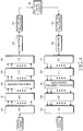
- FIG. 1 illustrates an Orthogonal Frequency Division Multiplexing (OFDM) transceiver chain.
- OFDM Orthogonal Frequency Division Multiplexing
- control signals or data 111 is modulated by modulator 112 into a series of modulation symbols, that are subsequently serial-to-parallel converted by Serial/Parallel (S/P) converter 113.
- IFFT Inverse Fast Fourier Transform
- CP Cyclic prefix
- ZP zero prefix
- the signal is transmitted by transmitter (Tx) front end processing unit 117, such as an antenna (not shown), or alternatively, by fixed wire or cable.
- transmitter (Tx) front end processing unit 117 such as an antenna (not shown), or alternatively, by fixed wire or cable.
- Tx transmitter
- Rx receiver
- FFT Fast Fourier Transform
- each OFDM symbol consists of multiple sub-carriers.
- Each sub-carrier within an OFDM symbol carriers a modulation symbol.
- FIG. 2 illustrates the OFDM transmission scheme using sub-carrier 1, sub-carrier 2, and sub-carrier 3. Because each OFDM symbol has finite duration in time domain, the sub-carriers overlap with each other in frequency domain. The orthogonality is maintained at the sampling frequency assuming the transmitter and the receiver has perfect frequency synchronization, as shown in FIG. 2 . In the case of frequency offset due to imperfect frequency synchronization or high mobility, the orthogonality of the sub-carriers at sampling frequencies is destroyed, resulting in inter-carrier-interference (ICI).
- ICI inter-carrier-interference
- FIG. 3 A time domain illustration of the transmitted and received OFDM symbols is shown in FIG. 3 .
- the CP portion of the received signal is often corrupted by the previous OFDM symbol.
- the received OFDM symbol without CP should only contain its own signal convoluted by the multipath fading channel.
- a Fast Fourier Transform FFT
- the advantage of OFDM over other transmission schemes is its robustness to multipath fading.
- the multipath fading in time domain translates into frequency selective fading in frequency domain. With the cyclic prefix or zero prefix added, the inter-symbol-interference between adjacent OFDM symbols are avoided or largely alleviated.
- each modulation symbol is carried over a narrow bandwith, it experiences a single path fading. Simple equalization scheme can be used to combat frequency selection fading.
- SC-FDMA Single carrier frequency division multiple access
- SC-FDMA Single carrier frequency division multiple access
- One advantage of SC-FDMA is that the SC-FDMA signal has lower peak-to-average power ratio (PAPR) because of its inherent single carrier structure. Low PAPR normally results in high efficiency of power amplifier, which is particularly important for mobile stations in uplink transmission.
- SC-FDMA is selected as the uplink multiple acess scheme in 3GPP long term evolution (LTE).
- LTE 3GPP long term evolution
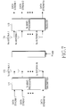
- FIG. 4 An example of the transceiver chain for SC-FDMA is shown in FIG. 4 .
- the data or control signal is serial to parallel (S/P) converted by a S/P convertor 181.
- Discrete Fourier transform will be applied to time-domain data or control signal by a DFT transmformer 182 before the time-domain data is mapped to a set of sub-carriers by a sub-carrier mapping unit 183.
- DFT Discrete Fourier transform
- the DFT output in the frequency domain will be mapped to a set of contiguous sub-carriers.
- IFFT normally with larger size than the DFT, will be applied by an IFFT transformer 184 to tranform the signal back to time domain.
- cyclic prefix (CP) will be added by a CP insertion unit 186 to the data or the control signal before the data or the control signal is transmitted to a transmission front end processing unit 187.
- the processed signal with a cyclic prefix added is often referred to as a SC-FDMA block.
- the receiver After the signal passes through a communication channel 188, e.g., a multipath fading channel in a wireless communication system, the receiver will perform receiver front end processing by a receiver front end processing unit 191, remove the CP by a CP removal unit 192, apply FFT by a FFT transformer 194 and frequency domain equalization.
- Inverse Discrete Fourier transform (IDFT) 196 will be applied after the equalized signal is demapped 195 in frequency domain. The output of IDFT will be passed for further time-domain processing such as demodulation and decoding.
- IDFT Inverse Discrete Fourier transform
- control signals transmitted through control channels i.e., control channel transmission
- data channels i.e., data transmission
- Control channel information including control channel format indicator (CCFI), acknowledgement signal (ACK), packet data control channel (PDCCH) signal
- CCFI control channel format indicator
- ACK acknowledgement signal
- PDCCH packet data control channel
- HARQ Hybrid Automatic Repeat-reQuest
- Hybrid Automatic Repeat reQuestion is widely used in communication systems to combat decoding failure and improve reliability.
- Each data packet is coded using certain forward error correction (FEC) scheme.
- FEC forward error correction
- Each subpacket may only contains a portion of the coded bits. If the transmission for subpacket k fails, as indicated by a NAK in a feedback acknowledgement channel, a retransmission subpacket, subpacket k+1, is transmitted to help the receiver decode the packet.
- the retransmission subpackets may contain different coded bits than the previous subpackets.
- the receiver may softly combine or jointly decode all the received subpackets to improve the chance of decoding. Normally, a maximum number of transmissions is configured in consideration of both reliability, packet delay, and implementation complexity.
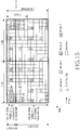
- FIG. 5 shows an example of a 4-channel synchronous HARQ. Due to fixed timing relationship between subsequent transmissions, the transmission slots in the same HARQ channel exhibits an interlace structure.
- interlace 0 consists of slot 0, 4, 8, ..., 4k, ...;
- interlace 1 consists of slot 1, 5, 9, ..., 4k+1, ...;
- interlace 2 consists of slot 2, 6, 10, ..., 4k+2, ...;
- interlace 3 consists of slot 3, 7, 11, ... 4k+3, .... Let's take interlace 0 as an example.
- a sub-packet is transmitted in slot 0.
- the receiver After correctly decoding the packet, the receiver sends back an ACK to the transmitter.
- the transmitter then can start a new packet at the next slot in this interlace, i.e., slot 4. However, the first subpacket transmitted in slot 4 is not correctly received.
- the transmitter After the transmitter receives the NAK from the receiver, the transmitter transmits another sub-packet of the same packet at the next slot in this interlace, i.e., slot 8.
- a receiver might have difficulty in detecting the packet boundary, i.e., whether a subpacket is the first sub-packet of a new packet or a retransmission sub-packet.
- a new packet indicator may be transmitted in the control channel that carries transmission format information for the packet.
- HARQ channel information such as sub-packet ID, or even HARQ channel ID, can be transmitted to help the receiver detect and decode the packet.
- MIMO multiple input multiple output
- the transmitter has multiple antennas capable of transmitting independent signals and the receiver is equipped with multiple receive antennas.
- MIMO systems degenerates to single input multiple output (SIMO) if there is only one transmission antenna or if there is only one stream of data transmitted.
- MIMO systems degenerates to multiple input signle output (MISO) if there is only one receive antenna.
- MISO multiple input signle output
- MIMO systems degenerates to single input single output (SISO) if there is only one transmission antenna and one receive antenna.
- MIMO technology can significant increase throughput and range of the system without any increase in bandwidth or overall transmit power.
- MIMO technology increases the spectral efficiency of a wireless communication system by exploiting the additional dimension of freedom in the space domain due to multiple antennas.
- MIMO technologies For example, spatial multiplexing schemes increase the transmission rate by allowing multiple data streaming transmitted over multiple antennas. Transmit diversity methods such as space-time coding take advantage of spatial diversity due to multiple transmit antennas. Receiver diversity methods utilizes the spatial diversity due to multiple receive antennas. Beamforming technologies improve received signal gain and reducing interference to other users. Spatial division multiple access (SDMA) allows signal streams from or to multiple users to be transmitted over the same time-frequency resources. The receivers can separate the multiple data streams by the spatial signature of these data streams. Note these MIMO transmission techniques are not mutually exclusive. In fact, many MIMO schemes are often used in an advanced wireless systems.
- the receivers feedback the channel condition and/or preferred Tx MIMO processing schemes.
- the transmitter utlizes this feedback information, together with other considerations such as scheduling priority, data and resource availability, to jointly optimize the transmission scheme.
- a popular closed loop MIMO scheme is called MIMO precoding. With precoding, the transmit data streams are pre-multiplied by a matrix before being passed on to the multiple transmit antennas. As shown in FIG. 6 , assume there are Nt transmit antennas and Nr receive antennas. Denote the channel between the Nt transmit antennas and the Nr receive antennas as H.
- H is an Nt x Nr matrix. If the transmitter has knowledge about H, the transmitter can choose the most advantageous transmission scheme according to H. For example, if maximizing throught is the goal, the precoding matrix can be chosen to be the right singluar matrix of H, if the knowledge of H is available at the transmitter. By doing so, the effective channel for the multiple data streams at the receiver side can be diagonalized, eliminating the interference between the multiple data streams. However, the overhead required to feedback the exact value of H is often prohibitive. In order to reduce feedback overhead, a set of precoding matrices are defined to quantize the space of the possible values that H could substantiate.
- a receiver feeds back the preferred precoding scheme, normally in the form of the index of the preferred precoding matrix, the rank, and the indices of the preferred precoding vectors.
- the receiver may also feed back the associated CQI values for the preferred precoding scheme.
- Another perspective of a MIMO system is whether the multiple data streams for transmission are encoded separately or encoded together. If all the layers for transmission are encoded together, we call it a single codeword (SCW) MIMO system. And we call it a multiple codeword (MCW) MIMO system otherwise.
- SCW single codeword
- MCW multiple codeword
- SU-MIMO single user MIMO
- up to 2 codewords can be transmitted to a single UE.
- the UE needs to acknowledge the two codewords separately.
- SDMA spatial division multiple access
- MU-MIMO multi-user MIMO
- multiple data streams are encoded separately and transmitted to different intended receivers on the same time-frequency resources.
- different spatial signature e.g., antennas, virtual antennas, or precoding vectors
- the receivers will be able to distinguish the multiple data streams.
- the signal of interest can be enhanced while the other signals can be enhanced for multiple receivers at the same time. Therefore the system capacity can be improved.
- SU-MIMO single user MIMO
- MU-MIMO multi-user MIMO
- Control channel candidate set can be constructed based on the control channel elements reserved for downlink control channels.
- Each downlink control channel can be transmitted on one of the control channel candidate set.
- An example of control channel elements and control channel candidate set is shown in FIG. 9 .
- 11 control channel candidate sets can be constructed on 6 control channel elements. In the rest of the document, we will refer to these control channel candidate sets as control channel resource sets, or simply, resource sets.
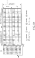
- the downlink sub frame structure in a 3GPP LTE system is shown in FIG. 10 .
- a time and frequency resource can be divided into a plurality of resource blocks 210 (RB).
- Each resource block 210 can be further divided into a plurality of resource elements 211 in a time and frequency domain.
- a single OFDM symbol can be transmitted using a row of resource elements corresponding to the same period of time.
- each subframe is 1ms long, containing 14 OFDM symbols. Assume the OFDM symbols in a subframe are indexed from 0 to 13.
- Reference symbols (RS) for antenna 0 and 1 are located in OFDM symbol 0, 4, 7, and 11.
- control channel signals including Control Channel Format Indicator (CCFI), acknowledgement signal (ACK), packet data control channel (PDCCH) signal, are transmitted in the first one, or two, or three OFDM symbols. The number of OFDM symbols used for control channel signals is indicated by CCFI.
- Data channel signals i.e., Physical Downlink Shared Channel (PDSCH) signals, are transmitted in other OFDM symbols.
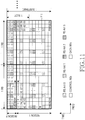
- FIG. 11 illustrates a scheme for mapping modulation symbols into a plurality of resource elements in an LTE downlink subframe according to a first embodiment of the principles of the present invention.
- 14 OFDM symbols in the LTE downlink subframe are indexed from 0 to 13.
- the control channel signals may occupy the first one, or two, or three OFDM symbols while the data channels may occupy the OFDM symbols that are not occupied by control channels.
- the LTE downlink subframe can be divided into Region 1 consisting of the resource elements corresponding to OFDM symbols 3 through 13, and Region 2 consisting of the resource elements corresponding to OFDM symbol 0, 1, and 2. Note here for ease of illustration, we assume control channels and data channels are not transmitted in the same OFDM symbol.
- Region 1 can be defined as the collection of resource elements in a subframe that are used by data channel transmission regardless of the value of certain control channel information carried in the said subframe, e.g., Control Channel Format Indicator (CCFI).
- Region 2 can be defined as the collection of resource elements in a subframe that may be used by data channel transmission if the said resource elements are not used by other overhead channels, which is indicated by certain control channel information carried in the said subframe, e.g., CCFI.
- OFDMMA Orthogonal Frequency Division Multiple Access
- the availability of the resource elements for data transmission in Region 1 consisting of OFDM symbols 3 through 13 is independent of any control channel information.
- the availability of the resource elements for data transmission in Region 2 may be, however, dependent upon some control channel information.
- the availability of the resource elements for data transmission in OFDM symbols 0, 1, and 2 in Region 2 depends on the value of CCFI. For example, if CCFI indicates OFDM symbol 0 and 1 in Region 2 are used for control channel signal transmission, then only resource elements in OFDM symbol 2 are available for data transmission.
- FIG. 12 illustrates the scheme for interleaving modulation symbols in a first stage and mapping the interleaved modulation symbols into a plurality of resource elements in a second stage according to the first embodiment of the principles of the present invention.
- the description in this invention can be viewed as the second stage operation in FIG. 12 that illustrates the mapping from modulation symbols to resources assuming a natural order or numbering of the modulation symbols. It is certainly straightforward for a person with ordinary skill in the art, however, to apply the techniques in this invention to cases where the modulation symbols are not in the natural order. As shown in FIG.
- the techniques described in this invention can be applied to the case of modulation symbols with a different order. Also note that in some other cases, the techniques described in this invention can be combined with other processing. For example, one might describe the mapping from modulation symbols to resource elements jointly for the first stage and the second stage operations as shown in FIG. 12 without departing from the disclosure of the invention.
- the method of mapping of a plurality of modulation symbols to a plurality of resource elements contemplates segregating the plurality of resource elements in a subframe into a plurality of resource regions.
- the mapping in at least one resource region in the said subframe is independent of certain control channel information carried in the said subframe, while the mapping of modulation symbols to resource elements in at least another resource region in the said subframe is dependent on the said control channel information carried in the said subframe.
- FIG. 11 shows an example of the first embodiment. As shown in FIG. 11 , two resource blocks (RBs) are allocated to a data transmission. Note these two RBs does not need to be contiguous in frequency domain.
- the other REs can be used for both control channel and data channel transmission.
- control channel signals can only be transmitted in the first three OFDM symbols.
- allocation and size of the resources for control channel transmission is indicated by the control channel format indication (CCFI) that is carried by the control channel signals.
- the resource elements (REs) in these two RBs are divided into two regions. Region 1 consists of REs corresponding to the last eleven OFDM symbols (i.e., OFDM symbols 3 through 11) in a subframe. Region 2 consists of REs corresponding to the first three OFDM symbols in a subframe.
- control and data are multiplexed in Region 2 and the allocation and size of the resources for control channel in Region 2 is indicated by CCFI.
- the allocation and size of the resources for data channel transmission in Region 2 depend on CCFI.
- coded bits generated by information bits and channel coding scheme are rate matched, interleaved, and modulated for each transmission.
- the modulation symbols may be further channel-interleaved.
- the modulation symbols are mapped to the data REs (i.e., resource elements that are available fore data channel transmission) in Region 1 in a fashion that is independent of CCFI. For example, as shown in FIG. 11 , modulation symbols are mapped to available data REs in a row-wise manner.
- modulation symbols 0-23 are mapped to the 24 data REs in the 4-th OFDM symbol (i.e., OFDM symbol 3).
- Modulation symbols 24-39 are mapped to the 16 data REs in the 5-th OFDM symbol (i.e., OFDM symbol 4).
- Modulation symbols 208 - 231 are mapped to the 24 data REs in the 14-th OFDM symbol (i.e., OFDM symbol 13).
- PDCCH control channel
- modulation symbol 232 - 255 are mapped to the 24 available data REs in the third OFDM symbol(i.e., OFDM symbol 2).
- these processing should be limited to be within Region 2 to maintain the resource allocation and modulation symbol mapping in Region 1 to be independent of CCFI.
- the mapping from modulation symbols 0 - 231 to Region 1 in FIG. 11 can be any mapping, as long the mapping does not depend on CCFI. For example, we can map modulation symbols to REs in Region 1, starting from the last OFDM symbol.
- modulation symbols 0-23 are mapped to the last OFDM symbol (i.e., OFDM symbol 13); modulation symbol 24 - 47 are mapped to the second to last OFDM symbol (i.e., OFDM symbol 12); and modulation symbols 208 - 231 are mapped to the fourth OFDM symbol (i.e., OFDM symbol 11).
- FIG. 13 illustrates a process for mapping modulation symbols according to the first embodiment of the principles of the present invention.
- the data signals and the control signals to be transmitted are modulated into a plurality of modulation symbols including data symbols and control symbols.
- the available resource elements for transmission in a subframe are divided to Region 1 and Region 2.
- the modulation symbols are mapped into Region 1 and Region 2. Specifically, the mapping of modulation symbols into Region 1 is independent of the CCFI information carried in the control signals, and the mapping of modulation symbols into Region 2 is dependent upon the CCFI information carried in the control signals.
- the modulation symbols mapped into the resource elements are transmitted via a plurality of antennas.
- FIG. 14 an operation of a receiver of the multiple-region resource mapping is illustrated in FIG. 14 .
- the receiver first decodes the CCFI information that is carried by the control channel signals. Based on the detected CCFI, the receiver can figure out which resource elements are allocated for data channel transmission in Region 2.
- the receiver collects the received modulation symbols on available data REs in Region 2 according to the mapping from modulation symbols to data REs in Region 2.
- the mapping scheme may be pre-defined before the transmission process is started. Alternatively, the transmitter may transmit a control channel signal containing the information regarding the mapping scheme.
- the receiver also collects the modulation symbols on available data REs in Region 1 to produce a first data packet according to the mapping scheme from modulation symbols to data REs in Region 1. The receiver will then attempt to decode the first data packet consisting of the modulation symbols from Region 1 only at step S440.
- the receiver checks whether the first data packet decodes by using cyclic redundancy check (CRC) function. If the first data packet decodes, i.e., cyclic redundancy check (CRC) checks, then the receiver can pass the decoded packet to upper layer for further processing at step S460. Otherwise, at step S470, the receiver produces a second data packet consisting of the modulation symbols in both Region 1 and Region 2 and attempt to decode the second data packet.
- CRC cyclic redundancy check
- the receiver passes the decoded packet to upper layer for further processing at step S460.
- the receiver can first attempt to decode the data packet with modulation symbols in both Region 1 and Region 2. If the decoding is successful, i.e., CRC checks, then the receiver can pass the decoded packet to upper layer for further processing. Otherwise, the receiver will attempt to decode the data packet with the modulation symbols in Region 1 only.
- erasure detection or CRC can be applied to the detection of the CCFI. In the case that the receiver does not successfully detect the CCFI, i.e., if CCFI erasure or CCFI detection error occurs, the receiver only uses modulation symbols in Region 1 to decode the packet. Otherwise, the receiver uses modulation symbols in both Region 1 and Region 2 to decode the packet.
- the modulation symbols 0, 1, ..., N 1 -1 are mapped to Region 1 and modulation symbols N 1 , N 1 +1, ..., N-1 are mapped to Region 2.
- modulation symbols N 1 , N 1 +1, ..., N-1 are mapped to Region 2.
- the first 232 modulation symbols are mapped to REs in Region 1 and the other 24 modulation symbols are mapped to REs in Region 2.
- the number of modulation symbols that can be transmitted equals to the number of REs available for data transmission.
- the first N 1 modulation symbols are mapped to the N 1 REs in Region 1.
- the number of available data REs and the number of modulation symbols transmitted in Region 2 depend on the value of CCFI.
- the method of mapping of modulation symbols to resource elements in a subframe contemplates segregating the resource elements in the subframe into a plurality of resource regions with the mapping of the modulation symbols in at least one resource region in the subframe utilizing the OFDM symbols in an increasing order while the mapping of the modulation symbols to resource elements in at least another resource region in the said subframe utilizing the OFDM symbols in a decreasing order.
- the mapping of modulation symbols in Region 1 starts from REs in OFDM symbol 3 while the OFDM symbols are filled in an increasing order while the mapping of modulation symbols in Region 2 starts from REs in OFDM symbol 2 while the OFDM symbols are filled in a decreasing order.
- the order that the OFDM symbols are filled with modulation symbols are 3, 4, 5, 6, 7, 8, 9, 10, 11, 12, 13, 2, 1, 0.
- CCFI control channel format indicator
- This mapping method is especially useful when there are multiple code blocks in the data transmission.
- the receiver can start decoding of some code block before receiving the whole subframe.
- FIG. 15 shows modulation symbol 0 to 23 are mapped to REs in OFDM symbol 3 in sequential order along the frequency axis.
- the order of mapping in frequency domain can be changed, e.g., by frequency domain interleaving, without departing from the scope of this invention.
- the mapping of modulation symbols of each code block to resource elements in at least one resource region is independent of certain control channel information carried in the said subframe.
- FIG. 16 An example is illustrated in FIG. 16 .
- modulation symbols that carry coded bits for code block A are transmitted on OFDM symbol 3 and 4 in Region 1, and OFDM symbol 2 in Region 2.
- Modulation symbols that carry coded bits for code block B are transmitted on OFDM symbol 4 and 5 in Region 1, and OFDM symbol 2 in Region 2.
- Modulation symbols that carry coded bits for code block C are transmitted on OFDM symbol 5 and 6 in Region 1, and OFDM symbol 2 in Region 2.
- mapping of modulation symbols within each code block into resource elements within at least one resource region being independent of certain control channel information carried in the said subframe while the mapping of modulation symbols of each code block into resource elements within at least another resource region being dependent of certain control channel information carried in the said subframe.
- the number and location of data REs for code block A, B, and C in Region 2 depend on the CCFI information, while the number and location of data REs for code block A, B, and C in Region 1 does not depend on the CCFI information.
- the number of data REs in at least one resource region among a plurality of resource regions is allocated roughly equally among the multiple code blocks to ensure about equal error protection on each code block. Since there is only one CRC for the whole transport block, it is important for each code block to receive as much error protection as possible. Note that the number of available data REs may not be divisible by the number of code blocks. So, we can only ensure roughly equal number of data REs assigned to each code block. Assuming there are N 1 modulation symbols available for data transmission in Region 1 and N 2 modulation symbols available for data transmission in Region 2. Assume there are N seg code blocks. Define ⁇ x ⁇ as the smallest integer that is larger than or equal to x.
- ⁇ x ⁇ as the largest integer that is smaller than or equal to x.
- x mod y is the remainder of x y .
- M j ,1 ⁇ ⁇ N 1 N seg ⁇ , 0 ⁇ j ⁇ N 1 mod N seg ⁇ N 1 N seg ⁇ , N 1 mod N seg ⁇ j ⁇ N seg .
- M j , 2 ⁇ ⁇ N 2 N seg ⁇ , 0 ⁇ j ⁇ N 2 mod N seg ⁇ N 2 N seg ⁇ , N 2 mod N seg ⁇ j ⁇ N seg .
- this embodiment is still applicable when there is only one resource region, i.e., all data REs belong to the same resource region.
- the number of data resource elements is almost equally allocated among the multiple code blocks.
- the number of data resource elements of code block j can be given by Equation (1).
- the number of data resource elements of code block j can be given by Equation (3). Note that for the case of only one resource region, N 1 is the total number of resource elements.
- the number of coded bits, or the number of modulation positions in modulation symbols, in at least one resource region is allocated roughly equally among the multiple code blocks to ensure about equal error protection on each code block.
- a modulation position is one of the L bits that an L -th order modulation symbol carries.
- a total number of N 1 ⁇ L coded bits can be transmitted in Region 1.
- a total number of N 2 ⁇ L coded bits can be transmitted in Region 2.
- the resource assignment can be done on a coded-bit basis.
- this embodiment is still applicable when there is only one resource region, i.e., all data REs belong to the same resource region.
- the number of coded bit is almost equally allocated among the multiple code blocks.
- the number of coded bits assigned to code block j can be given by Equation (5).
- the number of coded bits assigned to code block j can be given by Equation (7). Note that for the case of only one resource region, N 1 is the total number of resource elements.
- the number of data REs in at least one resource region is allocated to achieve roughly equal coding rate among the multiple code blocks to ensure about equal error protection on each code block.
- this embodiment is still applicable when there is only one resource region, i.e., all data REs belong to the same resource region.
- the number of data REs is allocated to achieve roughly equal coding rate.
- the number of data REs assigned to code block j can be given by Equation (9).
- the number of data REs assigned to code block j can be given by Equation (13). Note that for the case of only one resource region, N 1 is the total number of resource elements.
- the number of coded bits, or the number of modulation positions in modulation symbols, in at least one resource region is allocated to achieve roughly equal coding rate among the multiple code blocks to ensure about equal error protection on each code block.
- this embodiment is still applicable when there is only one resource region, i.e., all data REs belong to the same resource region.
- the number of coded bits is allocated to achieve roughly equal coding rate among the multiple code blocks.
- the number of coded bits assigned to code block j can be given by Equation (15).
- the number of data REs assigned to code block j can be given by Equation (19). Note that for the case of only one resource region, N 1 is the total number of resource elements.
Landscapes
- Engineering & Computer Science (AREA)
- Signal Processing (AREA)
- Computer Networks & Wireless Communication (AREA)
- Mobile Radio Communication Systems (AREA)
Claims (6)
- Verfahren zum Übertragen von Informationsbits unter Verwendung einer Vielzahl von Ressourcen durch eine Sendevorrichtung in einem drahtlosen Kommunikationssystem, wobei das Verfahren die folgenden Schritte umfasst:Segmentieren der zu übertragenden Informationsbits in mehrere Codeblöcke, wobei mindestens ein Codeblock am Anfang der mehreren Codeblöcke eine geringere Anzahl von Informationsbits enthält;Codieren der Informationsbits in jedem Codeblock;Modulieren (S310) der Vielzahl von codierten Bits in den Codeblöcken, um eine Sequenz von Modulationssymbolen zu erzeugen;Zuweisen (S320) einer Anzahl von Ressourcen zu jedem der mehreren Codeblöcke, wobei eine Anzahl von Ressourcen, die zu Beginn der mehreren Codeblöcke mindestens einem Codeblock zugewiesen sind, geringer ist, als eine Anzahl von Ressourcen, die mindestens einem Codeblock am Ende der mehreren Codeblöcke zugewiesen ist, wenn N1 nicht ohne Rest durch Nseg geteilt werden kann, wobei N1 die Anzahl der für die Datenübertragung verfügbaren Ressourcen und Nseg die Anzahl der Codeblöcke ist; undSenden (S340) der Modulationssymbole an einen Empfänger über eine oder mehrere Antennen basierend auf den zugewiesenen Ressourcen,wobei die Anzahl der Ressourcen, die einem Codeblock (j) zugewiesen sind, durch:

wobei ┌x┐ die kleinste ganze Zahl ist, die größer oder gleich x ist, └x┘ die größte ganze Zahl ist, die kleiner oder gleich x ist, und x mod y den Rest von
- Verfahren nach Anspruch 1, wobei die Informationsbits durch einen Unterrahmen übertragen werden, der einen Ressourcenbereich für die Informationsbits und einen anderen Ressourcenbereich für Steuerbits enthält, wobei der Ressourcenbereich für die Informationsbits und der andere Ressourcenbereich für die Steuerbits mindestens ein Multiplexsymbol umfassen, wobei jedes Multiplexsymbol in einer Zeitdomäne mehrere Ressourcen in einer Frequenzdomäne umfasst.
- Verfahren nach Anspruch 2, wobei die Steuerungsbits eine Steuerkanalformatanzeige umfassen und die Steuerkanalformatanzeige die Anzahl von Multiplexsymbolen anzeigt, die für die Steuerungsbits verwendet werden.
- Verfahren nach Anspruch 1, ferner die folgenden Schritte umfassend:Verschachteln der codierten Informationsbits;Modulieren der verschachtelten Informationsbits, um Modulationssymbole zu erzeugen; undZuordnen der Modulationssymbole zu den zugewiesenen Ressourcen.
- Verfahren nach Anspruch 2, wobei die Informationsbits dem Ressourcenbereich in aufsteigender Reihenfolge zugeordnet werden, beginnend mit einem Multiplexsymbol mit dem kleinsten Index in der Zeitdomäne.
- Sendevorrichtung mit einem Sender (110), der zum Betrieb nach einem der Ansprüche 1 bis 5 eingerichtet ist.
Applications Claiming Priority (3)
| Application Number | Priority Date | Filing Date | Title |
|---|---|---|---|
| US92486107P | 2007-06-01 | 2007-06-01 | |
| US12/076,938 US7885176B2 (en) | 2007-06-01 | 2008-03-25 | Methods and apparatus for mapping modulation symbols to resources in OFDM systems |
| PCT/KR2008/003018 WO2008147122A1 (en) | 2007-06-01 | 2008-05-29 | Methods and apparatus for mapping modulation symbols to resources in ofdm systems |
Publications (3)
| Publication Number | Publication Date |
|---|---|
| EP2163017A1 EP2163017A1 (de) | 2010-03-17 |
| EP2163017A4 EP2163017A4 (de) | 2016-10-05 |
| EP2163017B1 true EP2163017B1 (de) | 2019-07-17 |
Family
ID=40075275
Family Applications (1)
| Application Number | Title | Priority Date | Filing Date |
|---|---|---|---|
| EP08765980.1A Active EP2163017B1 (de) | 2007-06-01 | 2008-05-29 | Verfahren und vorrichtung zur abbildung von modulationssymbolen auf ressourcen in ofdm-systemen |
Country Status (10)
| Country | Link |
|---|---|
| US (4) | US7885176B2 (de) |
| EP (1) | EP2163017B1 (de) |
| JP (2) | JP5231539B2 (de) |
| KR (1) | KR101457242B1 (de) |
| CN (2) | CN101682451B (de) |
| AU (1) | AU2008257985B2 (de) |
| CA (1) | CA2687803C (de) |
| DE (1) | DE202008018250U1 (de) |
| RU (1) | RU2441325C2 (de) |
| WO (1) | WO2008147122A1 (de) |
Families Citing this family (67)
| Publication number | Priority date | Publication date | Assignee | Title |
|---|---|---|---|---|
| EP2015486B1 (de) * | 2006-04-28 | 2017-04-12 | TCL Communication Technology Holdings Limited | Drahtlose kommunikationsvorrichtung |
| EP2080302A4 (de) | 2006-10-02 | 2014-04-02 | Lg Electronics Inc | Verfahren zum senden eines steuersignals unter verwendung eines effizienten multiplexverfahrens |
| US8305957B2 (en) * | 2007-01-09 | 2012-11-06 | Nokia Corporation | Apparatus, method and computer program product providing per-UE signaling technique for separately coded users |
| KR101049138B1 (ko) | 2007-03-19 | 2011-07-15 | 엘지전자 주식회사 | 이동 통신 시스템에서, 수신확인신호 수신 방법 |
| EP3487113B1 (de) | 2007-03-19 | 2021-10-06 | LG Electronics Inc. | Ressourcenzuweisungsverfahren und verfahren für sendung/empfang von ressourcenzuweisungsinformationen in einem mobilkommunikationssystem |
| EP2127135B1 (de) * | 2007-03-26 | 2015-01-21 | Telefonaktiebolaget L M Ericsson (publ) | Verfahren und anordnung in bezug auf ein kommunikationsnetzwerk |
| US7885176B2 (en) * | 2007-06-01 | 2011-02-08 | Samsung Electronics Co., Ltd. | Methods and apparatus for mapping modulation symbols to resources in OFDM systems |
| KR100913090B1 (ko) | 2007-06-13 | 2009-08-21 | 엘지전자 주식회사 | 통신 시스템에서 확산 신호를 송신하는 방법 |
| KR100900289B1 (ko) * | 2007-06-21 | 2009-05-29 | 엘지전자 주식회사 | 직교 주파수 분할 다중화 시스템에서 제어 채널을 송수신하는 방법 |
| CN104270230B (zh) * | 2007-06-22 | 2018-01-02 | Tcl通讯科技控股有限公司 | 通信方法及移动终端 |
| US8576807B2 (en) * | 2007-06-25 | 2013-11-05 | Qualcomm Incorporated | Channel interleaving structure for a wireless communication system |
| BRPI0721890A2 (pt) * | 2007-08-02 | 2011-05-03 | Fujitsu Ltd | método de arranjo piloto em sistema de comunicação de rádio móvel e transmissor/receptor adotando o mesmo |
| US20110096862A1 (en) * | 2007-08-09 | 2011-04-28 | Panasonic Corporation | Radio communication apparatus, radio communication system, and radio communication method |
| KR101531416B1 (ko) | 2007-09-13 | 2015-06-24 | 옵티스 셀룰러 테크놀로지, 엘엘씨 | 상향링크 신호 전송 방법 |
| KR101376233B1 (ko) * | 2007-10-02 | 2014-03-21 | 삼성전자주식회사 | 주파수 분할 다중 접속 방식의 시스템에서 제어 채널의자원 할당 장치 및 방법 |
| CA2703252C (en) * | 2007-10-29 | 2016-06-07 | Telefonaktiebolaget Lm Ericsson (Publ) | Control channel data allocation method in ofdm systems |
| US9287951B2 (en) * | 2007-12-03 | 2016-03-15 | Telefonaktiebolaget L M Ericsson (Publ) | Precoder for spatial multiplexing, multiple antenna transmitter |
| EP2073419B1 (de) | 2007-12-20 | 2011-10-26 | Panasonic Corporation | Steuerkanalsignalisierung über ein herkömmliches Signalisierungsfeld für Transportformat und Redundanzversion |
| KR100943908B1 (ko) | 2008-02-19 | 2010-02-24 | 엘지전자 주식회사 | Pdcch를 통한 제어 정보 송수신 방법 |
| WO2009107985A1 (en) | 2008-02-28 | 2009-09-03 | Lg Electronics Inc. | Method for multiplexing data and control information |
| EP2248294B1 (de) | 2008-03-16 | 2018-05-02 | LG Electronics Inc. | Verfahren zur durchführung von hybriden automatischen wiederholungsanforderung in einem drahtlosen kommunikationssystem |
| KR100921467B1 (ko) | 2008-06-19 | 2009-10-13 | 엘지전자 주식회사 | 셀룰라 다중반송파 시스템에서 조밀도를 조절하는 자원할당시그널링 방식 |
| US8098750B2 (en) * | 2008-07-10 | 2012-01-17 | Infineon Technologies Ag | Method and device for transmitting a plurality of data symbols |
| WO2010018987A2 (ko) * | 2008-08-12 | 2010-02-18 | 엘지전자주식회사 | 다중 반송파 시스템에서 데이터 전송 방법 및 전송기 |
| KR101478028B1 (ko) * | 2008-09-23 | 2014-12-31 | 삼성전자주식회사 | 확장성 대역폭을 지원하는 셀룰러 무선통신시스템을 위한 하향링크채널의 송수신 방법 및 장치 |
| CN101686534A (zh) * | 2008-09-23 | 2010-03-31 | 华为技术有限公司 | 选择下行主载波进行数据传输的方法、终端及系统 |
| US8031670B2 (en) * | 2008-11-13 | 2011-10-04 | Telefonaktiebolaget L M Ericsson (Publ) | Systems and methods for selecting the size of a control region of a downlink subframe |
| KR101481590B1 (ko) | 2008-12-09 | 2015-01-13 | 엘지전자 주식회사 | 하향링크 mimo시스템에 있어서 rs 전송 방법 |
| US11218194B2 (en) | 2009-03-23 | 2022-01-04 | Lg Electronics Inc. | Method and apparatus for transmitting reference signal in multi-antenna system |
| US8675481B2 (en) | 2009-03-23 | 2014-03-18 | Lg Electronics Inc. | Method and apparatus for transmitting reference signal in multi-antenna system |
| US20120076043A1 (en) * | 2009-06-22 | 2012-03-29 | Panasonic Corporation | Wireless communication base station device, wireless communication terminal device, control channel transmission method, and control channel reception method |
| CN102026337B (zh) * | 2009-09-21 | 2013-09-11 | 中兴通讯股份有限公司 | 一种资源元的映射方法和装置 |
| CN102014503B (zh) * | 2009-09-29 | 2013-07-31 | 电信科学技术研究院 | 中继系统控制信道配置方法、检测方法及设备 |
| US8434336B2 (en) * | 2009-11-14 | 2013-05-07 | Qualcomm Incorporated | Method and apparatus for managing client initiated transmissions in multiple-user communication schemes |
| CN102123503B (zh) * | 2010-01-07 | 2016-02-10 | 中兴通讯股份有限公司 | 一种中继链路的物理下行共享信道的资源分配方法及装置 |
| CA2792763C (en) | 2010-04-23 | 2016-08-16 | Lg Electronics Inc. | Method for transceiving signals between a base station and a relay node in a multiuser multi-antenna wireless communication system, and apparatus for same |
| US8848649B2 (en) * | 2010-07-12 | 2014-09-30 | Lg Electronics Inc. | Method for transmitting an uplink signal, and apparatus for same |
| US8824267B2 (en) * | 2010-08-13 | 2014-09-02 | Telefonaktiebolaget L M Ericsson (Publ) | Systems and methods for transmit diversity for DFT precoded channels |
| EP2421187B1 (de) | 2010-08-20 | 2018-02-28 | LG Electronics Inc. | Verfahren zur Übertragung von Steuerinformationen in einem drahtlosen Kommunikationssystem und Vorrichtung dafür |
| US9119196B2 (en) | 2010-09-07 | 2015-08-25 | Panasonic Intellectual Property Corporation Of America | Base station, terminal, transmission method, and reception method |
| US9380490B2 (en) | 2010-11-08 | 2016-06-28 | Qualcomm Incorporated | System and method for uplink multiple input multiple output transmission |
| US9007888B2 (en) | 2010-11-08 | 2015-04-14 | Qualcomm Incorporated | System and method for uplink multiple input multiple output transmission |
| US8953713B2 (en) * | 2010-11-08 | 2015-02-10 | Qualcomm Incorporated | System and method for uplink multiple input multiple output transmission |
| US9084207B2 (en) | 2010-11-08 | 2015-07-14 | Qualcomm Incorporated | System and method for uplink multiple input multiple output transmission |
| US9516609B2 (en) | 2010-11-08 | 2016-12-06 | Qualcomm Incorporated | System and method for uplink multiple input multiple output transmission |
| US8842542B2 (en) | 2012-02-08 | 2014-09-23 | Qualcomm Incorporated | Method and apparatus for scheduling resources for uplink MIMO communication |
| CN102468917B (zh) * | 2010-11-15 | 2014-04-30 | 华为技术有限公司 | 上行控制信息的传输和接收方法、终端以及基站 |
| US9136994B2 (en) | 2011-05-11 | 2015-09-15 | Lg Electronics Inc. | Method and device for transmitting data in a multi antenna wireless communication system |
| KR101943821B1 (ko) * | 2011-06-21 | 2019-01-31 | 한국전자통신연구원 | 무선 통신 시스템에서 제어채널 송수신 방법 |
| US9602255B2 (en) * | 2011-10-13 | 2017-03-21 | Futurewei Technologies, Inc. | System and method for data channel transmission and reception |
| US11239971B2 (en) * | 2011-11-03 | 2022-02-01 | Texas Instruments Incorporated | Method and apparatus with enhanced control messages and search space |
| US8930800B2 (en) * | 2012-08-14 | 2015-01-06 | GM Global Technology Operations LLC | Method and apparatus of triple-decoding for IEEE 802.11p physical layer mechanism |
| JP6294327B2 (ja) * | 2012-09-20 | 2018-03-14 | エルジー エレクトロニクス インコーポレイティド | 無線通信システムにおけるアンテナポート相互関係を考慮した下りリンク信号送受信方法及び装置 |
| US9226196B2 (en) * | 2012-11-16 | 2015-12-29 | Huawei Technologies Co., Ltd. | Systems and methods for pilot signal and control data retransmission |
| US9344123B2 (en) | 2012-11-19 | 2016-05-17 | Huawei Technologies Co., Ltd. | Systems and methods for historical signal interference cancellation (SIC) |
| US10075266B2 (en) * | 2013-10-09 | 2018-09-11 | Qualcomm Incorporated | Data transmission scheme with unequal code block sizes |
| KR102171797B1 (ko) * | 2014-02-28 | 2020-10-29 | 삼성전자주식회사 | 무선 통신 시스템에서 비가우시안 간섭채널을 생성하기 위한 방법 및 장치 |
| CN105792360B (zh) * | 2014-12-24 | 2020-02-14 | 中兴通讯股份有限公司 | 超级小区下资源分配的方法及装置 |
| CN107078765B (zh) * | 2015-01-29 | 2021-02-26 | 松下电器(美国)知识产权公司 | 无线通信方法和装置 |
| US10348466B2 (en) | 2015-11-03 | 2019-07-09 | Qualcomm Incorporated | Transport block segmentation and signaling |
| CN106685620B (zh) * | 2015-11-06 | 2021-02-12 | 中兴通讯股份有限公司 | 信道状态测量导频的配置方法及装置、解析方法及装置 |
| EP3633896B1 (de) * | 2017-03-08 | 2022-10-05 | LG Electronics Inc. | Verfahren und vorrichtung zum senden und empfangen von funksignalen in einem drahtlosen kommunikationssystem |
| CN108809592B (zh) * | 2017-05-05 | 2021-06-15 | 华为技术有限公司 | 数据传输方法和设备 |
| US20200204414A1 (en) * | 2018-12-19 | 2020-06-25 | Industrial Technology Research Institute | Communication device and method for transmitting and receiving using the same |
| CN111757448B (zh) * | 2019-03-29 | 2021-09-07 | 华为技术有限公司 | 一种功率控制方法及装置 |
| US11411672B2 (en) * | 2019-09-03 | 2022-08-09 | Electronics And Telecommunication Research Institute | Method and apparatus for data transmission in wireless communication system |
| US11316616B2 (en) * | 2020-02-21 | 2022-04-26 | Qualcomm Incorporated | Constraint-based code block interleaver for data aided receivers |
Family Cites Families (32)
| Publication number | Priority date | Publication date | Assignee | Title |
|---|---|---|---|---|
| US5144304A (en) * | 1989-07-17 | 1992-09-01 | Digital Equipment Corporation | Data and forward error control coding techniques for digital signals |
| KR980007105A (ko) | 1996-06-28 | 1998-03-30 | 김광호 | 이동국 송신전력 제어방법 |
| US6473467B1 (en) | 2000-03-22 | 2002-10-29 | Qualcomm Incorporated | Method and apparatus for measuring reporting channel state information in a high efficiency, high performance communications system |
| US6697988B2 (en) | 2000-05-24 | 2004-02-24 | Samsung Electronics Co., Ltd. | Data transmission apparatus and method for an HARQ data communication system |
| US6567465B2 (en) * | 2001-05-21 | 2003-05-20 | Pc Tel Inc. | DSL modem utilizing low density parity check codes |
| US7272769B1 (en) | 2001-06-05 | 2007-09-18 | Broadcom Corporation | System and method for interleaving data in a wireless transmitter |
| US6996767B2 (en) * | 2001-08-03 | 2006-02-07 | Combasis Technology, Inc. | Memory configuration scheme enabling parallel decoding of turbo codes |
| RU2207723C1 (ru) | 2001-10-01 | 2003-06-27 | Военный университет связи | Способ распределения ресурсов в системе электросвязи с множественным доступом |
| KR100762632B1 (ko) * | 2001-10-17 | 2007-10-01 | 삼성전자주식회사 | 부호 분할 다중 접속 통신 시스템에서 전송 채널 다중화/역다중화 장치 및 방법 |
| US7260139B2 (en) * | 2002-10-22 | 2007-08-21 | Intel Corporation | Method to reduce the number of bits per soft bit |
| US20040081131A1 (en) * | 2002-10-25 | 2004-04-29 | Walton Jay Rod | OFDM communication system with multiple OFDM symbol sizes |
| US8509051B2 (en) * | 2003-09-02 | 2013-08-13 | Qualcomm Incorporated | Multiplexing and transmission of multiple data streams in a wireless multi-carrier communication system |
| US7221680B2 (en) * | 2003-09-02 | 2007-05-22 | Qualcomm Incorporated | Multiplexing and transmission of multiple data streams in a wireless multi-carrier communication system |
| KR100606101B1 (ko) * | 2004-07-01 | 2006-07-31 | 삼성전자주식회사 | 직교 주파수 분할 다중 접속 방식을 사용하는 통신시스템에서 상향링크 제어 정보 전송 시스템 및 방법 |
| KR20060006542A (ko) * | 2004-07-16 | 2006-01-19 | 삼성전자주식회사 | Ofdm기반의 무선랜 시스템을 위한 mimo 전송장치및 전송방식 |
| US20060218459A1 (en) * | 2004-08-13 | 2006-09-28 | David Hedberg | Coding systems and methods |
| CN1780457A (zh) * | 2004-11-24 | 2006-05-31 | 北京三星通信技术研究有限公司 | 无线信道资源分配方法 |
| US8826093B2 (en) * | 2005-01-19 | 2014-09-02 | Qualcomm Incorporated | Power saving method for coded transmission |
| US20060259981A1 (en) * | 2005-05-13 | 2006-11-16 | Yaron Ben-Shoshan | System and method of controlling and monitoring computer program usage |
| US20080209525A1 (en) * | 2005-05-13 | 2008-08-28 | Yaron Ben-Shoshan | Applications and uses for system and method of controlling and monitoring computer program usage |
| KR101208524B1 (ko) * | 2005-08-23 | 2012-12-05 | 엘지전자 주식회사 | 다중 반송파 시스템에서의 무선 자원 할당 방법 |
| CN1805318B (zh) * | 2005-08-24 | 2010-05-12 | 华为技术有限公司 | 一种上行时频资源的分配方法 |
| UA91880C2 (ru) | 2005-10-27 | 2010-09-10 | Квелкомм Інкорпорейтед | Предварительное кодирование для планирования в беспроводных системах связи, которое зависит от сегмента |
| KR100996023B1 (ko) * | 2005-10-31 | 2010-11-22 | 삼성전자주식회사 | 다중 안테나 통신 시스템에서 데이터 송수신 장치 및 방법 |
| US7397400B2 (en) * | 2005-12-02 | 2008-07-08 | Viasat, Inc. | Variable length data encapsulation and encoding |
| EP3471301B1 (de) * | 2006-02-24 | 2020-01-22 | Sun Patent Trust | Ressourcenblockkandidatauswahlverfahren mit verwendung von paketzeitplanung in drahtloskommunikationssystemen |
| EP2015486B1 (de) * | 2006-04-28 | 2017-04-12 | TCL Communication Technology Holdings Limited | Drahtlose kommunikationsvorrichtung |
| US9143288B2 (en) * | 2006-07-24 | 2015-09-22 | Qualcomm Incorporated | Variable control channel for a wireless communication system |
| US8320407B2 (en) * | 2007-01-05 | 2012-11-27 | Qualcomm Incorporated | Mapping of subpackets to resources in a communication system |
| WO2008133415A1 (en) * | 2007-04-27 | 2008-11-06 | Lg Electronics Inc. | A method for transmitting downlink control channel in a mobile communication system and a method for mapping the control channel to physical resource using block interleaver in a mobile communication system |
| US7885176B2 (en) * | 2007-06-01 | 2011-02-08 | Samsung Electronics Co., Ltd. | Methods and apparatus for mapping modulation symbols to resources in OFDM systems |
| KR20120030919A (ko) | 2010-09-20 | 2012-03-29 | 엘지전자 주식회사 | 무선 통신 시스템에서 캐리어 집성 방법 및 장치 |
-
2008
- 2008-03-25 US US12/076,938 patent/US7885176B2/en active Active
- 2008-05-29 WO PCT/KR2008/003018 patent/WO2008147122A1/en active Application Filing
- 2008-05-29 DE DE202008018250U patent/DE202008018250U1/de not_active Expired - Lifetime
- 2008-05-29 JP JP2010510213A patent/JP5231539B2/ja active Active
- 2008-05-29 AU AU2008257985A patent/AU2008257985B2/en active Active
- 2008-05-29 CA CA2687803A patent/CA2687803C/en active Active
- 2008-05-29 EP EP08765980.1A patent/EP2163017B1/de active Active
- 2008-05-29 RU RU2009144112/07A patent/RU2441325C2/ru active
- 2008-05-29 CN CN2008800176764A patent/CN101682451B/zh active Active
- 2008-05-29 KR KR1020097018439A patent/KR101457242B1/ko active IP Right Grant
- 2008-05-29 CN CN201210459023.XA patent/CN102932129B/zh active Active
-
2011
- 2011-01-14 US US13/007,367 patent/US8526392B2/en active Active
-
2013
- 2013-03-21 JP JP2013058088A patent/JP5614905B2/ja active Active
- 2013-09-03 US US14/017,137 patent/US9118454B2/en active Active
-
2015
- 2015-06-17 US US14/742,477 patent/US10148394B2/en active Active
Non-Patent Citations (1)
| Title |
|---|
| None * |
Also Published As
| Publication number | Publication date |
|---|---|
| US20080298224A1 (en) | 2008-12-04 |
| EP2163017A1 (de) | 2010-03-17 |
| JP2013176069A (ja) | 2013-09-05 |
| WO2008147122A1 (en) | 2008-12-04 |
| JP5614905B2 (ja) | 2014-10-29 |
| RU2009144112A (ru) | 2011-06-10 |
| JP2010529729A (ja) | 2010-08-26 |
| AU2008257985B2 (en) | 2011-08-11 |
| US10148394B2 (en) | 2018-12-04 |
| KR101457242B1 (ko) | 2014-10-31 |
| US20140071913A1 (en) | 2014-03-13 |
| US20110200003A1 (en) | 2011-08-18 |
| JP5231539B2 (ja) | 2013-07-10 |
| AU2008257985A1 (en) | 2008-12-04 |
| US20150288493A1 (en) | 2015-10-08 |
| US8526392B2 (en) | 2013-09-03 |
| CA2687803C (en) | 2015-10-27 |
| US9118454B2 (en) | 2015-08-25 |
| DE202008018250U1 (de) | 2012-04-11 |
| CN102932129A (zh) | 2013-02-13 |
| CN102932129B (zh) | 2015-09-02 |
| US7885176B2 (en) | 2011-02-08 |
| EP2163017A4 (de) | 2016-10-05 |
| RU2441325C2 (ru) | 2012-01-27 |
| KR20100014900A (ko) | 2010-02-11 |
| CA2687803A1 (en) | 2008-12-04 |
| CN101682451B (zh) | 2013-05-22 |
| CN101682451A (zh) | 2010-03-24 |
Similar Documents
| Publication | Publication Date | Title |
|---|---|---|
| EP2163017B1 (de) | Verfahren und vorrichtung zur abbildung von modulationssymbolen auf ressourcen in ofdm-systemen | |
| EP2720377B1 (de) | Verfahren und Vorrichtung zum Empfang von Daten in einem Kommunikationssystem | |
| US9131465B2 (en) | Methods and apparatus for mapping control channels to resources in OFDM systems | |
| US20080232307A1 (en) | Method and apparatus to allocate resources for acknowledgments in communication systems | |
| RU2421947C1 (ru) | Способы и устройство для канального перемежения в системах ofdm |
Legal Events
| Date | Code | Title | Description |
|---|---|---|---|
| PUAI | Public reference made under article 153(3) epc to a published international application that has entered the european phase |
Free format text: ORIGINAL CODE: 0009012 |
|
| 17P | Request for examination filed |
Effective date: 20091222 |
|
| AK | Designated contracting states |
Kind code of ref document: A1 Designated state(s): AT BE BG CH CY CZ DE DK EE ES FI FR GB GR HR HU IE IS IT LI LT LU LV MC MT NL NO PL PT RO SE SI SK TR |
|
| AX | Request for extension of the european patent |
Extension state: AL BA MK RS |
|
| DAX | Request for extension of the european patent (deleted) | ||
| RAP1 | Party data changed (applicant data changed or rights of an application transferred) |
Owner name: SAMSUNG ELECTRONICS CO., LTD. |
|
| RIC1 | Information provided on ipc code assigned before grant |
Ipc: H04L 27/26 20060101ALN20160510BHEP Ipc: H04L 5/00 20060101ALI20160510BHEP Ipc: H04J 11/00 20060101AFI20160510BHEP |
|
| RA4 | Supplementary search report drawn up and despatched (corrected) |
Effective date: 20160902 |
|
| RIC1 | Information provided on ipc code assigned before grant |
Ipc: H04L 5/00 20060101ALI20160829BHEP Ipc: H04J 11/00 20060101AFI20160829BHEP Ipc: H04L 27/26 20060101ALN20160829BHEP |
|
| STAA | Information on the status of an ep patent application or granted ep patent |
Free format text: STATUS: EXAMINATION IS IN PROGRESS |
|
| 17Q | First examination report despatched |
Effective date: 20180209 |
|
| GRAP | Despatch of communication of intention to grant a patent |
Free format text: ORIGINAL CODE: EPIDOSNIGR1 |
|
| STAA | Information on the status of an ep patent application or granted ep patent |
Free format text: STATUS: GRANT OF PATENT IS INTENDED |
|
| RIC1 | Information provided on ipc code assigned before grant |
Ipc: H04L 5/00 20060101ALI20190308BHEP Ipc: H04J 11/00 20060101AFI20190308BHEP Ipc: H04L 27/26 20060101ALN20190308BHEP |
|
| INTG | Intention to grant announced |
Effective date: 20190402 |
|
| GRAS | Grant fee paid |
Free format text: ORIGINAL CODE: EPIDOSNIGR3 |
|
| GRAA | (expected) grant |
Free format text: ORIGINAL CODE: 0009210 |
|
| STAA | Information on the status of an ep patent application or granted ep patent |
Free format text: STATUS: THE PATENT HAS BEEN GRANTED |
|
| AK | Designated contracting states |
Kind code of ref document: B1 Designated state(s): AT BE BG CH CY CZ DE DK EE ES FI FR GB GR HR HU IE IS IT LI LT LU LV MC MT NL NO PL PT RO SE SI SK TR |
|
| REG | Reference to a national code |
Ref country code: GB Ref legal event code: FG4D |
|
| REG | Reference to a national code |
Ref country code: CH Ref legal event code: EP |
|
| REG | Reference to a national code |
Ref country code: IE Ref legal event code: FG4D |
|
| REG | Reference to a national code |
Ref country code: DE Ref legal event code: R096 Ref document number: 602008060693 Country of ref document: DE |
|
| REG | Reference to a national code |
Ref country code: AT Ref legal event code: REF Ref document number: 1156786 Country of ref document: AT Kind code of ref document: T Effective date: 20190815 |
|
| REG | Reference to a national code |
Ref country code: NL Ref legal event code: FP |
|
| REG | Reference to a national code |
Ref country code: LT Ref legal event code: MG4D |
|
| REG | Reference to a national code |
Ref country code: AT Ref legal event code: MK05 Ref document number: 1156786 Country of ref document: AT Kind code of ref document: T Effective date: 20190717 |
|
| PG25 | Lapsed in a contracting state [announced via postgrant information from national office to epo] |
Ref country code: LT Free format text: LAPSE BECAUSE OF FAILURE TO SUBMIT A TRANSLATION OF THE DESCRIPTION OR TO PAY THE FEE WITHIN THE PRESCRIBED TIME-LIMIT Effective date: 20190717 Ref country code: FI Free format text: LAPSE BECAUSE OF FAILURE TO SUBMIT A TRANSLATION OF THE DESCRIPTION OR TO PAY THE FEE WITHIN THE PRESCRIBED TIME-LIMIT Effective date: 20190717 Ref country code: PT Free format text: LAPSE BECAUSE OF FAILURE TO SUBMIT A TRANSLATION OF THE DESCRIPTION OR TO PAY THE FEE WITHIN THE PRESCRIBED TIME-LIMIT Effective date: 20191118 Ref country code: SE Free format text: LAPSE BECAUSE OF FAILURE TO SUBMIT A TRANSLATION OF THE DESCRIPTION OR TO PAY THE FEE WITHIN THE PRESCRIBED TIME-LIMIT Effective date: 20190717 Ref country code: HR Free format text: LAPSE BECAUSE OF FAILURE TO SUBMIT A TRANSLATION OF THE DESCRIPTION OR TO PAY THE FEE WITHIN THE PRESCRIBED TIME-LIMIT Effective date: 20190717 Ref country code: BG Free format text: LAPSE BECAUSE OF FAILURE TO SUBMIT A TRANSLATION OF THE DESCRIPTION OR TO PAY THE FEE WITHIN THE PRESCRIBED TIME-LIMIT Effective date: 20191017 Ref country code: AT Free format text: LAPSE BECAUSE OF FAILURE TO SUBMIT A TRANSLATION OF THE DESCRIPTION OR TO PAY THE FEE WITHIN THE PRESCRIBED TIME-LIMIT Effective date: 20190717 Ref country code: NO Free format text: LAPSE BECAUSE OF FAILURE TO SUBMIT A TRANSLATION OF THE DESCRIPTION OR TO PAY THE FEE WITHIN THE PRESCRIBED TIME-LIMIT Effective date: 20191017 |
|
| PG25 | Lapsed in a contracting state [announced via postgrant information from national office to epo] |
Ref country code: IS Free format text: LAPSE BECAUSE OF FAILURE TO SUBMIT A TRANSLATION OF THE DESCRIPTION OR TO PAY THE FEE WITHIN THE PRESCRIBED TIME-LIMIT Effective date: 20191117 Ref country code: ES Free format text: LAPSE BECAUSE OF FAILURE TO SUBMIT A TRANSLATION OF THE DESCRIPTION OR TO PAY THE FEE WITHIN THE PRESCRIBED TIME-LIMIT Effective date: 20190717 Ref country code: LV Free format text: LAPSE BECAUSE OF FAILURE TO SUBMIT A TRANSLATION OF THE DESCRIPTION OR TO PAY THE FEE WITHIN THE PRESCRIBED TIME-LIMIT Effective date: 20190717 Ref country code: GR Free format text: LAPSE BECAUSE OF FAILURE TO SUBMIT A TRANSLATION OF THE DESCRIPTION OR TO PAY THE FEE WITHIN THE PRESCRIBED TIME-LIMIT Effective date: 20191018 |
|
| PG25 | Lapsed in a contracting state [announced via postgrant information from national office to epo] |
Ref country code: TR Free format text: LAPSE BECAUSE OF FAILURE TO SUBMIT A TRANSLATION OF THE DESCRIPTION OR TO PAY THE FEE WITHIN THE PRESCRIBED TIME-LIMIT Effective date: 20190717 |
|
| PG25 | Lapsed in a contracting state [announced via postgrant information from national office to epo] |
Ref country code: PL Free format text: LAPSE BECAUSE OF FAILURE TO SUBMIT A TRANSLATION OF THE DESCRIPTION OR TO PAY THE FEE WITHIN THE PRESCRIBED TIME-LIMIT Effective date: 20190717 Ref country code: EE Free format text: LAPSE BECAUSE OF FAILURE TO SUBMIT A TRANSLATION OF THE DESCRIPTION OR TO PAY THE FEE WITHIN THE PRESCRIBED TIME-LIMIT Effective date: 20190717 Ref country code: DK Free format text: LAPSE BECAUSE OF FAILURE TO SUBMIT A TRANSLATION OF THE DESCRIPTION OR TO PAY THE FEE WITHIN THE PRESCRIBED TIME-LIMIT Effective date: 20190717 Ref country code: RO Free format text: LAPSE BECAUSE OF FAILURE TO SUBMIT A TRANSLATION OF THE DESCRIPTION OR TO PAY THE FEE WITHIN THE PRESCRIBED TIME-LIMIT Effective date: 20190717 |
|
| PG25 | Lapsed in a contracting state [announced via postgrant information from national office to epo] |
Ref country code: SK Free format text: LAPSE BECAUSE OF FAILURE TO SUBMIT A TRANSLATION OF THE DESCRIPTION OR TO PAY THE FEE WITHIN THE PRESCRIBED TIME-LIMIT Effective date: 20190717 Ref country code: IS Free format text: LAPSE BECAUSE OF FAILURE TO SUBMIT A TRANSLATION OF THE DESCRIPTION OR TO PAY THE FEE WITHIN THE PRESCRIBED TIME-LIMIT Effective date: 20200224 Ref country code: CZ Free format text: LAPSE BECAUSE OF FAILURE TO SUBMIT A TRANSLATION OF THE DESCRIPTION OR TO PAY THE FEE WITHIN THE PRESCRIBED TIME-LIMIT Effective date: 20190717 |
|
| REG | Reference to a national code |
Ref country code: DE Ref legal event code: R097 Ref document number: 602008060693 Country of ref document: DE |
|
| PLBE | No opposition filed within time limit |
Free format text: ORIGINAL CODE: 0009261 |
|
| STAA | Information on the status of an ep patent application or granted ep patent |
Free format text: STATUS: NO OPPOSITION FILED WITHIN TIME LIMIT |
|
| PG2D | Information on lapse in contracting state deleted |
Ref country code: IS |
|
| 26N | No opposition filed |
Effective date: 20200603 |
|
| PG25 | Lapsed in a contracting state [announced via postgrant information from national office to epo] |
Ref country code: SI Free format text: LAPSE BECAUSE OF FAILURE TO SUBMIT A TRANSLATION OF THE DESCRIPTION OR TO PAY THE FEE WITHIN THE PRESCRIBED TIME-LIMIT Effective date: 20190717 |
|
| PG25 | Lapsed in a contracting state [announced via postgrant information from national office to epo] |
Ref country code: MC Free format text: LAPSE BECAUSE OF FAILURE TO SUBMIT A TRANSLATION OF THE DESCRIPTION OR TO PAY THE FEE WITHIN THE PRESCRIBED TIME-LIMIT Effective date: 20190717 Ref country code: LI Free format text: LAPSE BECAUSE OF NON-PAYMENT OF DUE FEES Effective date: 20200531 Ref country code: CH Free format text: LAPSE BECAUSE OF NON-PAYMENT OF DUE FEES Effective date: 20200531 |
|
| REG | Reference to a national code |
Ref country code: BE Ref legal event code: MM Effective date: 20200531 |
|
| PG25 | Lapsed in a contracting state [announced via postgrant information from national office to epo] |
Ref country code: LU Free format text: LAPSE BECAUSE OF NON-PAYMENT OF DUE FEES Effective date: 20200529 |
|
| PG25 | Lapsed in a contracting state [announced via postgrant information from national office to epo] |
Ref country code: IE Free format text: LAPSE BECAUSE OF NON-PAYMENT OF DUE FEES Effective date: 20200529 |
|
| PG25 | Lapsed in a contracting state [announced via postgrant information from national office to epo] |
Ref country code: BE Free format text: LAPSE BECAUSE OF NON-PAYMENT OF DUE FEES Effective date: 20200531 |
|
| PG25 | Lapsed in a contracting state [announced via postgrant information from national office to epo] |
Ref country code: MT Free format text: LAPSE BECAUSE OF FAILURE TO SUBMIT A TRANSLATION OF THE DESCRIPTION OR TO PAY THE FEE WITHIN THE PRESCRIBED TIME-LIMIT Effective date: 20190717 Ref country code: CY Free format text: LAPSE BECAUSE OF FAILURE TO SUBMIT A TRANSLATION OF THE DESCRIPTION OR TO PAY THE FEE WITHIN THE PRESCRIBED TIME-LIMIT Effective date: 20190717 |
|
| PGFP | Annual fee paid to national office [announced via postgrant information from national office to epo] |
Ref country code: IT Payment date: 20230421 Year of fee payment: 16 Ref country code: FR Payment date: 20230420 Year of fee payment: 16 Ref country code: DE Payment date: 20230420 Year of fee payment: 16 |
|
| PGFP | Annual fee paid to national office [announced via postgrant information from national office to epo] |
Ref country code: GB Payment date: 20230420 Year of fee payment: 16 |
|
| PGFP | Annual fee paid to national office [announced via postgrant information from national office to epo] |
Ref country code: NL Payment date: 20240422 Year of fee payment: 17 |