EP2162228B1 - An electrostatic spraying device and a method of electrostatic spraying - Google Patents
An electrostatic spraying device and a method of electrostatic spraying Download PDFInfo
- Publication number
- EP2162228B1 EP2162228B1 EP08750639A EP08750639A EP2162228B1 EP 2162228 B1 EP2162228 B1 EP 2162228B1 EP 08750639 A EP08750639 A EP 08750639A EP 08750639 A EP08750639 A EP 08750639A EP 2162228 B1 EP2162228 B1 EP 2162228B1
- Authority
- EP
- European Patent Office
- Prior art keywords
- liquid
- emitter
- electrostatic
- substrate
- pulses
- Prior art date
- Legal status (The legal status is an assumption and is not a legal conclusion. Google has not performed a legal analysis and makes no representation as to the accuracy of the status listed.)
- Not-in-force
Links
Images









Classifications
-
- B—PERFORMING OPERATIONS; TRANSPORTING
- B05—SPRAYING OR ATOMISING IN GENERAL; APPLYING FLUENT MATERIALS TO SURFACES, IN GENERAL
- B05B—SPRAYING APPARATUS; ATOMISING APPARATUS; NOZZLES
- B05B5/00—Electrostatic spraying apparatus; Spraying apparatus with means for charging the spray electrically; Apparatus for spraying liquids or other fluent materials by other electric means
- B05B5/025—Discharge apparatus, e.g. electrostatic spray guns
-
- B—PERFORMING OPERATIONS; TRANSPORTING
- B05—SPRAYING OR ATOMISING IN GENERAL; APPLYING FLUENT MATERIALS TO SURFACES, IN GENERAL
- B05B—SPRAYING APPARATUS; ATOMISING APPARATUS; NOZZLES
- B05B5/00—Electrostatic spraying apparatus; Spraying apparatus with means for charging the spray electrically; Apparatus for spraying liquids or other fluent materials by other electric means
- B05B5/025—Discharge apparatus, e.g. electrostatic spray guns
- B05B5/0255—Discharge apparatus, e.g. electrostatic spray guns spraying and depositing by electrostatic forces only
-
- B—PERFORMING OPERATIONS; TRANSPORTING
- B05—SPRAYING OR ATOMISING IN GENERAL; APPLYING FLUENT MATERIALS TO SURFACES, IN GENERAL
- B05B—SPRAYING APPARATUS; ATOMISING APPARATUS; NOZZLES
- B05B5/00—Electrostatic spraying apparatus; Spraying apparatus with means for charging the spray electrically; Apparatus for spraying liquids or other fluent materials by other electric means
- B05B5/025—Discharge apparatus, e.g. electrostatic spray guns
- B05B5/047—Discharge apparatus, e.g. electrostatic spray guns using tribo-charging
-
- B—PERFORMING OPERATIONS; TRANSPORTING
- B05—SPRAYING OR ATOMISING IN GENERAL; APPLYING FLUENT MATERIALS TO SURFACES, IN GENERAL
- B05B—SPRAYING APPARATUS; ATOMISING APPARATUS; NOZZLES
- B05B5/00—Electrostatic spraying apparatus; Spraying apparatus with means for charging the spray electrically; Apparatus for spraying liquids or other fluent materials by other electric means
- B05B5/025—Discharge apparatus, e.g. electrostatic spray guns
- B05B5/053—Arrangements for supplying power, e.g. charging power
-
- G—PHYSICS
- G01—MEASURING; TESTING
- G01N—INVESTIGATING OR ANALYSING MATERIALS BY DETERMINING THEIR CHEMICAL OR PHYSICAL PROPERTIES
- G01N30/00—Investigating or analysing materials by separation into components using adsorption, absorption or similar phenomena or using ion-exchange, e.g. chromatography or field flow fractionation
- G01N30/02—Column chromatography
- G01N30/62—Detectors specially adapted therefor
- G01N30/72—Mass spectrometers
-
- H—ELECTRICITY
- H01—ELECTRIC ELEMENTS
- H01J—ELECTRIC DISCHARGE TUBES OR DISCHARGE LAMPS
- H01J49/00—Particle spectrometers or separator tubes
- H01J49/02—Details
- H01J49/10—Ion sources; Ion guns
- H01J49/16—Ion sources; Ion guns using surface ionisation, e.g. field-, thermionic- or photo-emission
- H01J49/165—Electrospray ionisation
-
- H—ELECTRICITY
- H05—ELECTRIC TECHNIQUES NOT OTHERWISE PROVIDED FOR
- H05K—PRINTED CIRCUITS; CASINGS OR CONSTRUCTIONAL DETAILS OF ELECTRIC APPARATUS; MANUFACTURE OF ASSEMBLAGES OF ELECTRICAL COMPONENTS
- H05K3/00—Apparatus or processes for manufacturing printed circuits
- H05K3/10—Apparatus or processes for manufacturing printed circuits in which conductive material is applied to the insulating support in such a manner as to form the desired conductive pattern
- H05K3/12—Apparatus or processes for manufacturing printed circuits in which conductive material is applied to the insulating support in such a manner as to form the desired conductive pattern using thick film techniques, e.g. printing techniques to apply the conductive material or similar techniques for applying conductive paste or ink patterns
- H05K3/1241—Apparatus or processes for manufacturing printed circuits in which conductive material is applied to the insulating support in such a manner as to form the desired conductive pattern using thick film techniques, e.g. printing techniques to apply the conductive material or similar techniques for applying conductive paste or ink patterns by ink-jet printing or drawing by dispensing
-
- G—PHYSICS
- G01—MEASURING; TESTING
- G01N—INVESTIGATING OR ANALYSING MATERIALS BY DETERMINING THEIR CHEMICAL OR PHYSICAL PROPERTIES
- G01N30/00—Investigating or analysing materials by separation into components using adsorption, absorption or similar phenomena or using ion-exchange, e.g. chromatography or field flow fractionation
- G01N30/02—Column chromatography
- G01N30/84—Preparation of the fraction to be distributed
- G01N2030/8447—Nebulising, aerosol formation or ionisation
- G01N2030/8488—Nebulising, aerosol formation or ionisation by electric field
-
- G—PHYSICS
- G01—MEASURING; TESTING
- G01N—INVESTIGATING OR ANALYSING MATERIALS BY DETERMINING THEIR CHEMICAL OR PHYSICAL PROPERTIES
- G01N30/00—Investigating or analysing materials by separation into components using adsorption, absorption or similar phenomena or using ion-exchange, e.g. chromatography or field flow fractionation
- G01N30/02—Column chromatography
- G01N30/62—Detectors specially adapted therefor
- G01N30/72—Mass spectrometers
- G01N30/7233—Mass spectrometers interfaced to liquid or supercritical fluid chromatograph
- G01N30/724—Nebulising, aerosol formation or ionisation
- G01N30/7266—Nebulising, aerosol formation or ionisation by electric field, e.g. electrospray
-
- H—ELECTRICITY
- H05—ELECTRIC TECHNIQUES NOT OTHERWISE PROVIDED FOR
- H05K—PRINTED CIRCUITS; CASINGS OR CONSTRUCTIONAL DETAILS OF ELECTRIC APPARATUS; MANUFACTURE OF ASSEMBLAGES OF ELECTRICAL COMPONENTS
- H05K2203/00—Indexing scheme relating to apparatus or processes for manufacturing printed circuits covered by H05K3/00
- H05K2203/07—Treatments involving liquids, e.g. plating, rinsing
- H05K2203/0736—Methods for applying liquids, e.g. spraying
- H05K2203/075—Global treatment of printed circuits by fluid spraying, e.g. cleaning a conductive pattern using nozzles
-
- H—ELECTRICITY
- H05—ELECTRIC TECHNIQUES NOT OTHERWISE PROVIDED FOR
- H05K—PRINTED CIRCUITS; CASINGS OR CONSTRUCTIONAL DETAILS OF ELECTRIC APPARATUS; MANUFACTURE OF ASSEMBLAGES OF ELECTRICAL COMPONENTS
- H05K2203/00—Indexing scheme relating to apparatus or processes for manufacturing printed circuits covered by H05K3/00
- H05K2203/10—Using electric, magnetic and electromagnetic fields; Using laser light
- H05K2203/105—Using an electrical field; Special methods of applying an electric potential
Definitions
- the present invention relates to an electrostatic spraying apparatus and a method of electrostatic spraying.
- a characteristic of nanoelectrospray is that the flow rate can be dictated by the voltage applied and the tube geometry, in particular the exit diameter. This has the advantage that electrospray can be achieved without the use of pumps or valves to force the liquid from a reservoir to the exit.
- the ability to controllably eject or deposit small volumes of fluid using this method has been identified in J. Aerosol Sci. 2007,38,315-324 as a promising technique for patterning surfaces with a range of fluids
- the intrinsic conductivity is not sufficient to produce a large enough surface charge under the applied voltage in a similar manner to that of conventional electrospray behaviour observed with fluids of higher conductivity as described above.
- a particular electrode geometry for example using a sharpened needle as the electrode immersed in the fluid, is used it is possible to inject charges into the insulating fluid to allow the liquid to undergo spraying and jetting as described in J. Appl. Phys., 1976,47,5,1964-1969 . In this way it is possible to develop sufficient surface charge to spray the dielectric liquids in similar modes to that observed in conventional electrospraying.
- the mechanism of charge injection is not limited to a high voltage power supply and includes but is not limited to triboelectrically generated charge and piezoelectric devices.
- electrospray occurs continuously whilst a voltage or charging current is applied to the liquid to be sprayed. Control of the volume of liquid that can be electrosprayed is therefore relatively limited, since any variation in the time for which the voltage or charging current is applied directly affects the volume of liquid sprayed.
- the known method of electrostatic spraying of insulating fluid have the disadvantage that in order to start and stop the spray, it is necessary to start and stop the pumping method. It is not possibly to accurately control the starting and stopping of the pmnp. In such an apparatus, even if the electric field or charging current is switched off the pump will continue to deliver liquid to the tube exit or spry area, resulting in dripping. This means that fine control of the liquid spray is not possible.
- US2006/0262163 describes an electrostatic suction type fluid discharge device that discharges material from a nozzle onto an insulating substrate using a bipolar pulse voltage.
- US2007/0101934 described an electrostatic suction type fluid discharge method and device for applying a conductive fluid onto a non-conductiva substrate.
- WO 01/71311 disclosed an electrostatic spray apparatus according to the preamble of claim 1.
- the present invention provides an electrostatic spray apparatus as described in claim 1.
- the present invention provides a method of electrostatic spraying as described in claim 13.
- Either positive or negative charges may be injected into the liquid or fluid.
- the means for injecting charges into the liquid or fluid is a pointed conductor such as for instance a metal needle or pin, having a tapered or sharpened point. This aids charge injection especially for non-conductive fluids or liquids.
- the point may be fully immersed within the liquid.
- the point may also be located within the emitter.
- the point may therefore not protrude through an aperture of the emitter.
- the emitter may be a cavity or capillary having an aperture or opening.
- the point may also be located inside the cavity and so without extending through the aperture of the cavity, i.e. before the aperture. This improves the charge injection thereby improving the regular nature and reliability of the pulses or emitted drops and
- electrostatic spray apparatus provides reliable pulses of sprayed liquid droplets forming an accurately controllable volume of sprayed liquid.
- the strength of the time-varying electric field or charging current can be varied such that one or more pulses of electrospray are emitted during a first time period, and one or more pulses of electrospray are emitted during a second time period; wherein the rate of emission of pulses in the first time period is different to the rate of emission of pulses in the second time period.
- the length of the first time period is substantially the same as the length of the second time period.
- the strength of the electric field or charging current is substantially constant whilst above the threshold strength.
- the method may be used for the manufacture of conductive tracks.
- the strength of the time-varying electric field or charging current varies such that one or more pulses of electrospray are emitted during a first time period, and one or more pulses of electrospray are emitted during a second time period; wherein the rate of emission of pulses in the first time period is different to the rate of emission of pulses in the second time period.
- the method comprises varying the strength of the electric field or charging current in a cycle of constant period, the duty cycle when the strength is greater than the threshold value being variable.
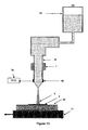
- Figure 1 shows an electrostatic spraying apparatus 1.
- An emitter tube 2 is capable of holding a liquid 3 to be electrosprayed.
- the tube 2 has a circular aperture or opening 29 from which the liquid 3 can be sprayed.
- the tube 2 acts as a liquid reservoir for the liquid 3.
- the liquid 3 is a low-conductivity or substantially non-conductive, i.e. substantially insulating, liquid.
- the liquid 3 may be a conductive liquid.
- the example provided below discusses the use of a substantially non-conductive liquid.
- An emitter tube 2 is capable of holding a liquid 3 to be electrosprayed.
- the tube 2 has an aperture or opening 29 from which the liquid 3 can be sprayed.
- the aperture is preferably circular.
- the tube 2 acts as a liquid reservoir for the liquid 3.
- the liquid 3 is a low-conductivity or substantially non-conductive, i.e. substantially insulating liquid.
- the substantially non-conductive liquid preferably has a conductivity of less than 10 -8 S/m, and may have a conductivity less than 10 -6 S/m.
- the liquid 3 may be a dielectric liquid.
- substantially non-conductive and insulating should be taken to mean a liquid with low conductivity of less than 10 -6 S/m, or optionally, less than 10 -8 S/m.
- An electrode in the form of a needle 4 is in contact with the liquid 3 to be sprayed.
- the needle 4 has a pointed end 4a tapered to a point.
- the pointed end 4a is adjacent to the opening 29 in the tube.
- the needle 4 is aligned with a longitudinal axis of the tube 2, and the pointed end 4a centred on the opening 29.
- the needle 4 is preferably made of metal.
- the pointed end 4a can emit positive or negative charges into the liquid 3 when a voltage is applied to the needle 4.
- the charges may be electrons (negatively charged) or made by capturing electrons (positively charged).
- the injection of charges into the liquid 3 can be considered to be a charging current.
- a substrate electrode 10 is positioned at an appropriate distance from the opening 29 of the emitter tube 2, typically of the order 1mm.
- the substrate electrode 10 is a solid square block of dimensions 2cm x 2cm by 0.5cm thickness, which is aligned with a longitudinal axis of the emitter tube 2.
- the substrate electrode 10 is grounded.
- the high voltage power supply 5 can provide a constant voltage (i.e. DC) to the liquid.
- the voltage provided can be varied to a selected value.
- a collector substrate 9 is placed on top of the substrate electrode 10.
- the collector substrate 9 receives the droplets of pulsed electrospray from the emitter tube 2.
- a computerised high precision translation stage 11 supports the collector substrate 9 and substrate electrode 10, and can move the electrode 10 perpendicularly to the direction of spray.
- the substrate surface may be coated with a pre-assembled monolayer of particles or molecules, and/or is coated with a pre-assembled sub-monolayer of particles or molecules.
- the substrate may be an insulator, a semiconductor, or a conductor.
- the substrate may in particular be silicon.
- the emitter tube 2, substrate electrode 10 and collector substrate 9 may be housed in a grounded stainless steel vacuum chamber to allow the pressure of surrounding gas to be varied, and in particular, reduced.
- the liquid 3 has a meniscus at the opening 29, the meniscus oscillating during electrospray.
- the meniscus may be in the form of a cone extending below the opening 29, as shown in Figure 1 .
- the oscillating liquid meniscus and the electrostatically produced droplets may be observed by a high speed charge coupled device (CCD) camera 7, illuminated by a cold light source 6.
- CCD charge coupled device
- the amount of charge injected into the fluid may be measured by a current monitoring device 12 connected to the emitter tube 2, in order to measure the current through the liquid.
- the electrostatic spray apparatus 1 is an unforced system, meaning that there is no pump or valve connected between the aperture 29 and the liquid reservoir when the apparatus is in use.
- the liquid flow from the reservoir is induced only by electrostatic forces.
- the electrostatic forces are generated by the injected charges within the fluid and the electric field present both at the surface of the fluid and within the fluid itself due to the free charges.
- the electrostatic spray apparatus 1 is configured to spray liquid 3 in discrete pulses, one or more pulses of liquid 3 being sprayed within a period in which voltage is applied to the needle 4.
- the pulses of spray occur automatically when the apparatus 1 is configured appropriately and are not directly generated by starting and stopping the applied voltage.
- liquid viscosity, electrode and emitter geometry are selected so that the forces required to electrostatically pump the liquid at a flowrate close to the minimum stable spray flowrate are not too large.
- the electric field strength or charging current is also selected based on liquid viscosity, electrode and emitter geometry. The electric field strength is chosen such that electrostatic spraying occurs in pulses, without a constant corona discharge. For a specific emitter aperture diameter, or hydraulic resistance, for a large liquid viscosity the electric field strength or rate of injected charge may be higher. For a lower liquid viscosity, a lower charging current may be used.
- Room temperature conductivities may range from a negligible conductivity up to 10 -6 S/m.
- Low conductivity cryogenic liquids such as liquid nitrogen, liquid ammonia, liquid hydrogen or liquid oxygen may also be used. Viscosities from 1 x 10 -4 to 100 Pa.s may be used.
- the electrostatic spraying apparatus 1 may be used as a printer, in order to spray an ink or print onto chips or substrates.
- the electrostatic spray apparatus 1 has the particular advantages that the starting and stopping of the liquid pulses can be very accurately controlled. This is because liquid only flows from the capillary exit and emitted from the tube 1 when charge is injected into the fluid 3.
- the charge can be injected into the low-conductivity or insulating fluid in a number of ways, including but not limited to injection from a sharp metal electrode at high voltage, from a piezoelectric charge injection device or a triboelectric charging mechanism.
- the starting and the stopping of the charge injection process can be very accurately controlled.
- the discrete pulses of ejected fluid are produced whilst a constant, i.e. non-pulsed, charging current or electric field is applied.
- the amount of liquid in each sprayed pulse is independent of the time for which the electric field or charging current is applied for.
- the constant electric field or charging current can be switched on and off to control when the discrete pulses should be emitted, and whilst the electric field or charging current is switched on the apparatus 1 emits a series of electrostatic spray pulses.
- the switching on and off of the electric field or charging current does not itself directly cause the pulses.
- the apparatus is configured such that when a constant electric field or charging current is applied it is in a mode which automatically generates pulses.
- the pulses of electrostatic spray are formed independently of any mechanical controlling means or electric field or charging current control means. This provides very consistent and uniform pulses, i.e. droplets, of electrostatically sprayed fluid.
- the electrostatic spray apparatus 1 additionally has the advantage that each spray pulse occurs as a discrete jet, each jet containing a small and predictable volume of liquid. If there is relative movement between the tube and a surface being sprayed, then the surface will receive a series of discrete dots, which may be spaced from one another. The provision of series of dots may be advantageous for printing or other applications. This is preferably achieved by movement of the surface being sprayed, but may also be achieved by movement of the emitter.
- the electrostatic spray apparatus may generate a pulsed electric field or charging current.
- Each pulse of electric field or charging current may contain one or more pulses of sprayed fluid.
- the electrostatic spray pulse will generally not start at the start of the electric field or charging current pulse, and will generally not finish when the electric field or charging current pulse finishes.
- the pulses of spray are independent of the pulse length of the applied electric field or charging current applied.
- the volume emitted by the electrostatic spray pulse or pulses will therefore depend on the number of electrostatic spray pulses occurring in the electric field or charging current pulse, and are not directly related to the length of the electric field or charging current pulse. This allows a tolerance in the length of the electric field or charging current pulse, without affecting the quantity of liquid emitted in the spray pulse.
- the electric field or charging current can be applied in pulses to the needle 4. Whilst the electric field or charging current is applied, the electrostatic spray can occur in pulses at pre-determined frequency but will generally not start immediately, i.e. the device will not automatically spray as soon as the electric field or charging current is turned on. The on time for each pulse of electric field or charging current must be long enough to allow one spray pulse to be emitted but short enough to prevent two (or the required number) of electrostatic spray pulses being emitted.
- the electrode and/or substrate can be moved, in order to apply sequential spray pulses to a different location on the substrate. Any number of pulses of liquid can be sprayed before the electric field or charging current is reduced to inhibit further pulses. Increasing the charging current will increase the frequency of pulses, allowing further control of the deposition of the liquid.
- This system 1 does not have a reservoir separate from the emitter tube.
- the tube 2 itself stores the liquid 3 to be sprayed.
- This embodiment allows the deposition of the liquid 3 onto the substrate 9 by the correct application of potential from the supply 5.
- liquid may be stored in a reservoir in fluid connection with the emitter tube.
- the distance between substrate 9 and emitter 2 can be varied to make the deposition area smaller or larger. Depending on the level of charge on the sprayed droplets, the sprayed droplets 8 may spread out as it travels away from the emitter 2, and so a larger distance between the substrate 9 and emitter 1 can provide a larger deposition area.
- the electrode 10 and/or collector substrate 9 are preferably placed on a translation stage 11, which may be computer controlled.
- the translation stage 11 provides relative movement between the electrode 10 and/or substrate 9 and the sprayed droplets 8 in order that the sprayed droplets 8 are deposited over a selected area of the substrate 9.
- the emitter tube 2 is formed of uncoated borosilicate glass capillary with an outer diameter of 2mm and inner diameter of 0.86mm which tapers to an opening 29 of 42 ⁇ m diameter.
- the electrospray apparatus 1 was used with a fluid being a carbon loaded oil based ink with conductivity of approximately 10 -12 S/m and viscosity of 10mPa.s as the liquid 3 to be sprayed.
- the collector substrate 9 used was high quality photographic paper which was placed upon the steel substrate electrode 10 which was at ground potential.
- the frequency of droplet emission could be determined by post-deposition imaging of the substrate.
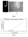
- FIG. 2A An example image of the pulsing ink spray emanating from the capillary exit is shown in Figure 2A .
- FIG. 2B An example micrograph of the collector substrate 9 showing a series of lines of deposited dots of ink at differing emission frequencies is shown in Figure 2B .
- the speed of movement of the substrate was selected to be 50mm/s using the computer controlled translation stage 11.
- the frequency of emitted liquid pulses was varied by altering the applied voltage to the metal injector electrode 4.
- the droplet emission frequency was found to increase from approximately 300Hz at 900V to around 80kHz at an applied voltage of 4.0kV as shown in the graph in Figure 3 . Over the range 900 to 4000V the frequency of spray pulses and droplet emission continued to increase and no stable cone-jet spraying regime was observed. At voltages above 4.0kV an electrical discharge began to occur with periodic sparking.
- the liquid volumes emitted in each electrostatic spray pulse were calculated to be of the order 1-3 picoliters.
- Figure 4 shows the effect of varying emitter/nozzle size on the range of drop emission frequencies achievable due to changes in the applied field. From the figure it is shown that the minimum and maximum drop emission frequencies are generally lower when a larger emitter/nozzle exit diameter is used.
- the liquid is the same carbon loaded oil based ink as described above, including data from spraying with larger nozzles than the 42 micron one previously discussed.
- FIG. 5 shows a modification of the illustrative example of the electrostatic spray apparatus shown in Figure 1 .
- the electrospray apparatus 21 shown in Figure 5 comprises two emitter tubes 13a, 13b, each tube 13a, 13b substantially the same as tube 2 described above. Alternatively, any number of emitters may be used.
- the first tube 13a contains a first liquid 15a to be sprayed.
- the second emitter tube 13b contains a second liquid to be sprayed.
- a first pointed electrode 4b is located within the first emitter tube 13a, and aligned with the longitudinal axis of the tube 13a.
- a second pointed electrode 4c is located within the second tube 13b, and aligned with the longitudinal axis of the second emitter tube 13b.
- a power supply is connected to the first electrode 4b.
- the same power supply 14, or a different power supply is connected to the second electrode 4c.
- the electrospray apparatus 21 further comprises a substrate 9a, on to which the liquids 15a, can be sprayed.
- the substrate 9a is mounted on a electrode 10a, which is at ground potential.
- the electrode 10a may be connected to the or each power supply.
- the substrate 9a and grounded electrode 10a may be mounted on a translation stage 11a, for moving the substrate 9a whilst at a constant distance from the emitter tubes 13a, 13b.
- Each of the emitter tubes 13a, 13b has an opening through which the liquid 15a, can be sprayed.
- a second power supply 14 is connected between an electrode 10 and the immersed metal electrode 4B.
- Figure 5 shows two emitter tubes, however more than two tubes can be used together.
- the tubes may be arranged in a two-dimensional array.
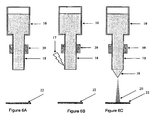
- FIGS. 6A, 6B, 6C show a further illustrative example of the electrostatic spray apparatus.
- An emitter tube 18 is in the form of a capillary tube connected to an insulating fluid reservoir 16 which contains the liquid to be sprayed.
- a triboelectric charge 17 is transferred to the capillary tube 18 to initiate a spraying of the fluid.
- the duration of the fluid spray and nature of the sprayed pulses is dependent on the amount of injected charge.
- the liquid to be sprayed was Dow Corning FS1265 silicone oil.
- An opening is provided in the capillary 18 through which electrospray can occur.
- no pointed electrode is present in the capillary 18.
- This entire system was held by an insulating support 39 below which was an optional insulating substrate 22.
- a section of rubber 17 was then used to transfer charge to the silica capillary 18 triboelectrically, as shown in Figure 6B . Once the charge was transferred to the silica capillary a cone 19 and spray 20 emanated from the capillary as shown in Figure 6C .
- the frequency of droplets sprayed during or after application of a triboelectric charge may change as the charge is dissipated.
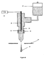
- Figure 8 shows a preferred embodiment of the electrostatic spray apparatus of the present invention wherein the emitter tube 30 is in the form of a capillary tube connected to a fluid reservoir 24 which contains the liquid to be sprayed.
- the charging current is delivered piezoelectrically by the piezoelectric charging device 26 to a metal injector electrode 28 which is at least partially immersed in the fluid to be sprayed.
- the field generated at the needle tip 32 due to the piezoelectrically generated charge causes the fluid to flow and exit the capillary tube 30 in the form of a pulsed spray of fluid.
- the counter electrode 34 may be a substrate to receive the fluid or may include an open aperture to allow the fluid exiting the capillary tube to be sprayed into the surrounding gaseous atmosphere or vacuum.
- the liquid to be sprayed is Dow Corning FS1265 silicone oil.
- the liquid was held in an insulated reservoir 24, which is preferably unpressurized.
- an insulated emitter tube in the form of a silica capillary 30.
- the capillary is held by an insulating support.
- An electrode 28 with a sharp pointed geometry section 32 extends into the capillary 30 and is at least partially immersed in the fluid to be sprayed.
- a piezoelectric charging device (PCD) 26 was electrically connected to the electrode 28. Upon activation of the piezoelectric device 26 charge was delivered to the fluid through the electrode 28 resulting in pulses of spray 35
- This embodiment may comprise an electrode having an aperture 34, the spray 35 ejected through the aperture 34.
- the charging current delivered to the fluid by the PCD 26 is sufficiently high, a stable cone-jet spray of fluid can be emitted from the capillary 30.
- the arrangement shown in Figure 8 may be used to deliver fluid to a substrate (not shown in Figure 8 ) located on the other side of the aperture to the emitter tube 30.
- this arrangement may be used to deposit ink onto paper or other printable material without requiring an electrode on its underside, i.e. there is no requirement for the printable material to be placed between the emitter tube 30 and the electrode 34.
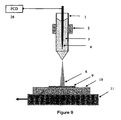
- Figure 9 shows a further example, substantially as described with respect to Figure 1 .
- a PCD 26 as described for Figure 8 is used to supply the charges.
- Figure 10 shows a modification to the electrostatic spray apparatus of the present invention shown in figure 8 wherein the charge injection electrode is in the form of a metal coating 40 on the outer surface of the capillary tube 38 which contains the liquid to be sprayed.
- the charging current is delivered piezoelectrically by the piezoelectric charging device 26 to the metal injector electrode 40 which is at least partially in fluid communication in the liquid to be sprayed.
- the field generated due to the piezoelectrically injected charge causes the fluid to flow and exit the capillary tube 38 in the form of a charged liquid spray.
- the collector substrate 9 and substrate electrode 10 may be placed on a computer controlled translation stage 11 to allow relative movement between the collector surface and the liquid spray.
- Figure 11 shows a modification of the example of the electrostatic spray apparatus shown in Figure 1 or Figure 5 .
- the emitter is not in the form of a capillary tube, but is formed from any material 42 that can define a reservoir to store a liquid 46.
- An orifice is formed in the reservoir, from which the liquid may be sprayed.
- This embodiment may be microfabricated.
- a high voltage power supply 48 may be connected to the material 42 or a sharpened metal electrode 44 located in the reservoir in order to inject charge into the fluid 46.
- the embodiment of Figure 11 functions in the same manner as Figures 1 and 5 .
- any of the embodiments described above may have at least the emitter and substrate located in a vacuum chamber, from which air is substantially evacuated.
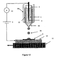
- Figure 12 shows a further example of an electrospray apparatus.
- the emitter tube 2, liquid 3, pointed electrode 4 and power supply 5 are substantially as shown in Figure 1 or figure 5 or figure 11 .
- the substrate 9, grounded electrode 10 and translation stage 11 are also as described above.
- a tube 50 is arranged co-axially around the emitter tube 2, an opening of the emitter tube 50 surrounding the opening of emitter tube 2.
- the tube 50 contains a second fluid 54, such that the opening of tube 2 through which electrospray occurs from emitter tube 2 is located within the second fluid 54.
- the second fluid 54 is different to the electrostatically sprayed liquid.
- the second fluid 54 may be either a liquid or a gas, and is contained within a container 52.
- the container 52 may be sealed or connected to a reservoir of fluids.
- the second fluid 54 is preferably immiscible with the fluid to be electrostatically sprayed, but may be partially miscible with the fluid to be sprayed.
- the second fluid 54 may be static or flowing.
- the second fluid 52 is preferably immiscible with the fluid to be electrostatically sprayed 3, but may be partially miscible with the fluid to be sprayed.
- the second fluid 52 may be static or flowing.
- Spraying through the second fluid allows drops of the first fluid to be produced within a coating or film of the second fluid 56. This can allow the atomisation of encapsulated fluids into gaseous, liquid or vacuum environments or the deposition of encapsulated liquid drops onto the receiving substrate material 9.
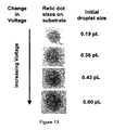
- Figure 13 illustrates the variation of emitted drop volume of a carbon loaded oil based ink due to changes in the applied field to the injector electrode in a similar arrangement to that shown in figure 1 .
- the frequency of droplet emission and the volume of each droplet were increased over the voltage range shown.
- FIG 14 shows a further illustrative example.
- An emitter tube 60 contains a first liquid 61 to be electrosprayed.
- the tube 60 has a pointed electrode connected to a power supply 68, substantially as described for Figure 1 .
- the emitter tube 60 has an opening 65 through which the pulses of electrospray of liquid 61 are emitted.
- the opening 65 is located within a container 62.
- the container 62 contains a second fluid 64 different to the electrostatically sprayed liquid.
- the second fluid 64 may be either a liquid or a gas.
- the container 64 may be sealed or connected to a reservoir of fluids.
- the second fluid 64 is preferably immiscible with the fluid to be electrostatically sprayed, but may be partially miscible with the fluid 61 to be sprayed.
- the second fluid 64 may be static or flowing.
- a substrate and grounded electrode, and/or translation stage as previously described may also be located within the container 62.
- Spraying through the second fluid allows drops of the electrostatically sprayed liquid to be dispersed controllably in the second fluids. This allows the formation of an emulsion, for example an oil/water emulsion or a nano-emulsion. It may also provide for the formation of particles having the electrostatically sprayed liquid contained within a solidified shell of the second liquid. Additionally, a volatile liquid may be sprayed in an involatile second liquid.
- All of the described embodiments are configured to produce pulses of electrospray whilst charges are injected into the substantially non-conductive or conductive liquid or fluid to be electrosprayed.
- the pulses are not directly caused by the starting and stopping of the injection of charges, but are inherent in the configured system.
- Figure 1B shows a further illustrative example of an electrospray apparatus. This apparatus is configured to spray a conductive liquid.
- a capillary emitter tube 70 contains liquid 74 to be sprayed.
- a high voltage power supply 79 is connected between an extractor electrode 78 and the emitter tube 70. An electric potential may be applied to the conductive surface of the emitter 70 by a conducting fitting 72. The high voltage power supply 79 provides a potential difference between the electrode 78 and the emitter 70.
- the extractor electrode 78 is held at an appropriate distance from the emitter tip. On a side surface of the electrode 78 facing the emitter tube 70 a target substrate 77 can be placed.
- the substrate may be coated with a pre-assembled monolayer of particles or molecules, and/or is coated with a pre-assembled sub-monolayer of particles or molecules.
- the substrate may be an insulator, a semiconductor, or a conductor.
- an electric potential is generated by the supply 79, such that liquid is ejected from the tube 70 as a jet or spray 76 in pulses.
- the spray 76 impacts on substrate 77.
- a computerised high precision translation stage 80 supports the substrate 77 and electrode 78, and can move the electrode 78 perpendicularly to the direction of the spray 76.
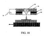
- Figure 18 shows a different example of the electrospray apparatus than shown in Figures 1 and 1b .
- an emitter is not in the form of a capillary tube, but is formed from any material 85 that can define a reservoir to store a liquid 86.
- An orifice is formed in the reservoir, from which the liquid may be electrosprayed. This embodiment may be microfabricated.
- a layer of material 87 is sandwiched between the material 85 and a layer 89.
- the layers of material 87, 89 define a recess around the orifice.
- the materials 85, 89 are preferably electrically conductive, or have electrically conductive elements embedded.
- the material 87 is preferably non-electrically conductive.
- a high voltage power supply 79 is connected to the material 85, and is preferably also connected to the material 89.
- the high voltage power supply 79 is configured such that an electric field is generated in the liquid 86, to cause pulses of electrospray as described above. This illustrates an example of an integrated electrode.
- liquid viscosity, electrode and emitter geometry are selected so that the forces required to electrostatically pump the liquid at a flowrate close to the minimum stable spray flowrate are not too large.
- the electric field strength or charging current is also selected based on liquid viscosity, electrode and emitter geometry. The electric field strength is chosen such that electrostatic spraying occurs in pulses, without a constant corona discharge. For a specific emitter aperture diameter, or hydraulic resistance, for a large liquid viscosity the electric field strength or rate of injected charge may be higher. For a lower liquid viscosity, a lower charging current may be used.
- the volume of liquid in each drop has been found to increase as the charging current or electric field is increased over part of the range of voltages at which pulses of electrospray occurs. For example, increasing drop volume with increasing voltage has been found to occur between 900 V and 3000 V applied. Increasing the charging current or electric field thus increases both the frequency of emitted droplets and the volume of liquid in each droplet.
- Apparatus based on Figure 1 , 1b or 18 may have a plurality of emitters, which may be arranged in an array. A separate reservoir may be provided, in fluid connection with the emitter.
- the emitter may not be in the form of a capillary tube, but may be formed from any material that can define a reservoir to store a liquid.
- An orifice is formed in the reservoir, from which the liquid may be sprayed.
- This embodiment may be microfabricated.
- a high voltage power supply or other means for charge injection may be connected to the material or a sharpened metal electrode located in the reservoir in order to inject charge into the fluid.
- the emitted drop volume of a liquid varies due to changes in the applied field to the injector electrode.
- both the frequency of droplet emission and the volume of each droplet were increased, over part of the range at which electrospray occurs.
- the volume of each drop may reach a peak, and then decrease.
- the drop volume relationship to applied voltage may be dependent on the properties of the liquid and emitter geometry.
- the electrospray pulses can be accurately controlled using the apparatus of Figure 1 , Figure 1b or 18 . It may be required to deposit one drop, or a pre-determined number of drops, at the same point in the substrate. It is therefore necessary to control the volume of liquid which is electrosprayed before ceasing electrospray to allow movement of the translation stage. Alternatively, it may be required to control the rate at which electrospray occurs onto a moving or stationery translation stage.
- Figures 3a and 3b show a first mode of the invention.
- the liquid to be electrosprayed can be either a conductive or non-conductive liquid, which is the case for all of the described modes.
- the apparatus used will be based non the appropriate one of Figure 1 or 1b .
- the electrospraying apparatus applies a voltage or charging current to the liquid.
- the voltage applied switches between two voltages or charging currents, preferably repeating the cycle at a rate of 5kHz. Each of the two voltages may be applied for an equal amount of time, being 0.0001 seconds in that case, or one of the two voltages may be applied for a longer period of time than the other.
- a first voltage is applied during a period.
- the first voltage is selected below a minimum threshold for electrospray pulses to be emitted. Therefore, no pulses are emitted during the first period.
- An example voltage is 350 v.
- the applied voltage is switched to a higher voltage.
- the second higher voltages is constant throughout the second period and causes six droplets of electrospray to be emitted from the apparatus at a constant frequency.
- An example second voltage is 400 v.
- the voltage then switches back to the first voltage, and the cycle repeats.
- the voltages or charging currents in the first and second periods are preferably each substantially constant whilst applied to form a square wave, or alternatively may be in the form of a saw tooth or triangular or sinusoidal wave.
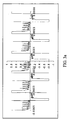
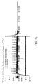
- Figure 3b shows an enlarged view of the first period and the second time period.
- the pulses of electrospray are indicated by the peaks 114. Note that the saturated squared off positive and negative currents shown do not represent emitted pulses of electrospray, and are merely caused by the change in applied voltage.
- the lengths of the periods are different, in particular, the length of the non/pulse emitting" period is longer than the "off" period. Alternatively, the lengths of periodsmay be the same.
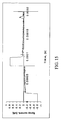
- Figure 15 shows a variation of the first aspect of the invention.
- the applied voltage cycles at a frequency of 5kHz between a first voltage and a second voltage.
- the first voltage is applied during a period.
- the first voltage is selected such that no electrospray pulses are emitted.
- the second voltage is applied in the second period.
- Figure 3 shows how selection of voltage will affect the frequency of emitted droplets.
- the second voltage is selected such that one electrospray pulse is emitted during this time. This cycle may then repeat, alternating between the first and second voltages.
- Figure 16 shows switching between two voltages, as described above.
- a first voltage is applied which results in no electrospray droplets being emitted.
- a second voltage is applied in a second period. The second voltage is selected to cause electrospray to occur at a frequency which results in three electrospray droplets to be emitted during the period 132.
- the electric field or charging current is reduced to a non-zero strength when no electrospray is to be emitted.
- the voltage may be reduced by less than 100V, and preferably between 20 to 50V, when moving from a period in which alectroopray is emitted to a period when electrospray is not emitted.
- the electric field or charging current may be substantially zero when no electrospray is to be emitted.
- the time-varying electric field or charging current may be produced in all embodiments by generating a d.c. (or constant) electric field or charging current component. A generally smaller time-varying component is also generated, and superimposed on the constant component.
- the time-varying electric field or charging current has been described as a square wave, in which the strength of the electric field or charging current alternates between two values. Both of the alternating values are preferably non-zero, even if no electrospray is emitted in one of them.
- the waveform of any embodiment may alternately be an irregular, or not be a constant over even part of the waveform. In particular, the waveform may be the form of a sinusoidal-wave, saw tooth or triangular-wave.
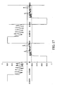
- Figure 17 shows another aspect of the present invention.
- a constant first voltage is applied to the liquid.
- the first voltage is selected such that droplets are emitted at a frequency which results in two droplets being emitted in the first time period.
- the apparatus switches to a second voltage, which is applied during a second time period.
- the second voltage is selected to be higher such that six electrospray pulses are emitted during the second time period.
- the apparatus cycles through the first and second voltages at a rate of 5Khz.
- the first and second time periods are equal in length, being 0.0001 seconds each.
- the cycle continues by repeating the first voltage in a third period, during which two electrospray pulses are emitted.
- the rate of emission of pulses dependent on the voltage or charging current applied, is therefore different in the first and second periods.
- the first and second time periods as described above have been shown as being an equal length of time. Alternatively, the first and second time periods may be different lengths of time.
- the voltage for each time period and the length of time it is applied for can be freely varied to deliver the required volume of liquid at the required rate, or with pre-determined periods of time with no electrospray.
- the apparatus may cycle through two, three or more periods of time, each period having a different voltage applied.
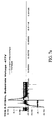
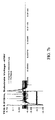
- Figures 7a , 7b and 7c show another aspect of the invention, which provides an alternative means of control .
- the on-time of the voltage applied to the liquid can be varied.
- a constant voltage is applied in order to emit electrospray pulses.
- the voltage or charging current is applied for a selected length of time to allow the required number of pulses has been emitted.
- the voltage is then reduced such that further electrospray pulses are not emitted.
- the voltage can then be switched on again, and the cycle repeated.
- the voltage may be reduced just below a minimum threshold value such that no electrospray is emitted, or may be reduced to zero.
- the electric field or charging current is reduced to a non-zero strength when no electrospray is to be emitted.
- the voltage may be reduced by less than 100V, and preferably between 20 to 50V.
- Figure 7a shows the voltage being switched on for a time period.
- the time period is selected such that there is only time for one pulse to be emitted.
- the voltage is then reduced for the remainder of the cycle such that no further pulses are emitted.
- Figure 7b shows the voltage switched on for a time period. The time period is sufficient to allow three pulses to be emitted.
- Figure 70 shows the voltage being switched on for a time period, sufficient for fourteen droplets to be emitted.
- the voltage in this aspect is selected depending on the use of the electrospray, in order to give a reasonable rate of spray for that application, which can be accurately controlled.
- the apparatus may operate in the third mode in a cycle.
- the cycle may have a constant period, which may be chosen to be longer than the expected longest length of time for which electrospray is wanted to be emitted. Whilst the electric field or charging current strength is above the threshold strength, electrospray pulses will occur. The length of time for which the electric field or charging current strength is above the threshold strength can be varied.
- a duty cycle of a waveform can be considered as the proportion of the cycle which the waveform is 'high' or 'on', and so the duty cycle of the waveform will be variable depending on the length of time for which electrospray occur compared to when no electrospray pulses are emitted.
- the means for varying the strength of the electric field or charging current in a cycle of constant period may provide a variable duty cycle.
- the apparatus may operate in a mode in which the voltage, and length of time that voltage is applied for, can both be varied in order to control the emission of electrospray droplets.
- Electrospray according to any of the embodiments above has many uses. Some of the possible uses, and how the electrospray is optimised for them, will now be described. These uses and methods of use apply to all embodiments.
- the present invention may be used as a printer, as an example of a direct writing process.
- the liquid sprayed may be a suspension of gold nanoparticles, or may be a conductive ink based on silver nitrate.
- metallo-organic decomposition inks may be used, for example comprising silver neodecanoate dissolved in toluene.
- the substrate could be silicon, acetate, glass, plastics, papers or other materials.
- Such conductive inks may have a viscosity of around 10cP.
- the present apparatus would preferably use a nozzle diameter of 10 to 50 ⁇ m.
- Other screen printable inks have a viscosity greater than 100cP, which may be used in the present method with a nozzle diameter of greater than 100 ⁇ m.
- plastic substrates for electronics allows-creation of electronic circuits on a flexible plastic substrate.
- a plastic substrate presents the problem that it may have a rough surface and a low melting temperature. These problems can be overcome by solution processing, requiring the materials to be printed in solution form onto the plastic at a reasonable temperature. This technology may be able to print the materials desired for this application. Conductive tracks may be printed as described above on the plastic substrate.
- Light-emitting Polymers e.g. PEDOT - Poly(3,4-ethylenedioxythiophene)
- Conducting Polymers e.g. PEDOT - Poly(3,4-ethylenedioxythiophene)
- These materials may be mixed in water or a dielectric liquid.
- the appropriate apparatus described above may be used depending on the conductivity to be electrosprayed, i.e. whether it can be considered conductive or non-conductive.
- the nozzle diameter can be selected to suit the size of the features required and the solution viscosity.
- the nozzle diameter may be 5 or 10 ⁇ m for small features and a viscosity similar to water.
- the apparatus may be used to print Thin Film Transistor (TFT) screens.
- the substrate used may be glass, and a conductive liquid may be electrosprayed.
- An integrated electrode may be used, as shown in Figure 18 .
- the fabrication of screens may utilise any of the features described for maskless lithography, conductive tracks or plastic electronics.
- the apparatus and method can be used for the purpose of tissue engineering, for example by spraying proteins in aqueous solutions.
- the proteins may range from simple amino acids to large non-covalently bound macromolecules, such as proteosome.
- the mass of the proteins may extend up to around 1Mda, and this also allows some viruses to be electrosprayed.
- Water may be used as the solvent, since it has a suitable viscosity.
- a wide range of nozzle diameters may be used, and preferably nozzle diameter 10 to 30 ⁇ m may be used.
- the substrate may be a scaffold made from biodegradable polymers (e.g. PLGA) with a scale of about 10 ⁇ m.
- the apparatus may use an integrated electrode.
- the protein sprayed may be a functional protein such as fibronectin, albumin or collagen. This would allow cell growth and migration to be controlled on a micro-scale on the scaffold.
- the present apparatus may be used to create lipid bilayers, or scaffolds for proteins.
- the apparatus may be used for accurate dispensation of liquids, for example, for drug discovery purposes.
- the apparatus may be used in place of a nebuliser, for example to vaporise a liquid medicine or liquid containing a biologically active agent to produce droplets in the preferred region of 0.4 to 6 microns.
- a nebuliser for example to vaporise a liquid medicine or liquid containing a biologically active agent to produce droplets in the preferred region of 0.4 to 6 microns.
- the vaporised liquid in the form of a mist can then be inhaled by a user.
- the apparatus may be used to vaporise a liquid medicine or liquid containing a biologically active agent. This vapour may then be administered topically or transdermally to a user.
- the apparatus may be used in combination with a mass spectrometer.
- the apparatus is suitable for dispensing very small quantities of molecules, e.g. into a mass spectrometer.
- the substrate may be glass or plastic.
- the apparatus may be configured to dispense femtolitre volumes to high picolitre volumes of aqueous solutions. The solutions may contain the molecule to be tested.
- the present apparatus and method may be used for spraying analytes onto a lab on a chip.
- the present apparatus may be used for rapid prototyping, or for the production of biological micro arrays.
- the method can also be used to micro-pipette solutions, or create micro-arrays.
- the apparatus of the present invention may be used for electrospraying proteins or other analytes onto a biosensor.
- the apparatus of the present invention may be used to transfer a pattern onto a surface.
- Photolithography uses an etch mask which is often made of a polymer called a photoresist, in which the pattern is created by light exposure.
- the present invention can create etch masks either by printing etch resist materials directly onto the surface in the desired pattern, or by printing etchant or resist developer onto the surface to remove either the etch resist or the unwanted useful film from where its is not required.
- Printing etch resist materials may use polymers or waxes as the liquids to be electrosprayed. Such liquids are likely to be dielectric (i.e. non-conductive) and so apparatus based on Figure 1 may be used. A nozzle diameter of greater than 100 ⁇ m may be used.
- the substrate is preferably silicon, or maybe any other material. Etchants or developers are likely to be organic solvents with low viscosities.
- Metamaterials are artificially produced materials with a periodic or cellular structure often called a "super-lattice” or a “photonic crystal".
- the period of the cells must be comparable to the wavelength of light it interacts with. For visible light, a wavelength of less than one micron would be required.
- the technique of the present invention may be able to achieve printing on this scale.
- Optical devices can be fabricated from polymers with features on the micron scale. Microfabrication of waveguides and mirror assemblies may be achieved using lithography material deposition and etching processes as discussed above.
- the liquid to be electrosprayed is preferably a polymer, onto a silicon or glass substrate.
- the apparatus of the present invention may be used to fabricate optical devices, such as gratings or holograms.
- the apparatus for the present invention may be used to manufacture screens comprising organic Light Emitting Diodes(OLEDs) or for a Liquavista (RTM) screen.
- OLEDs organic Light Emitting Diodes
- RTM Liquavista
- the apparatus may also be used in the manufacture of sensors, or may be used to print images, using ink or any other liquid as the liquid to be sprayed.
- the invention may be used in manufacturing, for positioning adhesives, patterning or making electronic components.
- the electrospray apparatus may be used as a printer, in order to spray inks or print onto chips or substrates.
- the uses and applications described are applicable to any apparatus or method utilising inherently pulsed electrospray, and is not limited to the example apparatus or methods of operation described.
- the uses and applications are applicable when the electric field or charging current strength is reduced to zero (or to a non-zero value) in order to pause electrospray.
- the apparatus and method of the present invention may be used to spray a plurality of droplets at one point on a substrate, and then provide relative movement between the substrate and emitter to continue spraying at a different point on the substrate.
- the relative movement may occur whilst electrospraying is paused by reducing the field strength below a threshold level.
- the apparatus and method may also be used to spray only one droplet at any point on the substrate, which may be achieved by continuous relative movement of the substrate or emitting only one droplet at a time, and then moving the substrate whilst electrospraying is paused by reducing the field strength below a threshold level.
- the substrate may be paper, silicon, semiconductor, insulator, conductor, card, food, packaging, plastics and skin.
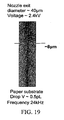
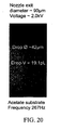
- Figures 19-21 show the results of drop deposition, shown as photographs, on various example substrates. These figures provide an indication of the parameters (voltage, capillary diameter) used to produce various results including drop volume and frequency.
- the voltage may be substantially independent of nozzle or emitter exit diameter.
- the emission frequency and in particular the maximum emission frequency may be dependent on nozzle or emitter exit diameter. Therefore, varying this diameter may be used to vary this parameter.
- Figures 19-21 provide examples of this dependence.
Landscapes
- Engineering & Computer Science (AREA)
- Analytical Chemistry (AREA)
- Physics & Mathematics (AREA)
- Chemical & Material Sciences (AREA)
- Microelectronics & Electronic Packaging (AREA)
- Manufacturing & Machinery (AREA)
- Plasma & Fusion (AREA)
- Immunology (AREA)
- Biochemistry (AREA)
- Pathology (AREA)
- Life Sciences & Earth Sciences (AREA)
- General Physics & Mathematics (AREA)
- Health & Medical Sciences (AREA)
- General Health & Medical Sciences (AREA)
- Electrostatic Spraying Apparatus (AREA)
- Application Of Or Painting With Fluid Materials (AREA)
- Automatic Analysis And Handling Materials Therefor (AREA)
- Electroluminescent Light Sources (AREA)
- Particle Formation And Scattering Control In Inkjet Printers (AREA)
Abstract
Description
- The present invention relates to an electrostatic spraying apparatus and a method of electrostatic spraying.
- In conventional electrostatic atomisation or electrospray techniques the surface of an electrolytic liquid, typically of conductivity greater than 10-8S/m, is charged by an applied electric field, typically of the order around 106 V/m. Spraying occurs when the electrostatic forces on the fluid surface overcomes the surface tension of the liquid. The most stable spraying regime is that of the cone-jet mode, in which the balance between electrostatic and surface tension forces creates a Taylor cone, from the apex of which a liquid jet is emitted. This stable cone-jet only occurs within a particular range of liquid flow rate and applied voltage. When the voltage and/or the flow rate are below that required for stable cone-jet then other spray regimes occur, including dripping, electrodripping and spindle mode.
- A particular electrospray method commonly used in electrospray ionisation mass spectrometry, as described in Int. J. Mass Spectrom. Ion processes 1994,136,167-180, is known as nanoelectrospray. A characteristic of nanoelectrospray is that the flow rate can be dictated by the voltage applied and the tube geometry, in particular the exit diameter. This has the advantage that electrospray can be achieved without the use of pumps or valves to force the liquid from a reservoir to the exit. The ability to controllably eject or deposit small volumes of fluid using this method has been identified in J. Aerosol Sci. 2007,38,315-324 as a promising technique for patterning surfaces with a range of fluids
- In electrostatic spraying of insulating fluids, with conductivity less than 10-8S/m, the intrinsic conductivity is not sufficient to produce a large enough surface charge under the applied voltage in a similar manner to that of conventional electrospray behaviour observed with fluids of higher conductivity as described above. However, it has been shown that if a particular electrode geometry, for example using a sharpened needle as the electrode immersed in the fluid, is used it is possible to inject charges into the insulating fluid to allow the liquid to undergo spraying and jetting as described in J. Appl. Phys., 1976,47,5,1964-1969. In this way it is possible to develop sufficient surface charge to spray the dielectric liquids in similar modes to that observed in conventional electrospraying. The mechanism of charge injection is not limited to a high voltage power supply and includes but is not limited to triboelectrically generated charge and piezoelectric devices.
- It is also known from J. Appl. Phys. 1998,64,4278-4284 that for insulating fluids when the voltage is lower than that required to produce a stable cone-jet type mode, the liquid meniscus may undergo oscillations between a quasi-stable cone-jet and a deformed drop. This results in a pulsed spray with the intermittent emission of fluid droplets from the liquid surface. The production of pulses required a constant fluid flow rate, provided by a pump or a pressurized fluid.
- In other known electrostatic atomisation or electrospray techniques, electrospray occurs continuously whilst a voltage or charging current is applied to the liquid to be sprayed. Control of the volume of liquid that can be electrosprayed is therefore relatively limited, since any variation in the time for which the voltage or charging current is applied directly affects the volume of liquid sprayed.
- The known method of electrostatic spraying of insulating fluid have the disadvantage that in order to start and stop the spray, it is necessary to start and stop the pumping method. It is not possibly to accurately control the starting and stopping of the pmnp. In such an apparatus, even if the electric field or charging current is switched off the pump will continue to deliver liquid to the tube exit or spry area, resulting in dripping. This means that fine control of the liquid spray is not possible.
-
US2006/0262163 describes an electrostatic suction type fluid discharge device that discharges material from a nozzle onto an insulating substrate using a bipolar pulse voltage. -
US2007/0101934 described an electrostatic suction type fluid discharge method and device for applying a conductive fluid onto a non-conductiva substrate. -
WO 01/71311claim 1. - According to a first aspect the present invention provides an electrostatic spray apparatus as described in
claim 1. - This has the advantage that the electrostatic spray apparatus provides reliable pulses of sprayed non-conductive liquid droplets which can be accurately started and stopped.
- According to a second aspect the present invention provides a method of electrostatic spraying as described in claim 13.
- Either positive or negative charges may be injected into the liquid or fluid.
- Optionally, the means for injecting charges into the liquid or fluid is a pointed conductor such as for instance a metal needle or pin, having a tapered or sharpened point. This aids charge injection especially for non-conductive fluids or liquids.
- Optionally, the point may be fully immersed within the liquid. The point may also be located within the emitter. The point may therefore not protrude through an aperture of the emitter. The emitter may be a cavity or capillary having an aperture or opening. The point may also be located inside the cavity and so without extending through the aperture of the cavity, i.e. before the aperture. This improves the charge injection thereby improving the regular nature and reliability of the pulses or emitted drops and
- also may reduce the occurrence of a jet or drops breaking up into smaller and more irregular droplets. This may be of particular importance for non-conductive fluids or liquids.
- This has the advantage that the electrostatic spray apparatus provides reliable pulses of sprayed liquid droplets forming an accurately controllable volume of sprayed liquid.
- Preferably, the strength of the time-varying electric field or charging current can be varied such that one or more pulses of electrospray are emitted during a first time period, and one or more pulses of electrospray are emitted during a second time period; wherein the rate of emission of pulses in the first time period is different to the rate of emission of pulses in the second time period.
- Preferably, the length of the first time period is substantially the same as the length of the second time period.
- Preferably, there is provided means for varying the length of time the strength of the electric field or charging current is above the threshold strength.
- Preferably, the strength of the electric field or charging current is substantially constant whilst above the threshold strength.
- Optionally, the method may be used for the manufacture of conductive tracks.
- Advantageously, the strength of the time-varying electric field or charging current varies such that one or more pulses of electrospray are emitted during a first time period, and one or more pulses of electrospray are emitted during a second time period; wherein the rate of emission of pulses in the first time period is different to the rate of emission of pulses in the second time period.
- Optionally, the method comprises varying the strength of the electric field or charging current in a cycle of constant period, the duty cycle when the strength is greater than the threshold value being variable.
- Embodiments of the present invention will now be described with reference to the figures, in which:
-
Figure 1 is schematic side elevation view of the apparatus according to an illustrative example which is not part of the invention; -
Figure 2A is a side view of a pulled glass nozzle during electrostatic spraying of a liquid according to a first aspect of the present invention; -
Figure 2B is a plan view of a substrate after having received an electrostatic spray of a liquid according to the first aspect of the present invention; -
Figure 3 shown a graph of the dependence of drop emission frequency on the applied voltage for a particular injector electrode and nozzle geometry using a first aspect of the present invention; -
Figure 4 shows a graph of drop emission frequency range achievable with different nozzle dimensions when spraying in accordance with the first aspect of the present invention; -
Figure 5 is schematic side elevation view of an apparatus according to a second illustrative example which is not part of the invention; -
Figures 6A, 6B and 6C are schematic side elevation views of an apparatus according to a third illustrative example which is not part of the invention; -
Figure 7 is an image of an electrostatic spray of a liquid produced using the apparatus according to an embodiment of the present invention; -
Figure 8 is a schematic side elevation view of an apparatus according to a preferred embodiment of the present invention; -
Figure 9 is a schematic side elevation view of an apparatus according to a fourth illustrative example which is not part of the invention; -
Figure 10 is a schematic side elevation view of an apparatus according to a fifth illustrative example which is not part of the invention; -
Figure 11 is a schematic side elevation view of an apparatus according to a sixth illustrative example which is not part of the invention; -
Figure 12 is a schematic side elevation view of an apparatus according to a seventh illustrative example which is not part of the invention; -
Figure 13 shows a series of spray droplets illustrating the variation in emitted drop volume achievable by variation of the applied field or charging current from the same nozzle emitter geometry; -
Figure 14 is a schematic side elevation view of an apparatus according to an eighth illustrative example which is not part of the invention; -
Figure 1b is a schematic side elevation view of a ninth illustrative example which is not part of the invention, given by way of example only; -
Figures 3a and3b show graphs of current (indicating pulses of electrospray) against time in a first mode; -
Figure 15 shows a graph of current (indicating pulses of electrospray) against time in a first mode; -
Figure 16 shows a graph of current (indicating pulses of electrospray) against time in a first mode; -
Figure 17 shows a graph of current (indicating pulses of electrospray) against time in a second model -
Figures 7a ,7b and7c show graphs of current (indicating pulses of electrospray) against time in a third mode; -
Figure 18 shows a tenth illustrative example which is not part of the invention having an integrated electrode -
Figure 19 shows a photograph of drop deposition on a paper substrate; -
Figure 20 shows a photograph of drop deposition on an acetate substrate; and -
Figure 21 shows a photograph of drop deposition on a silicon substrate. -
Figure 1 shows anelectrostatic spraying apparatus 1. Anemitter tube 2 is capable of holding aliquid 3 to be electrosprayed. Thetube 2 has a circular aperture or opening 29 from which theliquid 3 can be sprayed. Thetube 2 acts as a liquid reservoir for theliquid 3. Theliquid 3 is a low-conductivity or substantially non-conductive, i.e. substantially insulating, liquid. Alternatively, theliquid 3 may be a conductive liquid. However, the example provided below discusses the use of a substantially non-conductive liquid. - An
emitter tube 2 is capable of holding aliquid 3 to be electrosprayed. Thetube 2 has an aperture or opening 29 from which theliquid 3 can be sprayed. The aperture is preferably circular. Thetube 2 acts as a liquid reservoir for theliquid 3. Theliquid 3 is a low-conductivity or substantially non-conductive, i.e. substantially insulating liquid. - The substantially non-conductive liquid preferably has a conductivity of less than 10-8 S/m, and may have a conductivity less than 10-6S/m. The
liquid 3 may be a dielectric liquid. The terms substantially non-conductive and insulating should be taken to mean a liquid with low conductivity of less than 10-6 S/m, or optionally, less than 10-8 S/m. - An electrode in the form of a
needle 4 is in contact with the liquid 3 to be sprayed. Theneedle 4 has apointed end 4a tapered to a point. Thepointed end 4a is adjacent to theopening 29 in the tube. Theneedle 4 is aligned with a longitudinal axis of thetube 2, and thepointed end 4a centred on theopening 29. Theneedle 4 is preferably made of metal. Thepointed end 4a can emit positive or negative charges into theliquid 3 when a voltage is applied to theneedle 4. The charges may be electrons (negatively charged) or made by capturing electrons (positively charged). The injection of charges into theliquid 3 can be considered to be a charging current. - A
substrate electrode 10 is positioned at an appropriate distance from theopening 29 of theemitter tube 2, typically of the order 1mm. Thesubstrate electrode 10 is a solid square block of dimensions 2cm x 2cm by 0.5cm thickness, which is aligned with a longitudinal axis of theemitter tube 2. Thesubstrate electrode 10 is grounded. - A high
voltage power supply 5, capable of supplying a voltage of either polarity, is connected to themetal electrode 4. The highvoltage power supply 5 can provide a constant voltage (i.e. DC) to the liquid. The voltage provided can be varied to a selected value. - A
collector substrate 9 is placed on top of thesubstrate electrode 10. Thecollector substrate 9 receives the droplets of pulsed electrospray from theemitter tube 2. - A computerised high
precision translation stage 11 supports thecollector substrate 9 andsubstrate electrode 10, and can move theelectrode 10 perpendicularly to the direction of spray. - The substrate surface may be coated with a pre-assembled monolayer of particles or molecules, and/or is coated with a pre-assembled sub-monolayer of particles or molecules. The substrate may be an insulator, a semiconductor, or a conductor. The substrate may in particular be silicon.
- The
emitter tube 2,substrate electrode 10 andcollector substrate 9 may be housed in a grounded stainless steel vacuum chamber to allow the pressure of surrounding gas to be varied, and in particular, reduced. - The
liquid 3 has a meniscus at theopening 29, the meniscus oscillating during electrospray. The meniscus may be in the form of a cone extending below theopening 29, as shown inFigure 1 . The oscillating liquid meniscus and the electrostatically produced droplets may be observed by a high speed charge coupled device (CCD)camera 7, illuminated by a coldlight source 6. - The amount of charge injected into the fluid may be measured by a
current monitoring device 12 connected to theemitter tube 2, in order to measure the current through the liquid. - The
electrostatic spray apparatus 1 is an unforced system, meaning that there is no pump or valve connected between theaperture 29 and the liquid reservoir when the apparatus is in use. The liquid flow from the reservoir is induced only by electrostatic forces. The electrostatic forces are generated by the injected charges within the fluid and the electric field present both at the surface of the fluid and within the fluid itself due to the free charges. - The
electrostatic spray apparatus 1 is configured to sprayliquid 3 in discrete pulses, one or more pulses ofliquid 3 being sprayed within a period in which voltage is applied to theneedle 4. The pulses of spray occur automatically when theapparatus 1 is configured appropriately and are not directly generated by starting and stopping the applied voltage. - In order for pulsed spraying to occur, liquid viscosity, electrode and emitter geometry are selected so that the forces required to electrostatically pump the liquid at a flowrate close to the minimum stable spray flowrate are not too large. The electric field strength or charging current is also selected based on liquid viscosity, electrode and emitter geometry. The electric field strength is chosen such that electrostatic spraying occurs in pulses, without a constant corona discharge. For a specific emitter aperture diameter, or hydraulic resistance, for a large liquid viscosity the electric field strength or rate of injected charge may be higher. For a lower liquid viscosity, a lower charging current may be used. For a smaller emitter aperture diameter, or larger hydraulic resistance, then either the electric field strength or the amount of injected charge should be higher for a particular viscosity, or the viscosity should be lower for a particular field strength or injected charge current. These relationships are applicable to all of the described embodiments.
- Many different liquids can be used in the
electrostatic spray apparatus 1. Room temperature conductivities may range from a negligible conductivity up to 10-6S/m. Low conductivity cryogenic liquids such as liquid nitrogen, liquid ammonia, liquid hydrogen or liquid oxygen may also be used. Viscosities from 1 x 10⁻⁴ to 100 Pa.s may be used. - The
electrostatic spraying apparatus 1 may be used as a printer, in order to spray an ink or print onto chips or substrates. - The
electrostatic spray apparatus 1 has the particular advantages that the starting and stopping of the liquid pulses can be very accurately controlled. This is because liquid only flows from the capillary exit and emitted from thetube 1 when charge is injected into thefluid 3. - The charge can be injected into the low-conductivity or insulating fluid in a number of ways, including but not limited to injection from a sharp metal electrode at high voltage, from a piezoelectric charge injection device or a triboelectric charging mechanism. The starting and the stopping of the charge injection process can be very accurately controlled.
- These different charging mechanisms may be used for any of the described embodiments.
- The discrete pulses of ejected fluid are produced whilst a constant, i.e. non-pulsed, charging current or electric field is applied. The amount of liquid in each sprayed pulse is independent of the time for which the electric field or charging current is applied for. The constant electric field or charging current can be switched on and off to control when the discrete pulses should be emitted, and whilst the electric field or charging current is switched on the
apparatus 1 emits a series of electrostatic spray pulses. The switching on and off of the electric field or charging current does not itself directly cause the pulses. The apparatus is configured such that when a constant electric field or charging current is applied it is in a mode which automatically generates pulses. The pulses of electrostatic spray are formed independently of any mechanical controlling means or electric field or charging current control means. This provides very consistent and uniform pulses, i.e. droplets, of electrostatically sprayed fluid. - The
electrostatic spray apparatus 1 additionally has the advantage that each spray pulse occurs as a discrete jet, each jet containing a small and predictable volume of liquid. If there is relative movement between the tube and a surface being sprayed, then the surface will receive a series of discrete dots, which may be spaced from one another. The provision of series of dots may be advantageous for printing or other applications. This is preferably achieved by movement of the surface being sprayed, but may also be achieved by movement of the emitter. - The electrostatic spray apparatus may generate a pulsed electric field or charging current. Each pulse of electric field or charging current may contain one or more pulses of sprayed fluid. The electrostatic spray pulse will generally not start at the start of the electric field or charging current pulse, and will generally not finish when the electric field or charging current pulse finishes. The pulses of spray are independent of the pulse length of the applied electric field or charging current applied. The volume emitted by the electrostatic spray pulse or pulses will therefore depend on the number of electrostatic spray pulses occurring in the electric field or charging current pulse, and are not directly related to the length of the electric field or charging current pulse. This allows a tolerance in the length of the electric field or charging current pulse, without affecting the quantity of liquid emitted in the spray pulse.
- For example, if it is wished to repeatedly spray a volume equal to one electrostatic spray pulse volume, the electric field or charging current can be applied in pulses to the
needle 4. Whilst the electric field or charging current is applied, the electrostatic spray can occur in pulses at pre-determined frequency but will generally not start immediately, i.e. the device will not automatically spray as soon as the electric field or charging current is turned on. The on time for each pulse of electric field or charging current must be long enough to allow one spray pulse to be emitted but short enough to prevent two (or the required number) of electrostatic spray pulses being emitted. When the electric field or charging current is not applied, the electrode and/or substrate can be moved, in order to apply sequential spray pulses to a different location on the substrate. Any number of pulses of liquid can be sprayed before the electric field or charging current is reduced to inhibit further pulses. Increasing the charging current will increase the frequency of pulses, allowing further control of the deposition of the liquid. - The use of the apparatus will now be described with reference to
Figure 1 . The same method also applies to the apparatus ofFigures 1b and18 . An electric potential is applied to the liquid, such that the liquid is ejected from thetube 1 as aspray 8 in pulses. Thespray 8 impacts onsubstrate 9. Thetranslation stage 11 moves thecollector substrate 9 andsubstrate electrode 10 perpendicularly to the direction ofspray 8. The stage may remain stationery to allow one or a plurality of pulses ofspray 8 to impact thesubstrate 9 at the same point. - This
system 1 does not have a reservoir separate from the emitter tube. Thetube 2 itself stores the liquid 3 to be sprayed. This embodiment allows the deposition of the liquid 3 onto thesubstrate 9 by the correct application of potential from thesupply 5. - Alternatively, liquid may be stored in a reservoir in fluid connection with the emitter tube.
- The distance between
substrate 9 andemitter 2 can be varied to make the deposition area smaller or larger. Depending on the level of charge on the sprayed droplets, the sprayeddroplets 8 may spread out as it travels away from theemitter 2, and so a larger distance between thesubstrate 9 andemitter 1 can provide a larger deposition area. Theelectrode 10 and/orcollector substrate 9 are preferably placed on atranslation stage 11, which may be computer controlled. Thetranslation stage 11 provides relative movement between theelectrode 10 and/orsubstrate 9 and the sprayeddroplets 8 in order that the sprayeddroplets 8 are deposited over a selected area of thesubstrate 9. - In an example apparatus with reference to
Figure 1 , theemitter tube 2 is formed of uncoated borosilicate glass capillary with an outer diameter of 2mm and inner diameter of 0.86mm which tapers to anopening 29 of 42µm diameter. Theelectrospray apparatus 1 was used with a fluid being a carbon loaded oil based ink with conductivity of approximately 10-12S/m and viscosity of 10mPa.s as theliquid 3 to be sprayed. - An appropriate distance between the end of the
needle 4 and theopening 29 of thetube 2 was chosen, in this case a distance of 4mm was used, and the distance between thetube opening 29 and thesubstrate material 9 was typically of the order 1mm. Thecollector substrate 9 used was high quality photographic paper which was placed upon thesteel substrate electrode 10 which was at ground potential. - In the absence of an applied voltage to the
metal needle 4 or other means of charge injection no flow of liquid ink from the capillary occurred. As the voltage applied to the needle 4 (or other means) was increased from zero to a voltage of 900V droplets of ink were emitted from the capillary tube at a stable frequency in the low hundreds of Hertz range. As the voltage was increased above 900V the frequency of droplet emission and the liquid flow rate from the capillary exit increased. The frequency of droplets sprayed is constant at a constant voltage (i.e. constant rate of charge injection) when all other parameters of the apparatus are constant. - By moving the
collector substrate 9 at a known constant velocity below the pulsingspray 8 using the computer controlledtranslation stage 11, the frequency of droplet emission could be determined by post-deposition imaging of the substrate. - An example image of the pulsing ink spray emanating from the capillary exit is shown in
Figure 2A . An example micrograph of thecollector substrate 9 showing a series of lines of deposited dots of ink at differing emission frequencies is shown inFigure 2B . The speed of movement of the substrate was selected to be 50mm/s using the computer controlledtranslation stage 11. The frequency of emitted liquid pulses was varied by altering the applied voltage to themetal injector electrode 4. - The droplet emission frequency was found to increase from approximately 300Hz at 900V to around 80kHz at an applied voltage of 4.0kV as shown in the graph in
Figure 3 . Over the range 900 to 4000V the frequency of spray pulses and droplet emission continued to increase and no stable cone-jet spraying regime was observed. At voltages above 4.0kV an electrical discharge began to occur with periodic sparking. - Using known relationships between the remnant dot size produced an the photographic paper substrate and the original pulse volume deposited the liquid volumes emitted in each electrostatic spray pulse were calculated to be of the order 1-3 picoliters.
-
Figure 4 shows the effect of varying emitter/nozzle size on the range of drop emission frequencies achievable due to changes in the applied field. From the figure it is shown that the minimum and maximum drop emission frequencies are generally lower when a larger emitter/nozzle exit diameter is used. The liquid is the same carbon loaded oil based ink as described above, including data from spraying with larger nozzles than the 42 micron one previously discussed. -
Figure 5 shows a modification of the illustrative example of the electrostatic spray apparatus shown inFigure 1 . Theelectrospray apparatus 21 shown inFigure 5 comprises twoemitter tubes tube tube 2 described above. Alternatively, any number of emitters may be used. Thefirst tube 13a contains afirst liquid 15a to be sprayed. Thesecond emitter tube 13b contains a second liquid to be sprayed. A firstpointed electrode 4b is located within thefirst emitter tube 13a, and aligned with the longitudinal axis of thetube 13a. A secondpointed electrode 4c is located within thesecond tube 13b, and aligned with the longitudinal axis of thesecond emitter tube 13b. A power supply is connected to thefirst electrode 4b. Thesame power supply 14, or a different power supply, is connected to thesecond electrode 4c. - The
electrospray apparatus 21 further comprises asubstrate 9a, on to which theliquids 15a, can be sprayed. Thesubstrate 9a is mounted on aelectrode 10a, which is at ground potential. Theelectrode 10a may be connected to the or each power supply. Thesubstrate 9a and groundedelectrode 10a may be mounted on atranslation stage 11a, for moving thesubstrate 9a whilst at a constant distance from theemitter tubes emitter tubes liquid 15a, can be sprayed. Asecond power supply 14 is connected between anelectrode 10 and the immersed metal electrode 4B. The remaining features ofFigure 5 are as described forFigure 1 . When a potential is applied to the first and/or second metal electrode in contact with the fluid in therespective emitter tube respective tube -
Figure 5 shows two emitter tubes, however more than two tubes can be used together. The tubes may be arranged in a two-dimensional array. -
Figures 6A, 6B, 6C show a further illustrative example of the electrostatic spray apparatus. Anemitter tube 18 is in the form of a capillary tube connected to an insulatingfluid reservoir 16 which contains the liquid to be sprayed. Atriboelectric charge 17 is transferred to thecapillary tube 18 to initiate a spraying of the fluid. The duration of the fluid spray and nature of the sprayed pulses is dependent on the amount of injected charge. - The liquid to be sprayed was Dow Corning FS1265 silicone oil. An opening is provided in the capillary 18 through which electrospray can occur. In contrast to the embodiment of
Figure 1 , no pointed electrode is present in the capillary 18. This entire system was held by an insulatingsupport 39 below which was an optional insulatingsubstrate 22. A section ofrubber 17 was then used to transfer charge to thesilica capillary 18 triboelectrically, as shown inFigure 6B . Once the charge was transferred to the silica capillary acone 19 andspray 20 emanated from the capillary as shown inFigure 6C . The nature and duration of the spray depended on the amount of charge transferred to the capillary and would last anywhere between 5 and 30 seconds and exhibited both pulsation and continuous cone-jet mode spraying. An example of which is shown inFigure 7 where a image of a cone-jet spray from of the silicone oil is shown at the tip of the silica capillary. - The frequency of droplets sprayed during or after application of a triboelectric charge may change as the charge is dissipated.
-
Figure 8 shows a preferred embodiment of the electrostatic spray apparatus of the present invention wherein theemitter tube 30 is in the form of a capillary tube connected to afluid reservoir 24 which contains the liquid to be sprayed. The charging current is delivered piezoelectrically by thepiezoelectric charging device 26 to ametal injector electrode 28 which is at least partially immersed in the fluid to be sprayed. The field generated at theneedle tip 32 due to the piezoelectrically generated charge causes the fluid to flow and exit thecapillary tube 30 in the form of a pulsed spray of fluid. Thecounter electrode 34 may be a substrate to receive the fluid or may include an open aperture to allow the fluid exiting the capillary tube to be sprayed into the surrounding gaseous atmosphere or vacuum. - With reference to
Figure 8 , the liquid to be sprayed is Dow Corning FS1265 silicone oil. The liquid was held in aninsulated reservoir 24, which is preferably unpressurized. Connected to thereservoir 24 is an insulated emitter tube in the form of asilica capillary 30. The capillary is held by an insulating support. - An
electrode 28 with a sharppointed geometry section 32 extends into the capillary 30 and is at least partially immersed in the fluid to be sprayed. A piezoelectric charging device (PCD) 26 was electrically connected to theelectrode 28. Upon activation of thepiezoelectric device 26 charge was delivered to the fluid through theelectrode 28 resulting in pulses ofspray 35 - This embodiment may comprise an electrode having an
aperture 34, thespray 35 ejected through theaperture 34. When the charging current delivered to the fluid by thePCD 26 is sufficiently high, a stable cone-jet spray of fluid can be emitted from the capillary 30. - Alternatively, the arrangement shown in
Figure 8 may be used to deliver fluid to a substrate (not shown inFigure 8 ) located on the other side of the aperture to theemitter tube 30. For instance, this arrangement may be used to deposit ink onto paper or other printable material without requiring an electrode on its underside, i.e. there is no requirement for the printable material to be placed between theemitter tube 30 and theelectrode 34. -
Figure 9 shows a further example, substantially as described with respect toFigure 1 . APCD 26 as described forFigure 8 is used to supply the charges. -
Figure 10 shows a modification to the electrostatic spray apparatus of the present invention shown infigure 8 wherein the charge injection electrode is in the form of ametal coating 40 on the outer surface of thecapillary tube 38 which contains the liquid to be sprayed. The charging current is delivered piezoelectrically by thepiezoelectric charging device 26 to themetal injector electrode 40 which is at least partially in fluid communication in the liquid to be sprayed. The field generated due to the piezoelectrically injected charge causes the fluid to flow and exit thecapillary tube 38 in the form of a charged liquid spray. Thecollector substrate 9 andsubstrate electrode 10 may be placed on a computer controlledtranslation stage 11 to allow relative movement between the collector surface and the liquid spray. -
Figure 11 shows a modification of the example of the electrostatic spray apparatus shown inFigure 1 orFigure 5 . InFigure 11 , the emitter is not in the form of a capillary tube, but is formed from any material 42 that can define a reservoir to store a liquid 46. An orifice is formed in the reservoir, from which the liquid may be sprayed. This embodiment may be microfabricated. A highvoltage power supply 48 may be connected to the material 42 or a sharpenedmetal electrode 44 located in the reservoir in order to inject charge into thefluid 46. The embodiment ofFigure 11 functions in the same manner asFigures 1 and5 . - Any of the embodiments described above may have at least the emitter and substrate located in a vacuum chamber, from which air is substantially evacuated.
-
Figure 12 shows a further example of an electrospray apparatus. Theemitter tube 2,liquid 3, pointedelectrode 4 andpower supply 5 are substantially as shown inFigure 1 orfigure 5 orfigure 11 . Thesubstrate 9, groundedelectrode 10 andtranslation stage 11 are also as described above. - A
tube 50 is arranged co-axially around theemitter tube 2, an opening of theemitter tube 50 surrounding the opening ofemitter tube 2. Thetube 50 contains asecond fluid 54, such that the opening oftube 2 through which electrospray occurs fromemitter tube 2 is located within thesecond fluid 54. - The
second fluid 54 is different to the electrostatically sprayed liquid. Thesecond fluid 54 may be either a liquid or a gas, and is contained within acontainer 52. Thecontainer 52 may be sealed or connected to a reservoir of fluids. - The
second fluid 54 is preferably immiscible with the fluid to be electrostatically sprayed, but may be partially miscible with the fluid to be sprayed. Thesecond fluid 54 may be static or flowing. - The
second fluid 52 is preferably immiscible with the fluid to be electrostatically sprayed 3, but may be partially miscible with the fluid to be sprayed. Thesecond fluid 52 may be static or flowing. - Spraying through the second fluid allows drops of the first fluid to be produced within a coating or film of the
second fluid 56. This can allow the atomisation of encapsulated fluids into gaseous, liquid or vacuum environments or the deposition of encapsulated liquid drops onto the receivingsubstrate material 9. -
Figure 13 illustrates the variation of emitted drop volume of a carbon loaded oil based ink due to changes in the applied field to the injector electrode in a similar arrangement to that shown infigure 1 . On increasing the applied voltage to the metal needle both the frequency of droplet emission and the volume of each droplet were increased over the voltage range shown. -
Figure 14 shows a further illustrative example. Anemitter tube 60 contains a first liquid 61 to be electrosprayed. Thetube 60 has a pointed electrode connected to apower supply 68, substantially as described forFigure 1 . Theemitter tube 60 has anopening 65 through which the pulses of electrospray ofliquid 61 are emitted. Theopening 65 is located within acontainer 62. Thecontainer 62 contains asecond fluid 64 different to the electrostatically sprayed liquid. Thesecond fluid 64 may be either a liquid or a gas. Thecontainer 64 may be sealed or connected to a reservoir of fluids. - The
second fluid 64 is preferably immiscible with the fluid to be electrostatically sprayed, but may be partially miscible with the fluid 61 to be sprayed. Thesecond fluid 64 may be static or flowing. - A substrate and grounded electrode, and/or translation stage as previously described may also be located within the
container 62. - Spraying through the second fluid allows drops of the electrostatically sprayed liquid to be dispersed controllably in the second fluids. This allows the formation of an emulsion, for example an oil/water emulsion or a nano-emulsion. It may also provide for the formation of particles having the electrostatically sprayed liquid contained within a solidified shell of the second liquid. Additionally, a volatile liquid may be sprayed in an involatile second liquid.
- All of the described embodiments are configured to produce pulses of electrospray whilst charges are injected into the substantially non-conductive or conductive liquid or fluid to be electrosprayed. The pulses are not directly caused by the starting and stopping of the injection of charges, but are inherent in the configured system.
-
Figure 1B shows a further illustrative example of an electrospray apparatus. This apparatus is configured to spray a conductive liquid. - A
capillary emitter tube 70 containsliquid 74 to be sprayed. A highvoltage power supply 79 is connected between anextractor electrode 78 and theemitter tube 70. An electric potential may be applied to the conductive surface of theemitter 70 by a conductingfitting 72. The highvoltage power supply 79 provides a potential difference between theelectrode 78 and theemitter 70. - The
extractor electrode 78 is held at an appropriate distance from the emitter tip. On a side surface of theelectrode 78 facing the emitter tube 70 atarget substrate 77 can be placed. - The substrate may be coated with a pre-assembled monolayer of particles or molecules, and/or is coated with a pre-assembled sub-monolayer of particles or molecules. The substrate may be an insulator, a semiconductor, or a conductor.
- In use, an electric potential is generated by the
supply 79, such that liquid is ejected from thetube 70 as a jet orspray 76 in pulses. Thespray 76 impacts onsubstrate 77. A computerised highprecision translation stage 80 supports thesubstrate 77 andelectrode 78, and can move theelectrode 78 perpendicularly to the direction of thespray 76. -
Figure 18 shows a different example of the electrospray apparatus than shown inFigures 1 and1b . InFigure 18 , an emitter is not in the form of a capillary tube, but is formed from any material 85 that can define a reservoir to store a liquid 86. An orifice is formed in the reservoir, from which the liquid may be electrosprayed. This embodiment may be microfabricated. - A layer of
material 87 is sandwiched between the material 85 and alayer 89. The layers ofmaterial materials material 87 is preferably non-electrically conductive. - A high
voltage power supply 79 is connected to thematerial 85, and is preferably also connected to thematerial 89. The highvoltage power supply 79 is configured such that an electric field is generated in the liquid 86, to cause pulses of electrospray as described above. This illustrates an example of an integrated electrode. - In order for pulsed spraying to occur using either the apparatus of
Figure 1 ,1b or18 , liquid viscosity, electrode and emitter geometry are selected so that the forces required to electrostatically pump the liquid at a flowrate close to the minimum stable spray flowrate are not too large. The electric field strength or charging current is also selected based on liquid viscosity, electrode and emitter geometry. The electric field strength is chosen such that electrostatic spraying occurs in pulses, without a constant corona discharge. For a specific emitter aperture diameter, or hydraulic resistance, for a large liquid viscosity the electric field strength or rate of injected charge may be higher. For a lower liquid viscosity, a lower charging current may be used. For a smaller emitter aperture diameter, or larger hydraulic resistance, then either the electric field strength or the amount of injected charge should be higher for a particular viscosity, or the viscosity should be lower for a particular field strength or injected charge current. These relationships are applicable to all of the described embodiments, in particular to the electrospraying of both conductive and non-conductive liquids. - The volume of liquid in each drop has been found to increase as the charging current or electric field is increased over part of the range of voltages at which pulses of electrospray occurs. For example, increasing drop volume with increasing voltage has been found to occur between 900 V and 3000 V applied. Increasing the charging current or electric field thus increases both the frequency of emitted droplets and the volume of liquid in each droplet.
- The above description applies to both the electrospraying of conductive and non-conductive liquids using apparatus based on either
Figure 1 ,1b or18 . Apparatus based onFigure 1 ,1b or18 may have a plurality of emitters, which may be arranged in an array. A separate reservoir may be provided, in fluid connection with the emitter. - The emitter may not be in the form of a capillary tube, but may be formed from any material that can define a reservoir to store a liquid. An orifice is formed in the reservoir, from which the liquid may be sprayed. This embodiment may be microfabricated. A high voltage power supply or other means for charge injection may be connected to the material or a sharpened metal electrode located in the reservoir in order to inject charge into the fluid.
- The emitted drop volume of a liquid varies due to changes in the applied field to the injector electrode. On increasing the applied voltage or charging current to the metal needle or other means for change injection both the frequency of droplet emission and the volume of each droplet were increased, over part of the range at which electrospray occurs. The volume of each drop may reach a peak, and then decrease. The drop volume relationship to applied voltage may be dependent on the properties of the liquid and emitter geometry.
- The electrospray pulses can be accurately controlled using the apparatus of
Figure 1 ,Figure 1b or18 . It may be required to deposit one drop, or a pre-determined number of drops, at the same point in the substrate. It is therefore necessary to control the volume of liquid which is electrosprayed before ceasing electrospray to allow movement of the translation stage. Alternatively, it may be required to control the rate at which electrospray occurs onto a moving or stationery translation stage. - Two main forms of control of the electrospray will now be described (although other forms may be used), being:
- 1) Varying the voltage or charging current used to control the number of drops emitted in a predetermined time, as will be described as first and second modes and as shown in
Figures 3a ,3b ,14 ,15 ,16 and17 ; and - 2) Varying the time for which the voltage or charging current is applied at a pre-determined voltage or charging current, as will be described as a third mode and as shown in
Figures 7a to 7c . - The following modes of operation and uses can be used on any of the apparatus described or illustrated herein. The modes of operations and uses may also be used on any apparatus able to emit such pulses of electrospray.
-
Figures 3a and3b show a first mode of the invention. The liquid to be electrosprayed can be either a conductive or non-conductive liquid, which is the case for all of the described modes. The apparatus used will be based non the appropriate one ofFigure 1 or1b . The electrospraying apparatus applies a voltage or charging current to the liquid. The voltage applied switches between two voltages or charging currents, preferably repeating the cycle at a rate of 5kHz. Each of the two voltages may be applied for an equal amount of time, being 0.0001 seconds in that case, or one of the two voltages may be applied for a longer period of time than the other. - A first voltage is applied during a period. The first voltage is selected below a minimum threshold for electrospray pulses to be emitted. Therefore, no pulses are emitted during the first period. An example voltage is 350 v.
- In the second period, the applied voltage is switched to a higher voltage. The second higher voltages is constant throughout the second period and causes six droplets of electrospray to be emitted from the apparatus at a constant frequency. An example second voltage is 400 v. The voltage then switches back to the first voltage, and the cycle repeats. The voltages or charging currents in the first and second periods are preferably each substantially constant whilst applied to form a square wave, or alternatively may be in the form of a saw tooth or triangular or sinusoidal wave.
-
Figure 3b shows an enlarged view of the first period and the second time period. The pulses of electrospray are indicated by the peaks 114. Note that the saturated squared off positive and negative currents shown do not represent emitted pulses of electrospray, and are merely caused by the change in applied voltage. The lengths of the periods are different, in particular, the length of the non/pulse emitting" period is longer than the "off" period. Alternatively, the lengths of periodsmay be the same. -
Figure 15 shows a variation of the first aspect of the invention. The applied voltage cycles at a frequency of 5kHz between a first voltage and a second voltage. The first voltage is applied during a period. The first voltage is selected such that no electrospray pulses are emitted. The second voltage is applied in the second period.Figure 3 shows how selection of voltage will affect the frequency of emitted droplets. The second voltage is selected such that one electrospray pulse is emitted during this time. This cycle may then repeat, alternating between the first and second voltages. -
Figure 16 shows switching between two voltages, as described above. In a first period a first voltage is applied which results in no electrospray droplets being emitted. In a second period, a second voltage is applied. The second voltage is selected to cause electrospray to occur at a frequency which results in three electrospray droplets to be emitted during the period 132. - The electric field or charging current is reduced to a non-zero strength when no electrospray is to be emitted. The voltage may be reduced by less than 100V, and preferably between 20 to 50V, when moving from a period in which alectroopray is emitted to a period when electrospray is not emitted. Alternatively, the electric field or charging current may be substantially zero when no electrospray is to be emitted.
- The time-varying electric field or charging current may be produced in all embodiments by generating a d.c. (or constant) electric field or charging current component. A generally smaller time-varying component is also generated, and superimposed on the constant component.
- The time-varying electric field or charging current has been described as a square wave, in which the strength of the electric field or charging current alternates between two values. Both of the alternating values are preferably non-zero, even if no electrospray is emitted in one of them. The waveform of any embodiment may alternately be an irregular, or not be a constant over even part of the waveform. In particular, the waveform may be the form of a sinusoidal-wave, saw tooth or triangular-wave.
-
Figure 17 shows another aspect of the present invention. During a first time period, a constant first voltage is applied to the liquid. The first voltage is selected such that droplets are emitted at a frequency which results in two droplets being emitted in the first time period. The apparatus switches to a second voltage, which is applied during a second time period. The second voltage is selected to be higher such that six electrospray pulses are emitted during the second time period. The apparatus cycles through the first and second voltages at a rate of 5Khz. The first and second time periods are equal in length, being 0.0001 seconds each. The cycle continues by repeating the first voltage in a third period, during which two electrospray pulses are emitted. The rate of emission of pulses, dependent on the voltage or charging current applied, is therefore different in the first and second periods. - The first and second time periods as described above have been shown as being an equal length of time. Alternatively, the first and second time periods may be different lengths of time. The voltage for each time period and the length of time it is applied for can be freely varied to deliver the required volume of liquid at the required rate, or with pre-determined periods of time with no electrospray.
- The apparatus may cycle through two, three or more periods of time, each period having a different voltage applied.
-
Figures 7a ,7b and7c show another aspect of the invention, which provides an alternative means of control . In this aspect, the on-time of the voltage applied to the liquid can be varied. A constant voltage is applied in order to emit electrospray pulses. The voltage or charging current is applied for a selected length of time to allow the required number of pulses has been emitted. The voltage is then reduced such that further electrospray pulses are not emitted. The voltage can then be switched on again, and the cycle repeated. - The voltage may be reduced just below a minimum threshold value such that no electrospray is emitted, or may be reduced to zero. Preferably, the electric field or charging current is reduced to a non-zero strength when no electrospray is to be emitted. The voltage may be reduced by less than 100V, and preferably between 20 to 50V.
-
Figure 7a shows the voltage being switched on for a time period. The time period is selected such that there is only time for one pulse to be emitted. The voltage is then reduced for the remainder of the cycle such that no further pulses are emitted. -
Figure 7b shows the voltage switched on for a time period. The time period is sufficient to allow three pulses to be emitted. - Figure 70 shows the voltage being switched on for a time period, sufficient for fourteen droplets to be emitted.
- The voltage in this aspect is selected depending on the use of the electrospray, in order to give a reasonable rate of spray for that application, which can be accurately controlled.
- The apparatus may operate in the third mode in a cycle. The cycle may have a constant period, which may be chosen to be longer than the expected longest length of time for which electrospray is wanted to be emitted. Whilst the electric field or charging current strength is above the threshold strength, electrospray pulses will occur. The length of time for which the electric field or charging current strength is above the threshold strength can be varied. A duty cycle of a waveform can be considered as the proportion of the cycle which the waveform is 'high' or 'on', and so the duty cycle of the waveform will be variable depending on the length of time for which electrospray occur compared to when no electrospray pulses are emitted.
- The means for varying the strength of the electric field or charging current in a cycle of constant period may provide a variable duty cycle.
- The apparatus may operate in a mode in which the voltage, and length of time that voltage is applied for, can both be varied in order to control the emission of electrospray droplets.
- Any of the described features may be combined with any other described feature. Electrospray according to any of the embodiments above has many uses. Some of the possible uses, and how the electrospray is optimised for them, will now be described. These uses and methods of use apply to all embodiments.
- Electronic circuits rely on the fabrication of conductive tracks to link components electrically. The present invention may be used as a printer, as an example of a direct writing process. The liquid sprayed may be a suspension of gold nanoparticles, or may be a conductive ink based on silver nitrate. Alternatively, metallo-organic decomposition inks may be used, for example comprising silver neodecanoate dissolved in toluene. The substrate could be silicon, acetate, glass, plastics, papers or other materials. Such conductive inks may have a viscosity of around 10cP. The present apparatus would preferably use a nozzle diameter of 10 to 50µm. Other screen printable inks have a viscosity greater than 100cP, which may be used in the present method with a nozzle diameter of greater than 100µm.
- The use of plastic substrates for electronics allows-creation of electronic circuits on a flexible plastic substrate. A plastic substrate presents the problem that it may have a rough surface and a low melting temperature. These problems can be overcome by solution processing, requiring the materials to be printed in solution form onto the plastic at a reasonable temperature. This technology may be able to print the materials desired for this application. Conductive tracks may be printed as described above on the plastic substrate.
- Light-emitting Polymers (e.g. PEDOT - Poly(3,4-ethylenedioxythiophene)) and Conducting Polymers.
- These materials may be mixed in water or a dielectric liquid. The appropriate apparatus described above may be used depending on the conductivity to be electrosprayed, i.e. whether it can be considered conductive or non-conductive. The nozzle diameter can be selected to suit the size of the features required and the solution viscosity. The nozzle diameter may be 5 or 10µm for small features and a viscosity similar to water.
- The apparatus may be used to print Thin Film Transistor (TFT) screens. The substrate used may be glass, and a conductive liquid may be electrosprayed. An integrated electrode may be used, as shown in
Figure 18 . - The fabrication of screens may utilise any of the features described for maskless lithography, conductive tracks or plastic electronics.
- The apparatus and method can be used for the purpose of tissue engineering, for example by spraying proteins in aqueous solutions. The proteins may range from simple amino acids to large non-covalently bound macromolecules, such as proteosome. The mass of the proteins may extend up to around 1Mda, and this also allows some viruses to be electrosprayed. Water may be used as the solvent, since it has a suitable viscosity. A wide range of nozzle diameters may be used, and preferably
nozzle diameter 10 to 30µm may be used. - The substrate may be a scaffold made from biodegradable polymers (e.g. PLGA) with a scale of about 10µm. The apparatus may use an integrated electrode. The protein sprayed may be a functional protein such as fibronectin, albumin or collagen. This would allow cell growth and migration to be controlled on a micro-scale on the scaffold.
- The present apparatus may be used to create lipid bilayers, or scaffolds for proteins. The apparatus may be used for accurate dispensation of liquids, for example, for drug discovery purposes.
- The apparatus may be used in place of a nebuliser, for example to vaporise a liquid medicine or liquid containing a biologically active agent to produce droplets in the preferred region of 0.4 to 6 microns. The vaporised liquid in the form of a mist can then be inhaled by a user.
- The apparatus may be used to vaporise a liquid medicine or liquid containing a biologically active agent. This vapour may then be administered topically or transdermally to a user.
- The apparatus may be used in combination with a mass spectrometer. The apparatus is suitable for dispensing very small quantities of molecules, e.g. into a mass spectrometer. The substrate may be glass or plastic. The apparatus may be configured to dispense femtolitre volumes to high picolitre volumes of aqueous solutions. The solutions may contain the molecule to be tested.
- The present apparatus and method may be used for spraying analytes onto a lab on a chip. The present apparatus may be used for rapid prototyping, or for the production of biological micro arrays. The method can also be used to micro-pipette solutions, or create micro-arrays.
- The apparatus of the present invention may be used for electrospraying proteins or other analytes onto a biosensor.
- The apparatus of the present invention may be used to transfer a pattern onto a surface. Photolithography uses an etch mask which is often made of a polymer called a photoresist, in which the pattern is created by light exposure.
- The present invention can create etch masks either by printing etch resist materials directly onto the surface in the desired pattern, or by printing etchant or resist developer onto the surface to remove either the etch resist or the unwanted useful film from where its is not required.
- Printing etch resist materials may use polymers or waxes as the liquids to be electrosprayed. Such liquids are likely to be dielectric (i.e. non-conductive) and so apparatus based on
Figure 1 may be used. A nozzle diameter of greater than 100µm may be used. The substrate is preferably silicon, or maybe any other material. Etchants or developers are likely to be organic solvents with low viscosities. - Metamaterials are artificially produced materials with a periodic or cellular structure often called a "super-lattice" or a "photonic crystal". The period of the cells must be comparable to the wavelength of light it interacts with. For visible light, a wavelength of less than one micron would be required. The technique of the present invention may be able to achieve printing on this scale.
- Optical devices can be fabricated from polymers with features on the micron scale. Microfabrication of waveguides and mirror assemblies may be achieved using lithography material deposition and etching processes as discussed above. The liquid to be electrosprayed is preferably a polymer, onto a silicon or glass substrate.
- The apparatus of the present invention may be used to fabricate optical devices, such as gratings or holograms. The apparatus for the present invention may be used to manufacture screens comprising organic Light Emitting Diodes(OLEDs) or for a Liquavista (RTM) screen.
- The apparatus may also be used in the manufacture of sensors, or may be used to print images, using ink or any other liquid as the liquid to be sprayed. The invention may be used in manufacturing, for positioning adhesives, patterning or making electronic components. The electrospray apparatus may be used as a printer, in order to spray inks or print onto chips or substrates.
- The uses and applications described are applicable to any apparatus or method utilising inherently pulsed electrospray, and is not limited to the example apparatus or methods of operation described. For example, the uses and applications are applicable when the electric field or charging current strength is reduced to zero (or to a non-zero value) in order to pause electrospray.
- The apparatus and method of the present invention may be used to spray a plurality of droplets at one point on a substrate, and then provide relative movement between the substrate and emitter to continue spraying at a different point on the substrate. The relative movement may occur whilst electrospraying is paused by reducing the field strength below a threshold level. The apparatus and method may also be used to spray only one droplet at any point on the substrate, which may be achieved by continuous relative movement of the substrate or emitting only one droplet at a time, and then moving the substrate whilst electrospraying is paused by reducing the field strength below a threshold level.
- As will be appreciated by the skilled person, details of the above embodiments may be varied without departing from the scope of the present invention, as defined by the appended claims.
- For example, the substrate may be paper, silicon, semiconductor, insulator, conductor, card, food, packaging, plastics and skin.
Figures 19-21 show the results of drop deposition, shown as photographs, on various example substrates. These figures provide an indication of the parameters (voltage, capillary diameter) used to produce various results including drop volume and frequency. - At least when non-conductive liquids are used the voltage may be substantially independent of nozzle or emitter exit diameter.
- The emission frequency and in particular the maximum emission frequency may be dependent on nozzle or emitter exit diameter. Therefore, varying this diameter may be used to vary this parameter.
Figures 19-21 provide examples of this dependence.
Claims (15)
- An electrostatic spray apparatus for dispensing a controlled volume of non-conductive liquid in pulses onto a substrate (9),
the apparatus comprising:an emitter (30) having a spray area from which the liquid can be sprayed;an electrode (34) having an aperture; anda means for injecting charges into the liquid, wherein the means is in fluid communication with the liquid, whereby, in use, the liquid is delivered to the spray area by electrostatic forces and electrostatic spraying occurs in uniform pulses through the aperture of the electrode (34) and on to the substrate (9) whilst the charges are injected;the electrostatic spray apparatus being characterised in that the means for injecting charges comprises a controller configured and arranged to inject the charges by applying a constant voltage between the emitter (30) and the electrode (34). - An electrostatic spray apparatus as claimed in claim 1 wherein the emitter (30) comprises a cavity for receiving liquid, and the spray area is an aperture in fluid communication with the cavity.
- An electrostatic spray apparatus as claimed in claim 1 or claim 2 wherein the means for injecting charges is a material which can be triboelectrically charged and brought into contact with the emitter (30).
- An electrostatic spray apparatus as claimed in any one of the preceding claims wherein a substrate (9) is provided spaced from the spray area, such that the sprayed liquid is deposited on a surface of the substrate (9), thereby forming a feature thereon.
- An electrostatic spray apparatus as claimed in any one of the preceding claims wherein the volume of liquid ejected by a single pulse is between 0.1 femtoliter and 1 femtoliter, or between 1 femtoliter and 1 picoliter, or between 1 picoliter and 100 picoliters, or between 100 picoliters and 10 nanoliters, or between 10 nanoliters and 1 microlitor.
- An electrostatic spray apparatus as claimed in any one of the preceding claims wherein the total volume of liquid deposited by the successive ejection of multiple pulses is between 0.1 femtoliter and 0.1 picoliter, or between 0.1 picoliter and 1 nanoliter, or between 1 nanoliter and 1 microliter.
- An electrostatic spray apparatus as claimed in any one of the preceding claims wherein the spray occurs at a frequency of between 1kHz and 10kHz, or between 1Hz and 100Hz, or between 10kHz and 100kHz, or between 100Hz and 1000Hz or between 100kHz and 1MHz.
- An electrostatic spray apparatus as claimed in any one of the preceding claims wherein the apparatus is configured to perform printing.
- An electrostatic spray apparatus as claimed in any one of the preceding claims wherein the apparatus is configured to use a liquid having a conductivity less than 10-6s/m, and preferably less than 10-6s/m.
- An electrostatic spray apparatus as claimed in any one of the preceding claims comprising a plurality of emitters (30), each emitter (30) having a means for applying an electric field or charging current to liquid adjacent the spray area.
- An electrostatic spray apparatus as claimed claim 10 wherein the emitters are arranged in an array.
- An electrostatic spray apparatus as claimed in any one of the preceding claims further comprising a fast switch connected to the means for applying an electric field or charging current such that voltage or charging current is turned off or on by the fast switch to precisely control the time for which the electrostatic spray apparatus ejects liquid.
- A method of electrostatic spraying a controlled volume of non-conductive liquid in pulses onto a substrate (9), comprising the steps of:providing an emitter (30) for receiving the non-conductive liquid, the emitter (30) having a spray area from which liquid can be sprayed,providing an electrode (34) having an aperture;injecting charges into the liquid;whereby the non-conductive liquid is delivered to the spray area by electrostatic forces and electrostatic spraying occurs in uniform pulses through the aperture of the electrode (34) and on to the substrate (9) whilst the charges are injected, wherein the charges are injected by applying a constant voltage between the emitter (30) and the electrode (34).
- A method of electrostatic spraying as claimed in claim 13 wherein the emitter (30) comprises a cavity for receiving liquid, and the spray area is an aperture in fluid communication with the cavity.
- A method of electrostatic spraying as claimed in claim 13 or claim 14 wherein a plurality of emitters (30) is provided, and the electric field or charging current applied to each emitter (30) is independently controlled.
Applications Claiming Priority (3)
| Application Number | Priority Date | Filing Date | Title |
|---|---|---|---|
| GBGB0709517.7A GB0709517D0 (en) | 2007-05-17 | 2007-05-17 | An electrostatic spraying device and a method of electrostatic spraying |
| GBGB0710879.8A GB0710879D0 (en) | 2007-05-17 | 2007-06-06 | An electrostatic spraying device and a method of electrostatic spraying |
| PCT/GB2008/001708 WO2008142393A1 (en) | 2007-05-17 | 2008-05-19 | An electrostatic spraying device and a method of electrostatic spraying |
Publications (2)
| Publication Number | Publication Date |
|---|---|
| EP2162228A1 EP2162228A1 (en) | 2010-03-17 |
| EP2162228B1 true EP2162228B1 (en) | 2012-03-21 |
Family
ID=38234636
Family Applications (1)
| Application Number | Title | Priority Date | Filing Date |
|---|---|---|---|
| EP08750639A Not-in-force EP2162228B1 (en) | 2007-05-17 | 2008-05-19 | An electrostatic spraying device and a method of electrostatic spraying |
Country Status (10)
| Country | Link |
|---|---|
| US (1) | US9211551B2 (en) |
| EP (1) | EP2162228B1 (en) |
| JP (1) | JP2010530795A (en) |
| KR (1) | KR20100021609A (en) |
| CN (1) | CN101678373A (en) |
| AT (1) | ATE550105T1 (en) |
| ES (1) | ES2385803T3 (en) |
| GB (2) | GB0709517D0 (en) |
| TW (1) | TW200911380A (en) |
| WO (1) | WO2008142393A1 (en) |
Cited By (3)
| Publication number | Priority date | Publication date | Assignee | Title |
|---|---|---|---|---|
| US8840037B2 (en) | 2005-12-07 | 2014-09-23 | Queen Mary & Westfield College | Electrospray device and a method of electrospraying |
| US9211551B2 (en) | 2007-05-17 | 2015-12-15 | Queen Mary & Westfield College | Electrostatic spraying device and a method of electrostatic spraying |
| WO2022039696A3 (en) * | 2020-08-19 | 2022-10-06 | Ege Universitesi | Development of innovative, sustainable, cellulose-based food packaging and use of the same in some fresh fruits |
Families Citing this family (127)
| Publication number | Priority date | Publication date | Assignee | Title |
|---|---|---|---|---|
| KR101406415B1 (en) | 2005-07-15 | 2014-06-19 | 미셀 테크놀로지즈, 인코포레이티드 | Polymer coatings containing drug powder of controlled morphology |
| US20090062909A1 (en) | 2005-07-15 | 2009-03-05 | Micell Technologies, Inc. | Stent with polymer coating containing amorphous rapamycin |
| US7872848B2 (en) * | 2005-08-11 | 2011-01-18 | The Boeing Company | Method of ionizing a liquid and an electrostatic colloid thruster implementing such a method |
| CA2996768C (en) | 2006-04-26 | 2020-12-08 | Micell Technologies, Inc. | Coatings containing multiple drugs |
| CA2667228C (en) | 2006-10-23 | 2015-07-14 | Micell Technologies, Inc. | Holder for electrically charging a substrate during coating |
| CN101711137B (en) | 2007-01-08 | 2014-10-22 | 米歇尔技术公司 | Stent with biodegradable layer |
| US11426494B2 (en) | 2007-01-08 | 2022-08-30 | MT Acquisition Holdings LLC | Stents having biodegradable layers |
| US9433516B2 (en) | 2007-04-17 | 2016-09-06 | Micell Technologies, Inc. | Stents having controlled elution |
| WO2008148013A1 (en) * | 2007-05-25 | 2008-12-04 | Micell Technologies, Inc. | Polymer films for medical device coating |
| US8342120B2 (en) * | 2008-03-14 | 2013-01-01 | The Board Of Trustees Of The University Of Illinois | Apparatuses and methods for applying one or more materials on one or more substrates |
| JP5608160B2 (en) | 2008-04-17 | 2014-10-15 | ミセル テクノロジーズ、インコーポレイテッド | Stent with bioabsorbable layer |
| EP2313122B1 (en) | 2008-07-17 | 2019-03-06 | Micell Technologies, Inc. | Drug delivery medical device |
| US8834913B2 (en) | 2008-12-26 | 2014-09-16 | Battelle Memorial Institute | Medical implants and methods of making medical implants |
| KR101131161B1 (en) * | 2009-01-22 | 2012-03-28 | 포항공과대학교 산학협력단 | Apparatus Of Controlling Droplet Motion In Electric Field And Method Of The Same |
| WO2010111238A2 (en) * | 2009-03-23 | 2010-09-30 | Micell Technologies, Inc. | Improved biodegradable polymers |
| US20100239635A1 (en) * | 2009-03-23 | 2010-09-23 | Micell Technologies, Inc. | Drug delivery medical device |
| JP2012522589A (en) | 2009-04-01 | 2012-09-27 | ミシェル テクノロジーズ,インコーポレイテッド | Covered stent |
| US9114413B1 (en) * | 2009-06-17 | 2015-08-25 | Alessandro Gomez | Multiplexed electrospray cooling |
| EP2453834A4 (en) | 2009-07-16 | 2014-04-16 | Micell Technologies Inc | Drug delivery medical device |
| GB0919744D0 (en) | 2009-11-11 | 2009-12-30 | Queen Mary & Westfield College | Electrospray emitter and method of manufacture |
| EP2531140B1 (en) | 2010-02-02 | 2017-11-01 | Micell Technologies, Inc. | Stent and stent delivery system with improved deliverability |
| US8795762B2 (en) | 2010-03-26 | 2014-08-05 | Battelle Memorial Institute | System and method for enhanced electrostatic deposition and surface coatings |
| US10232092B2 (en) | 2010-04-22 | 2019-03-19 | Micell Technologies, Inc. | Stents and other devices having extracellular matrix coating |
| EP2593039B1 (en) | 2010-07-16 | 2022-11-30 | Micell Technologies, Inc. | Drug delivery medical device |
| KR20120068072A (en) * | 2010-10-26 | 2012-06-27 | 삼성모바일디스플레이주식회사 | Apparatus for forming thin layer and method for manufacturing organic light emitting display device using the same and organic light emitting display device |
| WO2012094200A2 (en) * | 2011-01-04 | 2012-07-12 | San Diego State University Research Foundation | Methods of applying polymers to surfaces and surfaces coated by polymers |
| CN102162175B (en) * | 2011-01-05 | 2012-05-30 | 厦门大学 | Laser-guided electrospinning direct writing device |
| KR101235865B1 (en) * | 2011-01-17 | 2013-02-20 | 한국과학기술원 | System for Multi-Jet Electrospray using Coaxial Grooved Nozzle and Method for Electrospray for Non―Conducting Fluids with High―Throughputs |
| CN102151673B (en) * | 2011-01-28 | 2012-11-07 | 林世鸿 | Fully-automatic insertion type static cleaning machine for syringe |
| WO2012166819A1 (en) | 2011-05-31 | 2012-12-06 | Micell Technologies, Inc. | System and process for formation of a time-released, drug-eluting transferable coating |
| EP2540661A1 (en) * | 2011-06-27 | 2013-01-02 | ETH Zurich | Method for nano-dripping 1D, 2D, 3D structures on a substrate |
| CA2841360A1 (en) | 2011-07-15 | 2013-01-24 | Micell Technologies, Inc. | Drug delivery medical device |
| JP5912321B2 (en) * | 2011-07-25 | 2016-04-27 | アピックヤマダ株式会社 | Method for forming resist film and electrostatic spraying apparatus |
| CN102476789B (en) * | 2011-07-29 | 2013-02-13 | 深圳光启高等理工研究院 | Metamaterial manufacturing method |
| JP5762872B2 (en) * | 2011-07-29 | 2015-08-12 | 住友化学株式会社 | Electrostatic spraying equipment |
| US10188772B2 (en) | 2011-10-18 | 2019-01-29 | Micell Technologies, Inc. | Drug delivery medical device |
| EP2774180B1 (en) | 2011-11-03 | 2022-01-12 | Koninklijke Philips N.V. | Structuring of oleds |
| US20140263693A1 (en) * | 2011-11-18 | 2014-09-18 | Arizona Board Of Regents, A Body Corporate Of The State Of Arizona, Acting For And On Behalf | System and method for providing a micron-scale continuous liquid jet |
| KR101878287B1 (en) * | 2011-11-22 | 2018-07-16 | 세메스 주식회사 | Apparatus and method for treating substrate |
| CN102732926B (en) * | 2012-01-20 | 2013-06-12 | 曹博钇 | High-molecular crystal sprayed film |
| KR101395698B1 (en) * | 2012-07-11 | 2014-05-19 | 성균관대학교산학협력단 | Apparatus and method for manufacturing front electrodes for solar cell |
| EP2703031A1 (en) * | 2012-08-28 | 2014-03-05 | Universität Bern | Electrospray device |
| KR101425021B1 (en) * | 2012-09-13 | 2014-08-04 | 주식회사 나래나노텍 | Improved Spray-Type Pattern Forming Apparatus and Method |
| KR101415609B1 (en) * | 2012-09-13 | 2014-07-04 | 주식회사 나래나노텍 | Improved Multi-Head and its Manufacturing Method, and Spray-Type Pattern Forming Apparatus and its Manufacturing Method Having the Same |
| KR101357007B1 (en) * | 2012-10-12 | 2014-02-04 | 주식회사 나래나노텍 | Device and method of removing ink on mask, and spray-type pattern forming apparatus and method having the same |
| WO2014081051A1 (en) * | 2012-11-21 | 2014-05-30 | 엔젯 주식회사 | Movable multi-nozzle system, and method for manufacturing transparent electrode using same |
| TWI567368B (en) * | 2012-11-22 | 2017-01-21 | All Ring Tech Co Ltd | Method and device for measuring ink droplets |
| EP2967803B1 (en) | 2013-03-12 | 2023-12-27 | Micell Technologies, Inc. | Bioabsorbable biomedical implants |
| EP2996629B1 (en) | 2013-05-15 | 2021-09-22 | Micell Technologies, Inc. | Bioabsorbable biomedical implants |
| CN103331222A (en) * | 2013-07-08 | 2013-10-02 | 武汉科技大学 | Gas solubility jet flow generator |
| US9073314B2 (en) * | 2013-07-11 | 2015-07-07 | Eastman Kodak Company | Burst mode electrohydrodynamic printing system |
| CN103407293B (en) * | 2013-07-23 | 2016-08-10 | 广东工业大学 | A kind of micro-nano three-dimensional printer based near field electrospinning direct-writing technology |
| US9744542B2 (en) * | 2013-07-29 | 2017-08-29 | Apeel Technology, Inc. | Agricultural skin grafting |
| WO2015040883A1 (en) * | 2013-09-20 | 2015-03-26 | 株式会社村田製作所 | Method for manufacturing solid electrolytic capacitor |
| JP6292843B2 (en) * | 2013-11-25 | 2018-03-14 | 新日鉄住金化学株式会社 | Electrospray equipment |
| KR101463121B1 (en) * | 2013-12-02 | 2014-11-21 | 성균관대학교산학협력단 | Apparatus and method for manufacturing front electrodes for solar cell |
| EP3111192A1 (en) * | 2014-02-28 | 2017-01-04 | Stellenbosch University | A method and system for measuring surface tension |
| KR101748542B1 (en) | 2014-03-14 | 2017-06-16 | 오리진 일렉트릭 캄파니 리미티드 | Resin coater and method for manufacturing resin-coated component |
| CN103879953B (en) * | 2014-04-02 | 2016-04-13 | 东南大学 | A kind of blade coating patterning method based on wax |
| KR101535207B1 (en) * | 2014-05-09 | 2015-07-10 | 참엔지니어링(주) | Ink ejection apparatus for forming pattern line by electrohydrodynamics and forming method of pattern by electrohydrodynamics |
| EP3157682B1 (en) * | 2014-06-20 | 2021-02-24 | Spraying Systems Co. | Electrostatic spraying system |
| CN105269954B (en) * | 2014-07-18 | 2017-07-28 | 深圳市比欧特光电有限公司 | Electronic pen, printing equipment and printing process |
| CN104138630B (en) * | 2014-07-30 | 2017-05-10 | 北京银河之舟科技有限公司 | Respiratory tract drug delivery device and method |
| US10086353B2 (en) * | 2014-08-28 | 2018-10-02 | National Institute Of Advanced Industrial Science And Technology | Method and apparatus for producing dispersion |
| JP2017527818A (en) * | 2014-09-15 | 2017-09-21 | ステレンボッシュ ユニバーシティ | Method and system for determining fluid density |
| WO2016127073A1 (en) * | 2015-02-06 | 2016-08-11 | The Regents Of The University Of Michigan | Controlled coalescence of gas phase segmented droplets |
| CN104826755B (en) * | 2015-04-08 | 2017-01-25 | 江苏大学 | Electrostatic atomization nozzle |
| CN104808286A (en) * | 2015-04-23 | 2015-07-29 | 东北大学 | Preparation method of polymethyl methacrylate optical fiber grating with adjustable period |
| KR102411659B1 (en) | 2015-04-27 | 2022-06-21 | 삼성전자주식회사 | Method for manufacturing organic light emitting device |
| JP6681152B2 (en) * | 2015-05-25 | 2020-04-15 | 株式会社エムダップ | Method for manufacturing tubular products |
| KR102479926B1 (en) | 2015-09-03 | 2022-12-20 | 삼성전자주식회사 | Thin film fabricating apparatus, and of orgarnic light emitting device and manufacturing method of orgarnic light emitting device using the same |
| EP3349589B1 (en) | 2015-09-16 | 2022-12-14 | Apeel Technology, Inc. | Method for forming a protective coating by applying fatty acid glyceride compounds to a surface |
| CN105750110B (en) * | 2015-12-14 | 2018-01-19 | 南京久达光电科技有限公司 | Automated condtrol electrostatic spraying quick on-off system and its control method |
| CN105584215B (en) * | 2015-12-18 | 2017-04-19 | 曾志斌 | Electrohydrodynamic jet printing lattice structure device and method thereof |
| WO2017132281A1 (en) | 2016-01-26 | 2017-08-03 | Apeel Technology, Inc. | Method for preparing and preserving sanitized products |
| KR101903712B1 (en) * | 2016-05-12 | 2018-11-30 | 참엔지니어링(주) | Forming apparatus for pattern line |
| US11293057B2 (en) | 2016-05-28 | 2022-04-05 | University Of Notre Dame Du Lac | AC electrosprayed droplets for digital and emulsion PCR |
| CN106218223B (en) * | 2016-07-26 | 2018-06-22 | 珠海纳金科技有限公司 | A kind of method and apparatus of on-demand electrostatic spraying |
| CN106513682B (en) * | 2016-09-19 | 2019-02-15 | 南京钛陶智能系统有限责任公司 | A kind of liquid material injection method and its device for 3 D-printing |
| CN106602292B (en) * | 2016-11-28 | 2019-07-05 | 云南科威液态金属谷研发有限公司 | A method of inhibiting power equipment surface charge accumulation |
| US9865527B1 (en) | 2016-12-22 | 2018-01-09 | Texas Instruments Incorporated | Packaged semiconductor device having nanoparticle adhesion layer patterned into zones of electrical conductance and insulation |
| US9941194B1 (en) | 2017-02-21 | 2018-04-10 | Texas Instruments Incorporated | Packaged semiconductor device having patterned conductance dual-material nanoparticle adhesion layer |
| CN106904002B (en) * | 2017-03-06 | 2018-05-04 | 东南大学 | The extensive inkjet printing methods of three-dimensional metamaterial array |
| CN106890683B (en) * | 2017-03-14 | 2019-03-08 | 广东工业大学 | A kind of forming method of multilayer drop package |
| KR102037910B1 (en) | 2017-03-27 | 2019-10-30 | 세메스 주식회사 | Coating apparatus and coating method |
| JP6559905B2 (en) * | 2017-05-23 | 2019-08-14 | 株式会社オプトニクス精密 | Film forming method and film forming apparatus |
| GB201710091D0 (en) * | 2017-06-23 | 2017-08-09 | Univ Oxford Innovation Ltd | Solvo-dynamic printing |
| CN107234804B (en) * | 2017-06-23 | 2019-04-09 | 大连理工大学 | An electrojet printing method of nanotip immersion focusing |
| KR101950441B1 (en) * | 2017-06-30 | 2019-02-20 | 참엔지니어링(주) | Forming apparatus for pattern |
| CN111032134B (en) * | 2017-06-30 | 2024-02-13 | 阿维塔斯有限公司 | electrospray catheter |
| US20190019662A1 (en) * | 2017-07-14 | 2019-01-17 | Purdue Research Foundation | Electrophoretic mass spectrometry probes and systems and uses thereof |
| US11084100B2 (en) * | 2017-08-23 | 2021-08-10 | University Of Central Florida Research Foundation, Inc. | Laser-assisted manufacturing system and associated method of use |
| KR102180624B1 (en) * | 2017-10-11 | 2020-11-18 | 주식회사 엘지화학 | Method for quantitative analysis of polymer using maldi mass spectrometry and method of manufacturing a sample for quantitative analysis of polymer using maldi mass spectrometry |
| CN107715789B (en) * | 2017-10-23 | 2023-10-03 | 中国石油大学(北京) | A new method and device for preparing polymer particles |
| CN108357209B (en) * | 2018-01-31 | 2020-01-21 | 华中科技大学 | An electro-fluid nozzle and printing system for independent and controllable printing of multiple materials |
| CN108254950B (en) * | 2018-02-09 | 2021-01-08 | 京东方科技集团股份有限公司 | Quantum dot pellet spraying equipment |
| CN110444335B (en) * | 2018-05-03 | 2023-03-24 | 深圳光启尖端技术有限责任公司 | Heterogeneous electrical loss metamaterial and preparation method thereof |
| CN109094200B (en) * | 2018-08-08 | 2019-09-27 | 华中科技大学 | An Array Integrated Jet Printing Method with Adjustable Spatial Distribution |
| KR101982826B1 (en) * | 2018-08-10 | 2019-05-27 | 순천향대학교 산학협력단 | Electrospray printing system |
| JP6902721B2 (en) * | 2018-08-29 | 2021-07-14 | パナソニックIpマネジメント株式会社 | Voltage application device and discharge device |
| US12245605B2 (en) | 2018-09-05 | 2025-03-11 | Apeel Technology, Inc. | Compounds and formulations for protective coatings |
| CN109530158B (en) * | 2018-11-23 | 2020-11-03 | 大连理工大学 | An electric field-driven device and method for transferring trace amounts of high-viscosity glue |
| EP3760194A1 (en) * | 2019-07-01 | 2021-01-06 | DBV Technologies | Method of depositing a substance on a substrate |
| CN110993855A (en) * | 2019-10-21 | 2020-04-10 | 东莞东阳光科研发有限公司 | Preparation method of lithium battery diaphragm |
| US20230063626A1 (en) * | 2020-02-03 | 2023-03-02 | National Institute Of Advanced Industrial Science And Technology | Spray ionization device |
| KR102312804B1 (en) * | 2020-02-25 | 2021-10-15 | 엔젯 주식회사 | Induced electrohydrodynamic jet printing apparatus including auxiliary electrode |
| JP7578707B2 (en) | 2020-03-04 | 2024-11-06 | アピール テクノロジー,インコーポレイテッド | Coated agricultural products and corresponding methods |
| IT202000004678A1 (en) * | 2020-03-05 | 2021-09-05 | Milano Politecnico | System for the deposition of microparticles |
| CN111615267B (en) * | 2020-05-19 | 2023-12-29 | 成都怀慈福佑电子科技有限公司 | Preparation method for preparing biodegradable electronic device by printing electronic technology |
| WO2021243245A1 (en) * | 2020-05-29 | 2021-12-02 | The University Of North Carolina At Chapel Hill | Condensed liquid aerosol particle spray (claps) – a novel on-line liquid aerosol sampling and ionization technique |
| CN114054235B (en) * | 2020-07-30 | 2023-05-12 | 重庆康佳光电技术研究院有限公司 | Solder spraying device, method and apparatus |
| CN112319047B (en) * | 2020-09-18 | 2021-09-21 | 季华实验室 | Ink drop landing navigation system and ink-jet printing equipment |
| MX2023004343A (en) | 2020-10-30 | 2023-05-08 | Apeel Tech Inc | Compositions and methods of preparation thereof. |
| KR102424736B1 (en) * | 2021-03-23 | 2022-07-25 | 주식회사 프로텍 | Electro Hydro Dynamic Pump Head Assembly Having Gas Flow Path |
| CN113426497B (en) * | 2021-06-02 | 2022-07-12 | 广州大学 | Method for manufacturing micro-fluidic chip |
| CN118159138A (en) | 2021-09-08 | 2024-06-07 | 阿比尔技术公司 | Compounds and formulations for protective coatings |
| KR102622119B1 (en) * | 2021-09-13 | 2024-01-09 | 주식회사 고산테크 | Overcoating prevention type electrospraying coating device and overcoating prevention system |
| CN114103111A (en) * | 2021-10-28 | 2022-03-01 | 宁波大学 | Electric atomization-electric jet flow composite printing device |
| CN114226090A (en) * | 2021-12-16 | 2022-03-25 | 蒋恒 | Glue coating device, application method of coating device and glue coating method |
| CN114226092B (en) * | 2021-12-16 | 2023-04-25 | 蒋恒 | Glue coating device and application method thereof |
| CN114379262B (en) * | 2021-12-29 | 2023-04-21 | 华南理工大学 | High-transmission photoelectric device based on electrofluidic printing and preparation method thereof |
| CN114665052A (en) * | 2022-03-22 | 2022-06-24 | 深圳市华星光电半导体显示技术有限公司 | Organic display panel manufacturing method and organic display panel |
| CN118284472A (en) * | 2022-09-29 | 2024-07-02 | 奥克泰特医疗公司 | Disposable cartridge, system and method for electrostatic applicator |
| CN116100956B (en) * | 2023-02-22 | 2023-11-10 | 中国石油大学(华东) | An ultra-high frequency electrohydrodynamic injection system, method and fixture based on constrained surface oscillation |
| CN117283989B (en) * | 2023-10-30 | 2024-06-11 | 武汉国创科光电装备有限公司 | Arrayed electrofluidic jet printing method and device for ink jet printing |
| CN117621652B (en) * | 2023-12-07 | 2026-03-13 | 杭州宏华数码科技股份有限公司 | Spraying equipment and printing system |
| WO2025255482A1 (en) * | 2024-06-06 | 2025-12-11 | Ohio State Innovation Foundation | Dynamic spray mass spectrometry |
Citations (2)
| Publication number | Priority date | Publication date | Assignee | Title |
|---|---|---|---|---|
| WO2001071311A2 (en) * | 2000-03-17 | 2001-09-27 | Nanostream, Inc. | Electrostatic systems and methods for dispensing droplets |
| EP1963024A1 (en) * | 2005-12-07 | 2008-09-03 | Queen Mary and Westfield College | An electrospray device and a method of electrospraying |
Family Cites Families (34)
| Publication number | Priority date | Publication date | Assignee | Title |
|---|---|---|---|---|
| US5015845A (en) | 1990-06-01 | 1991-05-14 | Vestec Corporation | Electrospray method for mass spectrometry |
| ES2071927T3 (en) * | 1990-07-25 | 1995-07-01 | Ici Plc | ELECTROSTATIC SPRAY METHOD. |
| US5115131A (en) | 1991-05-15 | 1992-05-19 | The University Of North Carolina At Chapel Hill | Microelectrospray method and apparatus |
| JPH05116321A (en) * | 1991-10-28 | 1993-05-14 | Matsushita Electric Ind Co Ltd | Inkjet recording device |
| US5344676A (en) | 1992-10-23 | 1994-09-06 | The Board Of Trustees Of The University Of Illinois | Method and apparatus for producing nanodrops and nanoparticles and thin film deposits therefrom |
| GB9225098D0 (en) * | 1992-12-01 | 1993-01-20 | Coffee Ronald A | Charged droplet spray mixer |
| JPH10808A (en) | 1996-06-17 | 1998-01-06 | Nec Niigata Ltd | Electrostatic ink jet recorder |
| JP2885744B2 (en) | 1996-12-17 | 1999-04-26 | 新潟日本電気株式会社 | Electrostatic inkjet recording device |
| JP2859237B2 (en) | 1996-12-26 | 1999-02-17 | 新潟日本電気株式会社 | Electrostatic inkjet recording device |
| US6433154B1 (en) | 1997-06-12 | 2002-08-13 | Bristol-Myers Squibb Company | Functional receptor/kinase chimera in yeast cells |
| NZ502246A (en) | 1997-06-20 | 2002-10-25 | Univ New York | Electrospraying solutions of biologically active substances (proteins) on a substrate for mass fabrication of chips and libraries |
| DE19806253A1 (en) | 1998-02-16 | 1999-08-19 | Platsch | Method of operating arrangement for delivering liquid film or liquid strand, e.g. to sheet metal to be processed in press |
| JP2000255066A (en) * | 1999-03-11 | 2000-09-19 | Hitachi Ltd | Ink jet recording device |
| US6407382B1 (en) | 1999-06-04 | 2002-06-18 | Technispan Llc | Discharge ionization source |
| US6690004B2 (en) | 1999-07-21 | 2004-02-10 | The Charles Stark Draper Laboratory, Inc. | Method and apparatus for electrospray-augmented high field asymmetric ion mobility spectrometry |
| JP4191330B2 (en) | 1999-08-03 | 2008-12-03 | 浜松ホトニクス株式会社 | Microdroplet forming method and microdroplet forming apparatus |
| US6860434B2 (en) * | 2000-04-18 | 2005-03-01 | Kang Ho Ahn | Apparatus for manufacturing ultra-fine particles using electrospray device and method thereof |
| JP3822777B2 (en) | 2000-04-20 | 2006-09-20 | 追浜工業株式会社 | Electrostatic application spreader |
| KR100358413B1 (en) | 2000-07-06 | 2002-10-25 | 주식회사 파루 | Pulse-induction spray-charging nozzle system. |
| CN2458081Y (en) * | 2001-01-12 | 2001-11-07 | 山东省林业科学研究所 | Inductive electrostatic sprayer |
| US6579574B2 (en) | 2001-04-24 | 2003-06-17 | 3M Innovative Properties Company | Variable electrostatic spray coating apparatus and method |
| WO2002095362A2 (en) | 2001-05-24 | 2002-11-28 | New Objective, Inc. | Method and apparatus for feedback controlled electrospray |
| GB0115355D0 (en) | 2001-06-22 | 2001-08-15 | Pirrie Alastair | Vaporization system |
| JP2003182024A (en) * | 2001-12-13 | 2003-07-03 | Nippon Paint Co Ltd | Screen printing apparatus, screen printing method and screen printed matter |
| JP2003305857A (en) * | 2002-04-12 | 2003-10-28 | Noritsu Koki Co Ltd | Printhead for electrostatic ink jet recording apparatus and method of manufacturing the same |
| WO2004074172A1 (en) | 2003-02-19 | 2004-09-02 | Riken | Fixing method, fixing apparatus and method for producing microstructure |
| TWI257351B (en) | 2003-08-08 | 2006-07-01 | Sharp Kk | Electrostatic attraction fluid ejecting method and electrostatic attraction fluid ejecting device |
| JP4397642B2 (en) | 2003-08-08 | 2010-01-13 | シャープ株式会社 | Electrostatic suction type fluid discharge method and apparatus |
| US7712874B2 (en) | 2003-08-08 | 2010-05-11 | Sharp Kabushiki Kaisha | Electrostatic suction type fluid discharge device, electrostatic suction type fluid discharge method, and plot pattern formation method using the same |
| EP1766651A2 (en) | 2004-05-21 | 2007-03-28 | Craig M. Whitehouse | Charged droplet sprayers |
| JP4302591B2 (en) | 2004-08-20 | 2009-07-29 | 浜松ホトニクス株式会社 | Droplet formation condition determination method, droplet volume measurement method, particle number measurement method, and droplet formation apparatus |
| EP1832349A4 (en) * | 2004-12-28 | 2008-07-23 | Daikin Ind Ltd | ELECTROSTATIC SPRAYER |
| US20070048452A1 (en) | 2005-09-01 | 2007-03-01 | James Feng | Apparatus and method for field-injection electrostatic spray coating of medical devices |
| GB0709517D0 (en) | 2007-05-17 | 2007-06-27 | Queen Mary & Westfield College | An electrostatic spraying device and a method of electrostatic spraying |
-
2007
- 2007-05-17 GB GBGB0709517.7A patent/GB0709517D0/en not_active Ceased
- 2007-06-06 GB GBGB0710879.8A patent/GB0710879D0/en not_active Ceased
-
2008
- 2008-05-19 TW TW097118350A patent/TW200911380A/en unknown
- 2008-05-19 US US12/600,625 patent/US9211551B2/en not_active Expired - Fee Related
- 2008-05-19 ES ES08750639T patent/ES2385803T3/en active Active
- 2008-05-19 JP JP2010507984A patent/JP2010530795A/en active Pending
- 2008-05-19 EP EP08750639A patent/EP2162228B1/en not_active Not-in-force
- 2008-05-19 KR KR1020097026237A patent/KR20100021609A/en not_active Ceased
- 2008-05-19 CN CN200880016463A patent/CN101678373A/en active Pending
- 2008-05-19 AT AT08750639T patent/ATE550105T1/en active
- 2008-05-19 WO PCT/GB2008/001708 patent/WO2008142393A1/en not_active Ceased
Patent Citations (2)
| Publication number | Priority date | Publication date | Assignee | Title |
|---|---|---|---|---|
| WO2001071311A2 (en) * | 2000-03-17 | 2001-09-27 | Nanostream, Inc. | Electrostatic systems and methods for dispensing droplets |
| EP1963024A1 (en) * | 2005-12-07 | 2008-09-03 | Queen Mary and Westfield College | An electrospray device and a method of electrospraying |
Cited By (3)
| Publication number | Priority date | Publication date | Assignee | Title |
|---|---|---|---|---|
| US8840037B2 (en) | 2005-12-07 | 2014-09-23 | Queen Mary & Westfield College | Electrospray device and a method of electrospraying |
| US9211551B2 (en) | 2007-05-17 | 2015-12-15 | Queen Mary & Westfield College | Electrostatic spraying device and a method of electrostatic spraying |
| WO2022039696A3 (en) * | 2020-08-19 | 2022-10-06 | Ege Universitesi | Development of innovative, sustainable, cellulose-based food packaging and use of the same in some fresh fruits |
Also Published As
| Publication number | Publication date |
|---|---|
| KR20100021609A (en) | 2010-02-25 |
| GB0710879D0 (en) | 2007-07-18 |
| CN101678373A (en) | 2010-03-24 |
| JP2010530795A (en) | 2010-09-16 |
| ATE550105T1 (en) | 2012-04-15 |
| WO2008142393A1 (en) | 2008-11-27 |
| TW200911380A (en) | 2009-03-16 |
| EP2162228A1 (en) | 2010-03-17 |
| US20100155496A1 (en) | 2010-06-24 |
| US9211551B2 (en) | 2015-12-15 |
| ES2385803T3 (en) | 2012-08-01 |
| HK1142213A1 (en) | 2010-11-26 |
| GB0709517D0 (en) | 2007-06-27 |
Similar Documents
| Publication | Publication Date | Title |
|---|---|---|
| US9211551B2 (en) | Electrostatic spraying device and a method of electrostatic spraying | |
| EP1963024B1 (en) | An electrospray device and a method of electrospraying | |
| TWI224029B (en) | Ultra-small diameter fluid jet device | |
| Paine et al. | Controlled electrospray pulsation for deposition of femtoliter fluid droplets onto surfaces | |
| EP1854551A1 (en) | Method for manufacturing pattern formed body | |
| US8235506B2 (en) | Electrostatic suction type fluid discharge method and device for the same | |
| Hwang et al. | Motionless electrohydrodynamic (EHD) printing of biodegradable polymer micro patterns | |
| TW200412293A (en) | Liquid jetting device | |
| Kim et al. | Drop-on-demand hybrid printing using a piezoelectric MEMS printhead at various waveforms, high voltages and jetting frequencies | |
| Stachewicz et al. | Relaxation times in single event electrospraying controlled by nozzle front surface modification | |
| JP3967296B2 (en) | Electrostatic suction type fluid discharge method and apparatus | |
| US7703870B2 (en) | Liquid ejection apparatus | |
| Kim et al. | On-demand electrohydrodynamic jetting with meniscus control by a piezoelectric actuator for ultra-fine patterns | |
| KR20180013122A (en) | Nozzle of ink-jet type apparatus for repairing defect of substrate and ink-jet type apparatus for repairing defect of substrate | |
| HK1142213B (en) | An electrostatic spraying device and a method of electrostatic spraying | |
| Lhernould et al. | Compact polymer multi-nozzles electrospray device with integrated microfluidic feeding system | |
| JP2004136653A (en) | Liquid ejection device | |
| Kim et al. | A hybrid electrohydrodynamic drop-on-demand printing system using a piezoelectric MEMS nozzle | |
| JP5266456B2 (en) | Discharge head | |
| 최경현 | Printing of Fine Resolution Patterns through Electrohydrodynamic (EHD) Patterning Technology | |
| JP3967297B2 (en) | Electrostatic suction type fluid discharge method and apparatus | |
| Wang et al. | Direct fabrication and morphology of metallic micropatterns by pulsed jet nanoelectrospraying of silver nano-ink | |
| Tse et al. | Airflow Assisted Electrohydrodynamic Jet Printing: An Advanced Micro-Additive Manufacturing Technique | |
| HK1126159B (en) | An electrospray device and a method of electrospraying | |
| JP2008087365A (en) | Liquid jet head and liquid jet device |
Legal Events
| Date | Code | Title | Description |
|---|---|---|---|
| PUAI | Public reference made under article 153(3) epc to a published international application that has entered the european phase |
Free format text: ORIGINAL CODE: 0009012 |
|
| 17P | Request for examination filed |
Effective date: 20091217 |
|
| AK | Designated contracting states |
Kind code of ref document: A1 Designated state(s): AT BE BG CH CY CZ DE DK EE ES FI FR GB GR HR HU IE IS IT LI LT LU LV MC MT NL NO PL PT RO SE SI SK TR |
|
| AX | Request for extension of the european patent |
Extension state: AL BA MK RS |
|
| 17Q | First examination report despatched |
Effective date: 20100526 |
|
| DAX | Request for extension of the european patent (deleted) | ||
| REG | Reference to a national code |
Ref country code: HK Ref legal event code: DE Ref document number: 1142213 Country of ref document: HK |
|
| RIC1 | Information provided on ipc code assigned before grant |
Ipc: B05B 5/025 20060101AFI20110622BHEP Ipc: B05B 5/053 20060101ALI20110622BHEP Ipc: H05K 3/12 20060101ALI20110622BHEP Ipc: H01J 49/16 20060101ALI20110622BHEP Ipc: G01N 30/84 20060101ALN20110622BHEP Ipc: G01N 30/72 20060101ALN20110622BHEP Ipc: B05B 5/047 20060101ALI20110622BHEP |
|
| GRAP | Despatch of communication of intention to grant a patent |
Free format text: ORIGINAL CODE: EPIDOSNIGR1 |
|
| GRAS | Grant fee paid |
Free format text: ORIGINAL CODE: EPIDOSNIGR3 |
|
| GRAA | (expected) grant |
Free format text: ORIGINAL CODE: 0009210 |
|
| AK | Designated contracting states |
Kind code of ref document: B1 Designated state(s): AT BE BG CH CY CZ DE DK EE ES FI FR GB GR HR HU IE IS IT LI LT LU LV MC MT NL NO PL PT RO SE SI SK TR |
|
| REG | Reference to a national code |
Ref country code: GB Ref legal event code: FG4D |
|
| REG | Reference to a national code |
Ref country code: CH Ref legal event code: EP |
|
| REG | Reference to a national code |
Ref country code: IE Ref legal event code: FG4D |
|
| REG | Reference to a national code |
Ref country code: AT Ref legal event code: REF Ref document number: 550105 Country of ref document: AT Kind code of ref document: T Effective date: 20120415 |
|
| REG | Reference to a national code |
Ref country code: DE Ref legal event code: R082 Ref document number: 602008014279 Country of ref document: DE Representative=s name: , |
|
| REG | Reference to a national code |
Ref country code: DE Ref legal event code: R096 Ref document number: 602008014279 Country of ref document: DE Effective date: 20120516 |
|
| REG | Reference to a national code |
Ref country code: NL Ref legal event code: T3 |
|
| REG | Reference to a national code |
Ref country code: SE Ref legal event code: TRGR |
|
| PG25 | Lapsed in a contracting state [announced via postgrant information from national office to epo] |
Ref country code: HR Free format text: LAPSE BECAUSE OF FAILURE TO SUBMIT A TRANSLATION OF THE DESCRIPTION OR TO PAY THE FEE WITHIN THE PRESCRIBED TIME-LIMIT Effective date: 20120321 Ref country code: LT Free format text: LAPSE BECAUSE OF FAILURE TO SUBMIT A TRANSLATION OF THE DESCRIPTION OR TO PAY THE FEE WITHIN THE PRESCRIBED TIME-LIMIT Effective date: 20120321 Ref country code: NO Free format text: LAPSE BECAUSE OF FAILURE TO SUBMIT A TRANSLATION OF THE DESCRIPTION OR TO PAY THE FEE WITHIN THE PRESCRIBED TIME-LIMIT Effective date: 20120621 |
|
| REG | Reference to a national code |
Ref country code: ES Ref legal event code: FG2A Ref document number: 2385803 Country of ref document: ES Kind code of ref document: T3 Effective date: 20120801 |
|
| LTIE | Lt: invalidation of european patent or patent extension |
Effective date: 20120321 |
|
| PG25 | Lapsed in a contracting state [announced via postgrant information from national office to epo] |
Ref country code: LV Free format text: LAPSE BECAUSE OF FAILURE TO SUBMIT A TRANSLATION OF THE DESCRIPTION OR TO PAY THE FEE WITHIN THE PRESCRIBED TIME-LIMIT Effective date: 20120321 Ref country code: GR Free format text: LAPSE BECAUSE OF FAILURE TO SUBMIT A TRANSLATION OF THE DESCRIPTION OR TO PAY THE FEE WITHIN THE PRESCRIBED TIME-LIMIT Effective date: 20120622 |
|
| REG | Reference to a national code |
Ref country code: AT Ref legal event code: MK05 Ref document number: 550105 Country of ref document: AT Kind code of ref document: T Effective date: 20120321 |
|
| PG25 | Lapsed in a contracting state [announced via postgrant information from national office to epo] |
Ref country code: CY Free format text: LAPSE BECAUSE OF FAILURE TO SUBMIT A TRANSLATION OF THE DESCRIPTION OR TO PAY THE FEE WITHIN THE PRESCRIBED TIME-LIMIT Effective date: 20120321 |
|
| REG | Reference to a national code |
Ref country code: HK Ref legal event code: GR Ref document number: 1142213 Country of ref document: HK |
|
| PG25 | Lapsed in a contracting state [announced via postgrant information from national office to epo] |
Ref country code: SI Free format text: LAPSE BECAUSE OF FAILURE TO SUBMIT A TRANSLATION OF THE DESCRIPTION OR TO PAY THE FEE WITHIN THE PRESCRIBED TIME-LIMIT Effective date: 20120321 Ref country code: CZ Free format text: LAPSE BECAUSE OF FAILURE TO SUBMIT A TRANSLATION OF THE DESCRIPTION OR TO PAY THE FEE WITHIN THE PRESCRIBED TIME-LIMIT Effective date: 20120321 Ref country code: RO Free format text: LAPSE BECAUSE OF FAILURE TO SUBMIT A TRANSLATION OF THE DESCRIPTION OR TO PAY THE FEE WITHIN THE PRESCRIBED TIME-LIMIT Effective date: 20120321 Ref country code: EE Free format text: LAPSE BECAUSE OF FAILURE TO SUBMIT A TRANSLATION OF THE DESCRIPTION OR TO PAY THE FEE WITHIN THE PRESCRIBED TIME-LIMIT Effective date: 20120321 Ref country code: PL Free format text: LAPSE BECAUSE OF FAILURE TO SUBMIT A TRANSLATION OF THE DESCRIPTION OR TO PAY THE FEE WITHIN THE PRESCRIBED TIME-LIMIT Effective date: 20120321 Ref country code: IS Free format text: LAPSE BECAUSE OF FAILURE TO SUBMIT A TRANSLATION OF THE DESCRIPTION OR TO PAY THE FEE WITHIN THE PRESCRIBED TIME-LIMIT Effective date: 20120721 |
|
| PG25 | Lapsed in a contracting state [announced via postgrant information from national office to epo] |
Ref country code: SK Free format text: LAPSE BECAUSE OF FAILURE TO SUBMIT A TRANSLATION OF THE DESCRIPTION OR TO PAY THE FEE WITHIN THE PRESCRIBED TIME-LIMIT Effective date: 20120321 Ref country code: PT Free format text: LAPSE BECAUSE OF FAILURE TO SUBMIT A TRANSLATION OF THE DESCRIPTION OR TO PAY THE FEE WITHIN THE PRESCRIBED TIME-LIMIT Effective date: 20120723 |
|
| PG25 | Lapsed in a contracting state [announced via postgrant information from national office to epo] |
Ref country code: MC Free format text: LAPSE BECAUSE OF NON-PAYMENT OF DUE FEES Effective date: 20120531 |
|
| REG | Reference to a national code |
Ref country code: CH Ref legal event code: PL |
|
| PLBE | No opposition filed within time limit |
Free format text: ORIGINAL CODE: 0009261 |
|
| STAA | Information on the status of an ep patent application or granted ep patent |
Free format text: STATUS: NO OPPOSITION FILED WITHIN TIME LIMIT |
|
| PG25 | Lapsed in a contracting state [announced via postgrant information from national office to epo] |
Ref country code: AT Free format text: LAPSE BECAUSE OF FAILURE TO SUBMIT A TRANSLATION OF THE DESCRIPTION OR TO PAY THE FEE WITHIN THE PRESCRIBED TIME-LIMIT Effective date: 20120321 Ref country code: LI Free format text: LAPSE BECAUSE OF NON-PAYMENT OF DUE FEES Effective date: 20120531 Ref country code: DK Free format text: LAPSE BECAUSE OF FAILURE TO SUBMIT A TRANSLATION OF THE DESCRIPTION OR TO PAY THE FEE WITHIN THE PRESCRIBED TIME-LIMIT Effective date: 20120321 Ref country code: CH Free format text: LAPSE BECAUSE OF NON-PAYMENT OF DUE FEES Effective date: 20120531 |
|
| 26N | No opposition filed |
Effective date: 20130102 |
|
| REG | Reference to a national code |
Ref country code: IE Ref legal event code: MM4A |
|
| REG | Reference to a national code |
Ref country code: DE Ref legal event code: R097 Ref document number: 602008014279 Country of ref document: DE Effective date: 20130102 |
|
| PG25 | Lapsed in a contracting state [announced via postgrant information from national office to epo] |
Ref country code: IE Free format text: LAPSE BECAUSE OF NON-PAYMENT OF DUE FEES Effective date: 20120519 |
|
| PG25 | Lapsed in a contracting state [announced via postgrant information from national office to epo] |
Ref country code: BG Free format text: LAPSE BECAUSE OF FAILURE TO SUBMIT A TRANSLATION OF THE DESCRIPTION OR TO PAY THE FEE WITHIN THE PRESCRIBED TIME-LIMIT Effective date: 20120621 Ref country code: MT Free format text: LAPSE BECAUSE OF FAILURE TO SUBMIT A TRANSLATION OF THE DESCRIPTION OR TO PAY THE FEE WITHIN THE PRESCRIBED TIME-LIMIT Effective date: 20120321 |
|
| PG25 | Lapsed in a contracting state [announced via postgrant information from national office to epo] |
Ref country code: TR Free format text: LAPSE BECAUSE OF FAILURE TO SUBMIT A TRANSLATION OF THE DESCRIPTION OR TO PAY THE FEE WITHIN THE PRESCRIBED TIME-LIMIT Effective date: 20120321 |
|
| PG25 | Lapsed in a contracting state [announced via postgrant information from national office to epo] |
Ref country code: LU Free format text: LAPSE BECAUSE OF NON-PAYMENT OF DUE FEES Effective date: 20120519 |
|
| PG25 | Lapsed in a contracting state [announced via postgrant information from national office to epo] |
Ref country code: HU Free format text: LAPSE BECAUSE OF FAILURE TO SUBMIT A TRANSLATION OF THE DESCRIPTION OR TO PAY THE FEE WITHIN THE PRESCRIBED TIME-LIMIT Effective date: 20080519 |
|
| REG | Reference to a national code |
Ref country code: FR Ref legal event code: PLFP Year of fee payment: 9 |
|
| REG | Reference to a national code |
Ref country code: FR Ref legal event code: PLFP Year of fee payment: 10 |
|
| REG | Reference to a national code |
Ref country code: FR Ref legal event code: PLFP Year of fee payment: 11 |
|
| PGFP | Annual fee paid to national office [announced via postgrant information from national office to epo] |
Ref country code: FI Payment date: 20180517 Year of fee payment: 11 |
|
| PG25 | Lapsed in a contracting state [announced via postgrant information from national office to epo] |
Ref country code: FI Free format text: LAPSE BECAUSE OF NON-PAYMENT OF DUE FEES Effective date: 20190519 |
|
| PGFP | Annual fee paid to national office [announced via postgrant information from national office to epo] |
Ref country code: SE Payment date: 20220615 Year of fee payment: 15 Ref country code: NL Payment date: 20220621 Year of fee payment: 15 Ref country code: GB Payment date: 20220609 Year of fee payment: 15 Ref country code: ES Payment date: 20220617 Year of fee payment: 15 Ref country code: DE Payment date: 20220621 Year of fee payment: 15 |
|
| PGFP | Annual fee paid to national office [announced via postgrant information from national office to epo] |
Ref country code: BE Payment date: 20220621 Year of fee payment: 15 |
|
| PGFP | Annual fee paid to national office [announced via postgrant information from national office to epo] |
Ref country code: FR Payment date: 20220617 Year of fee payment: 15 |
|
| PGFP | Annual fee paid to national office [announced via postgrant information from national office to epo] |
Ref country code: IT Payment date: 20220630 Year of fee payment: 15 |
|
| REG | Reference to a national code |
Ref country code: DE Ref legal event code: R119 Ref document number: 602008014279 Country of ref document: DE |
|
| REG | Reference to a national code |
Ref country code: SE Ref legal event code: EUG |
|
| REG | Reference to a national code |
Ref country code: NL Ref legal event code: MM Effective date: 20230601 |
|
| GBPC | Gb: european patent ceased through non-payment of renewal fee |
Effective date: 20230519 |
|
| REG | Reference to a national code |
Ref country code: BE Ref legal event code: MM Effective date: 20230531 |
|
| PG25 | Lapsed in a contracting state [announced via postgrant information from national office to epo] |
Ref country code: SE Free format text: LAPSE BECAUSE OF NON-PAYMENT OF DUE FEES Effective date: 20230520 |
|
| PG25 | Lapsed in a contracting state [announced via postgrant information from national office to epo] |
Ref country code: NL Free format text: LAPSE BECAUSE OF NON-PAYMENT OF DUE FEES Effective date: 20230601 |
|
| PG25 | Lapsed in a contracting state [announced via postgrant information from national office to epo] |
Ref country code: IT Free format text: LAPSE BECAUSE OF NON-PAYMENT OF DUE FEES Effective date: 20230519 Ref country code: DE Free format text: LAPSE BECAUSE OF NON-PAYMENT OF DUE FEES Effective date: 20231201 Ref country code: GB Free format text: LAPSE BECAUSE OF NON-PAYMENT OF DUE FEES Effective date: 20230519 |
|
| PG25 | Lapsed in a contracting state [announced via postgrant information from national office to epo] |
Ref country code: FR Free format text: LAPSE BECAUSE OF NON-PAYMENT OF DUE FEES Effective date: 20230531 Ref country code: BE Free format text: LAPSE BECAUSE OF NON-PAYMENT OF DUE FEES Effective date: 20230531 |
|
| REG | Reference to a national code |
Ref country code: ES Ref legal event code: FD2A Effective date: 20240628 |
|
| PG25 | Lapsed in a contracting state [announced via postgrant information from national office to epo] |
Ref country code: ES Free format text: LAPSE BECAUSE OF NON-PAYMENT OF DUE FEES Effective date: 20230520 |
|
| PG25 | Lapsed in a contracting state [announced via postgrant information from national office to epo] |
Ref country code: ES Free format text: LAPSE BECAUSE OF NON-PAYMENT OF DUE FEES Effective date: 20230520 |